New Crash Discrimination Algorithms and Locations of ...
New Crash Discrimination Algorithms and Locations of ...
New Crash Discrimination Algorithms and Locations of ...

You also want an ePaper? Increase the reach of your titles
YUMPU automatically turns print PDFs into web optimized ePapers that Google loves.
Table 2 – TTF/RTTF obtained when the metric is<br />
represented as a function <strong>of</strong> the velocity change<br />
Units : %<br />
<strong>Crash</strong> mode<br />
|∆dec.| dec. 2<br />
dec. dec. 2 power power Σdec. 2<br />
x vel x vel<br />
rate<br />
8mph frontal NF NF NF NF NF NF NF<br />
15km/h ffset NF NF NF NF NF NF NF<br />
14mph frontal 58 60 58 67 72 62 95<br />
30mph frontal 47 47 45 53 53 50 76<br />
35mph frontal 83 89 57 99 104 94 140<br />
19mph pole 88 89 142 155 89 90 165<br />
20mph<br />
underride<br />
90 108 110 116 110 111 164<br />
22mph<br />
left oblique<br />
40 37 30 195 185 193 44<br />
22mph<br />
right oblique<br />
42 43 31 183 170 46 59<br />
30mph pole 37 97 107 108 97 98 127<br />
30mph<br />
right oblique<br />
39 39 39 46 70 43 57<br />
35mph <strong>of</strong>fset 27 24 19 178 154 34 47<br />
not discern which side is engaged during an asymmetric<br />
crash. This would be a serious problem especially for an<br />
advanced air bag system because an advanced air bag<br />
system is supposed to modulate the air bag power based on<br />
the crash severity.<br />
The TTF’s <strong>and</strong> RTTF’s for the frontal air bags <strong>of</strong> a<br />
sports utility vehicle currently manufactured in Korea were<br />
also obtained with the metrics processed as a function <strong>of</strong><br />
the velocity change, <strong>and</strong> the ratios <strong>of</strong> TTF’s to RTTF’s are<br />
shown in Table 3. Once again, the first algorithm resulted<br />
in TTF’s less than RTTF’s for all the crash modes, <strong>and</strong> the<br />
second algorithm resulted in TTF’s less than RTTF’s<br />
except only for the 20 mph underride crash although the<br />
other algorithms resulted in TTF’s larger than RTTF’s for<br />
pole, oblique, <strong>of</strong>fset, <strong>and</strong> underride crashes.<br />
Table 3 – TTF/RTTF obtained when the metric is<br />
represented as a function <strong>of</strong> the velocity change<br />
Units : %<br />
<strong>Crash</strong> mode<br />
|∆dec.| dec. 2<br />
dec. dec. 2 power power Σdec. 2<br />
x vel x vel<br />
rate<br />
8mph frontal NF NF NF NF NF NF NF<br />
15km/h ffset NF NF NF NF NF NF NF<br />
14mph frontal 58 60 58 67 72 62 100<br />
30mph frontal 60 60 57 67 67 63 100<br />
35mph frontal 83 89 57 99 104 94 146<br />
19mph pole 89 89 142 155 89 90 165<br />
20mph<br />
underride<br />
90 121 116 127 121 122 180<br />
22mph<br />
left oblique<br />
40 37 30 195 185 193 67<br />
22mph<br />
right oblique<br />
43 43 31 183 170 46 67<br />
30mph pole 37 97 107 108 97 98 132<br />
30mph<br />
right oblique<br />
39 39 39 46 70 43 138<br />
35mph <strong>of</strong>fset 27 24 20 183 159 35 103<br />
NEW LOCATIONS OF ACCELEROMETERS<br />
In most <strong>of</strong> vehicles a safety ECU is located at the<br />
tunnel, i.e. at the middle <strong>of</strong> the vehicle from each side, <strong>and</strong><br />
it has an accelerometer. Therefore, a similar deceleration<br />
pulse is measured by the accelerometer whether the driver<br />
side or the passenger side is engaged during an asymmetric<br />
crash. However, there occurs more intrusion at the struck<br />
side, <strong>and</strong> it is more likely for the occupant at the struck<br />
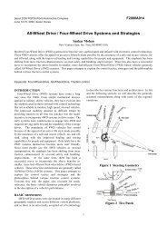
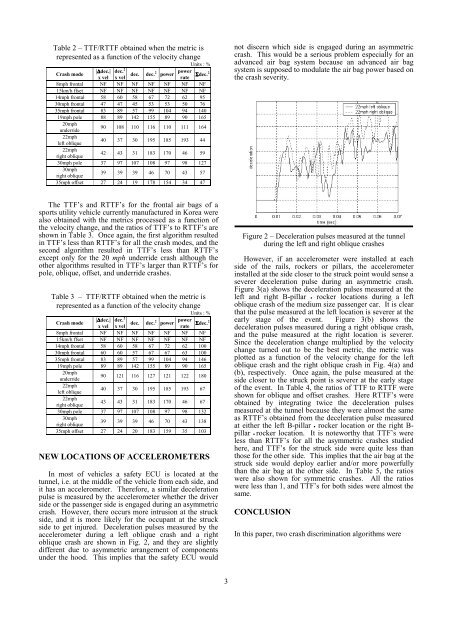
side to get injured. Deceleration pulses measured by the<br />
accelerometer during a left oblique crash <strong>and</strong> a right<br />
oblique crash are shown in Fig. 2, <strong>and</strong> they are slightly<br />
different due to asymmetric arrangement <strong>of</strong> components<br />
under the hood. This implies that the safety ECU would<br />
Figure 2 – Deceleration pulses measured at the tunnel<br />
during the left <strong>and</strong> right oblique crashes<br />
However, if an accelerometer were installed at each<br />
side <strong>of</strong> the rails, rockers or pillars, the accelerometer<br />
installed at the side closer to the struck point would sense a<br />
severer deceleration pulse during an asymmetric crash.<br />
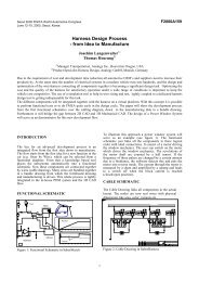
Figure 3(a) shows the deceleration pulses measured at the<br />
left <strong>and</strong> right B-pillar • rocker locations during a left<br />
oblique crash <strong>of</strong> the medium size passenger car. It is clear<br />
that the pulse measured at the left location is severer at the<br />
early stage <strong>of</strong> the event. Figure 3(b) shows the<br />
deceleration pulses measured during a right oblique crash,<br />
<strong>and</strong> the pulse measured at the right location is severer.<br />
Since the deceleration change multiplied by the velocity<br />
change turned out to be the best metric, the metric was<br />
plotted as a function <strong>of</strong> the velocity change for the left<br />
oblique crash <strong>and</strong> the right oblique crash in Fig. 4(a) <strong>and</strong><br />
(b), respectively. Once again, the pulse measured at the<br />
side closer to the struck point is severer at the early stage<br />
<strong>of</strong> the event. In Table 4, the ratios <strong>of</strong> TTF to RTTF were<br />
shown for oblique <strong>and</strong> <strong>of</strong>fset crashes. Here RTTF’s were<br />
obtained by integrating twice the deceleration pulses<br />
measured at the tunnel because they were almost the same<br />
as RTTF’s obtained from the deceleration pulse measured<br />
at either the left B-pillar • rocker location or the right B-<br />
pillar • rocker location. It is noteworthy that TTF’s were<br />
less than RTTF’s for all the asymmetric crashes studied<br />
here, <strong>and</strong> TTF’s for the struck side were quite less than<br />
those for the other side. This implies that the air bag at the<br />
struck side would deploy earlier <strong>and</strong>/or more powerfully<br />
than the air bag at the other side. In Table 5, the ratios<br />
were also shown for symmetric crashes. All the ratios<br />
were less than 1, <strong>and</strong> TTF’s for both sides were almost the<br />
same.<br />
CONCLUSION<br />
In this paper, two crash discrimination algorithms were<br />
3