X1-5 Assembly Instructions 22... - Life Fitness
X1-5 Assembly Instructions 22... - Life Fitness
X1-5 Assembly Instructions 22... - Life Fitness

Create successful ePaper yourself
Turn your PDF publications into a flip-book with our unique Google optimized e-Paper software.
Item Qty Description<br />
1<br />
2<br />
3<br />
4<br />
5<br />
6<br />
7<br />
8<br />
9<br />
10<br />
11<br />
12<br />
13<br />
14<br />
15<br />
16<br />
4<br />
14<br />
7<br />
2<br />
14<br />
2<br />
2<br />
2<br />
2<br />
2<br />
2<br />
8<br />
8<br />
1<br />
2<br />
6<br />
<strong>Assembly</strong> Guide:<br />
Look for the number coded<br />
hardware bags that match the<br />
assembly sequence.<br />
67 mm Hex Head Bolt<br />
Cap Washer<br />
Hex Head Nut<br />
30 mm Hex Head Bolt<br />
Plastic Cover Caps<br />
12 mm Phillips Screw<br />
Large Flat Washer<br />
Large Wave Washer<br />
Flat Washer<br />
Lock Washer<br />
20mm Hex Head Bolt<br />
16 mm Phillips Screw<br />
Lock Washer<br />
90 mm Hex Head Bolt<br />
81.5 mm Hex Head Bolt<br />
12 mm Phillips Screw<br />
1) 2)<br />
4)<br />
6) 5)<br />
3)<br />
11) 10) 9)<br />
7) 8)<br />
12)<br />
14)<br />
13) 3)<br />
15) 3)<br />
16)<br />
Hardware List<br />
10 20 30 40 50 60 70 80 90 100 110 120 130 140 150 160<br />
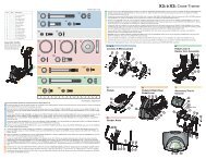
<strong>Assembly</strong> Sequence<br />
Tools required: Metric Socket set, Phillips Screwdriver, Metric Wrench set<br />
1. Position the base unit near the desired location for use (Refer to the "Getting Started" section of the User Manual for proper location). Locate and install the four<br />
LEVELER FEET (A) into the front and rear stabilizers as shown.<br />
2. With the DISPLAY CONSOLE MOUNTING PLATE (B) facing upward, lay the UPRIGHT TUBE ASSEMBLY (C) on floor in front of BASE FRAME (D). Cut the wire<br />
tie securing the LOWER WIRE HARNESS (E) to the front of the BASE FRAME. Connect the UPPER WIRE HARNESS (F) to the LOWER WIRE HARNESS.<br />
Position the UPRIGHT TUBE ASSEMBLY (C) between the plates on the front of the BASE FRAME (D). Feed any excess wire harness into the BASE FRAME. Tilt<br />
the UPRIGHT TUBE ASSEMBLY into an upright position. Align the holes on the plates with the holes on the UPRIGHT TUBE ASSEMBLY. Secure the UPRIGHT<br />
TUBE ASSEMBLY to the BASE FRAME using four 67 mm HEX HEAD BOLTS (1), eight CAP WASHERS (2) (4 on each side) and four NUTS (3). Leave BOLTS<br />
loose at this time.<br />
Using two 30 mm HEX HEAD BOLTS (4), secure the UPRIGHT TUBE ASSEMBLY (C) to the backside of the SUPPORT PLATE on the BASE FRAME (D). Tighten<br />
the BOLTS securely. Tighten the previous four HEX HEAD BOLTS (1) securely. Install eight black PLASTIC COVER CAPS (5) over each 67 mm HEX HEAD BOLT<br />
HEAD (1) and NUT (3).<br />
3. Slide the tab of the UPRIGHT TUBE ANGLE BRACE (G) into the slot located near the base of the UPRIGHT TUBE ASSEMBLY (C) and pivot the UPRIGHT TUBE<br />
ANGLE BRACE downward to met the BASE FRAME (D). Using two 12 mm SCREWS (6), secure the UPRIGHT TUBE ANGLE BRACE to the UPRIGHT TUBE<br />
ASSEMBLY and BASE FRAME as shown.<br />
4. Slide one LARGE FLAT WASHER (7) and one LARGE WAVE WASHER (8) onto the USER RIGHT PIVOT SHAFT (H). Slide the WASHERS fully over the PIVOT<br />
SHAFT until seated against the pre-installed stop ring.<br />
Locate the USER RIGHT ROCKER ARM ASSEMBLY (J) (Marked with an “R”). With the top handgrip facing the front of the unit (as shown), slide the USER RIGHT<br />
ROCKER ARM ASSEMBLY onto the USER RIGHT PIVOT SHAFT (H) until seated against the WASHERS (7 & 8). Secure the ROCKER ARM ASSEMBLY to the<br />
PIVOT SHAFT using one FLAT WASHER (9), LOCK WASHER (10), and 20 mm HEX HEAD BOLT (11). Tighten the BOLT securely. Insert one ROCKER ARM<br />
END CAP (K) into the end of the ROCKER ARM SHAFT. Repeat the procedure for the USER LEFT ROCKER ARM ASSEMBLY (L).<br />
5. Locate the USER RIGHT PEDAL LEVER (M) and PEDAL (N) (marked with an “R”). Position the PEDAL above the PEDAL MOUNTING PLATE (O) and secure the<br />
PEDAL using four 16 mm SCREWS (12) and LOCK WASHERS (13). Tighten the SCREWS securely. Repeat for the USER LEFT PEDAL (P) and PEDAL LEVER<br />
(Q).<br />
6. Position the rear end of the USER RIGHT PEDAL LEVER (M) near the USER RIGHT REAR CLEVIS (R). Position the end of the PEDAL LEVER between the<br />
clevis flanges. Align the holes and secure as shown using two CLEVIS COVERS (S), two CAP WASHERS (2), one 90 mm HEX HEAD BOLT (14), one NUT (3)<br />
and two PLASTIC COVER CAPS (5). Tighten the BOLT and NUT securely.<br />
4.<br />
Pedal Arms<br />
<strong>X1</strong>5 Cross-Trainer<br />
7. Lift the front end of the USER RIGHT PEDAL LEVER (M) to meet the USER RIGHT ROCKER ARM CLEVIS (T). Secure the PEDAL LEVER to the ROCKER ARM<br />
CLEVIS using two CAP WASHERS (2), one 81.5 mm HEX HEAD BOLT (15), one NUT (3) and two PLASTIC COVER CAPS (5). Tighten the BOLT and NUT<br />
securely. Repeat the procedure for the USER LEFT PEDAL LEVER (Q) and ROCKER ARM CLEVIS (U).<br />
8. Position the DISPLAY CONSOLE (V) over the DISPLAY CONSOLE MOUNTING PLATE (B) located at the top of the UPRIGHT TUBE ASSEMBLY (C). Plug the<br />
CONNECTOR (W) leading from the DISPLAY CONSOLE MOUNTING PLATE into the corresponding CONNECTOR in the back of the DISPLAY CONSOLE. Make<br />
sure the CONNECTOR snaps into place. Push excess wire harness into the opening of the DISPLAY CONSOLE MOUNTING PLATE.<br />
Secure the DISPLAY CONSOLE (V) to the DISPLAY CONSOLE MOUNTING PLATE (B) using four 12 mm SCREWS (16). Tighten the SCREWS securely.<br />
CAUTION: Be careful not to pinch the wire harness when assembling the DISPLAY CONSOLE (V) to the DISPLAY CONSOLE MOUNTING PLATE (B).<br />
9. Secure the WATER BOTTLE BRACKET (X) to the UPRIGHT TUBE ASSEMBLY (C) as shown using two 12 mm SCREWS (16). Tighten the SCREWS securely.<br />
Insert the WATER BOTTLE (Y) into the WATER BOTTLE BRACKET.<br />
10. Refer to the "Getting Started" section of the User Manual for proper location, stabilizing, and POWER ADAPTER instructions.<br />
5<br />
1.&2.&3. 5.&6.<br />
7.<br />
Levelers & Monocolumn Pedals & Right Rear<br />
Pedal Lever &<br />
Pedal Lever<br />
Rocker Arm <strong>Assembly</strong><br />
3<br />
4<br />
6<br />
G<br />
2<br />
E<br />
F<br />
H<br />
C<br />
D<br />
7<br />
2<br />
C<br />
A<br />
B<br />
1<br />
8 J<br />
5<br />
9<br />
10<br />
11<br />
K<br />
5<br />
3<br />
2<br />
S<br />
P<br />
R<br />
Q<br />
S<br />
2<br />
14<br />
O<br />
5<br />
N<br />
13<br />
12<br />
Y<br />
X<br />
M<br />
16<br />
U<br />
5<br />
3<br />
8.&9.<br />
Console & Water Bottle<br />
W<br />
2<br />
C<br />
T<br />
U<br />
16<br />
2<br />
B<br />
5<br />
15
© 2005 <strong>Life</strong> <strong>Fitness</strong>, a division of Brunswick Corporation. All rights reserved. <strong>Life</strong> <strong>Fitness</strong> is a registered trademarks of Brunswick<br />
Corporation. Any use of this trademark, without the express written consent of <strong>Life</strong> <strong>Fitness</strong> is forbidden. 7823801 (05/05)<br />
5100 N. RIVER ROAD, SCHILLER PARK, ILLINOIS 60176<br />
LIFEFITNESS.COM<br />
<strong>Life</strong> <strong>Fitness</strong> offers a full line of premier fitness equipment for the home.<br />
TOTAL-BODY ELLIPTICAL CROSS-TRAINERS | TREADMILLS | LIFECYCLE EXERCISE BIKES<br />
STAIRCLIMBERS | GYM SYSTEMS<br />
®<br />
<strong>X1</strong>5 Cross-Trainer<br />
ASSEMBLY<br />
INSTRUCTIONS