Inventor's Guide - VEX Robotics
Inventor's Guide - VEX Robotics
Inventor's Guide - VEX Robotics

You also want an ePaper? Increase the reach of your titles
YUMPU automatically turns print PDFs into web optimized ePapers that Google loves.
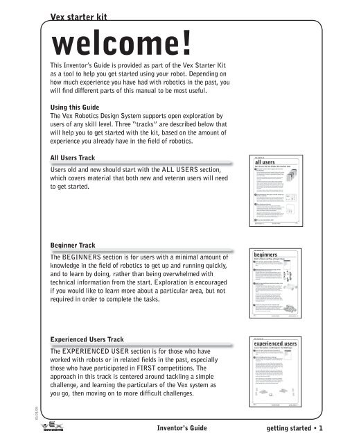
Vex starter kit<br />
welcome!<br />
This Inventor’s <strong>Guide</strong> is provided as part of the Vex Starter Kit<br />
as a tool to help you get started using your robot. Depending on<br />
how much experience you have had with robotics in the past, you<br />
will find different parts of this manual to be most useful.<br />
Using this <strong>Guide</strong><br />
The Vex <strong>Robotics</strong> Design System supports open exploration by<br />
users of any skill level. Three “tracks” are described below that<br />
will help you to get started with the kit, based on the amount of<br />
experience you already have in the field of robotics.<br />
All Users Track<br />
Users old and new should start with the ALL USERS section,<br />
which covers material that both new and veteran users will need<br />
to get started.<br />
Beginner Track<br />
The BEGINNERS section is for users with a minimal amount of<br />
knowledge in the field of robotics to get up and running quickly,<br />
and to learn by doing, rather than being overwhelmed with<br />
technical information from the start. Exploration is encouraged<br />
if you would like to learn more about a particular area, but not<br />
required in order to complete the tasks.<br />
Experienced Users Track<br />
The EXPERIENCED USER section is for those who have<br />
worked with robots or in related fields in the past, especially<br />
those who have participated in FIRST competitions. The<br />
approach in this track is centered around tackling a simple<br />
challenge, and learning the particulars of the Vex system as<br />
you go, then moving on to more difficult challenges.<br />
01/31/05<br />
Inventor’s <strong>Guide</strong><br />
getting started • 1
Vex starter kit<br />
all users<br />
How to use the Vex Starter Kit the first time<br />
1 Unwrap the Inventor’s <strong>Guide</strong> chapters and insert them<br />
into the binder.<br />
Start with the packet containing the Subsystem Dividers (with the colored<br />
tabs), then add the chapter packets in behind the appropriate dividers. If<br />
your subsystems get out of order, the supplied table of contents can help<br />
you set them straight.<br />
Your Inventor’s <strong>Guide</strong> Binder is the central repository for information<br />
about the Vex <strong>Robotics</strong> Design System and all its components and<br />
accessories.<br />
The Starter Kit includes the first set of chapters, but as your designs<br />
evolve, you will add new parts and accessories that will expand your<br />
robotic repertoire. Whenever you decide to expand your robot’s horizons,<br />
your binder will expand with them. Every accessory and part in the Vex<br />
line comes with all the information you need on a page that drops right<br />
into your binder so you don’t need to worry about losing it—or getting<br />
lost yourself.<br />
Your kit also includes a product registration card packed on top of the<br />
documentation, which you should fill out and send in before you forget.<br />
2 Take an inventory of all the parts in the kit to make sure<br />
you have everything.<br />
Turn to Appendix D at the back of your newly constructed binder, and use<br />
the parts listing there to make sure you have all the pieces in the kit. If<br />
you have parts storage bins or an organizer case, this would be a great<br />
time to unpack the parts from the box and move them to their new homes.<br />
3 Start charging your batteries<br />
Standard AA alkaline batteries can be used to power the Radio<br />
Transmitter for your first few uses if needed, but the Vex Micro Controller<br />
cannot be run on alkaline AAs. You will need a set of non-alkaline<br />
(preferably NiCd) rechargeable batteries. See the Power Subsystem<br />
section of the Inventor’s <strong>Guide</strong> for more information.<br />
Since batteries typically take between 4 and 14 hours to charge<br />
(depending on your charger) and are typically shipped empty or with only<br />
a partial charge, you should plug them in now so they will be ready as<br />
soon as possible. In order to ensure a healthy battery charging cycle,<br />
don’t use the batteries until they have finished charging.<br />
4 You are now ready to build a robot!<br />
01/31/05<br />
getting started • 2<br />
Inventor’s <strong>Guide</strong>
Vex starter kit<br />
beginners<br />
Build a Robot and Play a Simple Game<br />
1 Review the basic safety instructions in Appendix A<br />
Always work safely. Although the Vex robot and parts are not dangerous<br />
under most circumstances, there are still safety precautions that you must<br />
follow.<br />
2 Begin by breaking your team into six groups, one for<br />
each subsystem in the Vex system<br />
If you don’t have a team, or there are not enough people to make six<br />
groups, feel free to give multiple responsibilities to the same group or<br />
person. It is often advantageous for individual team members to have<br />
specialized knowledge of the different subsystems when working on the<br />
robot together, but it is not unreasonable for one person to be able to<br />
perform several or even all of the functions needed to work on the robot<br />
at this point.<br />
3 Build the Squarebot Chassis using the instructions in the<br />
Inventor’s <strong>Guide</strong><br />
At the beginning of the Structure Subsystem chapter, you will find a list<br />
of materials, a short introduction to the subsystem, and then building<br />
instructions for the chassis of the Squarebot. The Structure and Motion<br />
teams should pay special attention to this portion of the robot, but<br />
everybody can help build it by collecting the parts and tools as they are<br />
needed.<br />
If desired, the non-chassis (Power, Sensor, Logic, and Control) teams<br />
can work ahead and try to hook together their subsystems without<br />
the chassis, and use the third Motor Module in the kit (which is not<br />
needed for the Squarebot design) to test their setup. Teams may want<br />
to remove and separate their respective sections of the Inventor’s <strong>Guide</strong><br />
temporarily while doing this, but any sections removed should be replaced<br />
immediately afterward!<br />
4 Combine the subsystems into the completed robot<br />
Once you complete the chassis, the remaining subsystems (Power, Sensor,<br />
Logic, and Control) can now turn to their respective chapters and use<br />
those building instructions to attach their components to the basic<br />
Squarebot chassis. This includes both physically attaching the subsystems<br />
to the chassis and connecting the cables.<br />
01/31/05<br />
Inventor’s <strong>Guide</strong><br />
getting started • 3
Vex starter kit<br />
beginners, continued<br />
5 Test the robot<br />
Once you have completed the robot, extend the antenna on the Radio<br />
Control Transmitter and turn it on by flipping the power switch on the<br />
front of the transmitter.<br />
Once the Transmitter is on, you can turn on the Vex Micro Controller<br />
module on the robot by flipping its power switch (located next to the<br />
battery port).<br />
You should see green lights for the Power Status and Rx1, and the<br />
large light blinking occasionally.<br />
If you built and connected everything according to the instructions,<br />
you should now be able to drive the robot around using the sticks on<br />
your Radio Control Transmitter. The controls are as follows:<br />
Left stick<br />
Right stick<br />
Forward<br />
Reverse<br />
Turn Left<br />
Turn Right<br />
In addition, the bumper switch sensors on the front and rear of your<br />
robot are configured to act as “tag points.” When they are hit by<br />
another robot or obstacle, your robot will be temporarily disabled.<br />
01/31/05<br />
getting started • 4<br />
Inventor’s <strong>Guide</strong>
Vex starter kit<br />
beginners, continued<br />
6 Solo Soccer Challenge<br />
Your first challenge awaits you in Appendix C, the Challenges section<br />
of the Inventor’s <strong>Guide</strong>. Turn to Appendix C, and read the challenge<br />
titled “Solo Soccer”.<br />
First, find a usable area of floor space. Tables are not recommended<br />
for challenges because they are too small, and they pose a danger for<br />
robots which may accidentally run off the edges. A carpeted playing<br />
surface will make the game easier (the ball will not roll away as<br />
easily), while a hard, smooth surface will make for quite a challenge,<br />
indeed!<br />
Place the two goal uprights (empty soft drink cans or toilet paper<br />
tubes work well for this) about a foot apart, and place the ball on<br />
the ground three or four feet away. Drive the robot so that it pushes<br />
the ball through the goal, without driving the robot through as well.<br />
Don’t hit the bumper on the front of the robot, or you will lose control<br />
for a few seconds… it’s soccer, you’re going to have to dribble!<br />
The first few times you try this challenge, you may want to simplify<br />
the task a little by starting the ball and robot in line with the goal.<br />
You can work your way up to the actual challenge. Once you have<br />
succeeded a few times, try the challenge as written by starting the<br />
ball and robot in different positions that are not lined up with the<br />
goal mouth.<br />
01/31/05<br />
Inventor’s <strong>Guide</strong><br />
getting started • 5
Vex starter kit<br />
beginners, continued<br />
7 Improve your Design<br />
Just like with stock car racing, the generic all-purpose design of the<br />
Squarebot is a good starting point, but you can do much, much<br />
better! Think about how you might want to customize or “soup-up”<br />
your design to solve a problem. For example: Did you notice how<br />
difficult it was to get the ball to turn with the robot once it was<br />
moving? Can you think of any ways you might be able to fix that<br />
problem? Implement your solution and play the game again!<br />
8 Challenges<br />
When you’re ready to move on to new, more challenging scenarios,<br />
turn to the challenges in Appendix C. Pick one of the other challenges<br />
there, and go for it! Formulate a strategy to accomplish the goals<br />
in the game, and implement your robotic solutions. As you plan<br />
and build your robot, consult the Inventor’s <strong>Guide</strong> for background<br />
information about the components you have available, and refer to<br />
the Squarebot subsystems you built for ideas. Good luck!<br />
9 Venture Forth<br />
The Vex <strong>Robotics</strong> website provides a wealth of support and challenge<br />
ideas beyond the starter set supplied in this kit.<br />
If you need a hand with your robot, or you want to learn about new<br />
accessories and challenges, visit http://www.vexrobotics.com.<br />
Inventor’s <strong>Guide</strong> Resources visited in this track:<br />
• Safety in Appendix A<br />
• Glossary in Appendix B<br />
• Challenges from Appendix C<br />
• Squarebot Parts & Assembly in each subsystem chapter<br />
• The System Map poster included in the Starter Kit<br />
• The Registration Card included in the Starter Kit<br />
01/31/05<br />
getting started • 6<br />
Inventor’s <strong>Guide</strong>
Vex starter kit<br />
experienced users<br />
Learn the System and Complete the Challenges<br />
1 Review the basic safety instructions in Appendix A<br />
Always work safely. Although the Vex robot and parts are not dangerous<br />
under most circumstances, there are still safety precautions that you must<br />
follow.<br />
2 The First Challenge: Solo Soccer Challenge<br />
Your first challenge awaits you in Appendix C, the Challenges section of<br />
the Inventor’s <strong>Guide</strong>. Turn to Appendix C, and read the challenge titled<br />
“Solo Soccer”.<br />
First, find a usable area of floor space. Tables are not recommended for<br />
challenges because they are too small, and they pose a danger for robots<br />
which may accidentally run off the edges. A carpeted playing surface will<br />
make the game easier (the ball will not roll away as easily), while a hard,<br />
smooth surface will make for quite a challenge, indeed!<br />
Place the two goal uprights (empty soft drink cans or toilet paper tubes<br />
work well for this) about a foot apart, and place the ball on the ground<br />
three or four feet away. Drive the robot so that it pushes the ball through<br />
the goal, without driving the robot through as well. Don’t hit the bumper<br />
on the front of the robot, or you will lose control for a few seconds… it’s<br />
soccer, you’re going to have to dribble!<br />
The first few times you try this challenge, you may want to simplify the<br />
task a little by starting the ball and robot in line with the goal. You can<br />
work your way up to the actual challenge. Once you have succeeded a few<br />
times, try the challenge as written by starting the ball and robot in<br />
different positions that are not lined up with the goal mouth.<br />
01/31/05<br />
Inventor’s <strong>Guide</strong><br />
getting started • 7
Vex starter kit<br />
experienced users, continued<br />
3 Design and Build a Robot to Play the Game<br />
Your team must come up with a strategy and build a robot to play<br />
Solo Soccer. You may use any methods you like to organize your<br />
team efforts to plan and complete the robot, but a suggested method<br />
would be to break the team up into groups and assign responsibility<br />
for a few of the major robot subsystems to each group.<br />
If you need ideas or assistance in the construction of any of the<br />
subsystems (Structure, Motion, Power, Sensors, Logic, or Control),<br />
flip to the appropriate section in the Inventor’s <strong>Guide</strong>. You will find<br />
a variety of information there, from background information about<br />
the workings of the components, to building instructions for a sample<br />
implementation of each subsystem on a robot called<br />
Squarebot. The examples are probably the most useful, as they<br />
illustrate both the construction and connecting that you will need<br />
in order to get your subsystems working together. The System Map<br />
(the large stand-alone poster sheet included with the Starter Kit)<br />
identifies the accessories that will allow you to easily expand your<br />
Vex <strong>Robotics</strong> Design System.<br />
If you prefer to start with a basic robot and modify from there, then<br />
all you need to do is build all the subsystem examples. The six sample<br />
subsystems that are provided are all pieces of the Squarebot, and<br />
when attached according to the instructions in the chapters, you will<br />
have a simple, but working, robot that you can use as a starting point<br />
for your own designs.<br />
Regarding ports and joystick controls, Appendix E has a full listing<br />
of control layouts that are available to you. The default controls are<br />
the simplest to deal with initially (because every channel controls the<br />
same-numbered motor port), but you may want to try switching to<br />
arcade-style controls to see if you like them better.<br />
01/31/05<br />
getting started • 8<br />
Inventor’s <strong>Guide</strong>
Vex starter kit<br />
experienced users, continued<br />
4 Test the robot<br />
Once you have completed the robot (or even just a portion of it that<br />
you want to test), extend the antenna on the Transmitter and turn it<br />
on by flipping the power switch on the front.<br />
Once the Transmitter is on, you can turn on the Vex Micro Controller<br />
module on the robot by flipping its power switch (located next to the<br />
battery port).<br />
You should see green lights for the Power Status and Rx1, and the<br />
large light blinking occasionally.<br />
You now have control over your robot. Remember that each axis of<br />
the stick or pair of buttons controls one of the output ports, so see<br />
if you can get your robot to move. You may want to try lifting it up<br />
if it looks stuck. Some motors may be trying to turn, but may be<br />
encountering unexpected resistance from other parts. Again, consult<br />
the Squarebot sample subsystems if you need help.<br />
01/31/05<br />
Inventor’s <strong>Guide</strong><br />
getting started • 9
Vex starter kit<br />
experienced users, continued<br />
5 Soccer Time<br />
Play the game! Challenge other teams for the best time, or see how<br />
many times in a row you can succeed by yourself.<br />
6 Improve your Design<br />
Nobody gets everything perfect the first time. Maybe your robot had<br />
trouble handling the ball in a turn, or maybe you think an entirely<br />
different strategy would work better. Go back and try it!<br />
7 Challenges<br />
When you’re ready to move on to new, more challenging scenarios,<br />
turn to the Challenges chapter in the back of the Inventor’s <strong>Guide</strong>.<br />
Pick one of the challenges there, and organize a tournament.<br />
Formulate a strategy to accomplish the goals in the game, and<br />
implement your robotic solutions. As you plan and build your robot,<br />
consult the Inventor’s <strong>Guide</strong> for background information about the<br />
components you have available, and refer to the example subsystems<br />
for ideas.<br />
8 Venture Forth<br />
The Vex <strong>Robotics</strong> website provides a wealth of support and challenge<br />
ideas beyond the starter set supplied in this kit.<br />
Visit http://www.vexrobotics.com and get ready to join the worldwide<br />
community of Vex inventors. Good luck!<br />
Inventor’s <strong>Guide</strong> Resources visited in this track:<br />
• Safety in Appendix A<br />
• Glossary in Appendix B<br />
• Challenges from Appendix C<br />
• Squarebot Parts & Assembly in each subsystem chapter<br />
• The System Map poster included in the Starter Kit<br />
• The Registration Card included in the Starter Kit<br />
01/31/05<br />
getting started • 10<br />
Inventor’s <strong>Guide</strong>
Vex starter kit<br />
Vex<br />
Inventor’s<br />
<strong>Guide</strong><br />
table of contents:<br />
Structure Subsystem 2.1<br />
Motion Subsystem 3.1<br />
Power Subsystem 4.1<br />
Sensor Subsystem 5.1<br />
Control Subsystem 6.1<br />
Logic Subsystem 7.1<br />
Programming Subsystem 8.1<br />
Reference<br />
Inventor’s <strong>Guide</strong><br />
table of contents • 1
Vex starter kit<br />
The FCC Wants You to Know<br />
This equipment has been tested and found to comply with the limits for<br />
radio controlled devices, pursuant to Part 15 and Part 95 of the FCC Rules.<br />
These limits are designed to provide reasonable protection against harmful<br />
interference. This equipment generates, uses, and can radiate radio frequency<br />
energy and, if not installed and used in accordance with the instructions, may<br />
cause harmful interference to radio communications. However, there is no<br />
guarantee that interference will not occur in a particular installation. If this<br />
equipment does cause harmful interference to radio or television reception, which<br />
can be determined by turning the equipment off and on, the user is encouraged to<br />
try to correct the interference by one or more of the following measures:<br />
• Reorient or relocate the receiving antenna.<br />
• Increase the separation between the equipment and receiver.<br />
• Consult your local electronics store or an experienced radio/TV<br />
technician for help.<br />
• If you cannot eliminate the interference, the FCC requires that you stop using<br />
your R/C transmitter.<br />
Warning: Changes or modifications note expressly approved by Innovation One<br />
may cause interference and void the user’s authority to operate the equipment.<br />
Only use authorized crystals designed for use with the Vex <strong>Robotics</strong> Design<br />
System RF Receiver.<br />
Important: The EPA certified RBRC® Battery<br />
Recycling Seal on the nickel-cadmium (Ni-Cd)<br />
battery indicates Innovation One voluntarily<br />
participates in an industry program that collects and<br />
recycles NiCd batteries at the end of their useful<br />
life, when taken out of service in the United States<br />
or Canada. The RBRC program provides a convenient<br />
alternative to placing used Ni-Cd batteries into the<br />
trash or the municipal waste stream, which may be<br />
illegal in your area. Please call 1-800-8-battery for<br />
information on Ni-Cd battery recycling and disposal<br />
bans/restrictions in your area. Innovation One’s<br />
involvement in this program is part of the company’s<br />
commitment to preserving our environment and<br />
conserving our natural resources.<br />
Limited 90-day Warranty<br />
This product is warranted by Innovation One against manufacturing defects<br />
in material and workmanship under normal use for ninety (90)<br />
days from the date of purchase from authorized Innovation One dealers. For<br />
complete warranty details and exclusions, check with your dealer.<br />
Innovation One, Inc.<br />
350 North Henderson Street<br />
Fort Worth, TX 76102<br />
11/04<br />
Printed in China<br />
© 2005 Innovation One. All Rights Reserved.<br />
Vex and Vex <strong>Robotics</strong> Design System are trademarks of Innovation One.<br />
The actual product may vary from images depicted in this Inventor’s <strong>Guide</strong>.<br />
table of contents • 2<br />
Inventor’s <strong>Guide</strong>
The structural<br />
subsystem<br />
of the robot is<br />
responsible for<br />
physical support.<br />
It holds everything<br />
in place, and is,<br />
in effect, the<br />
durable “skeleton”<br />
of the robot to<br />
which all the other<br />
subsystems are<br />
attached.<br />
structure
structure<br />
structure<br />
table of contents:<br />
squarebot chassis parts and assembly 2.2<br />
concepts to understand 2.27<br />
subsystems interfaces 2.37<br />
structure subsystem inventory 2.38<br />
01/31/05<br />
Inventor’s <strong>Guide</strong><br />
2 • 1
structure<br />
squarebot chassis parts and assembly<br />
The Structure and Motion subsystems are<br />
very tightly integrated to form the chassis<br />
of the Squarebot.<br />
The chassis assembly instructions refer to<br />
components from both the Structure and<br />
Motion sections.<br />
Follow the steps in this section to build the<br />
chassis.<br />
squarebot assembly<br />
1 Collect and identify the parts<br />
from the list of materials below:<br />
materials<br />
qty<br />
structure subsystem<br />
bearing flat 12<br />
panel 1<br />
chassis rail 4<br />
chassis bumper 2<br />
partially threaded beams, 2" 4<br />
keps nut 38<br />
8-32 hex screw, ¼" 26<br />
8-32 hex screw, ½" 20<br />
motor 2<br />
2.75" removable tire 4<br />
1.895" detachable hub 4<br />
36-tooth gear 4<br />
60-tooth gear 2<br />
collar w/ threaded set screw 10<br />
square bar, 2" 2<br />
square bar, 3" 4<br />
6-32 hex screw, ½" 4<br />
01/31/05<br />
motion subsystem<br />
2 • 2<br />
Inventor’s <strong>Guide</strong>
structure<br />
squarebot assembly<br />
squarebot chassis parts and assembly, continued<br />
chassis rail x 4<br />
chassis bumper x 2<br />
2" partially threaded beam x 4<br />
8-32 hex screw, ¼" x 26<br />
keps nut x 38<br />
8-32 hex screw, ½" x 20<br />
6-32 hex screw, ½" x 4<br />
01/31/05<br />
Inventor’s <strong>Guide</strong><br />
2 • 3
structure<br />
squarebot assembly<br />
squarebot chassis parts and assembly, continued<br />
panel x 1 motor x 2<br />
2.75" removable tire x 4<br />
1.895" detachable hub x 4<br />
01/31/05<br />
2 • 4<br />
Inventor’s <strong>Guide</strong>
structure<br />
squarebot assembly<br />
squarebot chassis parts and assembly, continued<br />
36 tooth gear x 4<br />
collar w/threaded set screw x 10<br />
square bar, 2" x 2<br />
.5"<br />
square bar, 3" x 4<br />
60 tooth gear x 2<br />
bearing flat x 12<br />
01/31/05<br />
Inventor’s <strong>Guide</strong><br />
2 • 5
structure<br />
squarebot assembly<br />
squarebot chassis parts and assembly, continued<br />
2 Inner chassis rails<br />
You will need two chassis rails, one for the right side and one for the left<br />
side. Orient them as shown, so that the narrow face is pointing up and the<br />
“open” sides are facing each other.<br />
Parts needed in this step:<br />
x 2<br />
Add four bearing flats to the chassis rails (two per rail, on the<br />
outward-facing sides). Be sure to position the bearing flats such that<br />
the central hole of each bearing flat is aligned with the fourth hole<br />
from the respective end of the chassis rail, as shown.<br />
Parts needed in this step:<br />
x 4<br />
01/31/05<br />
2 • 6<br />
Inventor’s <strong>Guide</strong>
structure<br />
squarebot assembly<br />
squarebot chassis parts and assembly, continued<br />
2 Inner chassis rails, continued<br />
Secure the bearing flats to the chassis rails using two ½" 8-32 screws<br />
and two keps nuts per bearing flat, as shown.<br />
Parts needed in this step:<br />
½"<br />
x 8<br />
x 8<br />
Your completed inner chassis rails should look like this when you’re done:<br />
01/31/05<br />
Inventor’s <strong>Guide</strong><br />
2 • 7
structure<br />
squarebot assembly<br />
squarebot chassis parts and assembly, continued<br />
2 Outer chassis rails<br />
Position two more chassis rails as shown, just as you did for the inner<br />
chassis rails.<br />
Parts needed in this step:<br />
x 2<br />
Connect two 2" partially threaded beams to each of the rails, using a<br />
¼" 8-32 screw for each beam. Position the rear beam on the fourth square hole<br />
from the back end of the chassis rail, and the front beam on the fifth square<br />
hole from the front end of the chassis rail.<br />
Parts needed in this step:<br />
2" ¼"<br />
x 4<br />
x4<br />
01/31/05<br />
2 • 8<br />
Inventor’s <strong>Guide</strong>
structure<br />
squarebot assembly<br />
squarebot chassis parts and assembly, continued<br />
2 Outer chassis rails, continued<br />
Add bearing flats to the inner faces of the two chassis rails.<br />
The center hole of the bearing flat should be aligned with the eighth<br />
hole from the front end of the chassis rail, in the middle row of holes.<br />
Parts needed in this step:<br />
x 2<br />
Secure each bearing flat with two ½" 8-32 screws and two keps nuts.<br />
Parts needed in this step:<br />
½"<br />
x 4 x 4<br />
01/31/05<br />
Inventor’s <strong>Guide</strong><br />
2 • 9
structure<br />
squarebot assembly<br />
squarebot chassis parts and assembly, continued<br />
2 Outer chassis rails, continued<br />
Your outer chassis rails should now look like this:<br />
Now add two bearing flats to the outer surface of each chassis<br />
rail, so the center hole of each bearing flat is over the fourth<br />
hole from the respective end of the chassis rail, as shown. These<br />
are the same positions as the bearing flats you put on the inner<br />
chassis rails earlier.<br />
Parts needed in this step:<br />
x 4<br />
01/31/05<br />
2 • 10<br />
Inventor’s <strong>Guide</strong>
structure<br />
squarebot assembly<br />
squarebot chassis parts and assembly, continued<br />
2 Outer chassis rails, continued<br />
Again, secure the bearing flats to the chassis rails using two<br />
two ½" 8-32 screws and two keps nuts per bearing flat.<br />
Parts needed in this step:<br />
½"<br />
x 8 x 8<br />
Your outer chassis rails should now look like this:<br />
01/31/05<br />
Inventor’s <strong>Guide</strong><br />
2 • 11
structure<br />
squarebot assembly<br />
squarebot chassis parts and assembly, continued<br />
3 Motor Subassembly<br />
Before starting on the motor subassembly, make sure that the clutch<br />
is installed in the motor, as shown.<br />
Parts needed in this step:<br />
x 2<br />
Insert a 2" square beam into each clutch, making sure that they seat<br />
firmly. The square bar will act as the motor’s drive shaft.<br />
Parts needed in this step:<br />
2"<br />
x 2<br />
01/31/05<br />
2 • 12<br />
Inventor’s <strong>Guide</strong>
structure<br />
squarebot assembly<br />
squarebot chassis parts and assembly, continued<br />
3 Motor Subassembly, continued<br />
Slide the pre-assembled inner chassis rails onto the square bar motor<br />
shafts, so that the shafts go through the middle hole in the middle<br />
row of each rail.<br />
Install one bearing flat on the outward-facing side of each<br />
chassis rail, with the front hole of the bearing flat sliding onto<br />
the motor shaft as shown.<br />
Parts needed in this step:<br />
x 2<br />
01/31/05<br />
Inventor’s <strong>Guide</strong><br />
2 • 13
structure<br />
squarebot assembly<br />
squarebot chassis parts and assembly, continued<br />
3 Motor Subassembly, continued<br />
Your assembly should now look like this:<br />
Secure the bearing flat to the inner chassis rail and motor using two<br />
½" 6-32 screws per motor. Note that these are the thinner screws,<br />
not the usual 8-32 ones.<br />
Parts needed in this step:<br />
½"<br />
x 4<br />
Your assembly should now look like this:<br />
01/31/05<br />
2 • 14<br />
Inventor’s <strong>Guide</strong>
structure<br />
squarebot assembly<br />
squarebot chassis parts and assembly, continued<br />
3 Chassis Subassembly<br />
Insert a 3" square bar through the center hole of each unoccupied<br />
bearing flat, as shown. Don’t push them all the way through. Push<br />
the end of the bar about ¹/8" through the rail.<br />
Parts needed in this step:<br />
3” 3"<br />
x 4<br />
01/31/05<br />
Inventor’s <strong>Guide</strong><br />
2 • 15
structure<br />
squarebot assembly<br />
squarebot chassis parts and assembly, continued<br />
4 Chassis Subassembly, continued<br />
Slide metal collars (with threaded screws) onto each of the 2" and<br />
3" square bars, mounting them flush with the surface of the bearing<br />
flat against which they will sit. Be sure the square bars don’t get<br />
pushed too far in while you put the collars on, or you will not have<br />
enough bar sticking out to mount the wheels later.<br />
Parts needed in this step:<br />
x 6<br />
Once the collars and bars are in position, tighten the threaded screws<br />
with the smaller 5/64" hex L wrench to keep the collars from<br />
sliding out of place.<br />
01/31/05<br />
2 • 16<br />
Inventor’s <strong>Guide</strong>
structure<br />
squarebot assembly<br />
squarebot chassis parts and assembly, continued<br />
4 Chassis Subassembly, continued<br />
Slide a 60-tooth gear onto the drive axle of each motor, pushing it<br />
flush against the collar that you added in the previous step.<br />
Parts needed in this step:<br />
60-tooth<br />
x 2<br />
01/31/05<br />
Inventor’s <strong>Guide</strong><br />
2 • 17
structure<br />
squarebot assembly<br />
squarebot chassis parts and assembly, continued<br />
4 Chassis Subassembly, continued<br />
Slide a 36-tooth gear onto each of the remaining square bars,<br />
pushing them flush against the collars.<br />
Parts needed in this step:<br />
36-tooth<br />
x 4<br />
01/31/05<br />
2 • 18<br />
Inventor’s <strong>Guide</strong>
structure<br />
squarebot assembly<br />
squarebot chassis parts and assembly, continued<br />
4 Chassis Subassembly, continued<br />
Add another collar to the end of each 3" square bar, again pushing<br />
them flush against the face of the gear before tightening the screws.<br />
Parts needed in this step:<br />
x 4<br />
Tighten the threaded screws with a 35/64" hex L wrench.<br />
01/31/05<br />
Inventor’s <strong>Guide</strong><br />
2 • 19
structure<br />
squarebot assembly<br />
squarebot chassis parts and assembly, continued<br />
4 Chassis Subassembly, continued<br />
Install the pre-assembled outer chassis rails onto the current<br />
assembly. All three of the square bars sticking out of the inner rail<br />
should go neatly through bearing flats on the outer rail.<br />
Note: If you find that your gears are sliding on the axles, you<br />
can insert the 0.182" and 0.318" plastic spacers included in the kit<br />
to block them into place.<br />
01/31/05<br />
2 • 20<br />
Inventor’s <strong>Guide</strong>
structure<br />
squarebot assembly<br />
squarebot chassis parts and assembly, continued<br />
4 Chassis Subassembly, continued<br />
Place chassis bumpers on the front and rear of the chassis rails,<br />
as shown.<br />
Parts needed in this step:<br />
x 2<br />
01/31/05<br />
Inventor’s <strong>Guide</strong><br />
2 • 21
structure<br />
squarebot assembly<br />
squarebot chassis parts and assembly, continued<br />
4 Chassis Subassembly, continued<br />
Secure the vertical faces of the chassis bumpers to the end of the<br />
chassis rails using four ¼" 8-32 screws and keps nuts in the front,<br />
and four in the back.<br />
Parts needed in this step:<br />
¼"<br />
x 8 x 8<br />
01/31/05<br />
2 • 22<br />
Inventor’s <strong>Guide</strong>
structure<br />
squarebot assembly<br />
squarebot chassis parts and assembly, continued<br />
4 Chassis Subassembly, continued<br />
Secure the horizontal faces of the chassis bumpers to the top of the<br />
chassis rails using ¼" 8-32 screws and keps nuts, six in the front and<br />
four in the back.<br />
These holes remain open to allow<br />
other subsystems to use them as<br />
attachment points.<br />
Parts needed in this step:<br />
¼"<br />
x 10 x 10<br />
01/31/05<br />
Inventor’s <strong>Guide</strong><br />
2 • 23
structure<br />
squarebot assembly<br />
squarebot chassis parts and assembly, continued<br />
4 Deck Subassembly<br />
Place the large flat panel on the 2" partially threaded beams,<br />
aligning each corner of the panel with one of the threaded beams.<br />
Parts needed in this step:<br />
x 1<br />
01/31/05<br />
2 • 24<br />
Inventor’s <strong>Guide</strong>
structure<br />
squarebot assembly<br />
squarebot chassis parts and assembly, continued<br />
4 Deck Subassembly<br />
Secure the panel to the threaded beams with four ¼" 8-32 screws,<br />
as shown.<br />
Parts needed in this step:<br />
¼"<br />
x 4<br />
01/31/05<br />
Inventor’s <strong>Guide</strong><br />
2 • 25
structure<br />
squarebot assembly<br />
squarebot chassis parts and assembly, continued<br />
4 Deck Subassembly<br />
Install the small green tires (2.75" Removable Tire and 1.895" Hub)<br />
on the 3" square beams, as shown.<br />
Parts needed in this step:<br />
x 2<br />
Your Squarebot chassis is complete!<br />
01/31/05<br />
2 • 26<br />
Inventor’s <strong>Guide</strong>
structure<br />
concepts to understand<br />
Stability: Center of Gravity Considerations<br />
Center of Gravity<br />
You can think of the robot’s<br />
center of gravity as the “average<br />
position” of all the weight<br />
on the robot. Because it is an<br />
average of both weight and<br />
position, heavier objects count<br />
more than lighter ones in<br />
determining where the center<br />
of gravity is, and pieces that<br />
are farther out count more<br />
than pieces that are near the<br />
middle.<br />
Support Polygon<br />
The support polygon is the<br />
imaginary polygon formed by<br />
connecting the points where<br />
your robot touches the ground<br />
(usually the wheels). It varies<br />
by design, but there is always<br />
one support polygon in any<br />
stable configuration.<br />
Stability<br />
The rule for making a robot<br />
stable is very simple: the<br />
robot will be most stable<br />
when the center of gravity is<br />
centered over the polygon.<br />
Your robot will encounter<br />
much more complex situations<br />
than just standing still,<br />
however, and you need to take<br />
these into account when<br />
making your design.<br />
01/31/05<br />
Inventor’s <strong>Guide</strong><br />
2 • 27
structure<br />
concepts to understand, continued<br />
Stability: Center of Gravity Considerations, continued<br />
EXAMPLE 1: Towerbot<br />
This robot was built very tall<br />
so that it would be able to<br />
reach a hanging goal for a<br />
challenge. However, along the<br />
way, it had to first climb<br />
a ramp.<br />
Notice that the robot’s center<br />
of gravity is no longer over<br />
the support polygon. This<br />
robot would fall over as soon<br />
as it started up the ramp.<br />
01/31/05<br />
2 • 28<br />
Inventor’s <strong>Guide</strong>
structure<br />
concepts to understand, continued<br />
Stability: Center of Gravity Considerations, continued<br />
EXAMPLE 1: Towerbot,<br />
continued<br />
To fix this problem, you must<br />
lower the robot’s center of<br />
gravity so that it does not<br />
move as far when the robot<br />
is on an incline. In general,<br />
it is always advantageous to<br />
have your robot’s center of<br />
gravity as close to the ground<br />
as possible!<br />
Center of Gravity<br />
is Still Over<br />
Support Polygon<br />
01/31/05<br />
Inventor’s <strong>Guide</strong><br />
2 • 29
structure<br />
concepts to understand, continued<br />
Stability: Center of Gravity Considerations, continued<br />
EXAMPLE 2: Grabberbot<br />
This robot is designed to pick<br />
up a heavy object using the<br />
gripper claw on the front,<br />
and transport the object to<br />
another location.<br />
When the robot picks up the<br />
object, it effectively adds it<br />
to the robot’s structure. The<br />
combined robot-ball structure<br />
now has the new center of<br />
gravity (shown below), which<br />
is outside the support<br />
polygon. The robot tips over<br />
as a consequence.<br />
Center of Gravity<br />
is Directly Over<br />
Support Polygon<br />
(but not by much)<br />
Heavy Weight Near<br />
Front of Robot Moves<br />
Center of Gravity<br />
Far Forward<br />
Center of<br />
Gravity is<br />
No Longer<br />
Over Support<br />
Polygon<br />
01/31/05<br />
2 • 30<br />
Inventor’s <strong>Guide</strong>
structure<br />
concepts to understand, continued<br />
Stability: Center of Gravity Considerations, continued<br />
EXAMPLE 2: Grabberbot,<br />
continued<br />
There are many solutions to<br />
this problem. Depending on<br />
the specifics of the challenge,<br />
some or all of these modifications<br />
could work:<br />
Moving the center of gravity back by moving the gripper farther<br />
back on the robot<br />
Weight Still Pulls<br />
Center of Gravity<br />
Forward, but Not<br />
as Far as Before<br />
Center of Gravity<br />
Remains Over<br />
Support Polygon<br />
Extending the support polygon by adding more<br />
wheels farther out<br />
Moving the center of gravity back by adding<br />
counterweights on the back of the robot<br />
Additional Weight<br />
Pulls Center of Gravity<br />
Back Toward Center<br />
Center of Gravity is<br />
Over Newly Extended<br />
Support Polygon<br />
Center of Gravity<br />
Remains Over<br />
Support Polygon<br />
01/31/05<br />
Inventor’s <strong>Guide</strong><br />
2 • 31
structure<br />
concepts to understand, continued<br />
Sturdiness<br />
Fasteners<br />
There are over a hundred<br />
screws in your starter kit.<br />
Use them! The most common<br />
problems with robots that fall<br />
apart or lose pieces easily is<br />
not that individual parts come<br />
apart or bend, but rather that<br />
groups of parts are not joined<br />
securely enough, and separate<br />
from each other or move<br />
around.<br />
Single<br />
Screw<br />
EXAMPLE 1:<br />
Arm Extension<br />
A robot needs to be able to<br />
reach a goal that is high off<br />
the ground. The goal is so<br />
high that a single long piece<br />
will not reach it. Two pieces<br />
must be joined together to<br />
reach the desired height.<br />
Arm Rotates Too<br />
Easily Around<br />
This Point<br />
01/31/05<br />
2 • 32<br />
Inventor’s <strong>Guide</strong>
structure<br />
concepts to understand, continued<br />
Sturdiness, continued<br />
EXAMPLE 1, continued:<br />
Arm Extension,<br />
continued<br />
This attachment uses a single<br />
screw to join the two bars. As<br />
you can see, it has a problem<br />
when weight is applied to<br />
it: the extension bar rotates<br />
around the screw. Also, if this<br />
screw were to come loose or<br />
fall out for any reason,<br />
the entire arm would come<br />
crashing down.<br />
Two Screws<br />
Eliminate<br />
Rotation<br />
By using two screws, this<br />
design removes the possibility<br />
of rotation around either<br />
one of them. Additionally, the<br />
design is much more resilient,<br />
and can maintain its shape to<br />
a limited extent even if one of<br />
the two screws were to come<br />
loose or fall out.<br />
01/31/05<br />
Inventor’s <strong>Guide</strong><br />
2 • 33
structure<br />
concepts to understand, continued<br />
Sturdiness, continued<br />
EXAMPLE 2:<br />
Bracing<br />
The extended bars are now<br />
attached firmly to each other,<br />
and the long arm is mounted<br />
on your robot. However, the<br />
long arm is liable to generate<br />
huge stresses at its mounting<br />
point because it is so long,<br />
especially when the force is<br />
applied near the end.<br />
In order to keep the arm from<br />
falling back down, you will<br />
need to brace it. You could<br />
use a second screw to hold<br />
it, like you did with the arm<br />
itself, but because the arm has<br />
so much mechanical<br />
advantage from its length<br />
(it is effectively a lever),<br />
that screw would actually be<br />
in danger of deforming or<br />
breaking. A better solution<br />
would be to give the structure<br />
support at a point closer to<br />
the end, thus reducing the<br />
mechanical advantage that<br />
the arm has relative to the<br />
supports.<br />
Single Screw<br />
Mounting Point<br />
Long Lever Arm<br />
Causes Great Strain<br />
on Mounting Point<br />
Large Stress on<br />
Weak Mounting<br />
Point Causes<br />
Structural Failure<br />
01/31/05<br />
2 • 34<br />
Inventor’s <strong>Guide</strong>
structure<br />
concepts to understand, continued<br />
Sturdiness, continued<br />
EXAMPLE 2:<br />
Bracing the Bars,<br />
continued<br />
The arm is now more stable<br />
and better able to withstand<br />
stresses placed on it from both<br />
its own weight, and any external<br />
forces acting on it. It has<br />
both decreased the mechanical<br />
advantage from the long<br />
lever arm, and spread the load<br />
over two supports instead of<br />
just one.<br />
Bracing Arm<br />
Provides Support<br />
And Shortens<br />
Lever Arm<br />
Shorter Lever Arm<br />
Causes Less Strain<br />
On Mounting Screw<br />
There are Now<br />
Two Supports<br />
01/31/05<br />
Inventor’s <strong>Guide</strong><br />
2 • 35
structure<br />
concepts to understand, continued<br />
Exposure and Vulnerability<br />
There are certain parts of a<br />
robot that are more fragile<br />
than others. Always plan the<br />
structural design to protect<br />
these parts from unwanted<br />
physical contact if possible.<br />
The design in the example at<br />
the right is asking for trouble.<br />
The Vex Micro Controller is a<br />
sensitive piece of electronic<br />
equipment, and it can be a<br />
poor design decision to put<br />
it somewhere like this where<br />
it could be damaged by a<br />
simple physical impact. In<br />
particular, this design leaves<br />
the back of the Vex Micro<br />
Controller exposed in such a<br />
way that a passing robot or a<br />
careless driver could smash the<br />
entire rear connector panel,<br />
potentially damaging the radio<br />
control and power connections.<br />
Also, the wires are a mess.<br />
This is dangerous, because if<br />
one of those wires were to snag<br />
on another robot (or even on<br />
the robot’s own wheels!), the<br />
connector would be forcibly<br />
removed from its port. Not only<br />
would this disable the robot<br />
on the field, but it could cause<br />
permanent damage to the cable<br />
or the ports on the Vex Micro<br />
Controller.<br />
Adjusting the position of the<br />
controller so that it is not likely<br />
to get hit by anything, and<br />
cleaning up the wires (the kit<br />
comes with wire ties) reduce<br />
the chance of damage to the<br />
sensitive electronic components<br />
on the robot. As a bonus, it<br />
looks a lot cleaner as well.<br />
01/31/05<br />
2 • 36<br />
Inventor’s <strong>Guide</strong>
structure<br />
subsystem interactions<br />
How does the Structure Subsystem<br />
interact with…<br />
…the Motion Subsystem?<br />
• The motion and structure subsystems are tightly<br />
integrated in many robots designs, including the<br />
Squarebot. The motion subsystem can’t be<br />
constructed without certain structural<br />
components (like the chassis rails) to provide<br />
support and positional reference. By the same<br />
token, the structure subsystem must be designed<br />
largely to accommodate the motion components.<br />
• On Squarebot, the structure and motion<br />
subsystems are so interconnected that you cannot<br />
build them separately. Hence, they are<br />
constructed together in the Squarebot chassis<br />
assembly instructions.<br />
…the Power Subsystem?<br />
• The structure subsystem generally provides a<br />
safe, protected place to secure the battery.<br />
• On the Squarebot, the structure subsystem<br />
provides a mounting platform for the battery<br />
holder, on the upper deck of the chassis (see<br />
Power Subsystem building instructions).<br />
…the Sensor Subsystem?<br />
• The structure subsystem provides a mounting<br />
and stabilization platform for sensors on the<br />
robot. Often, sensors need to be held in a<br />
specific position to function properly, and the<br />
structural subsystem must be designed to<br />
accommodate these needs.<br />
• On the Squarebot, the structure subsystem<br />
provides a mounting spot for the bumper switch<br />
sensors, where they can detect collisions from the<br />
front and rear.<br />
…the Control Subsystem?<br />
• The structure subsystem will generally provide<br />
a place to store the RF Receiver module on the<br />
robot. In some cases, you will need to construct a<br />
piece to hold the antenna wire in a safe place, or<br />
to hold it up above the robot to extend its<br />
signal range.<br />
• On Squarebot, the structure subsystem provides<br />
an elevated deck for the RF receiver module and<br />
antenna holder to be mounted for enhanced<br />
reception.<br />
… the Logic Subsystem?<br />
• The structure subsystem holds the Micro<br />
Controller in place. Since the Micro Controller<br />
is a very delicate and important part of the<br />
robot, the structure subsystem will also need<br />
to provide physical protection for the Micro<br />
Controller by keeping it in a secure spot.<br />
• The structure subsystem does not plug into the<br />
Micro Controller in any way; however, the<br />
structure subsystem does need to provide<br />
accommodation and protection for the wires<br />
that run between the Micro Controller and<br />
other pieces.<br />
• On the Squarebot, the structure subsystem<br />
provides a mounting platform for the Micro<br />
Controller module, and a place to tie wires<br />
down.<br />
01/31/05<br />
Inventor’s <strong>Guide</strong><br />
2 • 37
structure<br />
structure subsystem inventory<br />
component<br />
qty<br />
component<br />
qty<br />
chassis bumper 2<br />
long bar 4<br />
chassis rail 4<br />
long angle bar 4<br />
panel 2<br />
fully threaded 10<br />
beams (½")<br />
fully threaded 8<br />
beams (1")<br />
01/31/05<br />
2 • 38<br />
Inventor’s <strong>Guide</strong>
structure<br />
structure subsystem inventory, continued<br />
component qty component qty<br />
partially threaded 4<br />
beams (2")<br />
washer, steel 30<br />
partially threaded 4<br />
beams (3")<br />
washer, delrin 10<br />
keps nut (¼") 65<br />
pivot 2<br />
lock nut (¼") 14<br />
plus gusset 2<br />
screw 8-32 x ¼" 70<br />
screw 8-32 x ³/8" 28<br />
gusset 2<br />
screw 8-32 x ½" 28<br />
screw 8-32 x ¾" 14<br />
01/31/05<br />
Inventor’s <strong>Guide</strong><br />
2 • 39
structure<br />
structure subsystem inventory<br />
component<br />
qty<br />
bearing block 6<br />
bearing flat 16<br />
0.182" plastic 20<br />
spacer<br />
0.318" plastic 20<br />
spacer<br />
collar 16<br />
threaded screw 16<br />
for collar<br />
lock plate 4<br />
01/31/05<br />
2 • 40<br />
Inventor’s <strong>Guide</strong>
structure accessories<br />
metal and hardware kit<br />
Metal and Hardware:<br />
This kit contains additional structural elements that you can<br />
use to build bigger, better, stronger, and more complex robot<br />
designs. Or, since bigger isn’t always better… use the pieces<br />
in this kit to make sure that you always have the most<br />
efficient part for the job. All the parts included in this kit<br />
were also included in the Starter Kit, so consult your<br />
original Inventor’s <strong>Guide</strong> for building tips and examples on<br />
how to use them.<br />
screw, 8-32 x ¼" x 70<br />
screw, 8-32 x 3 /8" x 28<br />
screw, 8-32 x ½" x 28<br />
screw, 8-32 x ¾" x 14<br />
threaded screw<br />
for collar x 16<br />
keps nut x 65<br />
chassis rail x 4<br />
chassis bumper x 2<br />
lock nut x 14<br />
collar x 16<br />
0.182" plastic<br />
spacer x 20<br />
0.318" plastic<br />
spacer x 20<br />
plus gusset x 2<br />
bearing block x 6<br />
bearing flat x 16<br />
INSERT THESE PAGES<br />
at the back of the<br />
Structure Chapter in your<br />
Vex Inventor’s <strong>Guide</strong>.<br />
plate x 2<br />
accessories<br />
washer, steel x 30<br />
washer, delrin x 10<br />
Inventor’s <strong>Guide</strong> insert<br />
metal and hardware kit • 1<br />
© 2005 Innovation One. All Rights Reserved. Vex and Vex <strong>Robotics</strong> Design System are trademarks of Innovation One.
structure accessories<br />
metal and hardware kit, continued<br />
fully threaded beam (½") x 10<br />
long angle bar x 4<br />
fully threaded beam (1") x 8<br />
partially threaded beam (2") x 4<br />
partially threaded beam (3") x 4<br />
square bar (2") x 4<br />
square bar (3") x 4<br />
lock plate x 4<br />
long bar x 4<br />
square bar (12") x 2<br />
pivot x 2<br />
gusset x 2<br />
accessories<br />
Limited 90-day Warranty<br />
This product is warranted by Innovation<br />
One against manufacturing defects in<br />
material and workmanship under normal<br />
use for ninety (90) days from the date of<br />
purchase from authorized Innovation One<br />
dealers. For complete warranty details and<br />
exclusions, check with your dealer.<br />
Innovation One, Inc.<br />
350 North Henderson Street<br />
Fort Worth, TX 76102<br />
11/04<br />
Printed in China<br />
0105<br />
metal and hardware kit • 2<br />
Inventor’s <strong>Guide</strong> insert
The motion subsystem<br />
of the robot is responsible<br />
for exactly that, motion.<br />
It includes both the<br />
motors that generate<br />
motion, and the wheels<br />
and gears that transfer<br />
and transform that<br />
motion into the desired<br />
forms. With the structural<br />
subsystem as the robot’s<br />
skeleton, the motion<br />
subsystem is its muscle.<br />
motion
motion<br />
motion<br />
table of contents:<br />
squarebot assembly 3.2<br />
concepts to understand 3.3<br />
subsystems interfaces 3.21<br />
motion subsystem inventory 3.22<br />
01/31/05<br />
Inventor’s <strong>Guide</strong><br />
3 • 1
motion<br />
squarebot assembly<br />
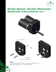
squarebot assembly<br />
In the Squarebot design, the Motion Subsystem is tightly<br />
integrated with the Structure Subsystem. The two systems<br />
are built together to form the “Chassis” of the Squarebot.<br />
Refer to the Squarebot Chassis Parts and Assembly section<br />
in the Structure chapter to see how the Motion and Structure<br />
subsystems are built in tandem.<br />
01/31/05<br />
3 • 2 Inventor’s <strong>Guide</strong>
motion<br />
concepts to understand<br />
Motors and Servomotors<br />
Motors are devices that can<br />
transform electrical energy<br />
into mechanical energy.<br />
That is, they take electrical<br />
power, and create physical<br />
motion. In the <strong>VEX</strong> system,<br />
they are further divided into<br />
two main types: standard motors<br />
and servomotors.<br />
The main difference is very<br />
clear and straightforward.<br />
Standard motors spin the<br />
attached axle around and<br />
around, while servomotors<br />
turn the axle to face a<br />
specific direction within their<br />
range of motion (120 degrees<br />
for the Vex servo module).<br />
TRANSMITTER<br />
COMMAND<br />
MOTOR<br />
BEHAVIOR<br />
Components<br />
SERVOMOTOR<br />
BEHAVIOR<br />
Note also that the Vex motor<br />
modules and Vex servo<br />
modules rotate their shafts in<br />
opposite directions, given the<br />
same transmitter command.<br />
This minor difference is due to<br />
the internal motor designs of<br />
the two different modules.<br />
For more information on radio<br />
control operation, see the<br />
Control Subsystem section of<br />
the Inventor’s <strong>Guide</strong>.<br />
01/31/05<br />
Inventor’s <strong>Guide</strong><br />
3 • 3
motion<br />
concepts to understand, continued<br />
Motors and Servomotors, continued<br />
Using Motors and Servos<br />
While similar in appearance,<br />
motors and servomotors are<br />
suited to distinctly different<br />
types of tasks.<br />
Motor Example:<br />
Main Drive Motors<br />
Regular motors should be<br />
used whenever continuous<br />
rotation is needed, such as in<br />
a robot’s main drive system.<br />
Servomotors can only be used<br />
in cases where the boundaries<br />
of motion are well-defined,<br />
but have the invaluable ability<br />
to self-correct to maintain<br />
any specific position within<br />
those boundaries.<br />
Use regular motors to power the robot’s drive wheels. The wheels<br />
need to make continuous full rotations, which is exactly the kind of<br />
motion provided by the motors.<br />
Servomotor Example:<br />
Directable Attachment Mounting<br />
Use a servomotor to<br />
control the facing of<br />
a platform on top of<br />
the robot (shown with<br />
a wireless camera for<br />
illustrative purposes).<br />
The servomotor allows<br />
you to turn the platform<br />
to face a specific<br />
direction relative to<br />
the robot, and will<br />
automatically hold that<br />
position until the controls<br />
are released.<br />
01/31/05<br />
3 • 4<br />
Inventor’s <strong>Guide</strong>
motion<br />
concepts to understand, continued<br />
Speed vs. Torque<br />
A motor can generate a set amount of power; that is, it can provide a<br />
specific amount of energy every second—this energy is most commonly<br />
used to make a wheel spin. Since there is only so much energy to go<br />
around, however, there is an inherent trade-off between Torque—the force<br />
with which the motor can turn the wheel—and Speed—the rate at which<br />
the motor can turn the wheel.<br />
The exact configuration of torque and speed is usually set using gears. By<br />
putting different combinations of gears between the motor and the wheel,<br />
the speed-torque balance will shift.<br />
Gears<br />
Gear Ratio<br />
You can think of gear ratio as<br />
a “multiplier” on torque and<br />
a “divider” on speed. If you<br />
have a gear ratio of 2:1, you<br />
have twice as much torque as<br />
you would if you had a gear<br />
ratio of 1:1, but only half as<br />
much speed.<br />
Calculating the gear ratio<br />
between a pair of gears is<br />
simple. First, identify which<br />
gear is the “driving” gear,<br />
and which is the “driven”<br />
gear. The “driving” gear is<br />
the one that is providing force<br />
to turn the other one. Often,<br />
this gear is attached directly<br />
to the motor axle. The other<br />
gear, the one that the driving<br />
gear is turning, is called the<br />
“driven” gear.<br />
To find gear ratio, you just<br />
need to count the number of<br />
teeth on the “driven” gear,<br />
and divide it by the number of<br />
teeth on the “driving” gear.<br />
01/31/05<br />
Inventor’s <strong>Guide</strong><br />
3 • 5
motion<br />
concepts to understand, continued<br />
Gears, continued<br />
Idler Gears<br />
Gears can be inserted<br />
between the driving and<br />
driven gears. These are called<br />
idler gears, and they have<br />
no effect on the robot’s gear<br />
ratio because their gear ratio<br />
contributions always cancel<br />
themselves out (because they<br />
are a driven gear relative to<br />
the first gear, and a driving<br />
gear relative to the last<br />
gear—you would first multiply<br />
by the number of teeth on<br />
the idler gear and then divide<br />
by the same number, which<br />
always cancels out).<br />
However, idler gears do<br />
reverse the direction of spin.<br />
Normally, the driving gear<br />
and the driven gear would<br />
turn in opposite directions.<br />
Adding an idler gear would<br />
make them turn in the same<br />
direction. Adding a second<br />
idler gear makes them turn in<br />
opposite directions again.<br />
Idler gears are typically used<br />
either to reverse the direction<br />
of spin between two gears, or<br />
to transmit force from one<br />
gear to another gear far away<br />
(by using multiple idler gears<br />
to physically bridge the gap).<br />
01/31/05<br />
3 • 6<br />
Inventor’s <strong>Guide</strong>
motion<br />
concepts to understand, continued<br />
Gears, continued<br />
Compound Gear Ratio<br />
Compound gears are formed<br />
when you have more than<br />
one gear on the same axle.<br />
Compound gears are not to be<br />
confused with idler gears, as<br />
compound gears can affect the<br />
overall gear ratio of a system!<br />
In the compound gear system,<br />
there are multiple gear pairs.<br />
Each pair has its own gear<br />
ratio, but the pairs are connected<br />
to each other by a<br />
shared axle.<br />
The resulting compound gear<br />
system still has a driving gear<br />
and a driven gear, and still<br />
has a gear ratio (now called a<br />
“compound gear ratio”).<br />
The compound gear ratio<br />
between the driven and driving<br />
gears is then calculated<br />
by multiplying the gear ratios<br />
of each of the individual gear<br />
pairs.<br />
Compound Gear Ratio:<br />
12:60 x 12:60 = 1:5 x 1:5 = 1:25<br />
Compound gears allow configurations with gear ratios that would not normally be achievable with<br />
the components available. In the example above, a compound gear ratio of 1:25 was achieved using<br />
only 12 and 60-tooth gears. This would give your robot the ability to turn an axle 25 times faster<br />
than normal (though it would only turn with 1/25th of the force)!<br />
01/31/05<br />
Inventor’s <strong>Guide</strong><br />
3 • 7
motion<br />
concepts to understand, continued<br />
Gears, continued<br />
Gear ratio with non-gear<br />
systems<br />
The real nature of gear ratios<br />
is a little more complex than<br />
just counting teeth on gears.<br />
Gear ratio is actually defined<br />
as the number of rotations<br />
that the driving axle needs<br />
to make in order to turn the<br />
driven axle around once.<br />
When dealing with toothed<br />
gears, you can find the number<br />
of turns needed by counting<br />
teeth, as you have already<br />
seen above (see “Gear ratio”).<br />
With other types of systems,<br />
you can still find the “gear ratio”<br />
by measuring the number<br />
of rotations on the driven and<br />
driving axles. Some of these<br />
other drive types include beltand-pulley<br />
drives and chainand-sprocket<br />
drives.<br />
Belt or chain drives are often<br />
preferred over gears when<br />
the motor and the wheel<br />
are located far apart on the<br />
robot. However, both belts<br />
and chains introduce their<br />
own special maintenance and<br />
performance requirements<br />
into the system (chains<br />
require lubrication and<br />
tension, for instance), and<br />
you should carefully weigh<br />
their advantages against other<br />
design considerations.<br />
01/31/05<br />
3 • 8<br />
Inventor’s <strong>Guide</strong>
motion<br />
concepts to understand, continued<br />
Wheels<br />
Wheel Sizes<br />
Often, the role of the motion subsystem on a robot will be to move the robot along the ground.<br />
The last step in the drive train, after the motors and gears, is the wheels.<br />
Like motors and gears, different properties of the wheel will affect your robot’s performance.<br />
The size of the wheels will be an important factor here, and will affect two distinct and<br />
different characteristics of the robot: its acceleration, and its top speed.<br />
Wheel Sizes and<br />
Acceleration<br />
The relationship between wheel<br />
size and acceleration is simple:<br />
bigger tires give you slower<br />
acceleration, while smaller tires<br />
give you faster acceleration.<br />
This relationship is the product<br />
of the physics of converting<br />
the spinning motion of a motor<br />
into the forward motion of the<br />
vehicle.<br />
Motors generate a “spinning”<br />
force (torque), which wheels<br />
convert into a “pushing” force<br />
at the point where they contact<br />
the ground. The larger this<br />
“pushing” force is, the faster<br />
the robot will accelerate.<br />
The relationship between torque<br />
and force is:<br />
Force = Torque<br />
Distance from Center<br />
to Edge of Wheel<br />
A longer distance between the<br />
center of the wheel and the<br />
ground will produce a smaller<br />
force for the same amount of<br />
torque, hence the larger wheel<br />
(which has the longer distance)<br />
has a smaller force, and hence<br />
the slower acceleration.<br />
01/31/05<br />
Inventor’s <strong>Guide</strong><br />
3 • 9
motion<br />
concepts to understand, continued<br />
Wheels, continued<br />
Wheel Sizes and Top Speed<br />
At top speed, robots with the<br />
same motor and gear ratio<br />
will generally travel with the<br />
motor running at the fastest<br />
speed it can spin. Robots<br />
may take some time to reach<br />
this speed, especially if they<br />
have high gear ratios (high<br />
gear ratio = low torque), but<br />
eventually, they tend to reach<br />
it, or at least come close.<br />
When a wheel rolls along<br />
the ground, it is effectively<br />
“unrolling” its circumference<br />
onto the surface it is<br />
traveling on, every time it<br />
goes around. Larger wheels<br />
have longer circumferences,<br />
and therefore “unroll”<br />
farther per rotation.<br />
Putting these two<br />
observations together, you<br />
can see that a robot with<br />
larger wheels will have a<br />
higher top speed. The robot<br />
with larger wheels goes<br />
farther with each turn of the<br />
wheels, and at top speed,<br />
robots with the same motor<br />
and gears will have their<br />
wheels turning the same<br />
number of times per second.<br />
Same number of turns times<br />
more distance per turn equals<br />
more distance, so the robot<br />
with larger wheels goes<br />
faster.<br />
Notice that this sets up a tough design decision, since you need to decide on<br />
a balance between acceleration and top speed when choosing a tire size. You<br />
can’t have it both ways, so you’ll need to plan ahead, decide which is more<br />
important to your robot, and choose wisely.<br />
01/31/05<br />
3 • 10<br />
Inventor’s <strong>Guide</strong>
motion<br />
concepts to understand, continued<br />
Wheels, continued<br />
Friction<br />
Friction occurs everywhere<br />
two surfaces are in contact<br />
with each other. It is most<br />
important when considering<br />
the wheels for your robot,<br />
however, because you will<br />
need to decide how much<br />
of it you want in order to<br />
maximize your robot’s<br />
performance.<br />
Wheel friction has both<br />
positive and negative<br />
consequences for your robot.<br />
On the one hand, friction<br />
between the wheel and<br />
the ground is absolutely<br />
essential in getting the<br />
robot to accelerate. Without<br />
friction, your robot would<br />
spin its wheels without<br />
going anywhere, like a car<br />
stuck on a patch of ice.<br />
Friction between the wheels<br />
and the ground gives the<br />
robot something to “push<br />
off” of when accelerating,<br />
decelerating, or turning.<br />
On the other hand, wheel<br />
friction is also responsible for<br />
slowing your robot down once<br />
it is moving. A robot running<br />
over a sticky surface will go<br />
slower than one running over<br />
a smooth one, because the<br />
friction dissipates some of the<br />
robot’s energy.<br />
The width, texture, and material of a tire all contribute to its<br />
friction characteristics. Wider, bumpier, or stickier tires will<br />
have more friction. Narrower, smoother, or slipperier tires will<br />
have less friction. Again, there is no “best” solution. Rather it is<br />
a matter of picking the tire best suited to the robot’s task.<br />
01/31/05<br />
Inventor’s <strong>Guide</strong><br />
3 • 11
motion<br />
concepts to understand, continued<br />
Wheels, continued<br />
Terrain<br />
On more difficult challenge<br />
courses, there will often be<br />
physical obstacles that must<br />
be traversed. Both the size<br />
of a tire and the amount of<br />
friction it generates will be<br />
very important in ensuring<br />
that you can successfully<br />
navigate them. These<br />
obstacles will be numerous<br />
and complex, so you will need<br />
to plan for them, and test<br />
your solutions to make sure<br />
that they work reliably.<br />
Example 1:<br />
Robot attempting to climb a step<br />
The robot with smaller wheels has a much steeper angle to climb<br />
– in fact, it’s a sheer vertical face.<br />
The robot with larger wheels has a much less difficult angle to climb<br />
to get up the step. This robot is much more likely to succeed.<br />
Example 2:<br />
Robots attempting to climb a gravel hill<br />
The robot with slippery<br />
tires cannot get enough<br />
traction to climb the hill<br />
and slides off.<br />
The robot with better<br />
traction can make it up<br />
the hill.<br />
01/31/05<br />
3 • 12<br />
Inventor’s <strong>Guide</strong>
motion<br />
concepts to understand, continued<br />
Clutches<br />
Clutches<br />
Every motor in the Vex<br />
Starter Kit comes with a<br />
pre-attached clutch module.<br />
The clutch module’s purpose<br />
is to prevent damage to the<br />
motor’s internal gearing<br />
by temporarily breaking<br />
the connection between the<br />
motor and its attached wheel<br />
or gear whenever there is<br />
too much resistance. This<br />
prevents the motor from<br />
entering the potentially<br />
damaging stall (motor can’t<br />
turn) or<br />
back-driving (motor is<br />
being forced backwards)<br />
conditions.<br />
The motor clutches are<br />
removable for maintenance<br />
reasons, but should always<br />
be replaced immediately<br />
afterwards. Do not attempt<br />
to operate the motors without<br />
the clutches installed.<br />
01/31/05<br />
Inventor’s <strong>Guide</strong><br />
3 • 13
motion<br />
concepts to understand, continued<br />
Motion Part Features<br />
Hub Tire<br />
The small green tires in the<br />
kit are actually two tires in<br />
one. By pulling off the rubbery<br />
green tire surface, the<br />
grey hubs can be used directly<br />
as a set of very small, lowfriction<br />
tires for your robot.<br />
Non-Axial Mounting Points<br />
(60-tooth gear)<br />
In addition to the central<br />
hole for the gear shaft, the<br />
60-tooth gear (and 84-tooth<br />
gear, available separately)<br />
have a number of additional<br />
off-center mounting holes.<br />
These mounting points have<br />
a number of applications. For<br />
instance, a larger structure<br />
could be built on top of the<br />
gear, which would rotate as<br />
the gear turned. Alternately,<br />
the “orbiting” motion of a<br />
non-axial mount can be used<br />
to create linear motion from<br />
rotational motion.<br />
01/31/05<br />
3 • 14<br />
Inventor’s <strong>Guide</strong>
motion<br />
concepts to understand, continued<br />
Motor Gear Replacement<br />
Gear Wear and Tear<br />
Gears are simple plastic<br />
components, but they often<br />
bear tremendous amounts of<br />
stress in a moving system.<br />
The gears inside the motors,<br />
in particular, are subjected<br />
to large amounts of wear and<br />
tear during use in robotics<br />
applications where they are<br />
frequently required to reverse<br />
direction quickly (to make the<br />
robot go the other way, for<br />
instance).<br />
Inevitably, these gears<br />
will wear out and need<br />
replacement. The Vex Starter<br />
Kit includes replacement<br />
gears for the internal motor<br />
gears (and you can buy<br />
more), so you can perform<br />
the necessary repairs when<br />
needed.<br />
To replace the gears in a<br />
motor or servomotor, follow<br />
these instructions.<br />
1. (top of page) Remove the<br />
clutch and clutch post.<br />
2. Remove the four screws in<br />
the corners of the front of the<br />
motor case.<br />
01/31/05<br />
Inventor’s <strong>Guide</strong><br />
3 • 15
motion<br />
concepts to understand, continued<br />
Sturdiness, Motor Gear continued Replacement, continued<br />
3. Gently lift off the top cover.<br />
Try to do so without disturbing<br />
the gears inside, so you can see<br />
the proper configuration for<br />
later reference.<br />
4. Remove the middle gear and<br />
the large shaft gear together.<br />
*Be careful when handling<br />
gears, as they are coated with<br />
a layer of lubricant that helps<br />
them turn smoothly. Wash your<br />
hands after handling the gears!<br />
01/31/05<br />
3 • 16<br />
Inventor’s <strong>Guide</strong>
motion<br />
concepts to understand, continued<br />
Motor Gear Replacement, continued<br />
5. Remove the side gear.<br />
6. Remove the thin bottom gear.<br />
7. Open the packaging for the<br />
replacement gears. Take special<br />
care when handling the<br />
replacement gears, as they are<br />
very small and slippery<br />
(they come pre-greased).<br />
Note: The large black servo motor<br />
gear will have a black plastic key<br />
underneath the gear’s metal<br />
bushing. (Not shown)<br />
01/31/05<br />
Inventor’s <strong>Guide</strong><br />
3 • 17
motion<br />
concepts to understand, continued<br />
Motor Gear Replacement, continued<br />
8. Install the replacement thin<br />
bottom gear.<br />
9. Install the replacement<br />
side gear.<br />
10. Install the replacement middle<br />
gear and the replacement large gear<br />
together, the same way you took<br />
them apart.<br />
01/31/05<br />
3 • 18<br />
Inventor’s <strong>Guide</strong>
motion<br />
concepts to understand, continued<br />
Motor Gear Replacement, continued<br />
11. Carefully replace the<br />
top cover. Don’t disturb the<br />
gears, or the motor may<br />
not turn properly.<br />
12. Replace the four<br />
corner screws.<br />
01/31/05<br />
Inventor’s <strong>Guide</strong><br />
3 • 19
motion<br />
concepts to understand, continued<br />
Motor Gear Replacement, continued<br />
13. Replace the clutch<br />
and clutch shaft.<br />
01/31/05<br />
3 • 20<br />
Inventor’s <strong>Guide</strong>
motion<br />
subsystem interactions<br />
How does the Motion Subsystem<br />
interact with…<br />
…the Structure Subsystem?<br />
• The motion and structure subsystems are tightly<br />
integrated in many robots designs, including the<br />
Squarebot. The motion subsystem can’t be<br />
constructed without certain structural components<br />
(like the chassis rails) to provide support and<br />
positional reference. By the same token, the structure<br />
subsystem must be designed largely to accommodate<br />
the motion components.<br />
• On Squarebot, the structure and motion<br />
subsystems are so interconnected that you cannot<br />
build them separately. Hence, they are constructed<br />
together in the Chassis building instructions (which<br />
can be found in the Structure Subsystem chapter).<br />
…the Power Subsystem?<br />
• The Motion Subsystem’s motors and servomotors<br />
convert electrical energy into physical energy, and so<br />
they will of course need electrical energy to work<br />
with. This energy is ultimately supplied by the Power<br />
Subsystem’s batteries, but the motors do not plug<br />
into the batteries directly. Rather, the flow of power<br />
is directed by the Micro Controller, which decides<br />
how much power is allowed to flow from the Power<br />
Subsystem to the Motion components.<br />
…the Control Subsystem?<br />
• Unlike radio-controlled cars, the Vex robot does<br />
not directly tie the Control Subsystem into<br />
the Motion Subsystem. The commands generated<br />
by the operator using the Transmitter are sent to<br />
the RF receiver on the robot, but from there, the<br />
commands are given to the Micro Controller,<br />
which takes this and other information into<br />
account when deciding which command to give to<br />
the Motion components.<br />
… the Logic Subsystem?<br />
• The Motion Subsystem plugs into the Micro<br />
Controller, which is the main component in the<br />
Logic Subsystem. Though the Motion components<br />
are “controlled” to various degrees by user input<br />
(Control Subsystem) and sensor feedback (Sensor<br />
Subsystem), the final decision on what command<br />
is issued, as well as the actual flow of electricity<br />
(from the Power Subsystem) is all controlled by<br />
the Logic Subsystem. The Logic Subsystem<br />
governs everything the Motion components do.<br />
…the Sensor Subsystem?<br />
• Robots often have motors and other Motion<br />
components controlled by sensors (for instance, the<br />
emergency stop function stops the motors when the<br />
bumper switch sensor is pushed). However, the<br />
Sensor Subsystem does not directly control the<br />
Motion Subsystem. Instead, the Sensors provide<br />
information to the Micro Controller, which takes that<br />
information into account, and then decides what<br />
command to send to the Motion Subsystem.<br />
01/31/05<br />
Inventor’s <strong>Guide</strong><br />
3 • 21
motion<br />
motion subsystem inventory<br />
component<br />
qty<br />
component<br />
qty<br />
motor assembly 3<br />
2.75" 4<br />
removable tire<br />
servo motor 1<br />
1.895" hub for 4<br />
removable tire<br />
replacement gears 2<br />
(4/set)<br />
all purpose 2<br />
tire (4")<br />
screw 6-32 x ¼" 4<br />
screw 6-32 x ½" 4<br />
clutch post 4<br />
01/31/05<br />
3 • 22<br />
Inventor’s <strong>Guide</strong>
motion<br />
motion subsystem inventory, continued<br />
component qty component qty<br />
knobby tire (5") 2<br />
60 tooth gear 4<br />
intake roller 2<br />
12 tooth gear 4<br />
36 tooth gear 4<br />
01/31/05<br />
Inventor’s <strong>Guide</strong><br />
3 • 23
motion accessories<br />
gear kit<br />
Gear Kit<br />
This kit contains additional gears so you will always have<br />
the right combination available to ensure you can achieve<br />
the desired balance of torque, speed, and direction. All the<br />
parts included in this kit were also included in the Starter<br />
Kit, with the exception of the 84-tooth gear, which is just<br />
like the other gears, except with more teeth, which gives you<br />
access to even higher (or lower) gear ratios.<br />
INSERT THIS PAGE<br />
at the back of the<br />
Motion Chapter in your<br />
Vex Inventor’s <strong>Guide</strong>.<br />
To expand your inventing possibilities, the 60- and 84-tooth<br />
gears have extra mounting holes. These mounting holes can<br />
be used for attaching metal bars or parts to these gears<br />
when using them as part of a turntable system, or other<br />
similar designs. Consult your Vex Inventor’s <strong>Guide</strong> for<br />
building tips and examples on how to use gears to change<br />
the speed/torque balance and direction of your robot’s drive<br />
train spin.<br />
Limited 90-day Warranty<br />
This product is warranted by Innovation<br />
One against manufacturing<br />
defects in material and workmanship<br />
under normal use for ninety (90)<br />
days from the date of purchase from<br />
authorized Innovation One dealers.<br />
For complete warranty details and<br />
exclusions, check with your dealer.<br />
Innovation One, Inc.<br />
350 North Henderson Street<br />
Fort Worth, TX 76102<br />
11/04<br />
Printed in China<br />
0105<br />
12-tooth gear x 4<br />
36-tooth gear x 4<br />
60-tooth gear x 4 84-tooth gear x 2<br />
accessories<br />
Inventor’s <strong>Guide</strong> insert<br />
gear kit • 1<br />
© 2005 Innovation One. All Rights Reserved. Vex and Vex <strong>Robotics</strong> Design System are trademarks of Innovation One.
motion accessories<br />
motor kit<br />
Motor and four-wheel drive (4WD) Kit<br />
As explained in the Motion Subsystem section of the<br />
Inventor’s <strong>Guide</strong>, standard motors convert electrical energy<br />
into mechanical energy by spinning either forward or<br />
backward at a controlled speed.<br />
INSERT THIS PAGE<br />
at the back of the<br />
Motion Chapter in your<br />
Vex Inventor’s <strong>Guide</strong>.<br />
Now that you have four motors, your robot no longer needs<br />
to rely on a single motor to turn both the front and rear<br />
wheels on the same side of the robot. You can now use one<br />
motor for each wheel, and have twice as much torque<br />
available for your robot to tackle increasingly difficult<br />
terrain.<br />
The Vex Robot Micro-Controller already has the ability to<br />
support this four-wheel drive mode. All you need to do is<br />
place a jumper clip on the appropriate Analog/Digital<br />
port, and your robot will work with all four motors. See<br />
Appendix F in the original Vex Starter Kit Inventor’s<br />
<strong>Guide</strong> for details.<br />
Limited 90-day Warranty<br />
This product is warranted by Innovation One<br />
against manufacturing defects in material and<br />
workmanship under normal use for ninety (90)<br />
days from the date of purchase from authorized<br />
Innovation One dealers. For complete warranty<br />
details and exclusions, check with your dealer.<br />
Innovation One, Inc.<br />
350 North Henderson Street<br />
Fort Worth, TX 76102<br />
11/04<br />
Printed in China<br />
0105<br />
motor x 1<br />
replacement gears x 2<br />
screw 6-32 x ½" x 2<br />
screw 6-32 x ¼" x 2<br />
clutch post x 1<br />
accessories<br />
Inventor’s <strong>Guide</strong> insert<br />
motor kit • 1<br />
© 2005 Innovation One. All Rights Reserved. Vex and Vex <strong>Robotics</strong> Design System are trademarks of Innovation One.
motion accessories<br />
servomotor kit<br />
Servomotor<br />
As explained in the Motion Subsystem section of the<br />
Inventor’s <strong>Guide</strong>, servomotors are a type of motor that can<br />
be directed to turn to face a specific direction, rather than<br />
just spin forward or backward.<br />
INSERT THIS PAGE<br />
at the back of the<br />
Motion Chapter in your<br />
Vex Inventor’s <strong>Guide</strong>.<br />
Limited 90-day Warranty<br />
This product is warranted by Innovation One<br />
against manufacturing defects in material and<br />
workmanship under normal use for ninety (90)<br />
days from the date of purchase from authorized<br />
Innovation One dealers. For complete warranty<br />
details and exclusions, check with your dealer.<br />
Innovation One, Inc.<br />
350 North Henderson Street<br />
Fort Worth, TX 76102<br />
11/04<br />
Printed in China<br />
0105<br />
servomotor x 1<br />
replacement gears x 2<br />
screw 6-32 x ½" x 2<br />
screw 6-32 x ¼" x 2<br />
clutch post x 1<br />
accessories<br />
Inventor’s <strong>Guide</strong> insert<br />
servomotor kit • 1<br />
© 2005 Innovation One. All Rights Reserved. Vex and Vex <strong>Robotics</strong> Design System are trademarks of Innovation One.
motion accessories<br />
wheel kit<br />
Wheel Kit<br />
This kit contains additional wheels that will help your robot<br />
get a better grip on any situation. All the parts included in<br />
this kit were also included in your Vex Starter Kit, so<br />
consult the Vex Inventor’s <strong>Guide</strong> for building tips and<br />
examples on how to use them.<br />
INSERT THIS PAGE<br />
at the back of the<br />
Motion chapter in your<br />
Vex Inventor’s <strong>Guide</strong>.<br />
Limited 90-day Warranty<br />
This product is warranted by Innovation One<br />
against manufacturing defects in material and<br />
workmanship under normal use for ninety (90)<br />
days from the date of purchase from authorized<br />
Innovation One dealers. For complete warranty<br />
details and exclusions, check with your dealer.<br />
Innovation One, Inc.<br />
350 North Henderson Street<br />
Fort Worth, TX 76102<br />
11/04<br />
Printed in China<br />
0105<br />
intake roller x 2<br />
2.75" removable tire x 4<br />
1.895" hub for removable<br />
tire x 4<br />
all-purpose tire x 2 knobby tire x 2<br />
accessories<br />
Inventor’s <strong>Guide</strong> insert<br />
wheel kit • 1
Power is vital to the<br />
operation of all the<br />
electronic parts on the<br />
robot, including the<br />
controller and the motors.<br />
With the structural<br />
subsystem as the robot’s<br />
skeleton, and the motion<br />
subsystem as the muscle,<br />
the power subsystem is<br />
the circulatory system—<br />
the heart and blood<br />
vessels that provide the<br />
rest of the robot with<br />
energy.<br />
power
power<br />
power<br />
table of contents:<br />
squarebot parts & assembly 4.2<br />
concepts to understand 4.7<br />
subsystems interactions 4.17<br />
power subsystem inventory 4.18<br />
01/31/05<br />
Inventor’s <strong>Guide</strong><br />
4 • 1
power<br />
squarebot parts & assembly<br />
squarebot assembly<br />
Vex robots use batteries as their source of energy.<br />
The power subsystem is comprised of batteries and the other<br />
components needed to support them.<br />
Tips for battery use (see Battery Types and Battery Care<br />
in the Concepts to Understand section for details):<br />
• Buy a Vex Power Pack or a good set of rechargeable AA<br />
batteries (more than one set if you want to be able to use<br />
the robot while the other set is charging)<br />
• Buy a good battery charger<br />
• Charge batteries fully before first use<br />
• Dispose of batteries properly – not in the trash!<br />
1 Collect and identify the parts<br />
from the list of materials below:<br />
materials<br />
qty<br />
NiCd AA battery 14<br />
battery holder with lid 1<br />
transmitter battery box 1<br />
keps nut 4<br />
8-32 hex screw, 3 /8" 4<br />
01/31/05<br />
4 • 2 Inventor’s <strong>Guide</strong>
power<br />
squarebot assembly<br />
squarebot parts & assembly, continued<br />
AA battery x 14<br />
battery holder w/ lid x 1<br />
transmitter battery box x 1<br />
8-32 hex screw, 3 /8" x 4<br />
keps nut x 4<br />
01/31/05<br />
Inventor’s <strong>Guide</strong><br />
4 • 3
power<br />
squarebot assembly<br />
squarebot power parts and assembly, continued<br />
2 For Transmiter Assembly:<br />
Open the battery lid.<br />
Insert 8 AA batteries, paying close<br />
attention to the battery orientation<br />
indicated on the holder.<br />
Close the lid.<br />
01/31/05<br />
4 • 4 Inventor’s <strong>Guide</strong>
power<br />
squarebot assembly<br />
squarebot power parts and assembly, continued<br />
3 For the Squarebot Battery Holder:<br />
Remove the battery lid.<br />
Insert batteries, paying close<br />
attention to the battery orientation<br />
indicated on the holder.<br />
01/31/05<br />
Inventor’s <strong>Guide</strong><br />
4 • 5
power<br />
squarebot assembly<br />
squarebot power parts and assembly, continued<br />
4 Positioning the Battery Holder<br />
on Squarebot:<br />
Position the battery holder without the<br />
lid on top of the Squarebot.<br />
Keep the lid off until the screws<br />
that secure the holder are in place.<br />
Attach holder using four 3 /8" screws.<br />
The final assembly should look<br />
like this:<br />
01/31/05<br />
4 • 6 Inventor’s <strong>Guide</strong>
power<br />
concepts to understand<br />
Battery Power Indicators<br />
Since there are two sets of<br />
batteries in the Vex system,<br />
there are two battery power<br />
indicators.<br />
One is on the Transmitter,<br />
and displays the battery<br />
voltage remaining in the<br />
transmitter unit.<br />
Transmitter LED<br />
Indicates…<br />
displayed voltage<br />
9.4V Transmitter batteries somewhat low. You<br />
will need to stop soon.<br />
8.9V Transmitter batteries very low (10<br />
minutes or less remaining), stop unless<br />
absolutely necessary.<br />
8.5V Transmitter batteries depleted. Stop now.<br />
The other indicator is the<br />
Batt. Power light on the<br />
front of the Micro Controller,<br />
which tells you when the<br />
batteries on board the robot<br />
need to be recharged.<br />
Battery Power Light<br />
Color<br />
Green<br />
Red<br />
Indicates…<br />
Onboard robot batteries are OK.<br />
Onboard batteries need to be recharged.<br />
01/31/05<br />
Inventor’s <strong>Guide</strong><br />
4 • 7
power<br />
concepts to understand, continued<br />
Battery Types<br />
Due to the large amount of<br />
current that the robot will<br />
draw from the batteries, we<br />
recommend NiCd batteries<br />
for use with the Vex robot.<br />
<strong>VEX</strong> Power Pack<br />
The best way to provide for<br />
the energy needs of the Vex<br />
robot is with the Vex battery.<br />
The Vex Power Pack includes<br />
a 7.2V battery pack for the<br />
robot, a 9.6V battery pack<br />
for the radio transmitter unit,<br />
and a charger for both batteries.<br />
The batteries are NiCd<br />
(Nickel-Cadmium chemical<br />
composition) rechargeables<br />
that provide significantly<br />
energy than comparable AA<br />
NiCd batteries.<br />
The Vex Power Pack<br />
cells, will provide a<br />
constant reliable voltage<br />
until they are exhausted.<br />
Contrary to popular belief,<br />
NiCd batteries do not suffer<br />
from any sort of permanent<br />
“memory effect” (see Battery<br />
Care later in this chapter).<br />
For installation instructions,<br />
consult the documentation<br />
included with the Vex<br />
Power Pack.<br />
01/31/05<br />
4 • 8<br />
Inventor’s <strong>Guide</strong>
power<br />
concepts to understand, continued<br />
Battery Types, continued<br />
NiCd Rechargeable<br />
AA batteries<br />
NiCd (Nickel-Cadmium<br />
chemical composition)<br />
AA batteries are<br />
recommended for use in<br />
the Vex <strong>Robotics</strong> Design<br />
System. Modern NiCd<br />
batteries do not suffer<br />
from any sort of<br />
permanent memory<br />
effect.<br />
You will need to purchase<br />
six AA batteries for the<br />
Micro Controller and<br />
eight AA batteries for the<br />
Transmitter (14 batteries<br />
total). You will also need to<br />
purchase an NiCd battery<br />
recharger (be sure to get one<br />
that specifically) charges<br />
NiCd batteries).<br />
For battery installation<br />
instructions, see the<br />
beginning of this chapter.<br />
Note: Disposing of NiCd<br />
rechargeable batteries in the<br />
trash is illegal in many<br />
countries and states.<br />
01/31/05<br />
Important: The EPA certified RBRC® Battery Recycling Seal on<br />
the nickel-cadmium (NiCd) battery indicates Innovation One voluntarily<br />
participates in an industry program to collect and recycle these batteries at<br />
the end of their useful life, when taken out of service in the United States or<br />
Canada. The RBRC program provides a convenient alternative to placing used<br />
NiCd batteries into the trash or the municipal waste stream, which may be<br />
illegal in your area. Please call 1-800-8-BATTERY for information on<br />
NiCd battery recycling and disposal bans/restrictions in your area.<br />
Innovation One’s involvement in this program is part of the company’s<br />
commitment to preserving our environment and conserving our<br />
natural resources.<br />
Inventor’s <strong>Guide</strong><br />
4 • 9
power<br />
concepts to understand, continued<br />
Battery Types, continued<br />
Alkaline Rechargeble<br />
and Non-rechargeable<br />
AA batteries<br />
Alkaline batteries are NOT<br />
RECOMMENDED for the Vex<br />
<strong>Robotics</strong> Design System, but<br />
can be used in the transmitter.<br />
Alkaline technology was not<br />
designed to handle the high<br />
levels of current that a<br />
robot requires (i.e. they<br />
cannot provide power fast<br />
enough), so the robot may<br />
lose power and turn off at<br />
unpredictable times.<br />
Alkaline batteries also provide<br />
a decreasing voltage as they<br />
are used up, so the level of<br />
power available to the robot<br />
falls as the batteries are<br />
drained.<br />
Alkaline<br />
Alkaline<br />
Alkaline<br />
Alkaline<br />
Alkaline<br />
Alkaline<br />
Alkaline<br />
Alkaline<br />
Alkaline<br />
Alkaline<br />
Alkaline<br />
Alkaline<br />
Alkaline<br />
Alkaline<br />
NiCd batteries maintain their<br />
voltages reliably until they<br />
are almost completely empty.<br />
Finally, alkaline batteries,<br />
even “rechargeable” ones,<br />
are not truly rechargeable<br />
(rechargeable alkalines lose<br />
power with every recharge,<br />
and need to be replaced<br />
frequently). This means that<br />
their replacement cost will<br />
become prohibitive over time.<br />
This includes the newer<br />
alkaline batteries that claim<br />
to be “designed for use in<br />
high tech devices,” but still<br />
suffer from the same<br />
drawbacks which make all<br />
alkaline batteries impractical<br />
for robot use.<br />
01/31/05<br />
4 • 10<br />
Inventor’s <strong>Guide</strong>
power<br />
concepts to understand, continued<br />
Battery Care<br />
First Use<br />
If you are using rechargeable batteries (and you should be!), remember<br />
to let them charge fully the first time before you use them because they<br />
are usually shipped uncharged. Be sure to let them reach full capacity in<br />
order to ensure a healthy battery charging cycle.<br />
Memory Effect and Voltage Drop<br />
A myth that often surfaces about rechargeable batteries is the “memory<br />
effect”. This refers to a mistaken belief that total battery capacity<br />
diminishes permanently by a failure to drain the battery to zero voltage<br />
and then recharge it to full. “Memory effect” does not exist in consumer<br />
devices, only in very specific laboratory conditions.<br />
A real phenomenon called “voltage drop” does exist that can easily be<br />
mistaken for the fictitious “memory effect.” Voltage drop is a<br />
measurable phenomenon where a battery that is repeatedly “shallow<br />
discharged” (used only part way before recharging) will start delivering<br />
lower and lower voltages, and will run out sooner.<br />
Discharge Cycles<br />
The good news about voltage drop is that it is not permanent, and it is<br />
curable. If your batteries seem to be getting shorter life than usual, all<br />
you need to do is run them down until the Vex Robot Micro Controller<br />
automatically turns off, or the transmitter displays its low voltage<br />
warning (this will happen between 1 and 1.1V per cell—6.5V for the<br />
robot, 8.5V for the transmitter), then charge them back to full again.<br />
You may need to perform the drain/recharge process a few times, but<br />
your batteries should steadily improve in performance each time until<br />
they are back to full strength.<br />
Never discharge a NiCd cell to less than .9-1.0V. By not discharging the<br />
batteries farther than this (known as “deep cycling”), you will avoid a<br />
condition that could potentially damage your batteries and/or charger.<br />
01/31/05<br />
Inventor’s <strong>Guide</strong><br />
4 • 11
power<br />
concepts to understand, continued<br />
Battery Care, continued<br />
Overcharge/Trickle Charge<br />
In addition to not excessively draining rechargeable batteries, you should<br />
also avoid overcharging them. Overcharging can cause permanent<br />
damage to the battery. It is important that you get a good NiCd charger<br />
that knows when to stop adding charge to the batteries. Once the<br />
battery has reached full charge, the charger should switch over into<br />
“trickle charge” mode, which is a low current mode that can be safely<br />
applied over a long period of time to maintain a full charge, or shut off<br />
the charger.<br />
Temperature<br />
Charging or draining batteries quickly will result in them heating up.<br />
Excessive heat can also cause permanent damage to the battery, and<br />
should be avoided. Also do not store batteries in high temperature<br />
conditions. If batteries are hot after charging or running, let them cool<br />
down before charging or running.<br />
Age<br />
Rechargeable NiCd batteries can be used over and over again for hundreds<br />
of battery cycles if properly maintained. However, all batteries will<br />
eventually wear out over time, and you should keep in mind that if you<br />
notice an old set of batteries is not performing as well as it used to, it<br />
may be time to get a fresh set.<br />
Environmental Issues<br />
The cadmium found in NiCd batteries is highly toxic, and should not be<br />
disposed of in the trash. It is illegal to do so in many countries and states.<br />
Check your local regulations for information on proper battery recycling<br />
procedures in your area.<br />
01/31/05<br />
4 • 12<br />
Inventor’s <strong>Guide</strong>
power<br />
concepts to understand, continued<br />
Voltage and Energy<br />
Any time something in the<br />
physical world has the<br />
potential to go from one<br />
location to another there is an<br />
opportunity for it to do some<br />
useful work along the way.<br />
When water runs over a cliff,<br />
it falls downward because<br />
gravity is pulling on it. A<br />
hydroelectric generator takes<br />
advantage of this by having<br />
the water turn a turbine along<br />
the way as it falls<br />
High<br />
Energy<br />
Low<br />
Energy<br />
When the water was up on<br />
top of the cliff, it had a lot<br />
of “gravitational potential<br />
energy”, energy that was<br />
stored in the water because<br />
it was high up even though<br />
gravity wanted to pull it<br />
downwards. After falling to<br />
the bottom of the cliff, it got<br />
rid of some of its gravitational<br />
potential energy. Normally,<br />
the energy that was given up<br />
by the water is wasted (it gets<br />
transformed into other forms<br />
of energy, like sound and heat<br />
as the water hits the bottom),<br />
but if the water runs through<br />
a hydroelectric generator, the<br />
generator instead takes the<br />
energy and transforms it into<br />
a form that is useful to us, as<br />
electrical energy.<br />
High<br />
Energy<br />
Lost<br />
Energy<br />
Low<br />
Energy<br />
High<br />
Energy<br />
Low<br />
Energy<br />
01/31/05<br />
Inventor’s <strong>Guide</strong><br />
4 • 13
power<br />
concepts to understand, continued<br />
Voltage and Energy, continued<br />
Electrons have negative<br />
charges, and naturally move<br />
toward areas with positive<br />
charges because opposite<br />
charges attract. A battery<br />
is like the cliff. One end (the<br />
– side) holds electrons at an<br />
area where they have high<br />
potential energy, just like<br />
the top of the cliff. The other<br />
side (the + end) is like the<br />
bottom of the cliff, an area of<br />
low potential energy that the<br />
electrons would like to travel<br />
toward. “Voltage” is the term<br />
used to describe the difference<br />
in electrical potential energy<br />
between two regions, hence a<br />
1.5V battery has 1.5 volts of<br />
difference between the region<br />
at the + end and the region<br />
at the – end.<br />
Unlike the waterfall, however,<br />
the battery doesn’t just let<br />
the electrons travel freely<br />
from the high-energy end<br />
to the low-energy end. You<br />
need to provide a path for the<br />
electrons in order to let them<br />
get from one end to the other<br />
by connecting the battery to<br />
a circuit. The wire provides a<br />
path for electrons to get from<br />
the – side to the + side.<br />
Warning:<br />
Never hook a wire directly<br />
from one end of a battery<br />
to the other as the battery<br />
will become extremely hot.<br />
High Energy<br />
e<br />
e<br />
e<br />
e e<br />
e<br />
e<br />
e e<br />
e<br />
Low Energy<br />
High Energy<br />
e e e<br />
e<br />
e<br />
e<br />
–<br />
+<br />
e<br />
e<br />
e<br />
e<br />
e<br />
e<br />
e<br />
e<br />
e<br />
e<br />
e<br />
e<br />
e<br />
e<br />
e<br />
Low Energy<br />
01/31/05<br />
4 • 14<br />
Inventor’s <strong>Guide</strong>
power<br />
concepts to understand, continued<br />
Voltage and Energy, continued<br />
The last step in the process<br />
is to add the hydroelectric<br />
generator. Except instead<br />
of a generator, you will be<br />
harvesting the energy from<br />
the moving electrons, with<br />
motors that change the<br />
electrical energy into physical<br />
energy and computer chips<br />
that use the energy to power<br />
other circuits inside them.<br />
This is, of course, a huge<br />
simplification of the way<br />
electricity really works<br />
in a circuit, but the ideas<br />
behind voltage should still be<br />
clear: that there are regions<br />
with different amounts of<br />
potential energy, that the<br />
battery is what maintains that<br />
difference, and that the rest<br />
of the electronic components<br />
in the robot are effectively<br />
drawing their power from<br />
the electrons that are trying<br />
to move from one region to<br />
the other.<br />
High Energy<br />
e e e<br />
e<br />
e<br />
e<br />
–<br />
+<br />
e<br />
e<br />
e<br />
e<br />
e<br />
e<br />
e<br />
e<br />
e<br />
e<br />
e<br />
e<br />
e<br />
e<br />
e<br />
Low Energy<br />
01/31/05<br />
Inventor’s <strong>Guide</strong><br />
4 • 15
power<br />
concepts to understand, continued<br />
Voltage and Energy, continued<br />
Batteries in Series<br />
Batteries can be stacked together in series to add their voltages together, like<br />
stacking cliffs to make a bigger cliff. This is how multiple AA batteries (which<br />
are 1.2-1.5V each) produce a single larger “battery pack” with a combined<br />
voltage of around 7.2V in the Vex system. The Transmitter does the same<br />
thing to achieve a voltage of 9.6V.<br />
Battery Cells<br />
Individual batteries (like a single AA) are often called “cells,” to distinguish<br />
them from the entire “battery” pack. Technically, a “battery” refers strictly<br />
to a collection of multiple cells, so what we have been referring to as a<br />
battery pack is a “battery”, and what we usually call a battery (like an AA<br />
battery) is technically not a battery, but a “cell”.<br />
The word “cell” comes from the nature of the battery as a self-contained<br />
vessel for the chemical reaction necessary to produce a specific electrical<br />
voltage. The name comes from an early 1800’s battery design by Dr. William<br />
Cruickshank, in which a wooden box or trough was divided into “cells,” and<br />
each cell had a metal plate inserted into it to create the electrochemical<br />
reaction. A modern battery pack (multiple AAs in series, for instance),<br />
similarly, has multiple “cells” with separate chemical chambers, which work<br />
together to produce the overall “battery” voltage.<br />
01/31/05<br />
4 • 16<br />
Inventor’s <strong>Guide</strong>
power<br />
subsystem interactions<br />
How does the Power Subsystem<br />
interact with…<br />
…the Structure Subsystem?<br />
• The structure subsystem generally provides<br />
a safe, protected place to secure the battery.<br />
• On the Squarebot, the structure subsystem<br />
provides a mounting platform for the batter<br />
holder, on the underside of the chassis<br />
(see Power Subsystem building instructions).<br />
…the Motion Subsystem?<br />
• The Motion Subsystem’s motors and servomotors<br />
convert electrical energy into physical energy,<br />
and so they will of course need electrical energy<br />
to work with. This energy is ultimately supplie<br />
by the Power Subsystem’s batteries, but the<br />
motors do not plug into the batteries directly.<br />
Rather, the flow of power is directed by the<br />
Micro Controller, which decides how much power<br />
is allowed to flow from the Power Subsystem to<br />
the Motion components.<br />
…the Sensor Subsystem?<br />
• Sensors, like all electronic components, require<br />
power in order to function. Vex sensors draw<br />
power indirectly from the Power Subsystem<br />
through the Micro Controller (Logic Subsystem).<br />
…the Control Subsystem?<br />
• Broadcasting radio waves takes a significant<br />
amount of electrical power. The eight AA batteries<br />
(or 9.6V battery pack) installed in the Vex<br />
Transmitter provide the Transmitter with all the<br />
power it needs to operate its internal circuitry and<br />
send out radio waves carrying commands to the<br />
receiver.<br />
• The RF Receiver module mounted onboard the<br />
robot, on the other hand, draws its power from the<br />
Power Subsystem indirectly, through the Micro<br />
Controller (which is part of the Logic Subsystem).<br />
… the Logic Subsystem?<br />
• Since the Micro Controller is a device<br />
that contains a large number of electronic<br />
components, including two computer<br />
microprocessors, it needs power, which it<br />
draws directly from its connection to the<br />
Power Subsystem.<br />
• The other major function of the Micro Controller<br />
is to control the other subsystems on the<br />
robot. It does this by selectively routing powe<br />
from the Power Subsystem batteries to the other<br />
subsystems’ components (like motors).<br />
• The Power Subsystem battery holder (or battery<br />
pack) connects to the Micro Controller module<br />
using a two-pin connector inside a plastic<br />
housing, which is mechanically “keyed” to<br />
prevent it from being plugged in backward.<br />
01/31/05<br />
Inventor’s <strong>Guide</strong><br />
4 • 17
power<br />
power subsystem inventory<br />
component<br />
qty<br />
battery holder 1<br />
with lid<br />
01/31/05<br />
4 • 18 Inventor’s <strong>Guide</strong>
power accessories<br />
Vex power pack<br />
The Vex Power Pack is designed to provide reliable highperformance<br />
power for the Vex <strong>Robotics</strong> Design System. The kit<br />
includes one 9.6V NiCd rechargeable battery pack for the RF<br />
Transmitter, one 7.2V NiCd rechargeable battery pack for the<br />
Micro Controller, and a charger that can charge either battery<br />
safely in 3 hours or less (6 hours for both batteries). See the<br />
Power Subsystem in the Inventor’s <strong>Guide</strong> for information on<br />
battery care.<br />
In case you need even more power, you can purchase additional<br />
rechargeable batteries at your local electronics retailer.<br />
9.6V Transmitter<br />
Power Pack x 1<br />
Battery Charger x 1<br />
7.2V Robot<br />
Power Pack x 1<br />
INSERT THESE PAGES<br />
at the back of the<br />
Power Chapter in your<br />
Vex Inventor’s <strong>Guide</strong>.<br />
accessories<br />
Reusable Battery Strap<br />
(for 7.2V battery) x 2<br />
AC/DC Adapter<br />
(for Battery Charger) x 1<br />
Inventor’s <strong>Guide</strong> insert<br />
power pack • 1<br />
© 2005 Innovation One. All Rights Reserved. Vex and Vex <strong>Robotics</strong> Design System are trademarks of Innovation One.
power accessories<br />
Vex power pack, continued<br />
1 Plug in the Battery Charger<br />
NiCd cells, like the ones in the Vex Power Pack,<br />
will lose charge over time even when not used.<br />
Your batteries have spent time in shipping and on<br />
the store shelf, so you will need to charge them<br />
before first use, and whenever they get low.<br />
Begin by plugging the AC/DC Adapter into a<br />
standard household wall socket<br />
(120V, 60Hz AC).<br />
Plug the end of the adapter’s cable into the<br />
back of the Battery Charger.<br />
Note: The lights on the charger will not go on yet.<br />
2 Plug the Battery Packs<br />
into the Charger<br />
Plug the 7.2V Battery Pack into one of the<br />
two white ports on the front of the Battery<br />
Charger, and slide the pack so it rests securely<br />
in the battery slot.<br />
Plug the 9.6V Battery Pack into the other<br />
port and let it rest in the corresponding<br />
slot.<br />
accessories<br />
The light on the front of the Charger indicates<br />
which battery is currently charging. The pack<br />
you plugged in first will charge first, and the<br />
other will automatically begin charging when<br />
the first one is done.<br />
You can unplug the first battery anytime after<br />
it is charged without interfering with the<br />
charge of the second battery.<br />
Unplug the charger from the wall when both<br />
batteries are done charging.<br />
Safety First:<br />
To understand how to reduce the risk<br />
of fire or electric shock, review the Vex<br />
Power Pack safety sheet located in<br />
Appendix C.<br />
power pack • 2<br />
Inventor’s <strong>Guide</strong> insert
power accessories<br />
Vex power pack, continued<br />
3 Remove the Battery Holder from<br />
the Transmitter<br />
Once your batteries have finished charging, you<br />
can install them in place of the existing AA battery<br />
holders in the Transmitter and on the robot.<br />
Slide the battery cover off the back of the<br />
Transmitter.<br />
Lift the Transmitter Battery Holder out of the<br />
Transmitter housing. Be careful not to pull on the<br />
wire that attaches the Battery Holder to the<br />
Transmitter. Unplug the Battery Holder from the<br />
Transmitter Power Cable. Press down on the lever<br />
on the Transmitter Plug side to release the latch<br />
before separating the plugs.<br />
4 Install the 9.6V Battery Pack<br />
inside the Transmitter<br />
Plug the 9.6V Battery Pack into the<br />
transmitter’s power socket where the Battery<br />
Holder was previously plugged in.<br />
Place the 9.6V Battery Pack inside the<br />
Transmitter. It will not take up the whole space; it<br />
rests in the larger side of the compartment.<br />
accessories<br />
Replace the Battery Cover on the Transmitter.<br />
Inventor’s <strong>Guide</strong> insert<br />
power pack • 3
power accessories<br />
Vex power pack, continued<br />
5<br />
Mount the 7.2V Battery Pack on the Robot<br />
Start by removing the AA Battery Holder.<br />
Unplug the Battery Holder from the Micro<br />
Controller. Detach the Battery Holder by removing<br />
the cover and unscrewing the four screws that are<br />
holding it in place. Lift the Battery Holder up off<br />
the robot, and put it away somewhere safe.<br />
Attach the Battery Strap. Use two 8-32 3 /8 ”<br />
screws and two keps nuts to secure the base of the<br />
strap.<br />
Note: Remove batteries if you will not be using the<br />
battery pack for more than a week as batteries can<br />
leak chemicals that can damage electronic parts.<br />
Important: The EPA certified RBRC® Battery<br />
Recycling Seal on the nickel-cadmium (Ni-Cd)<br />
battery indicates Innovation One voluntarily<br />
participates in an industry program that collects and<br />
recycles NiCd batteries at the end of their useful<br />
life, when taken out of service in the United States<br />
or Canada. The RBRC program provides a convenient<br />
alternative to placing used Ni-Cd batteries into the<br />
trash or the municipal waste stream, which may be<br />
illegal in your area. Please call 1-800-8-battery for<br />
information on Ni-Cd battery recycling and disposal<br />
bans/restrictions in your area. Innovation One’s<br />
involvement in this program is part of the company’s<br />
commitment to preserving our environment and<br />
conserving our natural resources.<br />
Exploded View<br />
accessories<br />
Parts needed in this step:<br />
Parts needed in this step:<br />
8-32 3 /8 ”<br />
x2<br />
x1<br />
x2<br />
power pack • 4<br />
Inventor’s <strong>Guide</strong> insert
power accessories<br />
Vex power pack, continued<br />
5 Mount the 7.2V Battery Pack,<br />
continued<br />
Attach the rechargeable battery pack to the<br />
desired location on the robot. The strap will go<br />
over the top, around, and under the battery and<br />
through the locking mechanism (as shown). Be sure<br />
the battery’s cord will be able to reach the power<br />
port on the Robot Controller.<br />
Plug the 7.2V Battery Pack into the power (+ - )<br />
port into the Micro Controller.<br />
Secure rechargeable battery pack with battery<br />
strap, pull till the battery is firmly attached.<br />
Note: A second mounting strap could be used to<br />
keep the battery from slipping while the robot is in<br />
use.<br />
accessories<br />
Straps are reusable, just press and hold the lever to<br />
unlock and then pull out the strap.<br />
Inventor’s <strong>Guide</strong> insert<br />
power pack • 5
power accessories<br />
Vex power pack, continued<br />
Tips and Notes<br />
The Battery Charger includes the following features:<br />
Automatic Charging Current Selection — automatically detects the<br />
battery voltage and selects the appropriate charging current.<br />
Reverse Polarity Protection — protects the charger and batteries<br />
when incorrectly installed.<br />
Short Circuit Protection — protects the charger and batteries against<br />
shorted batteries.<br />
Automatic Power-Off — turns off the charger to prevent overcharging.<br />
Overcurrent Protection — controls the charging current.<br />
Warm Batteries - It is normal for the batteries to become warm during<br />
charging.<br />
Status Lights - The lights on the Battery Charger will flash if there is a<br />
problem during charging with either the battery or the charger. Try a different<br />
battery on the port with the flashing light to determine whether the<br />
battery or the charger is causing the error.<br />
Operating Conditions - Charge batteries in an area between 60 and 85 °F.<br />
Batteries do not fully charge when they are cold. If the area is too warm, the<br />
batteries can permanently lose their ability to charge.<br />
Unplugging - To prevent damage to your charger and risk of shock, always<br />
unplug the AC/DC Transformer from the AC outlet before you unplug it from<br />
the charger.<br />
Battery and Charging Info:<br />
9.6V Transmitter Power Pack<br />
Battery Type Battery<br />
Capacity<br />
Charging<br />
Current<br />
Charging<br />
Rate<br />
Charging<br />
Time<br />
NiCd 1000mAh 700mA 1 - 0.7 C 1.4 - 2.0 hrs<br />
7.2V Robot Power Pack<br />
Battery Type Battery<br />
Capacity<br />
Charging<br />
Current<br />
Charging<br />
Rate<br />
Charging<br />
Time<br />
NiCd 2000mAh 1000mA 1 - 0.5 C 1.4 - 2.8 hrs<br />
Maintenance - Keep the charger dry; if it gets wet, wipe it dry immediately.<br />
Use and store the charger only in normal temperature environments. Handle<br />
the charger carefully; do not drop it. Keep the charger away from dust and<br />
dirt, and wipe it with a damp cloth occasionally to keep it looking new.<br />
Limited 90-day Warranty<br />
This product is warranted by Innovation One against manufacturing<br />
defects in material and workmanship under normal use for ninety (90)<br />
days from the date of purchase from authorized Innovation One dealers.<br />
For complete warranty details and exclusions, check with your dealer.<br />
Innovation One, Inc.<br />
350 North Henderson Street<br />
Fort Worth, TX 76102<br />
11/04<br />
Printed in China<br />
0105<br />
Ideas:<br />
Extra batteries for<br />
competitions<br />
Competitions are a<br />
huge test of endurance<br />
for your robot’s power<br />
components. Between<br />
the intensive demands<br />
of on-field performance<br />
and long sessions of<br />
adjustments and testing<br />
between rounds, your<br />
robot’s batteries will<br />
be taxed often beyond<br />
their capacities. It is<br />
always a good idea to<br />
have extra batteries<br />
charged and ready to go<br />
in a competition setting!<br />
Bring additional Vex<br />
Power Packs if possible,<br />
or have a set of NiCd<br />
AA batteries ready as a<br />
backup in case your main<br />
power packs get low.<br />
accessories<br />
12V Charger<br />
If your robot adventures<br />
take you on the road, you<br />
can purchase an adapter<br />
that will allow the<br />
battery charger to work<br />
off of your car’s 12V<br />
DC accessory (cigarette<br />
lighter) socket or any<br />
other 12V DC power<br />
source.<br />
power pack • 6<br />
Inventor’s <strong>Guide</strong> insert
The sensor<br />
subsystem gives<br />
the robot the<br />
ability to detect<br />
various things in<br />
its environment.<br />
The sensors are the<br />
“eyes and ears” of<br />
the robot, and can<br />
even enable the<br />
robot to function<br />
independently of<br />
human control.<br />
sensors
sensor<br />
sensor<br />
table of contents:<br />
the purpose of sensors 5.2<br />
squarebot sensor subsystem 5.3<br />
parts & assembly<br />
concepts to understand 5.5<br />
subsystems interfaces 5.13<br />
structure subsystem inventory 5.14<br />
01/31/05<br />
Inventor’s <strong>Guide</strong><br />
5 • 1
sensor<br />
the purpose of sensors<br />
A robot is more than just a radio-controlled vehicle with<br />
extra parts. Both a radio-controlled car and a robot can<br />
move around using onboard power and motors, and both can<br />
be controlled via radio waves. The robot, however, has two<br />
critical capabilities that the simple R/C car does not: the<br />
robot can sense its environment, and the robot can adjust its<br />
own behaviors based on that knowledge.<br />
Sensors are the beginning of that process. A sensor will<br />
generally tell the robot about one very simple thing in the<br />
environment, and the robot’s program will interpret that<br />
information to determine how it should react.<br />
The Bumper Switch sensor, for instance, will tell the robot<br />
whether it is in contact with a physical object or not.<br />
Depending on how the sensor is set up, this can tell the robot<br />
a lot of different things. If the sensor is mounted on the front<br />
bumper, the robot could use this information to tell whether<br />
it has run into a wall inside a maze. In a game of tag, the<br />
bumper can function as the robot’s “tag point,” where a push<br />
on the sensor would indicate that the robot has been tagged.<br />
By making good use of sensors to detect the important<br />
aspects of its environment, a robot can make things much<br />
easier for its human operator, or even operate completely<br />
independent of human control.<br />
01/31/05<br />
5 • 2<br />
Inventor’s <strong>Guide</strong>
sensor<br />
squarebot assembly<br />
squarebot sensor subsystem parts & assembly<br />
1 Find the bumper switch sensor<br />
bumper switch sensor x 2<br />
8-32 hex screw, ¼" x 8 Fully threaded beam, ½" x 8<br />
8-32 hex screw, 3 /8" x 8<br />
2 Attach the bumper switch sensor<br />
Attach one bumper sensor to the front of the robot, and one bumper sensor to the rear of<br />
the robot. Start by positioning four ¼" screws in the front chassis rail of the robot as shown, and<br />
twisting a ½" fully threaded beam onto each one. Attach the sensors facing outwards with four<br />
³/8" screws. The screws should go through the mounting holes in the sensor, and screw into the<br />
threaded beams on the other side.<br />
Use ¼" screws here<br />
Use ³⁄8" screws here<br />
01/31/05<br />
Inventor’s <strong>Guide</strong><br />
5 • 3
sensor<br />
squarebot assembly<br />
squarebot sensor subsystem parts and assembly, continued<br />
2 Attach the bumper switch sensor, continued<br />
Check your assembly. It should look like this.<br />
01/31/05<br />
5 • 4 Inventor’s <strong>Guide</strong>
sensor<br />
concepts to understand<br />
Analog vs. Digital<br />
Among sensors, there are two main electrical “languages” spoken: Analog and Digital.<br />
Analog sensors communicate<br />
with the micro controller<br />
by sending it an electrical<br />
voltage along a wire. By<br />
measuring where the sent<br />
voltage falls between zero<br />
and maximum voltage, the<br />
micro controller can interpret<br />
the voltage as a numeric<br />
value for processing. Analog<br />
sensors can therefore detect<br />
and communicate any value<br />
in a range of numbers.<br />
A light sensor, for instance,<br />
can communicate how bright<br />
a light is by sending a zero<br />
voltage for total darkness,<br />
sending maximum voltage for<br />
a very bright light, or sending<br />
an in-between voltage for<br />
any other amount of light,<br />
depending on exactly how<br />
bright it is.<br />
01/31/05<br />
Inventor’s <strong>Guide</strong><br />
5 • 5
sensor<br />
concepts to understand, continued<br />
Analog vs. Digital, continued<br />
A weakness of analog sensors<br />
is that it is very difficult<br />
to send and maintain an<br />
exact, specific voltage on a<br />
wire in a live circuit. Digital<br />
sensors, on the other hand,<br />
can send signals very reliably,<br />
even in electrically “noisy”<br />
conditions. However, they do<br />
so by sacrificing the ability<br />
to indicate the entire range<br />
of values. Digital signals can<br />
only have one of two values:<br />
either HIGH or LOW.<br />
A digital sensor sends a<br />
voltage, just like an analog<br />
sensor, but instead of sending<br />
a voltage between zero and<br />
maximum, it will send only<br />
zero OR maximum. If the<br />
micro controller detects<br />
a voltage that is between<br />
the two, it assumes that<br />
the difference is caused by<br />
electrical noise, and rounds<br />
the voltage either up to<br />
maximum, or down to zero,<br />
whichever is closer.<br />
It may seem like a terrible<br />
loss to only be able to indicate<br />
two values rather than a<br />
whole range, but in many<br />
situations, this is preferable.<br />
For instance, the Bumper<br />
Switch Sensor included in the<br />
Starter Kit is a digital sensor.<br />
Since the purpose of the<br />
sensor is to detect whether<br />
something is pushing the<br />
bumper in or not, two values<br />
are all it needs to do its job.<br />
5 • 6<br />
Inventor’s <strong>Guide</strong><br />
01/31/05
sensor<br />
concepts to understand, continued<br />
Bumper Switch Sensor<br />
Bumper Switch Sensor<br />
Signal: Digital<br />
Description: The bumper<br />
sensor is a physical switch.<br />
It tells the robot whether the<br />
bumper on the front of the<br />
sensor is being pushed in or<br />
not.<br />
Technical Info:<br />
Type: SPST switch<br />
(“Single Pole, Single Throw”)<br />
Normally Open<br />
Signal Behavior: When the<br />
switch is not being pushed<br />
in, the sensor maintains a<br />
digital HIGH signal on its<br />
sensor port. When an external<br />
force (like a collision or<br />
being pressed up against a<br />
wall) pushes the switch in, it<br />
changes its signal to a digital<br />
LOW until the switch is<br />
released.<br />
Signal pin is HIGH when switch is open<br />
Pushing switch brings the signal pin voltage to LOW<br />
Behavior Info:<br />
Usable Ports: Analog/Digital<br />
1-8 (Limit Switch Behavior),<br />
9-10 (Tag Behavior),<br />
11-12 (Autonomous Behavior)<br />
01/31/05<br />
Inventor’s <strong>Guide</strong><br />
5 • 7
sensor<br />
concepts to understand, continued<br />
Limit Switch Sensor<br />
Limit Switch Sensor<br />
Signal: Digital<br />
Description: The limit switch<br />
is a physical switch. It can tell<br />
the robot whether the sensor’s<br />
metal arm is being pushed<br />
down or not.<br />
Technical Info:<br />
Type: Modified SPDT<br />
microswitch, configured<br />
for SPST Normally Open<br />
behavior<br />
Behavior: When the limit<br />
switch is not being pushed<br />
in, the sensor maintains a<br />
digital HIGH signal on its<br />
sensor port. When an external<br />
force (like a collision or<br />
being pressed up against a<br />
wall) pushes the switch in, it<br />
changes its signal to a digital<br />
LOW until the limit switch is<br />
released.<br />
Pushing switch brings the signal pin voltage to LOW<br />
Behavior Info:<br />
Usable Ports: Analog/Digital<br />
1-8 (Limit Switch Behavior),<br />
9-10 (not recommended),<br />
11-12 (Autonomous Behavior)<br />
5 • 8<br />
Inventor’s <strong>Guide</strong><br />
01/31/05
sensor<br />
concepts to understand, continued<br />
Starter Kit Sensors—Programmed Behaviors<br />
All sensors connect to the Analog/Digital port bank on the Vex<br />
Micro Controller. Different behaviors will be activated depending<br />
on which port you plug the sensors into. The following behaviors<br />
are activated when Bumper Switch or Limit Switch Sensors<br />
are plugged into the indicated ports. More detailed information<br />
about each behavior can be found on the next few pages.<br />
Jumper Ports<br />
Port<br />
Analog/Digital Port 13<br />
Function<br />
Enables Autonomous Mode<br />
Sensor Ports<br />
Port Category Behavior<br />
Analog/Digital Port 12 Autonomous Mode Collision Back up and turn left<br />
Analog/Digital Port 11 Detection Ports<br />
Back up and turn right<br />
Analog/Digital Port 10 Tag or Collision Emergency Stop for 2 seconds<br />
Analog/Digital Port 9 Stop Ports<br />
Stop for 2 seconds<br />
Analog/Digital Port 8<br />
Motor 7 ignores CW<br />
Analog/Digital Port 7<br />
Motor 7 ignores CCW<br />
Analog/Digital Port 6<br />
Motor 6 ignores CW<br />
Analog/Digital Port 5<br />
Motor 6 ignores CCW<br />
Limit Switch Behavior<br />
Analog/Digital Port 4<br />
Motor 5 ignores CW<br />
Analog/Digital Port 3<br />
Motor 5 ignores CCW<br />
Analog/Digital Port 2<br />
Motor 4 ignores CW<br />
Analog/Digital Port 1<br />
Motor 4 ignores CCW<br />
CW = Clockwise<br />
CCW = Counter Clockwise<br />
Other Ports<br />
Ports 14-16, RX, and TX are not used by sensors.<br />
01/31/05<br />
Inventor’s <strong>Guide</strong><br />
5 • 9
sensor<br />
concepts to understand, continued<br />
Starter Kit Sensors—Programmed Behaviors<br />
Limit Switch Primary Behavior: Mechanical Limit Switch (Ports 1-8)<br />
Bumper Switch Secondary Behavior: High Durability Limit Switch (Ports 1-8)<br />
Mechanical/High Durability Limit Switch<br />
• Plug the Bumper or Limit Switch Sensor into a port<br />
from 1 to 8 to use this behavior. You may use more<br />
than one port if desired (one sensor per port), but they<br />
do not do exactly the same thing.<br />
• When pressed, a switch on ports 1-8 will limit the<br />
motion of one of the motor ports:<br />
- Analog/Digital Port 1 pressed: Motor port 4 will<br />
ignore commands to run Counterclockwise<br />
- Analog/Digital Port 2 pressed: Motor port 4 will<br />
ignore commands to run Clockwise<br />
- Analog/Digital Port 3 pressed: Motor port 5 will<br />
ignore commands to run Counterclockwise<br />
- Analog/Digital Port 4 pressed: Motor port 5 will<br />
ignore commands to run Clockwise<br />
- Analog/Digital Port 5 pressed: Motor port 6 will<br />
ignore commands to run Counterclockwise<br />
- Analog/Digital Port 6 pressed: Motor port 6 will<br />
ignore commands to run Clockwise<br />
- Analog/Digital Port 7 pressed: Motor port 7 will<br />
ignore commands to run Counterclockwise<br />
- Analog/Digital Port 8 pressed: Motor port 7 will<br />
ignore commands to run Clockwise<br />
• This behavior is used to limit the motion of a motor<br />
in order to make sure that it does not turn too far<br />
(for instance, a gripper claw does not attempt to<br />
open too wide). The sensor is placed at the outer<br />
limit of desired movement, so that any attempt to<br />
move farther will trigger the sensor.<br />
• Use a Bumper Switch for this behavior only if a<br />
standard limit switch sensor will not work (for<br />
example, because the expected impact is too strong<br />
for the limit switch). A normal limit switch is better<br />
than the bumper switch in most situations because<br />
the bumper switch is less precise (due to the<br />
bumper’s more rugged construction).<br />
• Suggested use: Motion-limiting switch for custom<br />
attachments and other moving parts.<br />
5 • 10<br />
Inventor’s <strong>Guide</strong><br />
01/31/05
sensor<br />
concepts to understand, continued<br />
Starter Kit Sensors—Programmed Behaviors<br />
Bumper Switch Primary Behavior: Tag/Emergency Stop Sensor (Ports 9-10)<br />
Tag/Emergency Stop Sensor<br />
• Plug the Bumper Switch Sensor into Port 9 or 10 to<br />
use this behavior. You may use both ports if desired<br />
(one sensor per port, they do the same thing).<br />
• When the bumper sensor on one of these ports is<br />
pressed in, the robot will come to a halt and operator<br />
control will be disabled for 2 seconds. To create a<br />
visual indicator that the bumper was triggered and the<br />
motor ports were disabled, attach a motor or<br />
servomotor to Motor Port 6. This motor will oscillate<br />
back and forth for 2 seconds when the bumper is hit.<br />
• When control is returned, the sensor will not<br />
trigger for another 2-3 seconds in order to allow<br />
the operator to move away from the hazard or the<br />
other robot.<br />
• This behavior is not recommended for use with the<br />
Limit Switch Sensor due to durability considerations.<br />
• Suggested uses: Collision detection, Tag game sensor<br />
01/31/05<br />
Inventor’s <strong>Guide</strong><br />
5 • 11
sensor<br />
concepts to understand, continued<br />
Starter Kit Sensors—Programmed Behaviors<br />
Autonomous Behavior: Autonomous Mode Obstacle Detector (Ports 11-12 + Jumper 13)<br />
Autonomous Mode Obstacle Detector<br />
• You must enable Autonomous Mode in order for these<br />
ports to work. Place a Jumper Clip on Analog/Digital<br />
Port 13 to enable Autonomous Mode operation.<br />
• The robot should be set up in a 2-motor configuration<br />
for autonomous mode operation. The left motor should<br />
be plugged into Motor Port 3, and the right motor<br />
should be plugged into Motor Port 2. Both motors<br />
should use a two-gear configuration (like Squarebot)<br />
between the motor and each wheel.<br />
• Plug Bumper or Limit Switch Sensors into Ports 11<br />
and 12 to use this behavior. You should use both ports<br />
(one sensor per port), because they perform different<br />
functions, both of which are needed for optimal<br />
performance.<br />
• If using Limit Switches, do not place them directly on<br />
the front of the robot, or you risk damage to the<br />
sensors. Attach semi-flexible “antenna” pieces to the<br />
limit switches to hang out in front of the robot and act<br />
as “feelers” that can trigger the sensitive limit switch<br />
without letting anything hit the switch itself. The<br />
picture in the bottom left shows the sensors with straws<br />
used as antenna pieces.<br />
• The robot will drive straight forward without human<br />
control when in Autonomous Mode. When the bumper<br />
switch on input port 11 is pushed in, the robot will<br />
interpret this as an indication that it has run into an<br />
immovable obstacle on the left side, and will turn to<br />
the right until the switch is no longer pushed in. The<br />
bumper switch on input port 12 does the same thing,<br />
but monitors the right side and makes the robot turn<br />
left when it is pushed.<br />
• Suggested use: Autonomous Mode Obstacle Detector<br />
In order to mount the left limit switch,<br />
position it upside down using spacers to<br />
support the area where the screws are applied.<br />
5 • 12<br />
Inventor’s <strong>Guide</strong><br />
01/31/05
sensor<br />
subsystem interactions<br />
How does the Sensor Subsystem<br />
interact with…<br />
…the Structure Subsystem?<br />
• The structure subsystem provides a mounting<br />
and stabilization platform for sensors on the robot.<br />
Often, sensors need to be held in a specific position to<br />
function properly, and the structural subsystem must<br />
be designed to accommodate these needs.<br />
• On the Squarebot, the structure subsystem provides<br />
a mounting spot for the bumper switch sensors,<br />
where they can detect collisions from the front<br />
and rear.<br />
…the Motion Subsystem?<br />
• Robots often have motors and other Motion<br />
components controlled by sensors (for instance, the<br />
emergency stop function stops the motors when the<br />
bumper switch sensor is pushed). However, the<br />
Sensor Subsystem does not directly control the<br />
Motion Subsystem. Instead, the Sensors provide<br />
information to the Micro Controller, which takes that<br />
information into account, and then decides what<br />
command to send to the Motion Subsystem.<br />
…the Power Subsystem?<br />
• Sensors, like all electronic components, require<br />
power in order to function. Vex sensors draw power<br />
indirectly from the Power Subsystem through the<br />
Micro Controller (Logic Subsystem).<br />
…the Control Subsystem?<br />
• The Control and Sensor Subsystems complement<br />
each other to achieve better control of the robot.<br />
The Control Subsystem provides human control<br />
over the robot, but the human operator does not<br />
always have perfect control, or the perfect point<br />
of view to see the robot’s position. The Sensor<br />
Subsystem gives the robot the ability to make its<br />
own informed decisions, and can be a substantial<br />
aid to the human operator.<br />
• On Squarebot, the bumper sensors function as<br />
both tag game sensors and as emergency stop<br />
triggers. In the event that the operator<br />
accidentally drives into a wall or other obstacle,<br />
the sensor will stop the robot for a few seconds<br />
to prevent motor damage that could occur if the<br />
operator attempts to continue running the motors<br />
when the robot is stuck.<br />
… the Logic Subsystem?<br />
• The Logic Subsystem relies on feedback from the<br />
Sensor Subsystem to provide information about<br />
the robot’s environment. It uses this data to<br />
make informed decisions about how the robot<br />
should behave.<br />
• The actual behavior that is activated when a<br />
sensor is triggered depends on which port the<br />
sensor is plugged into on the Mico Controller.<br />
• The Squarebot has two bumper sensors, one for<br />
the front and one for the rear. These will be<br />
plugged into the “Tag” behavior ports (in the<br />
Logic Subsystem chapter) to function in either the<br />
Tag game or as an emergency stop mechanism.<br />
01/31/05<br />
Inventor’s <strong>Guide</strong><br />
5 • 13
sensor<br />
sensor subsystem inventory<br />
component<br />
qty<br />
bumper switch 2<br />
sensor<br />
limit switch 2<br />
sensor<br />
5 • 14<br />
Inventor’s <strong>Guide</strong><br />
01/31/05
sensor accessories<br />
bumper switch kit<br />
Bumper Switch Kit<br />
This kit includes an additional Bumper Switch Sensor<br />
identical to the two that came in the Vex Starter Kit.<br />
INSERT THESE PAGES<br />
at the back of the<br />
Sensor Chapter in your<br />
Vex Inventor’s <strong>Guide</strong>.<br />
Limited 90-day Warranty<br />
This product is warranted by Innovation One<br />
against manufacturing defects in material and<br />
workmanship under normal use for ninety (90)<br />
days from the date of purchase from authorized<br />
Innovation One dealers. For complete warranty<br />
details and exclusions, check with your dealer.<br />
Innovation One, Inc.<br />
350 North Henderson Street<br />
Fort Worth, TX 76102<br />
11/04<br />
Printed in China<br />
0105<br />
accessories<br />
bumper switch sensor x 2 screw 8-32- 3 /8" x 4<br />
keps nut x 4<br />
Inventor’s <strong>Guide</strong> insert<br />
bumper switch kit • 1<br />
© 2005 Innovation One. All Rights Reserved. Vex and Vex <strong>Robotics</strong> Design System are trademarks of Innovation One.
sensor accessories<br />
limit switch kit<br />
Limit Switch Sensor<br />
This kit includes a Limit Switch Sensor identical to the two<br />
that came in the Vex Starter Kit.<br />
INSERT THESE PAGES<br />
at the back of the<br />
Sensor Chapter in your<br />
Vex Inventor’s <strong>Guide</strong>.<br />
Limited 90-day Warranty<br />
This product is warranted by Innovation One<br />
against manufacturing defects in material and<br />
workmanship under normal use for ninety (90)<br />
days from the date of purchase from authorized<br />
Innovation One dealers. For complete warranty<br />
details and exclusions, check with your dealer.<br />
Innovation One, Inc.<br />
350 North Henderson Street<br />
Fort Worth, TX 76102<br />
11/04<br />
Printed in China<br />
0105<br />
limit switch sensor x 2<br />
accessories<br />
screw 8-32- 3 /8" x 4<br />
keps nut x 4<br />
Inventor’s <strong>Guide</strong> insert<br />
limit switch kit • 1<br />
© 2005 Innovation One. All Rights Reserved. Vex and Vex <strong>Robotics</strong> Design System are trademarks of Innovation One.
The Control Subsystem<br />
enables a human operator<br />
to maneuver the robot.<br />
Commands are issued<br />
through joysticks and<br />
buttons on the Transmitter,<br />
and sent via radio signal<br />
to the Receiver on the<br />
robot. In this way, the<br />
robot can be controlled<br />
through a combination of<br />
manual and autonomous<br />
methods.<br />
control
control<br />
control<br />
table of contents:<br />
the purpose of the RF Receiver Module 6.2<br />
squarebot RF Receiver Module 6.3<br />
parts & assembly<br />
concepts to understand 6.7<br />
subsystems interfaces 6.23<br />
control subsystem inventory 6.24<br />
01/31/05<br />
Inventor’s <strong>Guide</strong><br />
6 • 1
control<br />
squarebot assembly<br />
squarebot control subsystem parts & assembly<br />
The control subsystem provides the link between the<br />
robot and the human operator. Commands are entered<br />
through the joysticks and buttons on the RF Transmitter,<br />
and sent through the air via FM radio waves to the RF<br />
Receiver module mounted on the robot.<br />
1 Collect and identify the parts<br />
from the list of materials below:<br />
materials<br />
qty<br />
radio transmitter 1<br />
transmitter antenna 1<br />
RF receiver 1<br />
receiver crystal (75MHz) 1<br />
8-32 hex screw, 3 /8" 5<br />
keps nut 5<br />
receiver antenna sleeve 1<br />
receiver antenna sleeve holder 1<br />
01/31/05<br />
6 • 2<br />
Inventor’s <strong>Guide</strong>
control<br />
squarebot assembly<br />
squarebot control subsystem parts & assembly, continued<br />
transmitter x 1<br />
receiver antenna sleeve x 1<br />
RF receiver module x 1<br />
8-32 hex screw, 3 /8" x 5<br />
receiver antenna sleeve holder x 1<br />
keps nut x 5<br />
01/31/05<br />
Inventor’s <strong>Guide</strong><br />
6 • 3
control<br />
squarebot assembly<br />
squarebot control subsystem parts & assembly, continued<br />
2 Attach the RF Receiver Module to the robot:<br />
Position the RF receiver module on top of the the Squarebot deck, and<br />
secure it with four 3 /8" screws and keps nuts.<br />
01/31/05<br />
6 • 4<br />
Inventor’s <strong>Guide</strong>
control<br />
squarebot assembly<br />
squarebot control subsystem parts & assembly, continued<br />
3 Attach the Antenna Holder to the robot:<br />
3/8"<br />
01/31/05<br />
Inventor’s <strong>Guide</strong><br />
6 • 5
control<br />
squarebot assembly<br />
squarebot control subsystem parts & assembly, continued<br />
3 Attach the Antenna Holder to the robot:<br />
01/31/05<br />
6 • 6<br />
Inventor’s <strong>Guide</strong>
control<br />
control subsystem<br />
Basic Transmitter Operation<br />
The Transmitter joysticks can be configured to work in two basic configurations.<br />
To check or switch between configurations, follow these instructions:<br />
1. Turn on the Transmitter by pushing the power switch to the ON position.<br />
2. Enter the menu on the transmitter by holding down both the Mode and<br />
Select buttons next to the LCD until the menu opens.<br />
3. Enter the Driving Mode Adjustment menu by pressing the Mode button<br />
until DRIVE is displayed on the left side (it’s the last menu).<br />
4. The current driving mode is displayed. This will be either “23” or “12”.<br />
Push up or down toward either the + or – on the data input button on the<br />
right side of the LCD to switch between these two modes. The two modes are<br />
explained on the following pages.<br />
01/31/05<br />
Inventor’s <strong>Guide</strong><br />
6 • 7
control<br />
control subsystem, continued<br />
Configuration 1:<br />
Tank-style control (“23” mode – default)<br />
Note: Make sure there are no jumper clips on Analog/Digital Ports 13, 14,<br />
15, or 16 on the Micro Controller, otherwise your robot’s controls will behave<br />
differently from what is listed here in this section. For details on how to use<br />
these jumpers to configure advanced control features, visit the Logic<br />
Subsystem chapter.<br />
This control configuration<br />
uses the vertical axes of both<br />
sticks to control the two motors<br />
independently. The name “23<br />
mode” comes from the fact<br />
that the vertical axis of the<br />
right stick is “Control Channel<br />
2”, and the vertical axis of the<br />
left stick is “Control Channel<br />
3”, hence axes 2 and 3 (“23”)<br />
are being used to drive.<br />
Left stick<br />
Right stick<br />
Forward<br />
In this configuration, the<br />
left stick controls the motor<br />
attached to Motor Port 3, and<br />
the right stick controls the<br />
motor attached to Motor Port<br />
2.<br />
Warning: Always make sure<br />
the transmitter is turned<br />
on and functioning before<br />
turning on the robot! If the<br />
transmitter is not on when<br />
the receiver is activated, the<br />
receiver may accidentally<br />
interpret other radio waves<br />
in the air as commands and<br />
cause the robot to move<br />
unexpectedly!<br />
Reverse<br />
Turn Left<br />
Turn Right<br />
01/31/05<br />
6 • 8<br />
Inventor’s <strong>Guide</strong>
control<br />
control subsystem, continued<br />
Configuration 2:<br />
Arcade-style control (“12” mode)<br />
Note: Make sure there are no jumper clips on Analog/Digital Ports 13, 14,<br />
15, or 16 on the Micro Controller, otherwise your robot’s controls will behave<br />
differently from what is listed here in this section. For details on how to use<br />
these jumpers to configure advanced control features, visit the Logic<br />
Subsystem chapter.<br />
This control configuration<br />
uses only the right joystick<br />
to control both forward/back<br />
motion and turning motion.<br />
The name “12 mode” comes<br />
from the fact that the horizontal<br />
axis of the right stick<br />
is “Control Channel 1”, and<br />
the vertical axis is “Control<br />
Channel 2”, hence axes 1 and<br />
2 (“12”) are being used to<br />
drive.<br />
Left stick<br />
Right stick<br />
Forward<br />
In this configuration, the right<br />
stick controls both throttle<br />
and turning.<br />
Reverse<br />
Turn Left<br />
01/31/05<br />
Turn Right<br />
Inventor’s <strong>Guide</strong><br />
6 • 9
control<br />
control subsystem, continued<br />
Transmitter Trim<br />
Channel 3<br />
(Y-axis)<br />
Channel 2<br />
(Y-axis)<br />
Channel 4<br />
(X-axis)<br />
Channel 3<br />
trim<br />
button<br />
Channel 4<br />
trim<br />
button<br />
Channel 2<br />
trim<br />
button Channel 1<br />
trim<br />
button<br />
Channel 1<br />
(X-axis)<br />
Because the sticks on the transmitter are analog electromechanical devices<br />
that operate directly on circuit voltage, there is the distinct possibility that the<br />
sticks will become miscalibrated. This happens when the sticks start delivering<br />
different voltages than what the controller expects for a given position.<br />
In order to counteract this problem, there are manual adjustment buttons on<br />
the transmitter that allow you to recalibrate or “recenter” the transmitter.<br />
These can be adjusted so that the voltages match up correctly again on the<br />
stick.<br />
Note that each stick’s position actually breaks down into two separate<br />
measurements. One of them indicates how far left and right the stick is (the<br />
horizontal, or “X”, axis), and the other measures where it is with respect to<br />
the vertical, or “Y”, axis. These four axes (two axes times two sticks) can<br />
become miscalibrated separately, so you may need to adjust each of them<br />
independently.<br />
Conveniently, each axis is assigned a number (which corresponds with the<br />
“control channel” that it works on), so there should be no confusion between<br />
which axis or stick is which.<br />
01/31/05<br />
6 • 10<br />
Inventor’s <strong>Guide</strong>
control<br />
control subsystem, continued<br />
Transmitter Trim, continued<br />
To calibrate the sticks:<br />
1. Release both control sticks so they return to<br />
their neutral positions.<br />
5. Push either direction on the Trim Button for<br />
that axis to try and correct the problem.<br />
2. Hold the robot (or just the motors, if they are<br />
not mounted) up in the air so you can see whether<br />
the motors are turning or not, and whether the<br />
servomotors are in the centered positions or not.<br />
3. If you see a motor turning or a servomotor not<br />
centered, follow the wire back to the Micro<br />
Controller to see which port it is plugged into.<br />
6. Check if the motors slowed down or got closer<br />
to center. If they did, then keep pushing the button<br />
in that direction until they are stopped/centered;<br />
if they get faster or farther from center, push the<br />
other way on the trim button instead.<br />
7. If you cannot get the motors to stop because<br />
the “stop” position seems to be in between two trim<br />
settings, finer adjustments are available. Go into<br />
the menu (hold both the Select and Mode buttons<br />
for one second), and adjust the appropriate channel<br />
from the TRIM menu (push Mode until TRIM is<br />
displayed, then Select until the channel you want is<br />
displayed, then use the Data Input lever on the right<br />
to make adjustments).<br />
4. Consult the Joystick Mappings section to see<br />
which transmitter axis controls that particular port<br />
(this will depend on the Driving mode you are in).<br />
01/31/05<br />
Inventor’s <strong>Guide</strong><br />
6 • 11
control<br />
control subsystem, continued<br />
Transmitter Battery Voltage<br />
In normal operation, the transmitter displays two numbers on the LCD screen:<br />
the configuration number (see Appendix G), and the battery voltage on the<br />
transmitter. Note that this screen only displays the battery power left on the<br />
transmitter, and not the robot! There is no way to monitor the robot’s battery<br />
voltage using this display, so you will need to watch separately for problems<br />
arising from low robot battery power.<br />
The transmitter’s power begins to decrease at approximately 9.4V on the<br />
display. If you are at 9.4V or less, consider stopping and recharging the<br />
transmitter batteries. If the voltage reaches 8.9V, you have about 10 minutes<br />
left before you hit low voltage, so you should stop if possible. The transmitter<br />
hits low voltage at 8.5V on the display. At this point, you will hear a beeping<br />
sound, a low battery indicator will appear, and performance will begin to<br />
degrade significantly. You should stop and recharge the batteries at this point.<br />
See the Power Subsystem Background Information for details.<br />
9.4V Batteries somewhat low. You will<br />
need to stop soon.<br />
8.9V Batteries very low (10 minutes or<br />
less remaining), stop unless absolutely<br />
necessary.<br />
8.5V<br />
(Low battery indicator comes on,<br />
controller sounds warning beep)<br />
Batteries depleted. Stop now.<br />
01/31/05<br />
6 • 12<br />
Inventor’s <strong>Guide</strong>
control<br />
control subsystem, continued<br />
Stick Mode<br />
Stick Mode configuration is accessed differently from the other menus. To<br />
access this mode, you must hold down Mode and Select while turning the<br />
transmitter on, rather than pressing them once it is already on.<br />
The only option you can change is the Stick Mode, between “2” and “1”. 2 is<br />
the default, and you should leave it this way unless you have a specific reason<br />
for changing it. Setting the Stick Mode to 1 will swap axes 2 and 3, so the<br />
vertical axis of the left stick becomes channel 2, and the vertical axis of the<br />
right stick becomes channel 3. Unless you have a good reason to change this,<br />
you should leave the Stick Mode on 2.<br />
Tether Port<br />
Sometimes for diagnostic purposes, it may be useful to plug the transmitter<br />
directly into the micro controller, and bypass the need for the RF Receiver.<br />
This would help you determine, for instance, whether radio interference is at<br />
fault for your robot behaving strangely, or if some other factor is to blame.<br />
In order to use the tether feature, you will need to purchase a cable. Any<br />
telephone handset extension cable should work (the cable that goes from the<br />
handset to the base of a corded phone, not the cable that goes from the phone<br />
to the wall).<br />
01/31/05<br />
Inventor’s <strong>Guide</strong><br />
6 • 13
control<br />
control subsystem, continued<br />
Tether Port, continued<br />
To use the tether feature:<br />
1. Hook up one end of the cable to the back of your<br />
Radio Transmitter, in the port marked “Tether Port”.<br />
2. Plug the other end directly into the Rx1 port of your<br />
Micro Controller.<br />
3. Turn the Transmitter on by pushing the power switch on<br />
the Transmitter to the ON position.<br />
4. Turn the Micro Controller on by flipping the power switch<br />
on the Micro Controller to the ON position.<br />
5. Test your robot. The controls should operate exactly as they<br />
would remotely over radio, but without the possibility of radio<br />
interference or other similar issues.<br />
01/31/05<br />
6 • 14<br />
Inventor’s <strong>Guide</strong>
control<br />
control subsystem, continued<br />
Tips<br />
Always turn the Transmitter on before powering up the robot. If the<br />
transmitter is not on when the receiver is activated, the receiver may<br />
accidentally interpret other radio waves in the air as commands and cause<br />
the robot to move unexpectedly!<br />
Radio waves radiate out from the sides of the transmitter antenna, not<br />
from the tip. For this reason, you will get the best range and performance<br />
from your transmitter if you don’t point it directly at your robot.<br />
01/31/05<br />
Inventor’s <strong>Guide</strong><br />
6 • 15
control<br />
control subsystem, continued<br />
Tips, continued<br />
If you accidentally change a setting on your controller that you didn’t want to<br />
change, you can reset the controls through the CONFIG menu.<br />
1. Turn the transmitter on by pushing the power switch into the ON position.<br />
2. Hold down the Mode and Select buttons for two seconds until the menu<br />
appears. CONFIG should be selected by default.<br />
3. If you wish to reset the data for a different robot configuration, press the<br />
+ button on the Data Input button until the configuration number you want<br />
is displayed. If you are not using multiple configurations (see Appendix G),<br />
then ignore this step.<br />
4. Press the Select button. The letters CL (for “clear”) should appear.<br />
5. Push up or down toward the + or – on the Data Input button and hold for<br />
2 seconds to reset the controls for the selected config number.<br />
The Transmitter will beep when the configuration is reset.<br />
01/31/05<br />
6 • 16<br />
Inventor’s <strong>Guide</strong>
control<br />
control subsystem, continued<br />
Tips, continued<br />
Remember that the transmitter does not monitor robot battery voltage,<br />
only its own transmitter battery. Watch the robot to see if it seems to be low<br />
on power.<br />
If more than one robot is operating in the same area, be sure that the<br />
robots are operating on different frequencies or their commands will interfere<br />
with each other (see Frequency Crystals in Background Information in this<br />
chapter).<br />
If you own more than one set of frequency crystals, be sure that the<br />
frequency module in your transmitter matches the crystal in your RF receiver<br />
module (see Frequency Crystals in Background Information in this chapter).<br />
The FCC Wants You to Know<br />
This equipment has been tested and found to comply with the limits for radio controlled devices, pursuant to<br />
Part 15 and Part 95 of the FCC Rules. These limits are designed to provide reasonable protection against<br />
harmful interference. This equipment generates, uses, and can radiate radio frequency energy and, if not<br />
installed and used in accordance with the instructions, may cause harmful interference to radio<br />
communications. However, there is no guarantee that interference will not occur in a particular installation.<br />
If this equipment does cause harmful interference to radio or television reception, which can be determined by<br />
turning the equipment off and on, the user is encouraged to try to correct the interference by one or more of the<br />
following measures:<br />
• Reorient or relocate the receiving antenna.<br />
• Increase the separation between the equipment and receiver.<br />
• Consult your local electronics store or an experienceds radio/TV technician for help.<br />
• If you cannot eliminate the interference, the FCC requires that you stop using<br />
your R/C transmitter.<br />
Warning: Changes or modifications not expressly approved by Innovation One may cause interference and void<br />
the user’s authority to operate the equipment. Only use authorized crystals designed for use with the Vex<br />
<strong>Robotics</strong> Design System RF Receiver.<br />
01/31/05<br />
Inventor’s <strong>Guide</strong><br />
6 • 17
control<br />
concepts to understand<br />
Electromagnetic<br />
Electromagnetic<br />
Waves<br />
Waves<br />
When electrons accelerate,<br />
they radiate an electromagnetic<br />
signal that moves at the speed<br />
of light. By accelerating and<br />
decelerating electrons in a<br />
controlled pattern, a wave<br />
pattern can be generated in<br />
the radiated electromagnetic<br />
field. These are called<br />
electromagnetic waves.<br />
Electromagnetic waves move<br />
at the speed of light, and are<br />
therefore very good at carrying<br />
information quickly from one<br />
place to another.<br />
e eee<br />
e<br />
e<br />
01/31/05<br />
6 • 18<br />
Inventor’s <strong>Guide</strong>
control<br />
concepts to understand, continued<br />
Frequency-Modulated Signals<br />
The Vex Radio Transmitter<br />
uses an electromagnetic wave<br />
with a certain frequency<br />
to transmit data to the RF<br />
receiver module. Frequency<br />
modulation (FM) is a way of<br />
encoding information in wave<br />
patterns such as these.<br />
Waves have several basic<br />
properties, including amplitude<br />
and frequency. In frequency<br />
modulation, the frequency<br />
of the basic wave, known as<br />
a carrier wave, is modified<br />
by combining it with another<br />
signal known as the modulating<br />
wave, which produces a final<br />
wave that looks irregular, but<br />
is really carrying the data from<br />
the signal wave on top of the<br />
carrier wave.<br />
carrier<br />
signal<br />
output<br />
FM is less susceptible to<br />
interference than other radio<br />
transmission methods, such as<br />
amplitude modulation (AM)<br />
or direct transmission of the<br />
signal wave.<br />
01/31/05<br />
Inventor’s <strong>Guide</strong><br />
6 • 19
control<br />
concepts to understand, continued<br />
Radio Frequencies<br />
Since every FM signal has a set carrier wave frequency, different carrier<br />
waves can be used to carry different signals at the same time without causing<br />
interference. The air around you is filled with a multitude of different FM<br />
wave frequencies being sent from many sources, and they don’t interfere with<br />
each other, because their carrier waves all have different frequencies.<br />
To prevent chaos, there are a limited number of frequencies that can be used<br />
for radio control. In the US, the Federal Communications Commission (FCC)<br />
is responsible for distributing these frequencies among the various industries<br />
that want to use RC. Ground vehicles operating by FM radio control have<br />
been assigned the 75MHz band and must transmit their control information<br />
using a carrier frequency that is between 75MHz and 76Mhz.<br />
Radio Channels<br />
Exact frequencies (which have names like 75.410MHz) are often hard to<br />
remember, or inconvenient to talk about. The frequencies that are used<br />
to transmit data in the 75MHz band are therefore also assigned channel<br />
numbers. A channel is like a nickname for a certain frequency. The carrier<br />
frequency 75.410MHz, for instance, can also be called Channel 61 for<br />
convenience.<br />
Be careful with the term channel, however, because the term is also used<br />
to refer to “control channels,” which are used to number the inputs on the<br />
transmitter (each joystick has two control channels, for instance: one for<br />
the x-axis and one for the y-axis). You will need to infer from usage context<br />
whether “channel” is being used to refer to a “radio frequency channel”<br />
(frequency) or a “control channel” (axis).<br />
01/31/05<br />
6 • 20<br />
Inventor’s <strong>Guide</strong>
control<br />
concepts to understand, continued<br />
Frequency Crystals<br />
When more than one Transmitter<br />
is running in the same area (e.g.<br />
during a competition), there<br />
is potential for trouble. How<br />
can the robot determine which<br />
transmitter is sending which<br />
signal?<br />
If all Vex Radio Transmitters<br />
and RF Receivers were to<br />
operate on the same frequency,<br />
then there would be no way<br />
for the robot to discriminate<br />
between signals. However, the<br />
Vex Radio Transmitter and<br />
Receivers are designed to be able<br />
to use a number of different FM<br />
carrier frequencies (see Radio<br />
Frequencies above). As long as<br />
each transmitter-receiver pair<br />
uses a different frequency, the<br />
robots won’t get confused.<br />
transmitter frequency<br />
module<br />
receiver crystal<br />
01/31/05<br />
The Radio Transmitter and RF<br />
Receiver are set frequencies<br />
according to a special radio<br />
frequency crystal that is installed<br />
in them. A transmitter frequency<br />
module and RF receiver crystal<br />
set comes pre-installed in both<br />
the Transmitter and Receiver,<br />
but they are modular, and can<br />
be removed and replaced only<br />
with a Vex approved transmitter<br />
frequency module and matching<br />
RF reciever crystal. All Starter<br />
Kits transmit and receive on the<br />
same frequency, so in order to<br />
compete in an environment with<br />
multiple robots or to use multiple<br />
transmitters, you will need to<br />
replace at least one transmitter<br />
frequency module and RF<br />
receiver crystal.<br />
CH.61<br />
CH.61<br />
Inventor’s <strong>Guide</strong><br />
6 • 21
control<br />
concepts to understand, continued<br />
Frequency Crystals, continued<br />
Remember, crystals come<br />
in pairs! The crystal in the<br />
transmitter frequency module<br />
determines what frequency it<br />
will use to send commands,<br />
and the RF receiver crystal<br />
tells it what frequency to<br />
listen on. If the crystals in the<br />
transmitter and the receiver<br />
don’t match, they will not<br />
be able to communicate.<br />
Always use crystals of the<br />
same frequency on both the<br />
transmitter and receiver for<br />
a given robot.<br />
Crystals available for use with the Vex <strong>Robotics</strong> Design System<br />
Starter kit = Ch. 61 (75.410MHz )<br />
TX/RX Upgrade = Ch. 89 (75.970MHz )<br />
Additional Crystal Kit #1 = Ch. 65, 69, 81, 85 (75.490,<br />
75.570, 75.810, 75.890MHz)<br />
Additional Crystal Kit #2 (Web Only) = Ch. 63, 67, 83, 87 (75.450,<br />
75.530, 75.850, 75.930MHz)<br />
Inventors should only use Vex authorized RF receiver crystals and transmitter<br />
frequency modules.<br />
Joystick Mechanism<br />
The joysticks on the radio control transmitter are actually part of a variable resistor<br />
component in the transmitter circuit. Pushing the sticks in one direction or another changes<br />
the electrical resistance of a potentiometer inside the transmitter, which in turn causes a<br />
change in voltage. The transmitter will then send a different signal to the receiver based on<br />
this voltage. For instance, the transmitter may expect the sticks to provide a resistance that<br />
produces a voltage of 4.8V when centered.<br />
Miscalibration occurs when the joystick circuit does not generate the expected voltage for<br />
a given position of the sticks. For any number of reasons, from manufacturing tolerances to<br />
battery voltage drop, the sticks may start providing a different number while centered, say<br />
3.7V.<br />
The transmitter will have no idea what is causing the 3.7V, so it will assume that it is<br />
because the stick is in the position that would normally produce a 3.7V reading. It will<br />
send a signal to the receiver indicating that the stick is in the 3.7V position. Clearly, this<br />
is not correct, and this miscommunication will cause the robot to behave oddly, because it<br />
will be responding to commands that aren’t actually being given on the stick. “Trim Setting<br />
Adjustment” instructions (pages 6-12) will correct this condition.<br />
01/31/05<br />
6 • 22<br />
Inventor’s <strong>Guide</strong>
control<br />
subsystem interactions<br />
How does the Control Subsystem interact<br />
with…<br />
…the Structure Subsystem?<br />
• The structure subsystem will generally provide a<br />
place to store the RF Receiver module on the robot.<br />
• On Squarebot, the structure subsystem provides<br />
an elevated deck for the RF Receiver Module to<br />
be mounted for enhanced reception.<br />
…the Motion Subsystem?<br />
• Unlike radio-controlled cars, the Vex robot does<br />
not directly tie the Control Subsystem into the<br />
Motion Subsystem. The commands generated by the<br />
operator using the Transmitter are sent to the radio<br />
receiver on the robot, but from there, the commands<br />
are given to the Micro Controller, which takes this<br />
and other information into account when deciding<br />
which command to give to the Motion components.<br />
…the Power Subsystem?<br />
• Broadcasting radio waves takes a significant<br />
amount of electrical power. The 8 AA batteries<br />
(or 9.6V battery pack) installed in the Vex<br />
Transmitter provide the Transmitter with all the<br />
power it needs to operate its internal circuitry and<br />
send out radio waves carrying commands to the<br />
receiver.<br />
• The RF Receiver mounted onboard the robot, on<br />
the other hand, draws its power from the Power<br />
Subsystem indirectly, through the Micro Controller<br />
(which is part of the Logic Subsystem).<br />
…the Sensor Subsystem?<br />
• The Control and Sensor Subsystems complement<br />
each other to achieve better control of the robot.<br />
The Control Subsystem provides human control<br />
over the robot, but the human operator does not<br />
always have perfect control, or the perfect<br />
point of view to see the robot’s position. The<br />
Sensor Subsystem gives the robot the ability to<br />
make its own informed decisions, and can be a<br />
substantial aid to the human operator.<br />
...the Sensor Subsystem, continued<br />
• On Squarebot, the bumper sensors function as<br />
both tag game sensors and as emergency stop<br />
triggers. In the event that the operator<br />
accidentally drives into a wall or other obstacle,<br />
the sensor will stop the robot for a few seconds<br />
to prevent motor damage that could occur if the<br />
operator attempts to continue running the motors<br />
when the robot is stuck.<br />
… the Logic Subsystem?<br />
• The Micro Controller module controls the flow of<br />
commands from the human operator to the robot.<br />
The Micro Controller ultimately decides whether<br />
to pass joystick commands on to the motors,<br />
to modify them, or to override them, based on<br />
its programmed behavior and other information<br />
available to it (from sensors, for instance).<br />
• The RF Receiver module is connected to the Vex<br />
Micro Controller through the 9” RJ-10 cable that<br />
runs from the back of the Receiver into the front<br />
of the Micro Controller. Up to two receivers can be<br />
supported simultaneously.<br />
• If desired, the Transmitter can be hooked<br />
directly into the Vex Micro Controller using a<br />
tether cable, bypassing the RF Receiver<br />
(see the Control Subsystem chapter for details).<br />
• The specific way that the robot will respond to<br />
joystick movement is determined by a combination<br />
of Radio Transmitter and Micro Controller settings.<br />
See Appendix F for a full listing of control layouts.<br />
• The Squarebot receives user driving commands<br />
through the the RF Receiver, and uses the default<br />
control layout.<br />
01/31/05<br />
Inventor’s <strong>Guide</strong><br />
6 • 23
control<br />
control subsystem inventory<br />
component<br />
qty<br />
component<br />
qty<br />
RF Receiver 1<br />
module and<br />
crystal<br />
receiver antenna 1<br />
sleeve<br />
radio transmitter 1<br />
receiver antenna 1<br />
sleeve holder<br />
01/31/05<br />
6 • 24<br />
Inventor’s <strong>Guide</strong>
control accessories<br />
crystal upgrade kit – A<br />
The Vex <strong>Robotics</strong> Design System is designed to be usable<br />
in competition settings with multiple robots on the field<br />
together at the same time. In order for a robot to be able<br />
to tell which radio commands are intended for it, it needs<br />
to listen for commands on a different radio frequency (see<br />
Control Subsystem background information).<br />
INSERT THESE PAGES<br />
at the back of the<br />
Control Chapter in your<br />
Vex Inventor’s <strong>Guide</strong>.<br />
The transmitter’s frequency module and the matching<br />
receiver crystal determine the control frequency for a<br />
robot.The receiver will hear only commands sent by<br />
transmitters using the same frequency. However, a robot<br />
will also hear commands sent by every other transmitter<br />
using the same frequency, so you’ll need to make sure that<br />
nobody else uses the same frequency as you.<br />
Limited 90-day Warranty<br />
This product is warranted by Innovation One against manufacturing<br />
defects in material and workmanship under normal use for ninety (90)<br />
days from the date of purchase from authorized Innovation One dealers.<br />
For complete warranty details and exclusions, check with your dealer.<br />
Innovation One, Inc.<br />
350 North Henderson Street<br />
Fort Worth, TX 76102<br />
11/04<br />
Printed in China<br />
0105<br />
transmitter frequency<br />
module x 4<br />
(different frequencies)<br />
accessories<br />
receiver crystal x 4<br />
(different frequencies)<br />
Inventor’s <strong>Guide</strong> insert<br />
crystal upgrade kit – A • 1<br />
© 2005 Innovation One. All Rights Reserved. Vex and Vex <strong>Robotics</strong> Design System are trademarks of Innovation One.
control accessories<br />
crystal upgrade kit – A, continued<br />
1 Installing the crystals<br />
Remove the existing frequency module in the transmitter and crystal in the<br />
receiver, and store them safely for later use. Select another matching<br />
RF frequency module and crystal.<br />
Carefully insert the desired frequency module into the transmitter and<br />
crystal into the receiver. Do not use force, or you may bend or break the pins.<br />
Starter Kit<br />
Additional Transmitter and Receiver<br />
Ch. 61 - 75.410MHz<br />
Ch. 89 - 75.970MHz<br />
(This kit) Crystal Upgrade Kit – A Ch. 65, 69, 81, 85 - 75.490, 75.570, 75.810,<br />
75.890MHz<br />
Crystal Upgrade Kit – B Ch. 63, 67, 83, 87 - 75.450, 75.530, 75.850,<br />
75.930MHz<br />
accessories<br />
crystal upgrade kit – A • 2<br />
Inventor’s <strong>Guide</strong> insert
control accessories<br />
crystal upgrade kit – B<br />
The Vex <strong>Robotics</strong> Design System is designed to be usable<br />
in competition settings with multiple robots on the field<br />
together at the same time. In order for a robot to be able<br />
to tell which radio commands are intended for it, it needs<br />
to listen for commands on a different radio frequency (see<br />
Control Subsystem background information).<br />
INSERT THESE PAGES<br />
at the back of the<br />
Control Chapter in your<br />
Vex Inventor’s <strong>Guide</strong>.<br />
The transmitter’s frequency module and the matching<br />
receiver crystal determine the control frequency for a<br />
robot.The receiver will hear only commands sent by<br />
transmitters using the same frequency. However, a robot<br />
will also hear commands sent by every other transmitter<br />
using the same frequency, so you’ll need to make sure that<br />
nobody else uses the same frequency as you.<br />
Limited 90-day Warranty<br />
This product is warranted by Innovation One against manufacturing<br />
defects in material and workmanship under normal use for ninety (90)<br />
days from the date of purchase from authorized Innovation One dealers.<br />
For complete warranty details and exclusions, check with your dealer.<br />
Innovation One, Inc.<br />
350 North Henderson Street<br />
Fort Worth, TX 76102<br />
11/04<br />
Printed in China<br />
0105<br />
transmitter frequency<br />
module x 4<br />
(different frequencies)<br />
accessories<br />
receiver crystal x 4<br />
(different frequencies)<br />
Inventor’s <strong>Guide</strong> insert<br />
crystal upgrade kit – B • 1<br />
© 2005 Innovation One. All Rights Reserved. Vex and Vex <strong>Robotics</strong> Design System are trademarks of Innovation One.
control accessories<br />
crystal upgrade kit – B, continued<br />
1 Installing the crystals<br />
Remove the existing frequency module in the transmitter and crystal in the<br />
receiver, and store them safely for later use. Select another matching<br />
RF frequency module and crystal.<br />
Carefully insert the desired frequency module into the transmitter and<br />
crystal into the receiver. Do not use force, or you may bend or break the pins.<br />
Starter Kit<br />
Additional Transmitter and Receiver<br />
Ch. 61 - 75.410MHz<br />
Ch. 89 - 75.970MHz<br />
Crystal Upgrade Kit – A Ch. 65, 69, 81, 85 - 75.490, 75.570, 75.810,<br />
75.890MHz<br />
(This kit) Crystal Upgrade Kit – B Ch. 63, 67, 83, 87 - 75.450, 75.530, 75.850,<br />
75.930MHz<br />
accessories<br />
crystal upgrade kit – B • 2<br />
Inventor’s <strong>Guide</strong> insert
control accessories<br />
transmitter & receiver kit<br />
The Vex Micro Controller can simultaneously support<br />
two transmitters and receivers on different frequencies.<br />
The addition of a second Transmitter and Receiver can<br />
provide added functionality to your design, enabling two<br />
human operators to control different aspects of the same<br />
robot. The most common use for this is for one person to<br />
control the motion of the robot (by driving it), while the<br />
other person controls articulation (the operation of a<br />
robotic arm or other attachment).<br />
The Transmitter and Receiver included in this accessory kit<br />
come with a different crystal set from the original<br />
Transmitter and Receiver supplied with your starter kit.<br />
This kit uses 75MHz channel 89 (75.970MHz), enabling<br />
you to use both sets of Transmitters and Receivers at the<br />
same time without causing interference.<br />
The Vex Micro Controller will automatically detect<br />
the presence of the second RF Receiver module on the<br />
robot once it is plugged in, and will switch over to dual<br />
transmitter controls.<br />
This kit can serve as a replacement if the original Vex<br />
Transmitter and Receiver are damaged, stolen, or lost.<br />
Turn to the next page to see an illustration of all of the<br />
parts in the accessory kit.<br />
For complete instructions about installing and operating<br />
your transmitter and receiver, refer to the Control Chapter<br />
in your Vex Inventor’s <strong>Guide</strong>.<br />
INSERT THESE PAGES<br />
at the back of the<br />
Control Chapter in your<br />
Vex Inventor’s <strong>Guide</strong>.<br />
Limited 90-day Warranty<br />
This product is warranted by Innovation One against manufacturing defects in material and workmanship under normal use for ninety (90)<br />
days from the date of purchase from authorized Innovation One dealers. For complete warranty details and exclusions, check with your dealer.<br />
Innovation One, Inc.<br />
350 North Henderson Street<br />
Fort Worth, TX 76102<br />
11/04<br />
Printed in China<br />
0105<br />
accessories<br />
The FCC Wants You to Know<br />
This equipment has been tested and found to comply with the limits for radio controlled devices, pursuant to Part 15 and Part 95 of the FCC Rules. These limits are<br />
designed to provide reasonable protection against harmful interference. This equipment generates, uses, and can radiate radio frequency energy and, if not installed and<br />
used in accordance with the instructions, may cause harmful interference to radio communications. However, there is no guarantee that interference will not occur in a<br />
particular installation. If this equipment does cause harmful interference to radio or television reception, which can be determined by turning the equipment off and on,<br />
the user is encouraged to try to correct the interference by one or more of the following measures:<br />
• Reorient or relocate the receiving antenna.<br />
• Increase the separation between the equipment and receiver.<br />
• Consult your local electronics store or an experienceds radio/TV technician for help.<br />
• If you cannot eliminate the interference, the FCC requires that you stop using<br />
your R/C transmitter.<br />
Warning: Changes or modifications note expressly approved by Innovation One may cause interference and void the user’s authority to operate the equipment. Only use<br />
authorized crystals designed for use with the Vex <strong>Robotics</strong> Design System RF Receiver.<br />
Inventor’s <strong>Guide</strong> insert<br />
transmitter & receiver kit • 1<br />
© 2005 Innovation One. All Rights Reserved. Vex and Vex <strong>Robotics</strong> Design System are trademarks of Innovation One.
control accessories<br />
transmitter & receiver kit, continued<br />
transmitter x 1<br />
receiver antenna<br />
sleeve x 1<br />
transmitter frequency module<br />
(75MHz) x 1<br />
RF receiver module x 1<br />
receiver crystal<br />
(75MHz) x 1<br />
antenna (comes installed)<br />
receiver antenna<br />
sleeve holder x 1<br />
keps nut x 5<br />
8-32 3 /8" x 5<br />
accessories<br />
transmitter & receiver kit • 2<br />
Inventor’s <strong>Guide</strong> insert
The Logic Subsystem<br />
has just one major<br />
component, the<br />
Vex Micro Controller.<br />
The controller is the most<br />
integral component of<br />
the entire Vex system,<br />
because it coordinates<br />
and controls all the<br />
other components.<br />
The Logic Subsystem is<br />
effectively the robot’s<br />
brain.<br />
logic
logic<br />
logic<br />
table of contents:<br />
squarebot logic subsystem 7.1<br />
parts & assembly<br />
concepts to understand 7.11<br />
subsystems interfaces 7.20<br />
logic subsystem inventory 7.21<br />
01/31/05<br />
Inventor’s <strong>Guide</strong><br />
7 • 1
logic<br />
The Vex Micro Controller coordinates the flow<br />
of information and power on the robot. All other<br />
electronic system components must be connected to<br />
the Micro Controller in order to function.<br />
It helps to do the assembly steps for the Logic<br />
Subsystem last when building your robot, because all<br />
the plugging-in of components will take place in this<br />
section. It would make the most sense if those parts<br />
were already attached to the robot before plugging<br />
them in.<br />
squarebot assembly<br />
squarebot logic subsystem parts & assembly<br />
1 Collect and identify the parts<br />
from the list of materials below:<br />
materials<br />
qty<br />
micro controller module 1<br />
RJ-10 cable for receiver(s) 1<br />
8-32 hex screw, ½” 4<br />
keps nut 4<br />
01/31/05<br />
7 • 2 Inventor’s <strong>Guide</strong>
logic<br />
squarebot assembly<br />
squarebot logic subsystem parts & assembly, continued<br />
micro controller module x 1<br />
RJ-10 cable for receiver x 1<br />
8-32 hex screw, ½" x 4<br />
keps nut x 4<br />
01/31/05<br />
Inventor’s <strong>Guide</strong><br />
7 • 3
logic<br />
squarebot assembly<br />
squarebot logic subsystem parts & assembly, continued<br />
2 Attach the Vex Micro Controller Module<br />
Begin by connecting the other subsystems to the robot. This is not<br />
absolutely necessary, but it will make more sense if all the other parts are<br />
already on board when it’s time to plug them in.<br />
01/31/05<br />
7 • 4 Inventor’s <strong>Guide</strong>
logic<br />
squarebot assembly<br />
squarebot logic subsystem parts & assembly, continued<br />
2 Attach the Vex Micro Controller Module, continued<br />
01/31/05<br />
Inventor’s <strong>Guide</strong><br />
7 • 5
logic<br />
squarebot assembly<br />
squarebot logic parts & assembly, continued<br />
3 Connect components to the Micro Controller<br />
Now that the Micro Controller is attached to the robot’s structure, it’s<br />
time to start connecting it to the other subsystems.<br />
Begin by plugging the robot’s left motor into port number 3 in the<br />
Motors section. The Micro Controller is at the “rear” of the robot, so<br />
the left motor is the one in the foreground in the picture. Take the wire<br />
that is attached to the motor, and plug the green connector into Motor<br />
Port 3.<br />
(deck hidden for illustrative purposes)<br />
01/31/05<br />
7 • 6 Inventor’s <strong>Guide</strong>
logic<br />
squarebot assembly<br />
squarebot logic parts & assembly, continued<br />
3 Connect components to the Micro Controller, continued<br />
Next, plug the right motor into port number 2 in the Motors area.<br />
Take the wire that is attached to the motor, and plug the green connector<br />
into Motor Port 2.<br />
(deck hidden for illustrative purposes)<br />
(left motor hidden for illustrative purposes)<br />
01/31/05<br />
The Motion Subsystem is now connected to the Logic Subsystem.<br />
Inventor’s <strong>Guide</strong><br />
7 • 7
logic<br />
squarebot assembly<br />
squarebot logic parts & assembly, continued<br />
3 Connect components to the Micro Controller<br />
Plug the Battery Holder into the front-facing side of the Robot<br />
Controller. Take the wire that is coming out of the Battery Holder, and<br />
plug the connector into the matching white port on the rear of the Micro<br />
Controller.<br />
The Power Subsystem is now connected to the Logic Subsystem.<br />
01/31/05<br />
7 • 8 Inventor’s <strong>Guide</strong>
logic<br />
squarebot assembly<br />
squarebot logic parts & assembly, continued<br />
3 Connect components to the Micro Controller, continued<br />
Plug the Bumper Switch Sensors into ports 9 and 10 in the Analog/<br />
Digital port bank. Take the wires coming out of the sensors, and plug<br />
them into Analog/Digital Ports 9 and 10. It dosen’t matter which sensor<br />
goes into which port because Ports 9 and 10 are emergency stop ports.<br />
(deck hidden for illustrative purposes)<br />
The Sensor Subsystem is now connected to the Logic Subsystem.<br />
01/31/05<br />
Inventor’s <strong>Guide</strong><br />
7 • 9
logic<br />
squarebot assembly<br />
squarebot logic parts & assembly, continued<br />
3 Connect components to the Micro Controller, continued<br />
Connect the RF Receiver module into the rear of the Micro<br />
Controller. Take the 9” RJ-10 wire and plug one end into the back of the<br />
RF Receiver Module. Plug the other end into the port marked “Rx1” on<br />
the rear of the Micro Controller.<br />
The Control Subsystem is now connected to the Logic Subsystem.<br />
01/31/05<br />
7 • 10 Inventor’s <strong>Guide</strong>
logic<br />
logic subsystem<br />
Jumpers<br />
Jumpers are small plastic pieces with a metal connector inside them. When<br />
inserted into a port, a jumper completes an electrical connection between two<br />
of the metal contacts inside, like closing a switch in a circuit. The Vex jumper<br />
clips are 3 holes wide because they join the two outer contacts in the port and<br />
skip the middle one (they don’t join all three, that would cause a short circuit).<br />
Jumpers are most commonly used to set an option on the Robot Controller.<br />
Placing a jumper on a given Analog/Digital port will typically activate a certain<br />
behavior in the robot’s programming (see Port Mappings later in this section).<br />
How to install a jumper<br />
First, find the port you would like to place the<br />
jumper on. Remember that a port is a set of<br />
three holes running horizontally. A port bank<br />
(like the Analog/Digital Port Bank) consists of<br />
a collection of ports.<br />
(cutaway view of Analog/Digital Port Bank)<br />
Once you have found the port, all you need to do is insert the jumper so that the<br />
metal pins go into the three holes, and the jumper itself sits securely in position<br />
over the port.<br />
01/31/05<br />
Inventor’s <strong>Guide</strong><br />
7 • 11
logic<br />
logic subsystem, continued<br />
Port Mappings - Ports on top of the controller<br />
Motors<br />
These ports are for motors only. By default, your robot’s left motor goes on<br />
Port 3, and your right motor goes on Port 2. However, there are a number of<br />
alternate control configurations available: see “Basic Controller Operation”<br />
in the Control Subsystem chapter for basic configurations, and “Advanced<br />
Operator Control Configurations” at the end of this chapter for more<br />
advanced options (including the 4WD mode mentioned in the chart below).<br />
Shown here are the motor port allocations for the two “Basic” control<br />
layouts.<br />
DEFAULT “23 mode” Control<br />
Tank Style<br />
* The inventor may use these motor ports to control inventor<br />
designed accessories.<br />
“12 mode” Control<br />
Arcade Style<br />
Motor Port 1 * LEFT MOTOR<br />
Motor Port 2 RIGHT MOTOR RIGHT MOTOR<br />
Motor Port 3 LEFT MOTOR *<br />
Motor Port 4 * *<br />
Motor Port 5 * *<br />
Motor Port 6 * *<br />
Motor Port 7 Right Rear Motor in 4WD mode * Right Rear Motor in 4WD mode *<br />
Motor Port 8 Left Rear Motor in 4WD mode * Left Rear Motor in 4WD mode *<br />
Interrupts:<br />
These ports are for advanced features that are not supported in the<br />
Starter Kit.<br />
01/31/05<br />
7 • 12<br />
Inventor’s <strong>Guide</strong>
logic<br />
logic subsystem, continued<br />
Digital/Analog Input Ports:<br />
This is a bank of 16 multipurpose input/output ports. In the pre-programmed<br />
configuration, most of these ports (1-12) are used as sensor inputs, and have<br />
behaviors associated with them that are activated when a sensor is plugged in. The<br />
remainder are used to configure advanced settings on the controller by setting or<br />
removing jumpers.<br />
Jumper Ports<br />
Port Function For More Information<br />
Jumper Port 16 “12 Mode” 4-Wheel Drive<br />
Enable/Disable<br />
Advanced Operator Control<br />
Configurations section in<br />
this chapter<br />
Jumper Port 15<br />
Jumper Port 14<br />
Jumper Port 13<br />
“23 Mode” 4-Wheel Drive<br />
Enable/Disable<br />
“Software 12 mix Mode”<br />
Enable/Disable<br />
Autonomous Mode<br />
Enable/Disable<br />
Advanced Operator Control<br />
Configurations section in<br />
this chapter<br />
Advanced Operator Control<br />
Configurations section in<br />
this chapter<br />
Autonomous Mode section in<br />
this chapter<br />
Sensor Ports<br />
Port Function For More Information<br />
Sensor Port 12 Autonomous Mode Collision Autonomous Mode section<br />
Sensor Port 11 Detection Sensor Ports in this chapter<br />
Sensor Port 10 Tag or Collision Emergency Sensor Subsystem Chapter<br />
Sensor Port 9<br />
Sensor Port 8<br />
Sensor Port 7<br />
Sensor Port 6<br />
Sensor Port 5<br />
Sensor Port 4<br />
Sensor Port 3<br />
Sensor Port 2<br />
Sensor Port 1<br />
Stop Ports<br />
Limit Switch Ports<br />
Sensor Subsystem Chapter<br />
TX/RX Ports<br />
At the end of the Digital/Analog Port Bank are two ports marked TX and RX.<br />
These ports are for advanced features that are not supported in the Starter Kit.<br />
01/31/05<br />
Inventor’s <strong>Guide</strong><br />
7 • 13
logic<br />
logic subsystem, continued<br />
Port Mappings - Ports on the back panel of the controller<br />
Serial (Programming) Port<br />
This port is for use with the Vex Programming Kit and is not used in the<br />
Starter Kit.<br />
Rx1 and Rx2 (Radio Receiver) Ports<br />
These ports are for radio receivers to communicate with the Micro Controller.<br />
The Vex Micro Controller supports up to two receivers simultaneously,<br />
allowing two operators to control different parts of the same robot at the<br />
same time. One operator will usually focus on maneuvering the robot, while<br />
the other operator runs the other onboard attachments and equipment.<br />
Rx1: Primary operator (driver) port<br />
Rx2: Secondary operator port<br />
(+ - ) Battery Port<br />
This is a standard connector for 7.2V power sources, such as the Battery<br />
Holder or the Vex Power Pack. It is “keyed” with an asymmetric plug shape<br />
to prevent accidental insertion in the wrong direction. The Micro Controller<br />
draws power for both its own operation and for all other attached devices<br />
through this port.<br />
01/31/05<br />
7 • 14<br />
Inventor’s <strong>Guide</strong>
logic<br />
logic subsystem, continued<br />
Wires and Connectors<br />
Be careful with wires. Not only are they crucial for your robot to work, but<br />
they are fragile and often messy to manage, and worse, they have a tendency<br />
to become exposed to environmental hazards (like other robots that can snag<br />
on them). Here are a few tips:<br />
Tie your wires. The Vex <strong>Robotics</strong> Design System Starter Kit comes with lots<br />
of wire ties, so there is no excuse for not tying your wires down to keep them<br />
safe! Tie wires to parts of your robot that are far away from moving parts if<br />
possible, and try to keep them out of the way of areas where you will need to<br />
do maintenance work.<br />
Don’t pull wires. When removing a wire that is already plugged in, never pull<br />
on the wire itself. Always grip the connector head and pull. Never apply force<br />
to the wire, or it may become detached from the head.<br />
Incorrect<br />
Correct<br />
Don’t force connectors. All the connector ports in the Vex <strong>Robotics</strong> Design<br />
System are “keyed”, meaning that the plastic connectors are constructed so<br />
that they only fit in one direction. Do not force connectors in backwards! Not<br />
only will this physically damage the port and head, but you also risk electrical<br />
damage to the Micro Controller and the component you were trying to plug in.<br />
01/31/05<br />
Inventor’s <strong>Guide</strong><br />
7 • 15
logic<br />
logic subsystem, continued<br />
Autonomous Mode<br />
Right Front<br />
Left Front<br />
Port What to plug in Function<br />
Analog/Digital 13 Jumper Activates autonomous mode<br />
Analog/Digital 11 Left-front Bumper Switch Sensor Left side collision detector<br />
Analog/Digital 12 Right-front Bumper Switch Sensor Right side collision detector<br />
Motor Port 3 Left Motor Move robot according to commands issued by<br />
Motor Port 2 Right Motor<br />
autonomous mode program<br />
Autonomous mode allows the robot to operate one very simple<br />
pre-programmed behavior without any human input. When enabled, the robot<br />
will wander around, using a pair of bumper or limit switch sensors to detect<br />
obstacles.<br />
• You must enable Autonomous Mode in order to use the autonomous<br />
behavior. Place a Jumper Clip on Digital Input 13 to enable Autonomous<br />
Mode operation.<br />
• Plug the Bumper Switch or Limit Switch Sensors into ports 11 and 12<br />
to use this behavior. The “left-front” sensor should go into port 11, and<br />
the “right-front” sensor should go into port 12.<br />
• The robot will begin running autonomously 2-3 seconds after being turned<br />
on. The delay is intended to give the person who turns it on some time to<br />
get out of its way.<br />
• The robot will drive straight forward without human control when in<br />
Autonomous Mode. When the bumper switch on input port 11 is pushed<br />
in, the robot will interpret this as an indication that it has run into an<br />
immovable obstacle on the left side, and will turn to the right until the<br />
switch is no longer pushed in. The bumper switch on input port 12 does the<br />
same thing, but monitors the right side and makes the robot turn left when<br />
it is pushed.<br />
• Human control is disabled! Be sure to watch the robot to ensure that it<br />
does not venture into any dangerous areas. In particular, the robot has no<br />
way of detecting “negative obstacles”, like ditches or cliffs. Pick up the<br />
robot and stop it if it is in danger of damaging itself!<br />
01/31/05<br />
7 • 16<br />
Inventor’s <strong>Guide</strong>
logic<br />
logic subsystem, continued<br />
Advanced Operator Control Configurations<br />
The descriptions below are summaries. You will find a complete listing of<br />
different control layouts in Appendix F.<br />
4WD (Four Wheel Drive) Jumpers 15 and 16<br />
Jumpers 15 and 16 are used to set the robot into four-wheel drive mode,<br />
which uses four motors to run a four-wheeled robot (instead of two motors like<br />
Squarebot). The two left wheels will always turn together, as will the two right<br />
wheels.<br />
The rear-left motor should go on Motor Port 8, and the rear-right motor<br />
should go on Motor Port 7. If you are in “23 mode” on the Transmitter, you<br />
should then attach a jumper to Digital/Analog input port 15. If you are in<br />
“12 mode”, put the jumper on port 16 instead. If you wish to use both 4WD<br />
and “Software 12 mix” mode (see below), you do not need either jumper 15<br />
or 16, because the “Software 12 mix” automatically enables 4WD.<br />
“Software 12 mix” Jumper 14<br />
Placing a jumper on this port will activate programming on the Micro<br />
Controller that will allow it to behave as if you had activated the “12 mode”<br />
on the Transmitter (see Basic Controller Operation in the Sensor Subsystem<br />
chapter for more information on “12 mode” on the Transmitter). You must<br />
set the Transmitter itself to “23 mode” in order to use this feature otherwise<br />
your controls will not behave correctly (your input will be “mixed” twice,<br />
producing the wrong motor commands).<br />
This version of the “12 mode” is slightly different from the Transmitter’s<br />
“12 mode”, however, because it will allow you to go at full speed straight<br />
forward, whereas the Transmitter’s “12 mode” will only go 60% of full speed<br />
forward. The result is that the “Software 12 mix” mode goes faster, but feels<br />
like it slows down during turns; Transmitter “12 mix” mode will go slower,<br />
but feels more responsive in turns.<br />
4WD is enabled automatically in “Software 12 mix” mode, so note that ports<br />
7 and 8 will be treated as right-rear and left-rear wheel motors respectively;<br />
you can hook up additional motors to use 4WD, but you can’t use these ports<br />
to independently control other attachments.<br />
01/31/05<br />
Inventor’s <strong>Guide</strong><br />
7 • 17
logic<br />
concepts to understand<br />
Role of Electronic Control<br />
A robot is a very complex system of parts that must work together in order<br />
to achieve a desired goal. Electronic control provided by a programmable<br />
controller like the Vex Micro Controller allows the robot to coordinate the<br />
operation of the different components and achieve its goals.<br />
Sensing, Planning, Acting: Cliffbot<br />
Robots characteristically<br />
have two major capabilities<br />
that other mechanical<br />
systems don’t have: they<br />
can sense important things<br />
about the world around them<br />
through the use of sensors,<br />
and they can process sensor<br />
information according to a<br />
pre-programmed routine.<br />
They then act on that plan,<br />
by directing motors and other<br />
output devices.<br />
For instance, consider the<br />
robot to the right, which has<br />
been programmed to respond<br />
to radio control commands<br />
from a human operator so<br />
it can be driven just like a<br />
normal radio controlled car,<br />
except that the robot is also<br />
equipped with a “cliff<br />
detector” sensor attachment.<br />
The robot will drive around as<br />
directed, unless the<br />
sensor detects that the robot<br />
is about to run off a cliff.<br />
Upon detecting a cliff hazard,<br />
the robot would temporarily<br />
disable human control, give<br />
a visible signal to warn the<br />
driver of the danger, and then<br />
return control to the<br />
human operator, who can<br />
then maneuver safely away<br />
from the cliff (or keep going,<br />
if the robot was mistaken).<br />
01/31/05<br />
7 • 18<br />
Inventor’s <strong>Guide</strong>
logic<br />
concepts to understand, continued<br />
Sensing, Planning, Acting: Cliffbot, continued<br />
In order to accomplish this,<br />
the robot needs to be able to<br />
sense the presence of a cliff<br />
hazard through the “cliff<br />
detector” sensor. The robot<br />
then processes its course of<br />
action the robot doesn’t detect<br />
a cliff, then it obeys the<br />
human controller’s input, but<br />
if the robot detects a cliff,<br />
it will instead automatically<br />
stop and alert the driver.<br />
Process<br />
In contrast, a simple radio<br />
controlled car would not have<br />
this capability. Without the<br />
ability to sense, or to react<br />
based on sensor feedback, the<br />
car would have no way to do<br />
anything but blindly follow the<br />
commands of a human<br />
controller who might not be<br />
able to see very well from<br />
where he or she is standing…<br />
01/31/05<br />
Inventor’s <strong>Guide</strong><br />
7 • 19
logic<br />
subsystem interactions<br />
How does the Logic Subsystem<br />
interact with…<br />
…the Structure Subsystem?<br />
• The structure subsystem holds the Micro Controller<br />
in place. Since the Micro Controller is a very<br />
delicate and important part of the robot, the<br />
structure subsystem will also need to provide<br />
physical protection for the Micro Controller by<br />
keeping it in a secure spot.<br />
• The structure subsystem does not plug into the<br />
Micro Controller in any way; however, the<br />
structure subsystem does need to provide<br />
accommodation and protection for the wires that<br />
run between the Micro Controller and other pieces.<br />
• On the Squarebot, the structure subsystem<br />
provides a mounting platform for the controller<br />
module, and a place to tie wires down.<br />
…the Motion Subsystem?<br />
• The Logic Subsystem provides power and issues<br />
output commands to the Motion Subsystem<br />
components. Though these commands are usually<br />
based on user input (relayed through the Control<br />
Subsystem), the final decision on what command<br />
is issued, as well as the actual flow of electricity<br />
(from the Power Subsystem) is all controlled<br />
the Logic Subsystem.<br />
• Motors from the Motion Subsystem plug into the<br />
Motors port bank on the top of the Micro Controller.<br />
• The two motors on the Squarebot plug into<br />
Motor Ports 2 (right motor) and 3 (left motor)<br />
in the default control layout.<br />
…the Sensor Subsystem?<br />
• The Logic Subsystem relies on feedback from the<br />
Sensor Subsystem to provide information about<br />
the robot’s environment. It uses this data to make<br />
informed decisions about how the robot should<br />
behave.<br />
• The actual behavior that is activated when a sensor<br />
is triggered depends on which port the sensor is<br />
plugged into on the Micro Controller.<br />
• The Squarebot has two bumper sensors, one for the<br />
front and one for the rear. These are plugged into<br />
the “Tag” behavior ports to function in either the<br />
Tag game or as an emergency stop mechanism.<br />
…the Control Subsystem?<br />
• The Micro Controller module controls the flow of<br />
commands from the human operator to the robot.<br />
The Micro Controller ultimately decides whether<br />
to pass joystick commands on to the motors,<br />
to modify them, or to override them, based on<br />
its programmed behavior and other information<br />
available to it (from sensors, for instance).<br />
• The RF Receiver Module is connected to the Vex<br />
Micro Controller through the 9” RJ-10 cable that<br />
runs from the back of the Receiver into the front<br />
of the Micro Controller. Up to two Receivers can<br />
be supported simultaneously.<br />
• If desired, the Transmitter can be hooked<br />
directly into the Vex Micro Controller using a<br />
tether cable, bypassing the RF Reciever Module<br />
(see the Control Subsystem chapter for details).<br />
• The specific way that the robot will respond to<br />
joystick movement is determined by a combination<br />
of Transmitter and Micro Controller settings.<br />
See Appendix F for a full listing of control layouts.<br />
• The Squarebot receives user driving commands<br />
through the the RF Receiver Module and uses the<br />
default control layout.<br />
… the Power Subsystem?<br />
• Since the Micro Controller is device that contains<br />
a large number of electronic components,<br />
including two computer processors, it needs<br />
power, which it draws directly from its<br />
connection to the Power Subsystem.<br />
• The Micro controller redistributes electrical<br />
energy from the Power Subsystem batteries to<br />
the other subsystems’ components (like motors).<br />
• The Power Subsystem battery holder (or battery<br />
pack) connects to the Micro Controller module<br />
using a two-pin connector inside a plastic<br />
housing, which is mechanically keyed to prevent<br />
it from being plugged in backward. The port is<br />
on the rear of the Micro Controller next to the<br />
power switch.<br />
01/31/05<br />
7 • 20<br />
Inventor’s <strong>Guide</strong>
logic<br />
logic & control subsystem inventory<br />
component<br />
qty<br />
controller 1<br />
jumper clips 5<br />
01/31/05<br />
Inventor’s <strong>Guide</strong><br />
7 • 21
The Programming<br />
Accessory kit is unique in<br />
that its most important<br />
component is not a<br />
physical piece. It is the<br />
program, the systematic<br />
set of rules that tells the<br />
robot how to behave. By<br />
altering this program,<br />
you can achieve full<br />
control over the way<br />
your robot will respond<br />
to any situation it might<br />
encounter.<br />
programming<br />
programming
eference
Vex starter kit<br />
safety considerations<br />
APPENDIX A - SAFETY CONSIDERATIONS<br />
General Safety <strong>Guide</strong>lines<br />
General Safety <strong>Guide</strong>lines<br />
• Always wear safety glasses to protect your eyes.<br />
Note that normal glasses, while usually made of<br />
impact-resistant plastic, will not afford sufficient<br />
protection from shrapnel or flying debris.<br />
• Always wear close-toed shoes to protect your feet<br />
from heavy or sharp objects which might be dropped.<br />
• Avoid wearing loose-fitting clothing which can<br />
become caught in moving parts of the robot or of<br />
whatever machinery you may need to use during the<br />
construction of the robot.<br />
• If you have long hair, keep it tied back or under a<br />
hat to avoid it becoming caught in moving parts.<br />
• Do not wear gloves when operating machinery<br />
(e.g. drill press or belt grinder), as glove may<br />
become snagged and drag your hand into the<br />
machinery.<br />
• The kit contains small parts. Do not ingest.<br />
Do not insert into any orifice (e.g. nostrils).<br />
• NO HORSEPLAY.<br />
01/31/05<br />
Inventor’s <strong>Guide</strong><br />
A • 1
Vex starter kit<br />
APPENDIX A - SAFETY CONSIDERATIONS<br />
safety considerations, continued<br />
Subsystem-Specific Safety <strong>Guide</strong>lines<br />
• Structure<br />
- Contains metal parts.<br />
Cutting or excessive bending can cause parts to break, resulting in<br />
sharp edges which can cut skin.<br />
• Motion<br />
When system is powered, keep fingers, tools, hair, and all other body<br />
parts away from gears, wheels, etc. Plastic parts can still painfully<br />
pinch, cut, or crush.<br />
• Power<br />
- Battery use<br />
Do not lick batteries.<br />
If battery appears to be leaking or has a crystalline deposit<br />
on the outside, dispose of it immediately (do wear gloves<br />
when handling, preferably nitrile or other non-reactive<br />
material).<br />
Do not run a wire from one end of battery to the other, as<br />
wire will get very hot.<br />
- Battery disposal<br />
Do not throw batteries into the trash, especially<br />
rechargeable batteries.<br />
Contact your local waste disposal office for information on<br />
battery disposal. Batteries should be stored as directed by<br />
your local hazardous materials disposal office until pickup<br />
(usually in a hard-sided, waterproof, non-conductive<br />
container, e.g. a plastic bucket).<br />
• Logic<br />
Contains small parts. Do not ingest or insert into<br />
nostrils, ears, etc.<br />
• Sensors<br />
Contains small parts. Do not ingest or insert into nostrils,<br />
ears, etc.<br />
• Radio<br />
- Batteries: see Power section<br />
- Mechanical: do not insert antenna into any orifice<br />
01/31/05<br />
A • 2<br />
Inventor’s <strong>Guide</strong>
safety accessories<br />
safety glasses kit<br />
Safety Glasses<br />
These safety glasses are built from scratch- and impactresistant<br />
plastic, and will provide increased eye protection<br />
from accidental physical hazards such as parts that “pop”<br />
loose from a robot, or from accidental contact with a tool<br />
while working in very close quarters. Please see the Safety<br />
section of the Inventor’s <strong>Guide</strong> for more information on<br />
working safely with the robot.<br />
• These glasses do not provide protection against eye<br />
damage from looking at very bright light sources<br />
(when welding, for instance).<br />
• Do not rely on the glasses alone to protect you<br />
from harm.<br />
• Do not put yourself in dangerous situations just<br />
because you are wearing safety glasses.<br />
• Do not take the glasses off (or flip them up on top of<br />
your head or otherwise remove them from your eyes)<br />
until you have left the working area, especially if<br />
others are still working.<br />
• Do not forget to put the glasses on when entering or<br />
returning to the work area.<br />
safety glasses x 1<br />
Limited 90-day Warranty<br />
This product is warranted by Innovation One against manufacturing defects<br />
in material and workmanship under normal use for ninety (90) days from the<br />
date of purchase from authorized Innovation One dealers. For complete warranty<br />
details and exclusions, check with your dealer.<br />
Innovation One, Inc.<br />
350 North Henderson Street<br />
Fort Worth, TX 76102<br />
11/04<br />
Printed in China<br />
0105<br />
INSERT THIS PAGE<br />
at the back of the<br />
Safety Chapter in your<br />
Vex Inventor’s guide.<br />
accessories<br />
Inventor’s <strong>Guide</strong> insert<br />
safety glasses • 1<br />
© 2005 Innovation One. All Rights Reserved. Vex and Vex <strong>Robotics</strong> Design System are trademarks of Innovation One.
Vex starter kit<br />
glossary<br />
APPENDIX B - GLOSSARY<br />
#<br />
12 mode – Control Subsystem<br />
A Transmitter driving mode where axes 1 and 2 are<br />
used to control the primary navigation of the robot.<br />
Also called Arcade-style controls.<br />
23 mode – Control Subsystem<br />
A Transmitter driving mode where axes 2 and 3 are<br />
used to control the primary navigation of the robot.<br />
Also called Tank-style controls.<br />
4WD – General<br />
Short for Four-Wheel Drive. A four-wheel drive<br />
robot typically has four wheels, all of which are<br />
powered independently. This usage is analogous,<br />
but not identical, to the meaning of the term with<br />
respect to automobiles.<br />
a<br />
Acceleration – Motion Subsystem<br />
In physics, acceleration is the change in velocity<br />
of an object over time. In robotics, acceleration<br />
usually refers to the ability of a robot to speed up or<br />
slow down quickly on demand.<br />
Alkaline (Battery) – Power Subsystem<br />
A class of battery chemistries commonly used in<br />
disposable batteries. This type of battery is not<br />
suited for use in robotics applications.<br />
Allen Wrench - General<br />
An L-shaped tool used to work with hex screws.<br />
Analog Sensor – Sensor Subsystem<br />
Analog sensors communicate with the Micro<br />
Controller by setting an electrical voltage in the<br />
system to a value between 0 and the maximum<br />
voltage.<br />
Analog/Digital Port Bank – Logic Subsystem<br />
A group of ports on the Micro Controller used for<br />
analog and digital communication with other parts<br />
of the robot system. In the Starter Kit, most of the<br />
ports are used as sensor inputs, some are used for<br />
jumper settings, and a few are unused.<br />
Arcade-style Controls – Control Subsystem<br />
A Transmitter driving mode in which the robot is<br />
controlled with one joystick on the Transmitter, like<br />
an arcade game. Also called 12 mode because axes<br />
1 and 2 are being used to drive the robot.<br />
Attachment – Structure Subsystem<br />
Generally, any piece that is “attached” and not<br />
fundamentally part of the basic robot design.<br />
Usually refers to such pieces as arms or sensor<br />
modules, especially if they are removable.<br />
Autonomous – Logic Subsystem<br />
Technically, a robot must be able to function entirely<br />
without human supervision to be considered fully<br />
autonomous. Almost all real-world robot systems<br />
are designed instead to work with partial autonomy<br />
under varying degrees of human supervision.<br />
Autonomous Mode – Logic Subsystem<br />
The Vex robot has a simple pre-programmed<br />
autonomous mode that uses two bumper or limit<br />
switch sensors to detect obstacles as the robot<br />
wanders around a room or course.<br />
Axis (Joystick) – Control Subsystem<br />
One of two axes (X and Y) along which a<br />
Transmitter joystick can move. Each axis on the<br />
joystick is associated with an onboard potentiometer<br />
that measures the joystick’s position along that<br />
axis.<br />
Axis of Rotation – Motion Subsystem<br />
The imaginary line around which a spinning object<br />
rotates. This usually coincides with the axle for a<br />
wheel or gear.<br />
Axle – Motion Subsystem<br />
A long, rigid piece through the rotational center<br />
of an object (like a gear or wheel). Axles serve<br />
two main purposes: to hold spinning bodies in<br />
place relative to the rest of the structure, and to<br />
transfer rotational motion from one spinning piece<br />
to another (as in the case of a motor axle turning a<br />
gear). Square bars are usually used as axles in the<br />
Vex system.<br />
01/31/05<br />
Inventor’s <strong>Guide</strong><br />
glossary • 1
Vex starter kit<br />
glossary<br />
b<br />
Back-driving – Motion Subsystem<br />
A damaging condition where a motor is engaged<br />
in one direction, then made to spin in the opposite<br />
direction by force. This condition can be avoided<br />
through the use of a clutch, which will disengage<br />
the motor when too much backwards-spinning force<br />
is encountered.<br />
c<br />
APPENDIX B - GLOSSARY<br />
Calibrate (Sensor) – Sensor Subsystem<br />
Calibrating a sensor is the process of matching<br />
sensor readings against known values to ensure<br />
that the sensor input is being interpreted correctly<br />
in the program. Simple sensors, like the Bumper<br />
and Limit Switches, typically do not need to be<br />
calibrated.<br />
Battery – Power Subsystem<br />
Normally, any portable power source, such as the<br />
Vex Power Pack battery. Technically, a battery is a<br />
collection of multiple cells, but single cells are often<br />
referred to as batteries in common usage.<br />
Battery Holder – Power Subsystem<br />
The Vex Starter Kit uses the Battery Holder to<br />
create a 7.2V battery out of 6 1.2V AA cells (by<br />
connecting them in series). The Battery Holder also<br />
holds the AA cells in place on board the robot.<br />
Bearing – Structure Subsystem<br />
A piece that is used to hold a moving piece (such as<br />
an axle) in place relative to the rest of the system.<br />
Bearing Flat – Motion Subsystem<br />
A commonly used type of bearing in the Vex system.<br />
This bearing has three holes in a row. The bearing<br />
is secured to the chassis with screws through two of<br />
the holes, and an axle is passed through the third,<br />
which allows it to spin freely but not move out of<br />
place relative to the chassis.<br />
Behavior – Sensor Subsystem, Logic Subsystem<br />
In the context of robotics, a behavior is the pattern<br />
of actions a robot will enact when given certain<br />
inputs or commands.<br />
Bumper Switch Sensor – Sensor Subsystem<br />
A high-durability sensor designed to detect physical<br />
contact. This is a digital sensor.<br />
Calibrate (Joysticks) – Control Subsystem<br />
Calibrating the transmitter joysticks (also called<br />
“trimming” the sticks) is the process of adjusting<br />
trim values on the Transmitter to ensure that the<br />
sticks produce no motor movement when they are<br />
centered. A more thorough calibration process also<br />
includes setting the scaling and end points to ensure<br />
a full range of motion.<br />
Carrier Wave – Control Subsystem<br />
The carrier wave for FM communication is a simple<br />
sine wave with a set frequency. It is then modified<br />
(modulated) by the addition of the desired signal<br />
wave to produce the final output wave that is sent to<br />
the receiver.<br />
Caster Wheel – Motion Subsystem<br />
A free-swiveling wheel mounted on a robot to<br />
provide stability while producing a minimum of<br />
friction. The front wheels on a shopping cart are<br />
caster wheels; they support weight and stabilize<br />
the cart, but do not add significant amounts of<br />
friction like a skid would, nor do they change the<br />
maneuvering characteristics of the cart like an<br />
additional locked wheel would.<br />
CCW – General<br />
Short for Counterclockwise.<br />
Cell – Power Subsystem<br />
A single electrochemical unit producing a known<br />
voltage differential, such as a single NiCd AA<br />
battery, which has a voltage of 1.2V between the<br />
+ and - terminals.<br />
01/31/05<br />
glossary • 2<br />
Inventor’s <strong>Guide</strong>
Vex starter kit<br />
glossary<br />
APPENDIX B - GLOSSARY<br />
Center of Gravity – Structure Subsystem<br />
The robot’s center of gravity is the average position of<br />
all the mass on the robot (technically, this is the center<br />
of mass, but under terrestrial gravity conditions, they<br />
are the same). It is critical that the center of gravity be<br />
kept directly over the support polygon, or the robot will<br />
fall over.<br />
Challenge – Vex System<br />
Vex Challenges are designed to give you a specific<br />
task to accomplish by building a robot, and to open<br />
possibilities for collaboration and competition with<br />
other robot designers.<br />
Compound Gear Ratio – Motion Subsystem<br />
The overall equivalent gear ratio produced by a<br />
group of gears in a compound gear configuration.<br />
This can often be quite high or quite low, due to the<br />
multiplicative nature of gear ratios in a compound<br />
gear system.<br />
Configuration (Transmitter) – Control Subsystem<br />
One of the 5 different control setups stored on<br />
the RF Transmitter. Each configuration saves the<br />
Transmitter menu settings that were set while using<br />
that configuration number.<br />
01/31/05<br />
Chassis – Structure Subsystem,<br />
Motion Subsystem<br />
A vehicle’s basic structural frame, plus its locomotion<br />
systems. In the Vex system, this is generally the<br />
Structure Subsystem plus the Motion Subsystem,<br />
minus any attachments.<br />
Circumference – General<br />
The distance around the edge of a circle. This quantity<br />
is equal to pi times the circle’s diameter, or 2 times pi<br />
times the radius.<br />
Clockwise – General<br />
A rotational “direction” that prescribes turning in the<br />
same direction as the hands on a clock normally turn.<br />
Clutch – Motion Subsystem<br />
A detachable piece normally mounted to the Vex<br />
motors that prevents them from entering the potentially<br />
damaging stall or back-driving conditions. These should<br />
not be removed under most circumstances.<br />
Collar – Structure Subsystem<br />
A type of spacer that can be set to remain stationary at<br />
any given point along an axle. These are often used to<br />
keep other components on the axle (or sometimes the<br />
axle itself) from sliding out of position.<br />
Compound Gear – Motion Subsystem<br />
A system of gears involving several pairs of gears, some<br />
of which share axles with each other. When calculating<br />
gear ratio, this whole system of gears behaves as if it<br />
were a single gear pair with a gear ratio that might not<br />
otherwise be achievable.<br />
Control Subsystem<br />
The subsystem responsible for collecting human<br />
operator input and communicating it to the Micro<br />
Controller.<br />
Control Channel – Control Subsystem<br />
One of the 6 pathways for control information<br />
traveling from the Transmitter to the Micro<br />
Controller. The X-axis of the right joystick, for<br />
instance, sends its data over control channel 1 (that<br />
axis of the stick itself is sometimes referred to as<br />
Channel 1 as a result). Note that control channels<br />
are not the same as radio channels.<br />
Counterclockwise – General<br />
A rotational “direction” that prescribes turning in<br />
the opposite direction from the way the hands on a<br />
clock normally turn.<br />
Crystal (Radio Frequency) – Control Subsystem<br />
One (or sometimes both) of the crystals that<br />
determine the frequency on which the Transmitter<br />
and Receiver operate. The crystal used in the<br />
Transmitter Frequency Module must match the<br />
crystal used in the Receiver for controls to be sent<br />
and received properly.<br />
CW – General<br />
Short for Clockwise.<br />
Inventor’s <strong>Guide</strong><br />
glossary • 3
Vex starter kit<br />
glossary<br />
APPENDIX B - GLOSSARY<br />
d<br />
Deep Cycling – Power Subsystem<br />
Draining a battery down to very low power (below<br />
the normal cutoff levels) before recharging it. This<br />
will wear a rechargeable battery out very quickly,<br />
and should be avoided if possible.<br />
Diameter – General<br />
The distance from one point on a circle to the point<br />
directly across from it. This quantity is equal to two<br />
times the radius, or it can be multiplied by pi to find<br />
the circumference of the circle.<br />
Digital Sensor – Sensor Subsystem<br />
Digital sensors communicate with the Micro<br />
Controller by setting an electrical voltage in<br />
the system to one of two values: either a digital<br />
LOW equal to 0V, or a digital HIGH equal to the<br />
maximum voltage on that port.<br />
Discharge Cycle – Power Subsystem<br />
Technically, any period during which power is drawn<br />
from the battery and then recharged. Usually used<br />
in one of two contexts: either when referring to the<br />
usage pattern of a battery (using a battery for a<br />
short time, then recharging it constitutes a pattern<br />
of short discharge cycles), or when battery chargers<br />
automatically drain the battery before recharging<br />
it (the charger performs a “discharge cycle” on the<br />
battery).<br />
Driving Mode (Transmitter) – Control Subsystem<br />
The driving mode selected on the Transmitter through<br />
the DRIVE menu, either “23 mode” or “12 mode.”<br />
This setting (together with Jumper 14 on the Micro<br />
Controller) determines which combination of joystick<br />
axes on the Transmitter will control the robot’s<br />
movement.<br />
e<br />
Electromagnetic Waves – Control Subsystem<br />
Technically, a time-varying electric field that<br />
propagates through space at the speed of light,<br />
caused by the acceleration of a charged particle.<br />
More simply, an electronically controllable wave<br />
that travels at the speed of light and can carry<br />
information between two points through a variety of<br />
encoding techniques.<br />
End Points (Joystick) – Control Subsystem<br />
End points control the percentage of the full power<br />
command that will be sent by the Transmitter when<br />
the joystick is pushed to the edge of its movement<br />
area.<br />
Exponential Scaling – Control Subsystem<br />
A control scaling method that allows for “stiffening”<br />
or “softening” of the feel of the joystick controls by<br />
causing the output command value to increase faster<br />
or slower than it normally would as the joystick is<br />
moved away from the center of its movement area.<br />
Drive Train – Motion Subsystem<br />
All the parts involved in the primary locomotion<br />
system of a robot, including the motors, gears,<br />
axles, and wheels.<br />
Driven Gear – Motion Subsystem<br />
In a gear train, the last gear being turned. Usually,<br />
this gear shares an axle with a wheel.<br />
Driving Gear – Motion Subsystem<br />
In a gear train, the gear that provides the energy<br />
to turn all the other gears and their connected<br />
components. This gear usually shares an axle with<br />
a motor.<br />
f<br />
Fastener – Structure Subsystem<br />
A general term for pieces (such as screws) whose<br />
primary purpose is to hold two or more other<br />
components together.<br />
Floating – Structure Subsystem<br />
As opposed to “locked.” Moving freely, not held in<br />
one specific place. A collar floats freely on a square<br />
bar when the screw is not tightened (it slides easily<br />
up or down the bar).<br />
Flush – Structure Subsystem<br />
As in “flush against another part.” Pushed up<br />
against something, leaving no space between them. A<br />
collar is flush against a bearing when it is pushed up<br />
against the bearing as far as it can go.<br />
01/31/05<br />
glossary • 4<br />
Inventor’s <strong>Guide</strong>
Vex starter kit<br />
glossary<br />
APPENDIX B - GLOSSARY<br />
Four Wheel Drive – Control Subsystem<br />
A four-wheel drive robot typically has four wheels,<br />
all of which are powered independently. This usage<br />
is analogous, but not identical, to the meaning of the<br />
term with respect to automobiles.<br />
Frequency-Modulated Signals –<br />
Control Subsystem<br />
Frequency-Modulated (FM) signals are used in the<br />
Vex system to encode data in radio transmissions.<br />
Radio waves are a form of electromagnetic wave with<br />
a very high frequency. The frequencies used by the<br />
Vex system all have a carrier frequency near 75MHz,<br />
which is part of the VHF (Very High Frequency)<br />
band of the electromagnetic spectrum. This carrier<br />
wave is then modulated by the signal wave by adding<br />
together their frequencies at every point in time to<br />
produce a third wave, which is transmitted through<br />
the air and received by the RF Receiver Module on<br />
the robot.<br />
Friction – Motion Subsystem<br />
The force between two objects moving at different<br />
speeds that acts to slow their movement relative<br />
to each other. In robotics, this usually has one of<br />
three contexts: friction between wheels and ground<br />
that results in rolling wheels slowing down, friction<br />
between wheels and ground that allows wheels to<br />
“push off” and start moving to begin with (rather<br />
than spinning in place), and friction between any two<br />
components rubbing together in the robot that result<br />
in loss of energy.<br />
g<br />
Gear – Motion Subsystem<br />
Essentially, gears are spinning discs with teeth that<br />
prevent them from slipping past each other. Gears<br />
are frequently used to transfer rotational motion<br />
from one piece to another, and to provide mechanical<br />
advantage while doing so. The number of teeth on a<br />
gear (assuming the same spacing between teeth on<br />
both gears, so their teeth mesh properly) is directly<br />
proportional to the gear disc’s circumference, thus<br />
the number of teeth can easily be used to calculate<br />
the gear ratios of gear trains.<br />
Gear Ratio – Motion Subsystem<br />
The mechanical advantage, or “force multiplier”<br />
generated by a group of 2 or more gears turning<br />
together. For simple non-compound gear trains,<br />
this can be calculated as the number of teeth on the<br />
driven gear divided by the number of teeth on the<br />
driving gear.<br />
Gear Train – Motion Subsystem<br />
In general, a group of gears that turn together to<br />
transmit motion from one point to another on the<br />
robot, often providing mechanical advantage along<br />
the way.<br />
Gripper – General<br />
An attachment designed to pick up or hold an<br />
object, often by “gripping” it with claw-like<br />
appendages.<br />
Gusset – Structure Subsystem<br />
A piece used to strengthen an angled joint. There<br />
are two kinds of gussets in the Vex Starter Kit.<br />
h<br />
HIGH (Digital value) – Sensor Subsystem<br />
One of two possible values in a digital system (the<br />
other is LOW). The voltage used to indicate HIGH<br />
usually corresponds to the maximum voltage of the<br />
system.<br />
Hub – Motion Subsystem<br />
With wheels, the hub is the center portion of the<br />
wheel that joins to the axle. Note that the grey hub<br />
in the center of the 2.75” small wheel in the Vex<br />
Starter Kit can also be used as a wheel by itself<br />
(without the green rubber tire portion), but this is<br />
not the norm.<br />
i<br />
Idler Gear – Motion Subsystem<br />
A gear in a gear train that is neither the driven<br />
nor the driving gear, and does not share an axle<br />
with another gear in the train (i.e. does not form<br />
a compound gear). Each idler gear in the train<br />
reverses the direction of spin once, but never affects<br />
the gear ratio.<br />
01/31/05<br />
Inventor’s <strong>Guide</strong><br />
glossary • 5
Vex starter kit<br />
glossary<br />
APPENDIX B - GLOSSARY<br />
Interrupt Port Bank – Logic Subsystem<br />
A port bank on the Micro Controller used primarily<br />
for advanced programming functions. These ports<br />
are not used in the Starter Kit.<br />
j<br />
Jumper – Control Subsystem, Logic Subsystem<br />
A metal wire contained in a plastic housing that<br />
can be placed (and removed) by hand to complete<br />
(break) an electrical connection. These are most<br />
often used to “set” options on the Micro Controller<br />
by placing them in ports in the Analog/Digital Port<br />
Bank. Placing a jumper in one of these ports closes<br />
a circuit, setting the voltage for that port’s input<br />
value, much like closing a limit switch sensor would.<br />
Linear Scaling – Control Subsystem<br />
A control scaling method that allows for control of<br />
the overall range of motion and sensitivity of the<br />
joysticks on the Transmitter.<br />
Logic Subsystem<br />
The subsystem responsible for onboard robot<br />
operation, allocation of power, processing sensor<br />
feedback, and interpretation of human operator<br />
control.<br />
LOW (Digital value) – Sensor Subsystem<br />
One of two possible values in a digital system (the<br />
other is HIGH). The voltage used to indicate LOW<br />
usually corresponds to the zero (ground) voltage of<br />
the system.<br />
k<br />
Keps Nut – Structure Subsystem<br />
A variant of the standard nut that includes a<br />
toothed “crown” designed to bite into a mounting<br />
surface and prevent the nut from slipping. Nuts<br />
are used to allow a screw to function as a fastener<br />
when the actual component being fastened does not<br />
include its own threading.<br />
Keying (connectors) – Logic Subsystem<br />
An intentionally asymmetrical construction of a<br />
connector to prevent backwards insertion. The<br />
power port on the Vex Micro Controller is keyed<br />
(the two plastic shapes in the middle are not the<br />
same), for instance, so that the power plug cannot<br />
be inserted upside-down.<br />
l<br />
Lever – Structure Subsystem<br />
One of the simple machines that provides a<br />
mechanical advantage. There are three main classes<br />
of levers with subtle differences, but in general, long<br />
pieces that rotate around any point on their length<br />
will function as levers and can provide mechanical<br />
advantage.<br />
Limit Switch Sensor – Sensor Subsystem<br />
A small, contact-sensitive sensor that is most often<br />
used for internal regulation of movement, and<br />
should not be exposed to high-impact conditions.<br />
This is a digital sensor.<br />
m<br />
Master Channel – Control Subsystem<br />
In a Programmable Mix, the Master Channel is<br />
the control channel that, when manipulated by the<br />
operator, will also affect the value on the designed<br />
slave channel.<br />
Mechanical Advantage –<br />
Structure Subsystem, Motion Subsystem<br />
The ratio of the force a machine can exert to<br />
the amount of force that is put in. Mechanical<br />
advantage can also be thought of as the “force<br />
multiplier” factor that a mechanical system<br />
provides.<br />
If a vehicle has a gear train with a mechanical<br />
advantage of 2, for instance, it has twice as much<br />
force available to it, enabling it to go up hills that<br />
are twice as steep, or tow a load that is twice as<br />
heavy.<br />
This additional force is never “free.” It always<br />
comes at the expense of something else, such<br />
as speed. Also note that mechanical advantages<br />
are frequently fractional, indicating that force is<br />
being sacrificed for speed or some other similar<br />
performance factor in a system.<br />
01/31/05<br />
glossary • 6<br />
Inventor’s <strong>Guide</strong>
Vex starter kit<br />
glossary<br />
APPENDIX B - GLOSSARY<br />
Memory Effect – Power Subsystem<br />
Technically, the phenomenon where a rechargeable<br />
battery that is repeatedly discharged to the exact<br />
same level and then recharged will develop a<br />
permanently diminished capacity. True memory<br />
effect is observed only under laboratory conditions<br />
and on board solar-powered satellites in space. The<br />
more common usage of the term is incorrect, and is<br />
frequently used mistakenly to refer to voltage drop.<br />
Micro Controller – Logic Subsystem<br />
The “brain” of the robot. The Micro Controller<br />
contains the robot’s program and processes all<br />
signals received from both human operators and<br />
onboard sensor systems. It also manages power<br />
allocation on board the robot, and directly controls<br />
the motors.<br />
Miscalibrated – Control Subsystem<br />
A condition where two values which should be the<br />
same do not, in fact, match each other. This occurs<br />
frequently with the joysticks on the Transmitter,<br />
which should produce a neutral motor state when<br />
centered, but will often cause motors to turn slowly<br />
instead when the sticks are released. Sensors that<br />
indicate things like distances can also become<br />
miscalibrated, and report values that do not reflect<br />
the actual physical situation.<br />
Motor Port Bank – Logic Subsystem<br />
The port bank on the Micro Controller where the<br />
motors are plugged in. The motors receive both<br />
commands and power through these ports.<br />
Motor Shaft - Structure Subsystem,<br />
Motion Subsystem<br />
A carried-over term from automotive engineering,<br />
this usually refers to the axle (square bar) that is<br />
directly driven by the motor.<br />
Mounting Point – Structure Subsystem<br />
Any place where a component can be conveniently<br />
attached. An open spot on the front bumper, for<br />
instance, may serve as a good mounting point for a<br />
forward-facing sensor.<br />
n<br />
NiCd (Nickel-Cadmium) - Power Subsystem<br />
The preferred battery chemistry for the Vex<br />
<strong>Robotics</strong> Design System for performance reasons.<br />
A NiCd (pronounced Nai-kad) battery is an<br />
electrochemical cell which uses Nickel metal as its<br />
cathode material, and Cadmium metal as its anode<br />
material. Cadmium is highly toxic, and should not<br />
be disposed of in the trash.<br />
01/31/05<br />
Mix (Transmitter) – Control Subsystem<br />
A control setup where inputting commands on one<br />
control channel influences the commands being sent<br />
on other control channels.<br />
Motion Subsystem<br />
The subsystem responsible for the generation and<br />
transmission of physical motion on the robot. This<br />
includes motors, gears, wheels, and many others.<br />
Motor (Electric) – Motion Subsystem<br />
An electromechanical device that converts electrical<br />
energy into kinetic (physical) energy on demand.<br />
The motion generated by a motor is almost always<br />
rotational in nature, and may need to be converted<br />
before it can be used to produce the desired effect.<br />
Nut – Structure Subsystem<br />
Nuts are used to allow a screw to function as a<br />
fastener when the actual component being fastened<br />
does not include its own threading. A screw and a<br />
nut “sandwich” the parts that are being fastened,<br />
and hold them together. The nut provides threading<br />
for the screw to lock into when none is present<br />
otherwise.<br />
o<br />
Overcharging – Power Subsystem<br />
Continuing to apply a charging voltage to the<br />
battery after it has reached full capacity. This is<br />
very likely to damage your battery, and can be<br />
dangerous, as the battery will heat up rapidly while<br />
being overcharged, and may even explode if it gets<br />
too hot. Be sure your charger has the appropriate<br />
safeguards so that it will not attempt to overcharge<br />
your batteries.<br />
Inventor’s <strong>Guide</strong><br />
glossary • 7
Vex starter kit<br />
glossary<br />
APPENDIX B - GLOSSARY<br />
p<br />
Parallel (Batteries) – Power Subsystem<br />
A battery arrangement where multiple battery cells<br />
are hooked up so that they provide the same voltage<br />
as a single cell, but drain power evenly across all<br />
the cells, thus behaving similarly to a single cell<br />
with a very large capacity.<br />
Pivot – Structure Subsystem<br />
A structural component that provides a mounting<br />
point for another component, but rather than<br />
locking it in place, the pivot allows the attached<br />
component to swivel or turn along a specific arc.<br />
Power Subsystem<br />
The subsystem responsible for storing and delivering<br />
electrical energy to the robot systems.<br />
Programmable Mix – Control Subsystem<br />
A feature of the Transmitter that allows the<br />
operator to designate one master channel and one<br />
slave channel to be used in a configurable control<br />
mix.<br />
r<br />
Radio Channel - Control Subsystem<br />
A shortened name for a radio frequency. Radio<br />
frequencies often have long names, so they are given<br />
“channel” designations to be used as shorthand.<br />
75.410MHz, for instance, is referred to as Channel<br />
61.<br />
Radio Frequency – Control Subsystem<br />
A designated carrier frequency for radio<br />
transmission. Each transmitter-receiver pair<br />
should operate on a different radio frequency, and<br />
hence transmit data that will not interfere with<br />
other signals in the air. The radio frequency for<br />
a transmitter-receiver pair is determined by the<br />
frequency crystals installed in both devices.<br />
RBRC – Power Subsystem<br />
Rechargeable Battery Recycling Corporation.<br />
A non-profit organization that facilitates the<br />
collection of rechargeable batteries for recycling,<br />
because rechargeable battery chemicals (such as the<br />
cadmium in NiCd batteries) tend to be very harmful<br />
to the environment when thrown in the trash.<br />
http://www.rbrc.org<br />
RF Receiver Module – Control Subsystem<br />
The Control Subsystem component that receives<br />
and decodes FM radio signals that are sent by the<br />
Transmitter. After decoding the signals, they are<br />
passed on to the Micro Controller.<br />
RF – Control Subsystem<br />
Short for Radio Frequency, but often used to refer<br />
to any system or component that deals with radio<br />
transmission in any way (e.g. RF Receiver).<br />
s<br />
Screw, Hex – Structure Subsystem<br />
A screw with a hexagon-shaped hole in the head,<br />
allowing the screw to be tightened or loosened with<br />
a hex L wrench.<br />
Sensor Subsystem<br />
The “eyes and ears” of the robot.<br />
Electromechanical devices that can detect specific<br />
things about the robot and its environment, and<br />
communicate that information to the Micro<br />
Controller through an electrical signal.<br />
Series (Batteries) – Power Subsystem<br />
A battery arrangement where multiple battery cells<br />
are hooked up so that their voltages are added<br />
together, thus behaving similarly to a single battery<br />
with a much higher voltage.<br />
Radius – General<br />
The distance from the center of a circle to the<br />
edge. This quantity is equal to half the diameter,<br />
or it can be multiplied by two times pi to find the<br />
circumference of the circle.<br />
Servomotor – Motion Subsystem<br />
An electromechanical device that converts electrical<br />
energy into kinetic (physical) energy on demand.<br />
The difference between a standard motor and a<br />
servomotor is the way they respond to joystick<br />
commands. A motor will spin continuously in one<br />
direction or the other, whereas a servomotor will<br />
turn to face a specific direction within a limited arc.<br />
01/31/05<br />
glossary • 8<br />
Inventor’s <strong>Guide</strong>
Vex starter kit<br />
glossary<br />
APPENDIX B - GLOSSARY<br />
Signal Wave - Control Subsystem<br />
In radio transmission, the signal wave represents the<br />
data that is being sent, converted into a wave form in<br />
order to be included in an FM transmission.<br />
Skid – Motion Subsystem<br />
A non-wheel piece which rests on the ground and<br />
provides support for the robot, but is intended to<br />
slide when the robot moves. Skids provide support<br />
and stability without fundamentally altering the way<br />
the robot maneuvers, but they can cause significant<br />
friction, and often wear out quickly. Caster wheels<br />
are the preferred alternative in most cases.<br />
Slave Channel - Control Subsystem<br />
In a Programmable Mix, the Slave Channel is<br />
the control channel that is partly or completely<br />
controlled by the Master Channel.<br />
Software 12 Mix - Control Subsystem,<br />
Logic Subsystem<br />
A version of the “12 mix” arcade style controls<br />
where the control mixing takes place in software<br />
on the Micro Controller, rather than in hardware<br />
on the Transmitter. The software implementation of<br />
the controls also performs a few of the calculation<br />
differently, resulting in a somewhat different feel for<br />
the driver. This mode is activated by placing a jumper<br />
clip on top of Analog/Digital Port 14 on the Micro<br />
Controller.<br />
Spacer - Structure Subsystem, Motion Subsystem<br />
In the Vex Starter Kit, there are several green plastic<br />
spacers which are designed to slide onto square bar<br />
axles between other parts (or between parts and<br />
rails) to keep them from moving too close together.<br />
They can also be used like collars if enough spacers<br />
are added to keep the other parts from moving at all.<br />
SPDT switch – Sensor Subsystem<br />
Short for “Single Pull, Double Throw.” A switch<br />
that is activated by a single contact (single pull),<br />
but changes the state of two outputs at once (double<br />
throw). The Limit Switch Sensor is an SPDT switch,<br />
but one of the two outputs is hidden, making it<br />
function effectively as an SPST switch.<br />
Speed – Motion Subsystem<br />
Technically, speed is the magnitude of velocity (i.e.<br />
velocity, but without indicating direction). It is most<br />
commonly used to mean the rate of movement of<br />
a vehicle. By extension, it can also mean the rate<br />
of rotation of a gear or wheel. It is also sometimes<br />
used to refer to a vehicle’s potential maximum<br />
speed, as opposed to its acceleration capability.<br />
SPST switch - Sensor Subsystem<br />
Short for “Single Pull, Single Throw.” A switch<br />
that is activated by a single contact (single pull) and<br />
changes the state of a single output (single throw).<br />
The Bumper Switch Sensor is an SPST switch.<br />
Squarebot – General<br />
The basic robot supplied as a starting design for the<br />
Vex Starter Kit, named for the square shape of its<br />
structural frame. It can be built by following the<br />
building directions in each subsystem chapter. New<br />
Vex Inventors are encouraged to start by building<br />
and experimenting with the Squarebot, then<br />
modifying it for their own purposes. Experienced<br />
Vex inventors can use the Squarebot design for<br />
reference purposes.<br />
Stability - Structure Subsystem<br />
The ability of a robot to remain upright and steady<br />
while moving over terrain and traversing obstacles.<br />
Stall (Motor) – Motion Subsystem<br />
A condition where a motor encounters so much<br />
resistance that it cannot turn. It is damaging for<br />
the motor to be in this condition. This condition can<br />
be avoided through the use of a clutch, which will<br />
disengage the motor when too much resistance is<br />
encountered.<br />
Stick Mode - Control Subsystem<br />
An advanced feature of the Transmitter that allows<br />
control channels 2 and 3 to trade places on the<br />
joysticks (2 becomes the right stick’s vertical axis<br />
and 3 becomes the left stick’s vertical axis). The<br />
default mode is 2, and should not be changed under<br />
most circumstances.<br />
01/31/05<br />
Inventor’s <strong>Guide</strong><br />
glossary • 9
Vex starter kit<br />
glossary<br />
APPENDIX B - GLOSSARY<br />
Stress (Structural) – Structure Subsystem<br />
Physical forces acting on an object constitute<br />
mechanical stress. Too much stress concentrated on<br />
a small area can cause parts to break.<br />
Structure Subsystem<br />
The subsystem responsible for holding the rest of the<br />
subsystems together and in place, and for protecting<br />
them from physical harm, as much as possible.<br />
Subsystem – General<br />
A subdivision of a system that helps to organize<br />
the system into convenient compartmentalized<br />
functions. The lines between subsystems are not<br />
always perfectly clear (for example, a wheel’s axle<br />
is both a motion-transferring device and a physical<br />
support), but they work to give a general idea of<br />
purpose for the components in a system.<br />
Support – Structure Subsystem<br />
The degree of physical stability a piece has, owing<br />
to the strength of the foundation provided by the<br />
other pieces which are holding it in place. A piece<br />
which provides a physical brace or foundation for<br />
another piece is also called a support.<br />
Support Polygon – Structure Subsystem<br />
The imaginary polygon formed by connecting all<br />
the points at which the robot touches the ground.<br />
In cases where the arrangement of ground contact<br />
points is complex, the support polygon is the largest<br />
convex polygon that can be formed by those points.<br />
If the center of mass of the robot is not directly over<br />
the support polygon (i.e. projecting a line straight<br />
down from the center of gravity would not intersect<br />
the support polygon) at all times, the robot will fall<br />
over.<br />
t<br />
Tank-style Controls – Control Subsystem<br />
A Transmitter driving mode in which the robot<br />
is controlled with only the vertical axes of the<br />
joysticks. Each joystick controls the motion of one<br />
side of the robot, like an old tank. Also called 23<br />
mode because axes 2 and 3 are being used to drive<br />
the robot.<br />
Tether – Control Subsystem<br />
A cable used to connect the Transmitter directly<br />
to the Micro Controller. Using a tether allows you<br />
to control the robot by sending signals through the<br />
cable rather than through the air, eliminating the<br />
possibility of radio interference. A tether cable is<br />
not included with the Starter Kit. You can use any<br />
telephone handset cable (the one that goes from the<br />
base to the handset of a corded phone) as a tether.<br />
Threaded – Structure Subsystem<br />
A threaded piece has threading on or in it, which<br />
allows a screw to be fastened into it. Threading is<br />
the tiny spiraling texture on the outside of a screw<br />
or the inside of a nut (for example) that allows a<br />
screw to be locked into place.<br />
Torque – Motion Subsystem<br />
Angular (“spinning”) force. Torque can be<br />
converted into linear (“pushing”) force where a<br />
wheel comes in contact with the ground.<br />
Traction - Motion Subsystem<br />
An overall measure of how well a tire is able to grip<br />
the ground. Many factors (texture, size, material,<br />
etc.) must be taken into account when evaluating a<br />
tire’s traction on different surfaces.<br />
Transmitter – Control Subsystem<br />
The primary user interface device for the human<br />
operator of the robot. The Transmitter gathers<br />
input from its two joysticks and four buttons,<br />
and transmits them via FM radio wave to the RF<br />
Receiver mounted on the robot.<br />
Transmitter Battery Holder – Power Subsystem<br />
The battery container for the Transmitter. The<br />
battery holder contains the 8 NiCd AA batteries in<br />
place required to operate the Transmitter. If you<br />
wish to use the 9.6V battery pack (part of the Vex<br />
Power Pack accessory kit), the Battery Box can be<br />
easily removed to make room for the 9.6V pack.<br />
01/31/05<br />
glossary • 10<br />
Inventor’s <strong>Guide</strong>
Vex starter kit<br />
glossary<br />
APPENDIX B - GLOSSARY<br />
Transmitter Frequency Module –<br />
Control Subsystem<br />
The swappable module in back of the Transmitter<br />
that designates the radio frequency that the<br />
Transmitter will use to communicate with the RF<br />
Receiver Module. The frequency of the Transmitter<br />
Frequency Module must match the frequency of<br />
the crystal installed in the RF Receiver Module on<br />
the robot in order for them to communicate. All<br />
Vex Starter Kits come with the same Transmitter<br />
Frequency Module. Additional modules on different<br />
frequencies are available for purchase separately.<br />
Trickle Charge – Power Subsystem<br />
A very low-power charge that is applied to full<br />
batteries in order to keep them full. A trickle charge<br />
counteracts a battery’s natural loss of charge over<br />
time, so that the battery can be left on the charger,<br />
and still always maintain a full charge.<br />
Trim - Control Subsystem<br />
The calibration setting for the joysticks on the<br />
Transmitter. Also, the name of the menu on the<br />
Transmitter that allows for fine tuning of these<br />
settings.<br />
v<br />
Vex Power Pack - Power Subsystem<br />
A Vex <strong>Robotics</strong> Design System accessory kit with<br />
high-capacity rechargeable NiCd battery packs for<br />
the robot and Transmitter, and a charger.<br />
Voltage Drop - Power Subsystem<br />
A phenomenon exhibited by rechargeable batteries<br />
where a battery that is frequently “shallow<br />
discharged” (discharged only a little between<br />
recharges) will begin to experience reduced<br />
performance. This can be reversed by discharging<br />
the batteries to a nearly-empty safe level (when the<br />
robot automatically turns off, for example–NOT by<br />
shorting them or draining them to 0V by external<br />
means!) and then recharging them to full capacity.<br />
Repeating the drain-charge cycle a few times should<br />
restore the batteries to full performance.<br />
w<br />
Washer - Structure Subsystem<br />
A round metal or plastic disc placed between a<br />
screw head and the surface to which it is mounted.<br />
The washer gives the screw a secure surface to<br />
brace against, and prevents the screw head from<br />
bending the metal surrounding the hole and popping<br />
all the way through. Steel washers should be used<br />
with screws that are not meant to move at all.<br />
Delrin (white plastic) washers should be used when<br />
the entire screw-nut assembly is meant to turn<br />
together (e.g. the screw at the pivot of a movable<br />
arm attachment).<br />
Voltage (Battery) - Power Subsystem<br />
The electrical voltage difference between the<br />
+ and – terminals on a battery. Different batteries<br />
and battery packs have different starting voltages.<br />
Voltage falls (though not all the way to 0) as the<br />
battery’s power is used up, and can be used as a<br />
rough indicator of the amount of capacity remaining<br />
on a battery.<br />
Voltage (Electrical) - Power Subsystem<br />
The difference in electrical potential between two<br />
points in space. An electron or other charged particle<br />
has more energy at one of the two points, and will<br />
tend to move toward the other point.<br />
01/31/05<br />
Inventor’s <strong>Guide</strong><br />
glossary • 11
challenges<br />
single-player challenges<br />
APPENDIX C- CHALLENGES<br />
These starter challenges will give you<br />
some fun, yet demanding goals to work<br />
toward as you build your first robots.<br />
Pick either a single- or multi-player<br />
challenge and get ready to build!<br />
For additional (and more advanced)<br />
challenges, visit the official Vex<br />
<strong>Robotics</strong> Design System website at<br />
http://www.vexrobotics.com!<br />
Challenge 1<br />
Name: Solo Soccer<br />
Difficulty: Novice to Intermediate<br />
Course: Flat carpeted (easy) or smooth (harder) surface, two<br />
static objects as goal markers, a baseball/tennis ball or similarsized<br />
round object placed in the middle of the field.<br />
Engineering Objective: Verify robot functionality and<br />
familiarize the robot operator with controls.<br />
Instructions: Maneuver your robot to push the ball into the<br />
“goal” (i.e. between the two markers). More advanced teams<br />
should attempt to engineer a better solution to ball handling than<br />
just pushing the ball around with the front chassis bumper.<br />
Hint: Make sure the ball does not hit the bumper sensor on the<br />
front of the Squarebot, or the operator will temporarily lose<br />
control!<br />
Other Rules: Your robot must include the bumper sensor<br />
(plugged into ports 9 and 10) on both the front and the back in<br />
the same approximate location as the Squarebot.<br />
01/31/05<br />
Inventor’s <strong>Guide</strong><br />
C • 1
challenges<br />
single-player challenges<br />
APPENDIX C- CHALLENGES<br />
Challenge 2<br />
Name: Orchard<br />
Difficulty: Intermediate<br />
Course: Flat surface, two “stacks” of different heights, two<br />
baseballs or tennis balls (one on each stack)<br />
Engineering Objective: Design a robust mechanical solution to a<br />
physical-space problem<br />
Instructions: The robot must knock the balls off each of the two stacks<br />
without knocking over the cans.<br />
Hint: A static structure may not be the best solution,<br />
a servomotor-guided solution would work better.<br />
For more solo challenges, check out the Vex website at http://www.vexrobotics.com!<br />
01/31/05<br />
C • A<br />
Inventor’s <strong>Guide</strong>
challenges<br />
multi-player challenges<br />
APPENDIX C- CHALLENGES<br />
Challenge 3<br />
Name: Team Soccer<br />
Difficulty: Novice to Intermediate<br />
Course: Flat carpeted (easy) or smooth (harder) surface, 2x (two static<br />
objects) as goal markers, a baseball/tennis ball or similar-sized round object<br />
placed in the middle of the field<br />
Engineering Objective: Verify robot functionality and familiarize the robot<br />
operator with controls. Build inter-team cooperation skills when there are<br />
enough robots to put more than one on a team.<br />
Instructions: Maneuver your robot to push the baseball into your opponent’s<br />
“goal” (i.e. between the two markers). Defend your own goal! Robots are not<br />
allowed to sit in their goal areas in order to defend, they must stay at least 1’<br />
away from their goals at all times.<br />
More advanced teams should attempt to engineer a better solution to ball<br />
handling than just pushing the ball around with the front chassis bumper. You<br />
may not remove or cover the robot’s bumper sensors, in an attempt to make it<br />
harder for other teams to hit them.<br />
Hint: Make sure the ball does not hit the bumper sensor on the front of the<br />
Squarebot, or the operator will temporarily lose control! Try to hit your<br />
opponent’s sensors to disable them!<br />
01/31/05<br />
Inventor’s <strong>Guide</strong><br />
C • 3
challenges<br />
multi-player challenges<br />
APPENDIX C- CHALLENGES<br />
Challenge 4:<br />
Name: Demolition Derby<br />
Difficulty: Intermediate<br />
Course: Two pieces of 2x4 lumber marking the center “island” of an<br />
oval race track.<br />
Engineering Objective: Engineer a robust robot design for good performance<br />
characteristics<br />
Instructions: Be the first to complete ten laps around the center island.<br />
Bumper sensors must be mounted in the “Squarebot” positions and accessible.<br />
Collisions are frequent in this event, so be SURE your robot is built to<br />
withstand impact from all angles!<br />
Note: Robots built with protrusions or other elements which could be<br />
considered dangerous to people or intended to damage other robots are<br />
automatically disqualified. Safety first!<br />
For more multi-robot challenges and information on competitions or leagues in your area, check out<br />
the Vex website at http://www.vexrobotics.com!<br />
01/31/05<br />
C • A<br />
Inventor’s <strong>Guide</strong>
Vex starter kit<br />
APPENDIX D - FULL KIT INVENTORY<br />
complete inventory<br />
component<br />
qty<br />
component<br />
qty<br />
chassis bumper 2<br />
long bar 4<br />
chassis rail 4<br />
long angle bar 4<br />
plate 2<br />
fully threaded 10<br />
beams (½")<br />
fully threaded 8<br />
beams (1")<br />
01/31/05<br />
Inventor’s <strong>Guide</strong><br />
D • 1
Vex starter kit<br />
APPENDIX D - FULL KIT INVENTORY<br />
complete inventory, continued<br />
component<br />
qty<br />
component<br />
qty<br />
partially threaded 4<br />
beams (2")<br />
washer, steel 30<br />
Full size<br />
washer, delrin 10<br />
partially threaded 4<br />
beams (3")<br />
Full size<br />
keps nut (¼") 65<br />
pivot 2<br />
Full size<br />
lock nut (¼") 14<br />
Full size<br />
plus gusset 2<br />
bearing block 6<br />
bearing flat 16<br />
gusset 2<br />
01/31/05<br />
D • 2<br />
Inventor’s <strong>Guide</strong>
Vex starter kit<br />
APPENDIX D - FULL KIT INVENTORY<br />
complete inventory, continued<br />
component qty component qty<br />
square bar (12") 2<br />
screw 8-32 x ¼" 70<br />
Full size<br />
square bar (2") 4<br />
screw 8-32 x ³⁄8" 28<br />
Full size<br />
square bar (3") 4<br />
screw 8-32 x ½" 28<br />
Full size<br />
collar 16<br />
screw 8-32 x ¾" 14<br />
Full size<br />
threaded screw 16<br />
for collar<br />
lock plate 4<br />
Full size<br />
plastic spacer 20<br />
.318"<br />
plastic spacer 20<br />
.182"<br />
01/31/05<br />
Inventor’s <strong>Guide</strong><br />
D • 3
Vex starter kit<br />
APPENDIX D - FULL KIT INVENTORY<br />
complete inventory, continued<br />
component<br />
qty<br />
component<br />
qty<br />
controller 1<br />
inventor’s guide<br />
with inserts 1<br />
jumper clip 5<br />
limit switch 2<br />
bumper switch 2<br />
motor screw 6-32 x ¼" 10<br />
motor screw 6-32 x ½" 10<br />
Full size<br />
Full size<br />
01/31/05<br />
D • 4<br />
Inventor’s <strong>Guide</strong>
Vex starter kit<br />
APPENDIX D - FULL KIT INVENTORY<br />
complete inventory, continued<br />
component<br />
qty<br />
component<br />
qty<br />
12-tooth gear 4<br />
servo motor 1<br />
36-tooth gear 4<br />
motor assembly 3<br />
60-tooth gear 4<br />
replacement gears 2<br />
(4 per set)<br />
intake roller 2<br />
clutch post 4<br />
3-wire pwm extension cable 1<br />
01/31/05<br />
Inventor’s <strong>Guide</strong><br />
D • 5
Vex starter kit<br />
APPENDIX D - FULL KIT INVENTORY<br />
complete inventory, continued<br />
component<br />
qty<br />
component<br />
qty<br />
transmitter 1<br />
receiver antenna 1<br />
sleeve<br />
receiver to controller cable 1<br />
RF receiver module 1<br />
receiver antenna 1<br />
sleeve holder<br />
01/31/05<br />
D • 6<br />
Inventor’s <strong>Guide</strong>
Vex starter kit<br />
APPENDIX D - FULL KIT INVENTORY<br />
complete inventory, continued<br />
component<br />
qty<br />
component<br />
qty<br />
2.75” removable tire 4<br />
all-purpose tire 2<br />
1.895" hub 4<br />
for removable tire<br />
knobby tire 2<br />
01/31/05<br />
Inventor’s <strong>Guide</strong><br />
D • 7
Vex starter kit<br />
APPENDIX D - FULL KIT INVENTORY<br />
complete inventory, continued<br />
component<br />
qty<br />
component<br />
qty<br />
battery holder 1<br />
with lid<br />
Nut Starter 1<br />
3/32" hex L driver 1<br />
wrench 1<br />
5/64” hex L driver 1<br />
wire tie (4") 100<br />
01/31/05<br />
D • 8<br />
Inventor’s <strong>Guide</strong>
control<br />
tank-style controls<br />
APPENDIX E - CONTROL CONFIGURATIONS<br />
For a 2-motor configuration,<br />
the left motor should plug into<br />
Motor Port 3, and the right<br />
motor should plug into Motor<br />
Port 2. The following controls<br />
will then apply.<br />
2 3<br />
Front<br />
In this configuration, every<br />
joystick “control channel”<br />
controls its same-numbered<br />
motor port.<br />
Left stick<br />
Right stick<br />
(Reference page F•3<br />
to return transmitter<br />
to factory default)<br />
Forward<br />
Reverse<br />
Turn Left<br />
Turn Right<br />
Inventor’s <strong>Guide</strong><br />
E • 1
control<br />
APPENDIX E - CONTROL CONFIGURATIONS<br />
tank-style controls, continued<br />
Transmitter in “23 mode”, no jumpers set on Micro Controller<br />
CW= clockwise<br />
CCW = counter-clockwise<br />
Channel 1<br />
Stick Left<br />
Stick Right<br />
Channel 2<br />
Stick Up<br />
Stick Down<br />
Channel 3<br />
Stick Up<br />
Stick<br />
Down<br />
Channel 4<br />
Stick<br />
Left<br />
Stick Right<br />
Channel 5<br />
Top Button<br />
Bottom Button<br />
Channel 6<br />
Top Button<br />
Bottom Button<br />
Motor 1 Motor 2 Motor 3 Motor 4 Motor 5 Motor 6 Motor 7 Motor 8<br />
CCW<br />
CW<br />
CCW<br />
CW<br />
CW<br />
CCW<br />
CCW<br />
CW<br />
CCW<br />
CW<br />
CW<br />
CCW<br />
CCW<br />
CW<br />
CW<br />
CCW<br />
The directions listed in this table indicate the direction of spin for a standard Vex Motor Module.<br />
Vex Servo Modules will turn in the opposite direction.<br />
CCW<br />
MOTOR ROTATION<br />
CW<br />
MOTOR ROTATION<br />
E • 2<br />
Inventor’s <strong>Guide</strong>
control<br />
arcade-style controls<br />
APPENDIX E - CONTROL CONFIGURATIONS<br />
For a 2-motor configuration,<br />
the left motor should plug into<br />
Motor Port 1, and the right<br />
motor should plug into Motor<br />
Port 2. The following controls<br />
will then apply.<br />
2 1<br />
Front<br />
In this configuration, the<br />
first two control channels are<br />
mixed controls that affect<br />
both Motor Ports 1 and 2.<br />
The remaining joystick “control<br />
channels” controls their<br />
same-numbered motor ports<br />
directly.<br />
Left stick<br />
Right stick<br />
Forward<br />
(Reference page F•3<br />
to return transmitter<br />
to factory default)<br />
Reverse<br />
Turn Left<br />
Turn Right<br />
Inventor’s <strong>Guide</strong><br />
E • 3
control<br />
APPENDIX E - CONTROL CONFIGURATIONS<br />
arcade-style controls, continued<br />
Transmitter in “12 mode”, no jumpers set on Micro Controller<br />
CW= clockwise<br />
CCW = counter-clockwise<br />
Channel 1<br />
Stick Left CCW CCW<br />
Stick Right CW CW<br />
Channel 2<br />
Stick Up CW CCW<br />
Stick Down CCW CW<br />
Channel 3<br />
Stick Up<br />
Stick<br />
Down<br />
Channel 4<br />
Stick<br />
Left<br />
Stick Right<br />
Channel 5<br />
Top Button<br />
Bottom Button<br />
Channel 6<br />
Top Button<br />
Bottom Button<br />
Motor 1 Motor 2 Motor 3 Motor 4 Motor 5 Motor 6 Motor 7 Motor 8<br />
CW<br />
CCW<br />
CCW<br />
The directions listed in this table indicate the direction of spin for a standard Vex Motor Module.<br />
Vex Servo Modules will turn in the opposite direction.<br />
CW<br />
CCW<br />
CW<br />
CCW<br />
CW<br />
CW<br />
CCW<br />
CW<br />
CCW<br />
CCW<br />
MOTOR ROTATION<br />
CW<br />
MOTOR ROTATION<br />
E • 4<br />
Inventor’s <strong>Guide</strong>
control<br />
alternate arcade-style controls<br />
APPENDIX E - CONTROL CONFIGURATIONS<br />
For a 2-motor configuration, the left<br />
motor should plug into Motor Port 1,<br />
and the right motor should plug into<br />
Motor Port 2.<br />
2 1<br />
For a 4-motor configuration, the<br />
front left motor should plug into<br />
Motor Port 1, and the front right<br />
motor should plug into Motor Port 2.<br />
The rear left motor should go into<br />
Motor Port 8, and the rear right<br />
motor should go into Motor Port 7.<br />
The following controls will then apply.<br />
In this configuration, the first two<br />
control channels are mixed controls<br />
that affect both Motor Ports 1 and 2.<br />
This mode is set to also allow the use<br />
of a four-motor design (requires an<br />
additional motor, sold separately), so<br />
Motor Ports 7 and 8 are also tied into<br />
the sticks so that both of the left side<br />
motors move together, and both of the<br />
right side motors move together. The<br />
remaining joystick “control channels”<br />
controls their same-numbered motor<br />
ports directly.<br />
The difference between the<br />
Transmitter “12” and using Jumper<br />
14 is that the Transmitter “12” will<br />
perform the mixing functions before<br />
the signal is sent out from the<br />
Transmitter, while the Jumper 14<br />
version will perform those calculations<br />
on the Micro Controller. They perform<br />
the calculations in slightly different<br />
ways. The Transmitter version will<br />
only allow you to move 60% of full<br />
power straight forward or backward,<br />
but will speed up going into turns. The<br />
Jumper version will allow you to go<br />
full speed forward or backward, but<br />
will slow down going into turns.<br />
Front<br />
7 8<br />
2 1<br />
Front<br />
Left stick Right stick<br />
Forward<br />
Reverse<br />
Turn Left<br />
(Reference page F•3<br />
to return transmitter<br />
to factory default)<br />
Turn Right<br />
Inventor’s <strong>Guide</strong><br />
E • 5
control<br />
APPENDIX E - CONTROL CONFIGURATIONS<br />
alternate arcade-style controls, continued<br />
Transmitter in “23 mode”, Jumper 14 set on Micro Controller<br />
CW= clockwise<br />
CCW = counter-clockwise<br />
Channel 1<br />
Stick Left CCW CCW<br />
Stick Right CW CW<br />
Channel 2<br />
Stick Up CW CCW<br />
Stick Down<br />
Channel 3<br />
Stick<br />
Up<br />
Stick Down<br />
Channel 4<br />
Stick<br />
Left<br />
Stick Right<br />
Channel 5<br />
Top Button<br />
Bottom Button<br />
Channel 6<br />
Top Button<br />
Bottom Button<br />
Motor 1 Motor 2 Motor 3 Motor 4 Motor 5 Motor 6 Motor 7 Motor 8<br />
CCW<br />
CW<br />
CW<br />
CCW<br />
CCW<br />
The directions listed in this table indicate the direction of spin for a standard Vex Motor Module.<br />
Vex Servo Modules will turn in the opposite direction.<br />
CW<br />
CCW<br />
CW<br />
CCW<br />
CW<br />
CCW<br />
CW<br />
CCW<br />
CW<br />
CCW<br />
CW<br />
CW<br />
CCW<br />
CCW<br />
MOTOR ROTATION<br />
CW<br />
MOTOR ROTATION<br />
E • 6<br />
Inventor’s <strong>Guide</strong>
control<br />
tank-style controls (4WD)<br />
APPENDIX E - CONTROL CONFIGURATIONS<br />
For a 4-motor configuration,<br />
the front left motor should<br />
plug into Motor Port 3, and<br />
the front right motor should<br />
plug into Motor Port 2. The<br />
rear left motor should go into<br />
Motor Port 8, and the rear<br />
right motor should go into<br />
Motor Port 7. The following<br />
controls will then apply.<br />
7 8<br />
2 3<br />
Front<br />
This configuration is the same<br />
as the basic “23 mode” as far<br />
as driving goes, except that<br />
pushing the stick causes both<br />
motors on the same side to be<br />
powered at once rather than<br />
just one.<br />
Left stick<br />
Right stick<br />
Forward<br />
(Reference page F•3<br />
to return transmitter<br />
to factory default)<br />
Reverse<br />
Turn Left<br />
Turn Right<br />
Inventor’s <strong>Guide</strong><br />
E • 7
control<br />
APPENDIX E - CONTROL CONFIGURATIONS<br />
tank-style controls (4WD), continued<br />
Transmitter in “23 mode”, Jumper 15 set on Micro Controller<br />
CW= clockwise<br />
CCW = counter-clockwise<br />
Channel 1<br />
Stick Left<br />
Stick Right<br />
Channel 2<br />
Stick Up<br />
Stick Down<br />
Channel 3<br />
Stick Up<br />
Stick Down<br />
Channel 4<br />
Stick Left<br />
Stick Right<br />
Channel 5<br />
Top Button<br />
Bottom Button<br />
Channel 6<br />
Top Button<br />
Bottom Button<br />
Motor 1 Motor 2 Motor 3 Motor 4 Motor 5 Motor 6 Motor 7 Motor 8<br />
CCW<br />
CW<br />
CCW<br />
CCW<br />
CW<br />
CW<br />
CW<br />
CW<br />
CCW<br />
CCW<br />
CCW<br />
CW<br />
CCW<br />
CW<br />
CCW<br />
CW<br />
The directions listed in this table indicate the direction of spin for a standard Vex Motor Module.<br />
Vex Servo Modules will turn in the opposite direction.<br />
CCW<br />
MOTOR ROTATION<br />
CW<br />
MOTOR ROTATION<br />
E • 8<br />
Inventor’s <strong>Guide</strong>
control<br />
arcade-style controls (4WD)<br />
APPENDIX E - CONTROL CONFIGURATIONS<br />
For a 4-motor configuration,<br />
the front left motor should<br />
plug into Motor Port 1, and<br />
the front right motor should<br />
plug into Motor Port 2. The<br />
rear left motor should go into<br />
Motor Port 8, and the rear<br />
right motor should go into<br />
Motor Port 7. The following<br />
controls will then apply.<br />
7 8<br />
2 1<br />
Front<br />
This configuration is the same<br />
as the basic “12 mode” as far<br />
as driving goes, except that<br />
the command mixes will drive<br />
both motors on the same side<br />
at once. Remember that the<br />
“Jumper 14” / “software 12<br />
mix” mode will also allow the<br />
use of 4WD in an arcade-style<br />
control, but with slightly<br />
different control<br />
characteristics (see original<br />
User <strong>Guide</strong> pages on control<br />
layout).<br />
Left stick<br />
Right stick<br />
Forward<br />
Reverse<br />
(Reference page F•3<br />
to return transmitter<br />
to factory default)<br />
Turn Left<br />
Turn Right<br />
Inventor’s <strong>Guide</strong><br />
E • 9
control<br />
APPENDIX E - CONTROL CONFIGURATIONS<br />
arcade-style controls (4WD), continued<br />
Transmitter in “12 mode”, Jumper 16 set on Micro Controller<br />
CW= clockwise<br />
CCW = counter-clockwise<br />
Channel 1<br />
Stick<br />
Left<br />
Stick Right<br />
Channel 2<br />
Stick<br />
Up<br />
Stick Down<br />
Channel 3<br />
Stick<br />
Up<br />
Stick Down<br />
Channel 4<br />
Stick<br />
Left<br />
Stick Right<br />
Channel 5<br />
Top Button<br />
Bottom Button<br />
Channel 6<br />
Top Button<br />
Bottom Button<br />
Motor 1 Motor 2 Motor 3 Motor 4 Motor 5 Motor 6 Motor 7 Motor 8<br />
CCW<br />
CW<br />
CW<br />
CCW<br />
CCW<br />
CW<br />
CCW<br />
CW<br />
CW<br />
CCW<br />
CCW<br />
CW<br />
CCW<br />
CW<br />
CCW<br />
CW<br />
CCW<br />
CW<br />
CCW<br />
CW<br />
CCW<br />
CW<br />
CW<br />
CCW<br />
The directions listed in this table indicate the direction of spin for a standard Vex Motor Module.<br />
Vex Servo Modules will turn in the opposite direction.<br />
CCW<br />
MOTOR ROTATION<br />
CW<br />
MOTOR ROTATION<br />
E • 10<br />
Inventor’s <strong>Guide</strong>
control<br />
tank-style controls (two transmitters)<br />
APPENDIX E - CONTROL CONFIGURATIONS<br />
For a 2-motor configuration,<br />
the left motor should plug into<br />
Motor Port 3, and the right<br />
motor should plug into Motor<br />
Port 2. The following controls<br />
will then apply for the driver<br />
(operator on the first<br />
transmitter).<br />
2 3<br />
Front<br />
x 2<br />
In this configuration, the first<br />
two control channels on the<br />
first transmitter are mixed<br />
controls that affect both<br />
Motor Ports 1 and 2. The<br />
second transmitter is used to<br />
control some sort of<br />
attachment, based on the<br />
challenge being attempted.<br />
The second transmitter is not<br />
placed into “12 mode,” as it<br />
is designed to work precisely<br />
with challenge-based robot<br />
attachments by using different<br />
sticks (so you can’t<br />
accidentally affect robot<br />
operation by moving the stick<br />
on an axis you didn’t want—<br />
the horizontal axes don’t do<br />
anything).<br />
Left stick<br />
Right stick<br />
Forward<br />
Reverse<br />
(Reference page F•3<br />
to return transmitter<br />
to factory default)<br />
Turn Left<br />
Turn Right<br />
Inventor’s <strong>Guide</strong><br />
E • 11
control<br />
APPENDIX E - CONTROL CONFIGURATIONS<br />
tank-style controls (two transmitters), continued<br />
Both transmitters in “23 mode”, no jumpers set on Micro Controller<br />
TRANSMITTER 1<br />
Channel 1<br />
Stick Left<br />
Stick Right<br />
Channel 2<br />
Stick Up<br />
Stick Down<br />
Channel 3<br />
Stick Up<br />
Stick Down<br />
Channel 4<br />
Stick Left<br />
Stick Right<br />
Channel 5<br />
Top Button<br />
Bottom Button<br />
Channel 6<br />
Top Button<br />
Bottom Button<br />
TRANSMITTER 2<br />
Channel 1<br />
Stick Left<br />
Stick Right<br />
Channel 2<br />
Stick Up<br />
Stick Down<br />
Channel 3<br />
Stick Up<br />
Stick Down<br />
Channel 4<br />
Stick Left<br />
Stick Right<br />
Channel 5<br />
Top Button<br />
Bottom Button<br />
Channel 6<br />
Top Button<br />
Bottom Button<br />
CW= clockwise<br />
CCW = counter-clockwise<br />
Motor 1 Motor 2 Motor 3 Motor 4 Motor 5 Motor 6 Motor 7 Motor 8<br />
CCW<br />
CW<br />
CCW<br />
CW<br />
CW<br />
CCW<br />
CCW<br />
CW<br />
Motor 1 Motor 2 Motor 3 Motor 4 Motor 5 Motor 6 Motor 7 Motor 8<br />
CCW<br />
The directions listed in this table indicate the direction of spin for a standard Vex Motor Module.<br />
Vex Servo Modules will turn in the opposite direction.<br />
CW<br />
CW<br />
CCW<br />
CCW<br />
CW<br />
CCW<br />
CW<br />
E • 12<br />
Inventor’s <strong>Guide</strong>
control<br />
APPENDIX E - CONTROL CONFIGURATIONS<br />
tank-style controls (4WD, two transmitters)<br />
For a 4-motor configuration,<br />
the front left motor should<br />
plug into Motor Port 3, and<br />
the front right motor should<br />
plug into Motor Port 2. The<br />
rear left motor should go into<br />
Motor Port 8, and the rear<br />
right motor should go into<br />
Motor Port 7. The following<br />
controls will then apply.<br />
7 8<br />
2 3<br />
Front<br />
x 2<br />
This configuration is the same<br />
as the basic dual-transmitter<br />
“23 mode” as far as driving<br />
goes, except that pushing the<br />
stick on the driver’s<br />
transmitter causes both<br />
motors on the same side to be<br />
powered at once rather than<br />
just one.<br />
Left stick<br />
Right stick<br />
Forward<br />
(Reference page F•3<br />
to return transmitter<br />
to factory default)<br />
Reverse<br />
Turn Left<br />
Turn Right<br />
Inventor’s <strong>Guide</strong><br />
E • 13
control<br />
APPENDIX E - CONTROL CONFIGURATIONS<br />
tank-style controls (4WD, two transmitters), continued<br />
Both transmitters in “23 mode”, Jumper 15 set on Micro Controller<br />
TRANSMITTER 1<br />
Channel 1<br />
Stick Left<br />
Stick Right<br />
Channel 2<br />
Stick Up<br />
Stick Down<br />
Channel 3<br />
Stick Up<br />
Stick Down<br />
Channel 4<br />
Stick Left<br />
Stick Right<br />
Channel 5<br />
Top Button<br />
Bottom Button<br />
Channel 6<br />
Top Button<br />
Bottom Button<br />
TRANSMITTER 2<br />
Channel 1<br />
Stick Left<br />
Stick Right<br />
Channel 2<br />
Stick Up<br />
Stick Down<br />
Channel 3<br />
Stick<br />
Up<br />
Stick Down<br />
Channel 4<br />
Stick Left<br />
Stick Right<br />
Channel 5<br />
Top Button<br />
Bottom Button<br />
Channel 6<br />
Top Button<br />
Bottom Button<br />
CW= clockwise<br />
CCW = counter-clockwise<br />
Motor 1 Motor 2 Motor 3 Motor 4 Motor 5 Motor 6 Motor 7 Motor 8<br />
CW<br />
CCW<br />
CW<br />
CCW<br />
Motor 1 Motor 2 Motor 3 Motor 4 Motor 5 Motor 6 Motor 7 Motor 8<br />
CCW<br />
CW<br />
CCW<br />
CW<br />
CW<br />
CCW<br />
CCW<br />
The directions listed in this table indicate the direction of spin for a standard Vex Motor Module.<br />
Vex Servo Modules will turn in the opposite direction.<br />
CW<br />
CCW<br />
CW<br />
CCW<br />
CW<br />
E • 14<br />
Inventor’s <strong>Guide</strong>
control<br />
APPENDIX E - CONTROL CONFIGURATIONS<br />
arcade-style controls (4WD, two transmitters)<br />
For a 4-motor configuration,<br />
the front left motor should<br />
plug into Motor Port 1, and<br />
the front right motor should<br />
plug into Motor Port 2. The<br />
rear left motor should go into<br />
Motor Port 8, and the rear<br />
right motor should go into<br />
Motor Port 7. The following<br />
controls will then apply.<br />
7 8<br />
2 1<br />
Front<br />
6 CHANNEL<br />
FM TRANSMITTER 1<br />
12<br />
6 CHANNEL<br />
FM TRANSMITTER 2<br />
23<br />
This configuration is the same<br />
as the basic dual-transmitter<br />
“12 mode” as far as driving<br />
goes, except that the<br />
command mixes from the<br />
driver’s right-hand stick will<br />
drive both motors on the same<br />
side at once.<br />
Left stick<br />
Right stick<br />
Forward<br />
(Reference page F•3<br />
to return transmitter<br />
to factory default)<br />
Reverse<br />
Turn Left<br />
Note:<br />
“Software 12 mix”<br />
(“Jumper 14 mode”)<br />
cannot be used with<br />
dual controllers.<br />
Turn Right<br />
Inventor’s <strong>Guide</strong><br />
E • 15
control<br />
APPENDIX E - CONTROL CONFIGURATIONS<br />
arcade-style controls (4WD, two transmitters), continued<br />
Transmitter 1 in “12 mode”, Transmitter 2 in “23 mode”, Jumper 16<br />
set on Micro Controller<br />
TRANSMITTER 1<br />
Channel 1<br />
Stick<br />
Left<br />
Stick Right<br />
Channel 2<br />
Stick<br />
Up<br />
Stick Down<br />
Channel 3<br />
Stick Up<br />
Stick Down<br />
Channel 4<br />
Stick Left<br />
Stick Right<br />
Channel 5<br />
Top Button<br />
Bottom Button<br />
Channel 6<br />
Top Button<br />
Bottom Button<br />
CW= clockwise<br />
CCW = counter-clockwise<br />
Motor 1 Motor 2 Motor 3 Motor 4 Motor 5 Motor 6 Motor 7 Motor 8<br />
CCW<br />
CW<br />
CW<br />
CCW<br />
CCW<br />
CW<br />
CCW<br />
CW<br />
CCW<br />
CW<br />
CCW<br />
CW<br />
CCW<br />
CW<br />
CW<br />
CCW<br />
TRANSMITTER 2<br />
Channel 1<br />
Stick Left<br />
Stick Right<br />
Channel 2<br />
Stick<br />
Up<br />
Stick Down<br />
Channel 3<br />
Stick<br />
Up<br />
Stick Down<br />
Channel 4<br />
Stick Left<br />
Stick Right<br />
Channel 5<br />
Top Button<br />
Bottom Button<br />
Channel 6<br />
Top Button<br />
Bottom Button<br />
Motor 1 Motor 2 Motor 3 Motor 4 Motor 5 Motor 6 Motor 7 Motor 8<br />
CCW<br />
CW<br />
CW<br />
CCW<br />
CCW<br />
CW<br />
CCW<br />
CW<br />
The directions listed in this table indicate the direction of spin for a standard Vex Motor Module.<br />
Vex Servo Modules will turn in the opposite direction.<br />
E • 16<br />
Inventor’s <strong>Guide</strong>
control<br />
APPENDIX E - CONTROL CONFIGURATIONS<br />
arcade-style controls (two transmitters)<br />
For a 2-motor configuration,<br />
the left motor should plug into<br />
Motor Port 1, and the right<br />
motor should plug into Motor<br />
Port 2. The following controls<br />
will then apply.<br />
2 1<br />
6 CHANNEL<br />
FM TRANSMITTER 1<br />
12<br />
Front<br />
6 CHANNEL<br />
FM TRANSMITTER 2<br />
23<br />
In this configuration, the first<br />
two control channels on the<br />
first transmitter are mixed<br />
controls that affect both<br />
Motor Ports 1 and 2. The<br />
second transmitter is used to<br />
control some sort of<br />
attachment, based on the<br />
challenge being attempted.<br />
The second transmitter is not<br />
placed into “12 mode,” as it<br />
is designed to work precisely<br />
with challenge-based robot<br />
attachments by using different<br />
sticks (so you can’t<br />
accidentally affect robot operation<br />
by moving the stick on<br />
an axis you didn’t want—the<br />
horizontal axes don’t do<br />
anything.<br />
Left stick<br />
Right stick<br />
Forward<br />
Reverse<br />
(Reference page F•3<br />
to return transmitter<br />
to factory default)<br />
Turn Left<br />
Note:<br />
“Software 12 mix”<br />
(“Jumper 14 mode”)<br />
cannot be used with<br />
dual controllers.<br />
Turn Right<br />
Inventor’s <strong>Guide</strong><br />
E • 17
control<br />
APPENDIX E - CONTROL CONFIGURATIONS<br />
arcade-style controls (two transmitters), continued<br />
Transmitter 1 in “12 mode”, Transmitter 2 in “23 mode”,<br />
no jumpers set on Micro Controller<br />
TRANSMITTER 1<br />
Channel 1<br />
Stick Left<br />
Stick Right<br />
Channel 2<br />
Stick Up<br />
Stick Down<br />
Channel 3<br />
Stick<br />
Up<br />
Stick Down<br />
Channel 4<br />
Stick Left<br />
Stick Right<br />
Channel 5<br />
Top Button<br />
Bottom Button<br />
Channel 6<br />
Top Button<br />
Bottom Button<br />
CW= clockwise<br />
CCW = counter-clockwise<br />
Motor 1 Motor 2 Motor 3 Motor 4 Motor 5 Motor 6 Motor 7 Motor 8<br />
CCW<br />
CW<br />
CW<br />
CCW<br />
CCW<br />
CW<br />
CCW<br />
CW<br />
CW<br />
CCW<br />
CCW<br />
CW<br />
TRANSMITTER 2<br />
Channel 1<br />
Stick Left<br />
Stick Right<br />
Channel 2<br />
Stick Up<br />
Stick Down<br />
Channel 3<br />
Stick Up<br />
Stick Down<br />
Channel 4<br />
Stick Left<br />
Stick Right<br />
Channel 5<br />
Top Button<br />
Bottom Button<br />
Channel 6<br />
Top Button<br />
Bottom Button<br />
Motor 1 Motor 2 Motor 3 Motor 4 Motor 5 Motor 6 Motor 7 Motor 8<br />
CCW<br />
CW<br />
CW<br />
CCW<br />
CCW<br />
CW<br />
CCW<br />
CW<br />
The directions listed in this table indicate the direction of spin for a standard Vex Motor Module.<br />
Vex Servo Modules will turn in the opposite direction.<br />
E • 18<br />
Inventor’s <strong>Guide</strong>
control<br />
menus<br />
APPENDIX F - TRANSMITTER MENUS<br />
Advanced Transmitter Features<br />
The Transmitter has a large number of onboard options that can help you<br />
refine your control over the robot. To access the advanced feature menus, turn<br />
on your transmitter, then hold down the Mode and Select buttons together for<br />
two seconds until the menus appear.<br />
Config Menu<br />
If you design multiple robots or a robot with multiple configurations<br />
(removable arm attachments, for example), the Vex Transmitter can store<br />
different control settings for each of them. The CONFIG menu allows you to<br />
switch between six different control configurations, each of which can be set<br />
any way you want for optimal control of a different robot configuration. If<br />
you make changes to a configuration and decide later that you would rather<br />
restore the defaults for that config, you can also reset them to the factory<br />
defaults from this menu.<br />
01/31/05<br />
Inventor’s <strong>Guide</strong><br />
F • 1
control<br />
APPENDIX F - TRANSMITTER MENUS<br />
menus, continued<br />
Config Menu, continued<br />
To select a configuration:<br />
1. Turn on the Transmitter by pushing the power<br />
switch to the ON position.<br />
2. Enter the menu on the transmitter by holding<br />
down both the Mode and Select buttons next to the<br />
display until the menu opens.<br />
3. CONFIG mode should be open by default. If it<br />
is not, then push the Mode button until the word<br />
CONFIG appears in the upper-left corner of the<br />
display.<br />
4. The number in the lower-right indicates which<br />
configuration is currently active. Use + and – on<br />
the Data Input button to the right of the display<br />
screen to change the active configuration.<br />
5. Any further programming changes you make in<br />
the other menus will now affect the configuration<br />
you have chosen. You do not have to confirm your<br />
selection with an Enter command.<br />
01/31/05<br />
F • 2<br />
Inventor’s <strong>Guide</strong>
control<br />
APPENDIX F - TRANSMITTER MENUS<br />
menus, continued<br />
Config Menu, continued<br />
To reset a configuration:<br />
1. Enter the CONFIG menu and select the<br />
configuration you wish to reset by following<br />
the instructions in the section “To select a<br />
configuration” on the previous page.<br />
2. Make sure that the number on the screen is<br />
the number of the configuration you want to<br />
reset.<br />
3. Press the Select button. The letters<br />
CL (for “clear”) should appear.<br />
4. Hold either the + or – on the Data Input<br />
button for 2 seconds to reset the controls for<br />
the selected config number.<br />
The Transmitter will beep twice quickly to<br />
indicate that the reset was successful.<br />
(hold 2 sec)<br />
01/31/05<br />
Inventor’s <strong>Guide</strong><br />
F • 3
control<br />
APPENDIX F - TRANSMITTER MENUS<br />
menus, continued<br />
Reverse Menu<br />
Motors Back-to-Back<br />
Motors Side-by-Side<br />
Sometimes, you will want to mount motors in a different orientation than the<br />
simple back-to-back configuration used in the Squarebot. Perhaps you would<br />
prefer to run the robot using the side-by-side motor configuration shown<br />
above. This seems like a straightforward thing to do, but there is a catch.<br />
Left stick<br />
Right stick<br />
Not Forward!<br />
In a side-by-side configuration, both motors need to spin the same direction in<br />
order to make the robot run forward, whereas the back-to-back configuration<br />
has the motors spinning in opposite directions to go forward. If you build a<br />
robot with the side-by-side configuration shown, the right side will run<br />
backwards when you push up on the stick.<br />
01/31/05<br />
F • 4<br />
Inventor’s <strong>Guide</strong>
control<br />
APPENDIX F - TRANSMITTER MENUS<br />
menus, continued<br />
Reverse Menu, continued<br />
Motor spins clockwise in both pictures<br />
This is not because of a flaw in the design of the motor or the robot. The<br />
“problem” is that the motor is doing the exact same thing it was doing with<br />
the back-to-back positioning: it spins clockwise when you push up on the stick,<br />
and counterclockwise when you push down. The trouble here is that spinning<br />
in the clockwise direction used to equal forward movement in the Squarebot<br />
design, but now a clockwise spin equals backward movement for that side of<br />
the robot!<br />
There are several ways to fix this problem, like adding an idler gear (see the<br />
Motion Subsystem Background Information), but the easiest solution is to<br />
change the settings on your transmitter to reverse the commands sent for the<br />
joystick axis that controls that motor. The combination of two reversals will<br />
give you normal control once again.<br />
In general, you will find that the controls on the Transmitter are configured<br />
for Squarebot-like designs using the back-to-back motor configuration. With<br />
the Reverse menu, however, you can reconfigure the controls to support any<br />
drive train orientation you may need.<br />
01/31/05<br />
Inventor’s <strong>Guide</strong><br />
F • 5
control<br />
APPENDIX F - TRANSMITTER MENUS<br />
menus, continued<br />
Reverse Menu, continued<br />
To reverse (or un-reverse) an axis:<br />
1. Turn on the Transmitter by pushing the power<br />
switch to the ON position.<br />
2. Enter the menu on the transmitter by holding down<br />
both the Mode and Select buttons next to the display<br />
until the menu opens.<br />
3. Push the Mode button until the word REVERSE<br />
appears on the left-hand side of the display.<br />
The number in the upper-right indicates which control<br />
channel (axis) you are currently viewing. The small<br />
arrow to the left of the number indicates whether the<br />
axis is currently set to operate with standard (STD) or<br />
reversed (REV) directions.<br />
4a. Use the Select button to cycle through channels<br />
(axes).<br />
4b. Use + and – on the Data Input button to the right<br />
of the display screen to switch between standard or<br />
reversed directional controls for the displayed axis.<br />
5. Your changes take effect immediately. You do not have to confirm your selection<br />
with an Enter command. You can turn on your robot and test your changes now to<br />
see if they have fixed the problem.<br />
01/31/05<br />
F • 6<br />
Inventor’s <strong>Guide</strong>
control<br />
APPENDIX F - TRANSMITTER MENUS<br />
menus, continued<br />
Scale Menu<br />
The default controls are often not comfortable for a human operator.<br />
Sometimes they feel too sensitive, other times they are not sensitive enough.<br />
There are two distinct types of adjustments that can be made in this menu.<br />
The first series of adjustments controls the “linear scaling” of the controls,<br />
and can be used to make coarse adjustments to the overall range of motion<br />
that the transmitter will generate on the motors. The second series of<br />
adjustments sets the “exponential scaling” of the controls, which allows you<br />
to tweak the controls to make them “softer” or “firmer”. These can only be<br />
applied to the first two axes (1 and 2, on the right stick), so scaling is only<br />
recommended for users of the “12” DRIVE mode (see Basic Transmitter<br />
Operation in the Control Subsystem chapter, or Appendix E for full details).<br />
Scale vs. Edit Points<br />
The easiest way to decide whether you want to use SCALE versus EDIT PT to<br />
adjust your controls is to first check whether you will need to adjust<br />
settings for axes other than 1 or 2. If so, you will need to use EDIT PT,<br />
because SCALE can only adjust settings for axes 1 and 2.<br />
After that, it helps to organize your changes into optimizations that are<br />
designed to make the robot run better, versus optimizations that are intended<br />
to help the human operator. The main strength of the SCALE functions are<br />
the exponential controls, which help to give the operator more comfortable<br />
response ranges from the joysticks. It makes sense, then, that you should try<br />
to use the SCALE menu to help the human operator achieve a comfortable<br />
control setup, and the EDIT PT menu for necessary changes to the robot to<br />
coordinate better functionality within its own systems (see the EDIT PT<br />
section for more information and examples).<br />
Note: If you plan to use both Scaling and End Points to optimize your<br />
robot’s performance and control handling, you must adjust the End<br />
Points using the EDIT PT menu first. If you change the End Points after<br />
you set scaling, the scaling info will also be changed. See the EDIT PT<br />
menu section below for details on End Points.<br />
01/31/05<br />
Inventor’s <strong>Guide</strong><br />
F • 7
control<br />
APPENDIX F - TRANSMITTER MENUS<br />
menus, continued<br />
Scale Menu, continued<br />
To adjust linear scaling for an axis:<br />
1. Turn on the Transmitter by pushing the power<br />
switch to the ON position.<br />
2. Enter the menu on the transmitter by holding down<br />
both the Mode and Select buttons next to the display<br />
until the menu opens.<br />
3. Push the Mode button until the word SCALE<br />
appears on the left-hand side of the display.<br />
The number in the upper-right indicates which control<br />
channel (axis) you are currently viewing. The large<br />
number in the lower right indicates the current linear<br />
scaling value for the displayed channel.<br />
4. Make sure there is no + or – sign in front of the<br />
large number in the lower-right. If you see a + or<br />
– (or both), you are in the exponential mode, and you<br />
should push Select until you see a number without the<br />
+ or – signs.<br />
01/31/05<br />
F • 8<br />
Inventor’s <strong>Guide</strong>
control<br />
APPENDIX F - TRANSMITTER MENUS<br />
menus, continued<br />
Scale Menu, continued<br />
To adjust linear scaling for an axis, continued:<br />
motor output<br />
100%<br />
90<br />
80<br />
70<br />
60<br />
50<br />
40<br />
30<br />
20<br />
10<br />
0 0 10 20 30 40 50 60 70 80 90 100%<br />
axis movement<br />
motor output<br />
100%<br />
90<br />
80<br />
70<br />
60<br />
50<br />
40<br />
30<br />
20<br />
10<br />
0 0 10 20 30 40 50 60 70 80 90 100%<br />
axis movement<br />
5a. Use the Select button to cycle through<br />
channels (axes).<br />
5b. Use + and – on the Data Input button to<br />
the right of the display screen to increase or<br />
decrease the scaling value for the displayed<br />
axis. Higher values (up to the maximum of<br />
100%) cause the motors to move to a fuller<br />
extent of their capabilities, while lower values<br />
allow you more control, but at the cost of not<br />
being able to reach full speed.<br />
01/31/05<br />
motor output<br />
100%<br />
90<br />
80<br />
70<br />
60<br />
50<br />
40<br />
30<br />
20<br />
10<br />
0 0 10 20 30 40 50 60 70 80 90 100%<br />
axis movement<br />
100% Scaling<br />
(Default)<br />
50% Scaling 0% Scaling<br />
(Axis Disabled)<br />
6. Your changes take effect immediately. You do not have to confirm your selection<br />
with an Enter command. You can turn on your robot and test your changes now to<br />
see if the controls are more comfortable now.<br />
Inventor’s <strong>Guide</strong><br />
F • 9
control<br />
APPENDIX F - TRANSMITTER MENUS<br />
menus, continued<br />
Scale Menu, continued<br />
To adjust exponential scaling for an axis:<br />
1. Turn on the Transmitter by pushing the power<br />
switch to the ON position.<br />
2. Enter the menu on the transmitter by holding down<br />
both the Mode and Select buttons next to the display<br />
until the menu opens.<br />
3. Push the Mode button until the word SCALE<br />
appears on the left-hand side of the display.<br />
4. Press the Select button to skip through the<br />
Linear Scaling menus, until you see a +/-0% appear.<br />
The number in the upper-right indicates which control<br />
channel (axis) you are currently viewing. The large<br />
number in the lower right indicates the current<br />
exponential scaling value for the displayed channel.<br />
01/31/05<br />
F • 10<br />
Inventor’s <strong>Guide</strong>
control<br />
APPENDIX F - TRANSMITTER MENUS<br />
menus, continued<br />
Scale Menu, continued<br />
To adjust exponential scaling for an axis, continued:<br />
motor output<br />
100%<br />
90<br />
80<br />
70<br />
60<br />
50<br />
40<br />
30<br />
20<br />
10<br />
0 0 10 20 30 40 50 60 70 80 90 100%<br />
axis movement<br />
motor output<br />
100%<br />
90<br />
80<br />
70<br />
60<br />
50<br />
40<br />
30<br />
20<br />
10<br />
0 0 10 20 30 40 50 60 70 80 90 100%<br />
axis movement<br />
5a. Use the Select button to cycle through<br />
channels (axes). Be sure you select an option<br />
with the + or - sign showing, otherwise you<br />
will be adjusting linear scaling rather than<br />
exponential.<br />
5b. Use + and – on the Data Input button to<br />
the right of the display screen to increase or<br />
decrease the exponential value for the displayed<br />
axis. Higher values make the controls more<br />
sensitive to small pushes on the joystick, lower<br />
values make the controls “softer” and allow<br />
finer control at low motor speeds.<br />
01/31/05<br />
motor output<br />
100%<br />
90<br />
80<br />
70<br />
60<br />
50<br />
40<br />
30<br />
20<br />
10<br />
0 0 10 20 30 40 50 60 70 80 90 100%<br />
axis movement<br />
0% Exponential<br />
(Default)<br />
+50% Exponential -50% Exponential<br />
(tight response)<br />
(loose response)<br />
6. Your changes take effect immediately. You do not have to confirm your selection<br />
with an Enter command. You can turn on your robot and test your changes now to<br />
see if the controls are more comfortable now.<br />
Inventor’s <strong>Guide</strong><br />
F • 11
control<br />
APPENDIX F - TRANSMITTER MENUS<br />
menus, continued<br />
Edit Points Menu<br />
The primary purpose of EDIT PT mode is to allow small tweaks to optimize<br />
the coordination between the Radio Transmitter and the robot’s motors. We<br />
recommend using EDIT PT to smooth out the interactions between the<br />
Transmitter and the motors, and using the SCALE menu to adjust the “feel”<br />
of the controls to the human operator’s liking.<br />
. .<br />
100%<br />
100%<br />
. . . .<br />
100%<br />
100% 100%<br />
100%<br />
. .<br />
100%<br />
100%<br />
Compensating for Motor Variance<br />
Not all motors are created equal. At 100% power, no two motors will spin<br />
at the exact same speed with the exact same torque, due to tiny variations<br />
between individual units in manufacturing. If you order both the left and right<br />
motors on the robot to go full power forward, the robot will not travel straight<br />
ahead (try it!). Rather, it will go straight and somewhat to one side because<br />
one motor will spin faster than the other, causing that side of the robot to get<br />
ahead of the slower side.<br />
The solution to this problem is to limit the amount of power that the stronger<br />
motor will output at “full stick” (i.e. when the joystick is pushed all the way<br />
to the end of its movement range). If the stronger motor were set to output,<br />
say, 95% power when its joystick is pushed to full, while the weaker motor<br />
runs at 100% when its joystick is at full, the net result would be a robot that<br />
moves straight ahead when both sticks are pushed all the way.<br />
The EDIT PT menu allows you to do this by editing the “end point values”<br />
of each joystick axis. Setting an end point value to 80%, for instance, would<br />
mean that you would only get 80% of a motor’s maximum speed when the<br />
stick is pushed all the way in that direction.<br />
Furthermore, the EDIT PT menu lets you edit the two endpoints of each axis<br />
(up vs. down on the Y-axis, for instance) independently, to account for the<br />
fact that a motor will usually not spin with identical power forward and<br />
backward either.<br />
These small but significant changes in speed and power can happen any time<br />
you make a change to the robot’s drive train. You may need to revisit this<br />
menu to retune your controls each time you modify your robot.<br />
01/31/05<br />
F • 12<br />
Inventor’s <strong>Guide</strong>
control<br />
APPENDIX F - TRANSMITTER MENUS<br />
menus, continued<br />
Edit Points Menu, continued<br />
Compensating for Transmitter Joystick Variance<br />
Ideally, the joystick’s physical stopping point at the edge of the controller<br />
would match up with the point where it sends its highest power command<br />
(either forward or reverse). This is not always the case, due to manufacturing<br />
variance, and sometimes the maximum power point actually resides under the<br />
plastic cover, out of reach of the joystick.<br />
EDIT PT allows you to set values “above 100%” power (up to 120%) in order<br />
to coax out this little bit of extra signal range from your Transmitter. Setting<br />
the endpoint past 100% doesn’t actually make the motors run faster than<br />
100%. Instead, it makes the joystick behave as if the 100% point were closer<br />
to the center than the actual edge of the device. Since the “electrical<br />
endpoint” may be outside the physical range, this lets you move the 100%<br />
power point back into the joystick’s physical reach.<br />
Pushing the joytsick past the 100% point (if you move the 100% point too far<br />
in) will result in a 100% power signal being sent.<br />
01/31/05<br />
Inventor’s <strong>Guide</strong><br />
F • 13
control<br />
APPENDIX F - TRANSMITTER MENUS<br />
menus, continued<br />
Edit Points Menu, continued<br />
To adjust an end point:<br />
1. Turn on the Transmitter by pushing the power<br />
switch to the ON position.<br />
2. Enter the menu on the transmitter by holding down<br />
both the Mode and Select buttons next to the display<br />
until the menu opens.<br />
3. Push the Mode button until EDIT PT appears on<br />
the left-hand side of the display.<br />
The number in the upper-right indicates which control<br />
channel (axis) you are currently viewing. The small<br />
arrow to the left of the number indicates which half of<br />
the axis you are modifying the end point for. The large<br />
number in the lower right indicates the current end<br />
point power value for that direction of the displayed<br />
channel.<br />
01/31/05<br />
F • 14<br />
Inventor’s <strong>Guide</strong>
control<br />
APPENDIX F - TRANSMITTER MENUS<br />
menus, continued<br />
Edit Points Menu, continued<br />
To adjust an end point, continued:<br />
4a. Use the Select button to cycle through<br />
channels (axes).<br />
4b. Every axis has two end points (one for each<br />
direction the stick can go from center along<br />
that axis). Push the stick toward the end point<br />
for the selected channel you want to adjust.<br />
4c. Use + and – on the Data Input button to<br />
the right of the display screen to increase or<br />
decrease the end point (maximum power) for<br />
the displayed half of the axis. You cannot go<br />
below 70% or above 120% of the default<br />
amount. Consider revising your design or<br />
checking your components for possible<br />
malfunction if you need more adjustment than<br />
this range provides.<br />
5. Your changes take effect immediately. You do not have to confirm your selection<br />
with an Enter command. You can turn on your robot and test your changes now to<br />
see if they improved your robot’s performance.<br />
01/31/05<br />
Inventor’s <strong>Guide</strong><br />
F • 15
control<br />
APPENDIX F - TRANSMITTER MENUS<br />
menus, continued<br />
Trim Menu<br />
Generally, you will not need to visit the TRIM menu much, because you can center<br />
(“trim”) the joysticks using the channel trim buttons located directly on the controller.<br />
However, the trim buttons make adjustments in increments of 5 trim units, and<br />
sometimes you need to make finer changes. In those cases, you can use the TRIM<br />
menu to change the trim settings one point at a time.<br />
To make fine adjustments to the sticks:<br />
1. Turn on the Transmitter by pushing the power<br />
switch to the ON position.<br />
2. Enter the menu on the transmitter by holding down<br />
both the Mode and Select buttons next to the display<br />
until the menu opens.<br />
3. Push the Mode button until TRIM appears on the<br />
left-hand side of the display.<br />
The number in the upper-right indicates which control<br />
channel (axis) you are currently viewing. The large<br />
number in the lower right indicates the current<br />
amount of trim for the displayed channel.<br />
01/31/05<br />
F • 16<br />
Inventor’s <strong>Guide</strong>
control<br />
APPENDIX F - TRANSMITTER MENUS<br />
menus, continued<br />
Trim Menu, continued<br />
To make fine adjustments to the sticks, continued:<br />
4a. Use the Select button to cycle through<br />
channels (axes).<br />
b. Use + and – on the Data Input button to the<br />
right of the display screen to make adjustments<br />
to the amount of trim being applied to that<br />
axis. This will allow you to adjust the “center”<br />
point on the stick until it matches with the<br />
actual stick. See also “Controller Trim” in the<br />
Radio Subsystem chapter.<br />
5. Your changes take effect immediately. You do not have to confirm your selection<br />
with an Enter command. You can turn on your robot and test your changes now to<br />
see if they have fixed the problem.<br />
01/31/05<br />
Inventor’s <strong>Guide</strong><br />
F • 17
control<br />
APPENDIX F - TRANSMITTER MENUS<br />
menus, continued<br />
Programmable Mix Menu<br />
P.Mix is short for Programmable Control Mixer. This menu allows you to<br />
program one axis “mix” into your controls, so that moving a single joystick<br />
axis can control more than one output channel.<br />
In a Programmed Mix, there are three components: the master channel, the<br />
slave channel, and the mixing rate. The relationship is simple: the slave<br />
channel gets a portion of the master channel’s distance-from-center value<br />
added to it. The portion is the mixing rate.<br />
You may want to do this, for instance, if you construct a three-wheeled robot<br />
with a steerable back wheel, and want to drive it using the arcade-style<br />
controls (see Basic Transmitter Operation in the Control Subsystem chapter).<br />
As you turn left or right, you want the rear wheel to assist in turning by<br />
turning to face slightly in the direction opposite the turn.<br />
In order to do this, you need the servomotor controlling the direction of the<br />
rear wheel to turn in conjunction with the left or right turning commands on<br />
the joystick.<br />
A Programmable Mix can do this:<br />
Master Ch.1, Slave Ch.3, Rate -80% = Pushing the stick left causes the two<br />
driving wheels to turn as they normally would for the amount you push, but<br />
the servomotor on channel 3 will turn to the right (because the direction is<br />
reversed by the – sign) as if you had pushed the channel 3 stick 80% of that<br />
distance, thus assisting the robot in its turn.<br />
01/31/05<br />
F • 18<br />
Inventor’s <strong>Guide</strong>
control<br />
APPENDIX F - TRANSMITTER MENUS<br />
menus, continued<br />
Programmable Mix Menu, continued<br />
To set up the Programmable Mix:<br />
1. Turn on the Transmitter by pushing the power<br />
switch to the ON position.<br />
2. Enter the menu on the transmitter by holding down<br />
both the Mode and Select buttons next to the display<br />
until the menu opens.<br />
3. Push the Mode button until P.MIX appears in the<br />
lower-left part of the display.<br />
4. The Programmable Mixer mode will read “Inh”<br />
(“Inhibited”) if it is disabled, or “on” if it is enabled.<br />
Press either + or – on the Data Input button to<br />
change it to “on” if it is not already on.<br />
01/31/05<br />
Inventor’s <strong>Guide</strong><br />
F • 19
control<br />
APPENDIX F - TRANSMITTER MENUS<br />
menus, continued<br />
Programmable Mix Menu, continued<br />
To set up the Programmable Mix, continued:<br />
Select a Master Channel, a Slave Channel, and a Mix Rate. The<br />
arrow in the upper-right corner indicates which of the three you are<br />
setting. When the arrow faces upward, you are selecting a Master<br />
Channel. When the arrow points downward, you are selecting the<br />
Slave Channel. When there is no arrow, but a large number and %<br />
sign appear in the lower-right, you are selecting the Mix Rate.<br />
5a. Set the Master Channel by pressing Select<br />
until the upward arrow appears next to the<br />
channel number in the upper right part of the<br />
display. Change the Master Channel number by<br />
pressing the + or – on the Data Input button.<br />
5b. Set the Slave Channel by pressing Select<br />
until the downward arrow appears next to the<br />
channel number (it should only take one press<br />
from the Master Channel screen). Change the<br />
Slave Channel number by pressing the + or<br />
– on the Data Input button.<br />
5c. Set the Mix Rate by pressing Select until<br />
the large number and % sign appear in the<br />
lower right (two presses from the Slave Channel<br />
screen). Press or hold the + side of the Data<br />
Input button to increase the mix rate; press<br />
or hold the – side of the Data Input button to<br />
decrease the mix rate.<br />
Numbers above 0 will make the slave channel<br />
move in the same direction as the master<br />
channel; numbers below 0 will make the slave<br />
channel move in the opposite direction.<br />
6. Your changes take effect immediately. You do not have to confirm your selection<br />
with an Enter command. You can turn on your robot and test your changes now to<br />
see if the controls are working the way you want them to now.<br />
01/31/05<br />
F • 20<br />
Inventor’s <strong>Guide</strong>
control<br />
APPENDIX F - TRANSMITTER MENUS<br />
menus, continued<br />
Driving Mode Menu<br />
The DRIVE menu allows you to select your driving mode. By default, each axis of<br />
the Transmitter controls one motor port on the Micro Controller (this is called “23”<br />
mode, because the main motors are controlled by axes 2 and 3). You can change this<br />
to “12” driving mode where the right joystick (axes 1 and 2 = “12”) controls both<br />
forward/back and turning motion.<br />
To change driving control modes:<br />
1. Turn on the Transmitter by pushing the power<br />
switch to the ON position.<br />
2. Enter the menu on the transmitter by holding down<br />
both the Mode and Select buttons next to the display<br />
until the menu opens.<br />
3. Enter DRIVE mode by pressing the Mode<br />
button until DRIVE is displayed on the left side (it’s<br />
the last mode).<br />
The current driving mode is displayed. This will be<br />
either “23” or “12”.<br />
4. Press the + or – on the data input button on the<br />
right side of the display to switch between these<br />
two modes. For more information on the difference<br />
between “23” and “12” modes, see Basic Controller<br />
Operation in the Control Subsystem chapter, or consult<br />
Appendix E for complete control information.<br />
01/31/05<br />
5. Your changes take effect immediately. You do not have to confirm your selection<br />
with an Enter command. You can turn on your robot and test your changes now to<br />
see if the controls are working the way you want them to now.<br />
Inventor’s <strong>Guide</strong><br />
F • 21
control<br />
APPENDIX F - TRANSMITTER MENUS<br />
menus, continued<br />
Driving Mode Menu, continued<br />
Additional Notes on Driving Modes:<br />
“23 mode” is the equivalent of having every joystick axis send its signal<br />
directly to the motor on the same-numbered port on the Robot Controller. This<br />
is the mode you may want to stick with if you are controlling a design where<br />
control of individual motor ports is important.<br />
“12 mode” is actually a “mix” mode, where the output commands sent to<br />
ports 1 and 2 do not represent the input from a single joystick axis. The actual<br />
equations used are:<br />
Motor Port 1 = 50% of stick 1 + 50% of stick 2<br />
Motor Port 2 = 50% of stick 2 – 50% of stick 1<br />
As you can see, this automatically allows you to go to the 100% motor power<br />
if you push the stick to the corners. However, it also means that the robot will<br />
only move at 50% of maximum motor power straight forward (stick axis 2 at<br />
max * 50%, and no contribution from stick axis 1).<br />
Extra info about mixes and the DRIV 12 mode:<br />
Motor Port 1 = 50% of stick 1 + 50% of stick 2<br />
= 50% * (stick 1 + 100% of stick 2)<br />
Motor Port 2 = 50% of stick 2 – 50% of stick 1<br />
= 50% * (stick 2 – 100% of stick 1)<br />
You can think of this as a pair of “mixes”, as if you had set them in the P.Mix<br />
section (although P.Mix on the Vex Transmitter only allows one mix, so you<br />
could not quite duplicate this functionality through the P.Mix mode here).<br />
Channel 1 would have a -100% mix on Channel 2, and Channel 2 would have<br />
a +100% mix on Channel 1; both axes would then be scaled to 50% as if you<br />
had set that option in the SCALE menu.<br />
01/31/05<br />
F • 22<br />
Inventor’s <strong>Guide</strong>