Create successful ePaper yourself
Turn your PDF publications into a flip-book with our unique Google optimized e-Paper software.
13:Unit13<strong>Rotating</strong> <strong>Joints</strong> UnitIn Unit: 13 <strong>Rotating</strong> <strong>Joints</strong>, you design a rotating joint to attach an existing gripper to a drivetrainfrom a previous unit. The emphasis is on design process, application of knowledge from previousunits, iterating for integration as necessary, and completing a robot to perform in a challenge.The concepts of rotating joints have a variety of real-world applications. In STEM Connections, wepresent a series of questions related to rotating joints as used in the moveable rudder on the tailof a small airplane. After completing the Think Phase and Build Phase in Unit 13: <strong>Rotating</strong> Joint,you will see how object manipulation plays out in the real world.Unit ObjectivesAfter completing Unit 13: <strong>Rotating</strong> <strong>Joints</strong>, you will be able to:■■■■Determine the number of degrees of freedom in a mechanical system and calculate thegearing needed to lift a load using a rotating joint.Analyze the motion of a parallel gripper mechanism in Autodesk® Inventor® Professional.Apply the knowledge gained in the Unit 13: Object Manipulation.Test the designs of drivetrains, rotating joints, and grippers and improve the designs basedon performance reviews.Prerequisites and Related ResourcesRelated resources for Unit 13: <strong>Rotating</strong> <strong>Joints</strong> are:■■■■■■■Unit 1: Introduction to <strong>VEX</strong> and <strong>Robotics</strong>.Unit 2: Introduction to Autodesk® Inventor®.Unit 4: Microcontroller and Transmitter Overview.Unit 5: Speed, Power, Torque, and DC Motors.Unit 6: Gears, Chains, and Sprockets.Unit 7: Advanced Gears.Unit 12: Object Manipulation.1
Key Terms and DefinitionsThe following key terms are used in Unit 13: <strong>Rotating</strong> <strong>Joints</strong>:TermDegree of FreedomMechanismParallel Gripper<strong>Rotating</strong> JointShock LoadSliding JointStall TorqueTwisting JointDefinitionThe ability to move in a single independent direction of motion. To be ableto move in multiple directions means to have multiple degrees of freedom.Moving up and down is one degree of freedom, moving right and left isanother, and the ability to move both up and down and right to leftrequires two degrees of freedom.The arrangement of connected parts in a machine. A gripper mechanismtypically consists of an actuator, links, and fingers.A gripper mechanism is designed so that the gripper faces are parallelwhen the mechanism moves together and apart.A joint in which the axis of rotation is perpendicular to the robot arm. Thehuman elbow illustrates this degree of freedom.An instantaneous spike of loading on a mechanical system.A joint in which the axis of motion is linear.A motor’s maximum torque; the torque at which a motor stalls.A joint in which the axis of rotation is parallel to the robot arm. Twistingthe human wrist illustrates this degree of freedom.Required Supplies and SoftwareThe following are used in this phase:SuppliesSoftware<strong>VEX</strong> Classroom Lab Kit Autodesk Inventor Professional 2009One of the drivetrains built in Unit 9: Drivetrain Design 1 >Build Phase or Unit 10: Drivetrain Design 2 > Build PhaseThe gripper built in the Unit 12: Object Manipulation >Build PhaseThe robot built in the Unit 13: <strong>Rotating</strong> <strong>Joints</strong> > Build PhaseNotebook and penWork surfaceSmall storage container for loose partsFour soda cans2■Unit 13: <strong>Rotating</strong> <strong>Joints</strong>
SuppliesMasking tapeMeasuring tape8’ x 8’ of open spaceOne stopwatchSoftwareAcademic StandardsThe following national academic standards are supported in Unit 13: <strong>Rotating</strong> <strong>Joints</strong>.PhaseThinkStandardScience (NSES)Unifying Concepts and Processes: Change, Constancy, and Measurement; Form and FunctionPhysical Science: Motions and ForcesScience and Technology: Abilities of Technological DesignTechnology (ITEA)5.8: The Attributes of DesignMathematics (NCTM)Geometry StandardUse visualization, spatial reasoning, and geometric modeling to solve problems.MeasurementUnderstand measurable attributes of objects and the units, systems, and processesof measurement.Apply appropriate techniques, tools, and formulas to determine measurements.CommunicationCommunicate mathematical thinking coherently and clearly to peers, teachers,and others.ConnectionsRecognize and apply mathematics in contexts outside of mathematics.■3
PhaseCreateBuildStandardScience (NSES)Unifying Concepts and Processes: Form and FunctionPhysical Science: Motions and ForcesScience and Technology: Abilities of Technological DesignTechnology (ITEA)5.8: The Attributes of Design5.9: Engineering Design6.12: Use and Maintain Technological Products and SystemsMathematics (NCTM)Numbers and OperationsUnderstand numbers, ways of representing numbers, relationships among numbers,and number systems.Algebra StandardUnderstand patterns, relations, and functions.Geometry StandardUse visualization, spatial reasoning, and geometric modeling to solve problems.Measurement StandardUnderstand measurable attributes of objects and the units, systems, and processesof measurement.Science (NSES)Unifying Concepts and Processes: Change, Constancy, and Measurement; Form and FunctionPhysical Science: Motions and ForcesScience and Technology: Abilities of Technological DesignTechnology (ITEA)5.8: The Attributes of Design5.9: Engineering Design6.11: Apply the Design ProcessMathematics (NCTM)MeasurementUnderstand measurable attributes of objects and the units, systems, and processes ofmeasurement.Apply appropriate techniques, tools, and formulas to determine measurements.ConnectionsRecognize and apply mathematics in contexts outside of mathematics.4■Unit 13: <strong>Rotating</strong> <strong>Joints</strong>
PhaseAmazeStandardScience (NSES)Unifying Concepts and Processes: Change, Constancy, and Measurement; Form and FunctionPhysical Science: Motions and ForcesScience and Technology: Abilities of Technological DesignTechnology (ITEA)5.8: The Attributes of Design5.9: Engineering Design6.11: Apply the Design ProcessMathematics (NCTM)CommunicationCommunicate mathematical thinking coherently and clearly to peers, teachers,and others.ConnectionsRecognize and apply mathematics in contexts outside of mathematics.MeasurementUnderstand measurable attributes of objects and the units, systems, and processes ofmeasurement.Apply appropriate techniques, tools, and formulas to determine measurements.■5
Think PhaseOverviewThis phase describes characteristics of rotating joints and some basic physical principles thatapply to them.Phase ObjectivesAfter completing this phase, you will be able to:■■■List the three different types of degrees of freedom.Determine the number of degrees of freedom in a mechanical system.Calculate the gearing needed to lift a load using a rotating joint.Prerequisites and Related ResourcesRelated phase resources are:■■■■Unit 5: Speed, Power, Torque, and DC Motors.Unit 6: Gears, Chains, and Sprockets.Unit 7: Advanced Gears.Unit 12: Object Manipulation.Required Supplies and SoftwareThe following supplies are used in this phase:SuppliesNotebook and penWork surface6■Unit 13: <strong>Rotating</strong> <strong>Joints</strong>
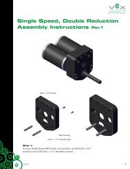
The example above has two rotating joints. It has a shoulder joint and a wrist joint (you often namejoints on a robot arm similarly to their position on a human arm). These joints are commonlyconstructed by “locking” part of the robot structure onto part of a motion system. In this case, theshoulder joint has an arm locked to the gears of the shoulder gearbox; as the gears turn, the arm turnsas well. Similarly, the claw is locked to the gears of the gearbox attached to the arm.Notice that the shoulder joint has a much higher gear reduction than the wrist joint. Why is this? It isbecause of loading. The shoulder joint needs to lift the weight of the arm, the wrist joint, the claw, andwhatever object the claw has picked up. The wrist joint only needs to lift the weight of the claw andthe object it has grabbed. (The shoulder joint also has a longer lever arm to lift this load with.) Eachjoint is designed for the loads it sees.Parallel ReductionsAn example of a double-reduction joint is seen below.This joint has a gear reduction of 12:36 in the first stage, then 12:60 in the second stage. The secondstage is attached directly to the robot arm. Notice that the second stage has two gear reductions inparallel. This means that the load is divided evenly over these two reductions. By reducing the load onindividual components, the joint is less likely to experience failure (a broken gear and so on).A shock load is an instantaneous spike of loading on a mechanical system. Imagine that you grab thearm of the robot and push down on it as hard as you can in a jerking motion. This action would applya shock load to the arm gearbox. It is always a good idea to design robot joints robustly enough towithstand these shock loads. Running multiple gear reductions in parallel will spread shock loads andprevent damage.8■Unit 13: <strong>Rotating</strong> <strong>Joints</strong>
Also notice that the first stage of the gearbox does not use parallel reductions. This is because the loadhas already been reduced by gearing by the time it reaches this stage in the gearbox; these gears willbe under less load. Typically, the stages closest to the motor are under the least load and, therefore,do not need to be as robust as stages further into the gearbox.Joint LoadingAs learned in Unit 5: Speed, Power, Torque, and DC Motors and Unit 6: Gears, Chains, and Sprockets,to effectively use a motor, you need to adjust the load applied to it in such a way that it runs withinacceptable parameters. If the load applied to the motor is greater than (or equal to) the stall torque ofthe motor, the motor will stall and the arm will not move.If a force is applied on the end of the robot arm, it will apply a torque on the joint equal to themagnitude of the force multiplied by its distance from the joint. This applied force is partially causedby the weight of the arm itself, as well as any forces the arm encounters during operation (the weightof objects it is lifting and so on).It is sometimes a good idea to add a factor of safety to this force to ensure it can handle anyunanticipated loads. A factor of safety is also known as the margin of safety. It describes the amount ofoverage a system can handle. If your robot needs to pick up 10 lbs., you might design it to pick up12 lbs. This is a 1.2 factor of safety (10 * 1.2 = 12). This factor of safety will take care of any unexpectedloads (anything between 10 and 12 lbs.).Once you have determined the load torque, you may need to use gear reductions to decrease this loadbefore it is applied to the motor. In some cases, a motor will be able to directly drive a joint and handlea load, but this is not common. The motor outputs plenty of power, but it is designed to run with highspeed and low torque. You need to regear it to run with high torque and low speed. Applying gearingusing the methods learned in Unit 6: Gears, Chains, and Sprockets can put this load in the acceptablerange. But what do you need to reduce the load to?A good rule of thumb is to design rotating joints so that the load applied to them is no more than onehalfof the motor’s stall torque; however, this is not a hard rule. It is much better to design a motor toexperience the least load possible.Joint SpeedOften, it is important for a joint to move as quickly as possible. However, this is not always practical.Designing a joint to be too fast may make it uncontrollable without advanced software.The two approaches to choosing the gearing for a rotating joint are described here.Approach 1: Start with Load1. Determine the applied load on the joint.2. Decide the maximum load you want to be applied on the motor. (One-half Stall? Less?)3. Determine the required gearing to achieve this loading.4. Calculate how fast the joint will move with this gearing.5. Determine if this is a good speed.6. If the speed is good, great! Build it!Think Phase■9
7. If the speed is too fast, you then must:• Determine how fast you want the joint to move.• Calculate the gearing required for this speed. (This should be slower than the previouscalculated speed.)• Build it!8. If the speed is too slow, you then must:• Add additional power to the system so it can carry this load at a faster speed. (Add additionalmotors to this joint.)• Recalculate.Approach 2: Start with Speed1. Determine the speed that you want the joint to move. (90 degrees per second?)2. Calculate the gearing required to make the arm move at this speed.3. Decide the maximum load you want applied on the motor. (One-half Stall? Less?)4. Determine the maximum load that can be applied to the joint, based on this desired motorloading and the gearing determined earlier.5. Is this load less than what the arm is expected to experience (including a safety factor)?6. If this load is good, great! Build it.7. If this load is too low, are you willing to reduce the speed of the joint to accommodate this load?• If yes, then recalculate and build it!• If no, then add additional power to the system so it can carry more load at this speed (addadditional motors to the joint) and then recalculate.NOTE: Reducing the length of the arm attached to the joint will reduce the amount of torque a givenload will apply to the joint.Both of these approaches work well for designing a rotating joint. Each process requires iteration tobe successful. Sometimes, you will find yourself redoing work you have already done, in an effort tofind a design that works best for your applications.10■Unit 13: <strong>Rotating</strong> <strong>Joints</strong>
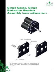
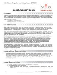
Benchmark DesignsHere are two examples of <strong>VEX</strong> gearing used in rotating joints. Both of these examples use the <strong>VEX</strong>spur gears; the <strong>VEX</strong> Chain is not recommended for high-load joints.Medium-speed/medium-load joint (single-stage reduction)Medium-Speed/Medium-Load Joint (Single-Stage Reduction)This joint uses two 12:84 gear reductions in parallel, as shown in the image. This joint spins at amedium speed and is good for picking up medium-sized loads. It can be used well as a wrist or elbowjoint in an arm. It can also be used for a shoulder joint in a low-load application.It is easy to modify this joint to make it faster, but difficult to make it slower. To increase the speed ofthe joint, simply replace the 84-tooth gears with 60-tooth gears and/or replace the 12-tooth gearswith 36-tooth gears.Think Phase■11
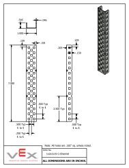
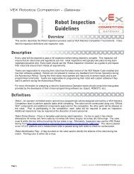
Low-speed/high-load joint (double-stage reduction)Low-Speed/High-Load Joint (Double-Stage Reduction)This joint uses a 12:60 reduction as its initial stage and two 12:60 reductions in parallel as its secondstage. This joint moves at a relatively slow speed but can lift a significant load. It works well as ashoulder joint in high-load applications.It is easy to modify this joint to make it either faster or slower. To increase the speed of the joint,replace one stage of 12-tooth gears (either the first stage 12-tooth gear or both of the second stage12-tooth gears) with 36-tooth gears. To increase it even more, make this change on both stages. Todecrease the speed of this joint, replace the 60-tooth gears in the second stage with 84-tooth gears.These are just two examples of the numerous ways to construct rotating joints. To be successful,always maintain the principles and methodology discussed in this unit.12■Unit 13: <strong>Rotating</strong> <strong>Joints</strong>
Create PhaseOverviewIn this phase, you learn about creating an assembly with 2D sketches and 3D models. The objective ofthe assembly is to analyze the motion of grippers in a parallel gripper mechanism.Phase ObjectiveAfter completing this phase, you will be able to:■Analyze the motion of a parallel gripper mechanism.Prerequisites and Related ResourcesBefore starting this phase, you must have:■■■A working knowledge of the Windows operating system.Completed Unit 1: Introduction to Vex and <strong>Robotics</strong> > Getting Started with Autodesk Inventor.Completed Unit 2: Introduction to Autodesk Inventor > Quick Start for Autodesk Inventor.Create Phase■13
Technical OverviewThe following Autodesk Inventor tools are used in this phase:Icon Name DescriptionNewTwo-Point Rectangle2D SketchPoint, Center PointPlace ComponentConstraintThe File New dialog box displays the templates for selectionwhen creating a file. Double-click an icon to select a template orclick a tab to show more templates.Used to create rectangles by specifying diagonal corners. Eachrectangle side is a line segment.Consists of the sketch plane, a coordinate system, 2D curves,and the dimensions and constraints applied to the curves.Points can be either sketch points or center points. Click theCenter Point tool on the Standard toolbar to switch the pointstyle between sketch point and center (default). In the graphicswindow, center points appear as crosshair symbols and sketchpoints appear as dots.Specifies one or more files to place as a component in anassembly.Assembly constraints determine how components in theassembly fit together. As you apply constraints, you removedegrees of freedom, thus restricting the ways components canmove.Required Supplies and SoftwareThe following software is used in this phase:SoftwareAutodesk Inventor Professional 200914■Unit 13: <strong>Rotating</strong> <strong>Joints</strong>
Exercise: Model a Parallel GripperIn this exercise, you model a parallel gripper. Theobjective is to create a layout that simulates themotion and illustrates how the faces of the grippersmove together and apart in parallel.The typical workflow in Autodesk Inventor is tocreate parts and then assemble them. In thisexercise, you minimize the modeling required byusing 2D sketches with 3D models.3. Drag edge 1 of the gripper sketch and slowlymove it backward and forward. Note themotion of the gripper.4. Repeat this for edge 2 on the other gripper.The completed exerciseOpen the FileThis workflow illustrates how you can use sketchesinstead of 3D models to solve a design problem.The design team posted the partially completeassembly so that you can finish the design.The sketches represent standard robot parts withwork points located every 0.5 inches. These pointsare the hole centers on a flat bar.1. Make IFI_Unit13.ipj the active project.2. Open Gripper_Assembly.iam.Create the LinkIn this section of the exercise, you create anotherpart and link the two gripper assemblies to show thatthe faces of the grippers stay parallel as they movetogether and apart.1. Click New.2. On the English tab, double-clickStandard (in).ipt.3. Click Two-Point Rectangle.Create Phase■15
4. Create a rectangle. Add 0.5 and 2.5dimensions as shown.10. Create a rectangle. Add 0.06125 and 2.0dimensions as shown.5. On the ViewCube, click Home.6. Press E to start the Extrude tool.■For Distance, enter 0.125.■■Click Flip to change the direction of theextrusion.Click OK.11. Press E to start the Extrude tool.■■■■For the profile, select inside the rectangle.Under Operation, click Cut.Under Extents, select All from the list.Click OK.7. Click 2D Sketch.8. Select the top face of the extrusion.Add a Slot and Hole to the LinkIn this section of the exercise, you add a slot and ahole to the link.1. Click 2D Sketch.2. Select the face as shown.9. Click Two-Point Rectangle.3. On the ViewCube, click Front.16■Unit 13: <strong>Rotating</strong> <strong>Joints</strong>
4. Create and dimension a sketch as shown. Adda horizontal constraint between the center ofthe left arc and the left vertical edge of thesketch.10. Click Point, Center Point.11. Create a center point as shown. Dimensionthe point and then center it vertically using ahorizontal constraint.5. On the ViewCube, click Home.6. Press E to start the Extrude tool.■■■■For the profile, select inside the sketch.Under Operation, click Cut.Under Distance, select All from the list.Click OK.12. On the ViewCube, click Home.13. Press H to start the Hole tool.■For Diameter, enter 0.26.■■Under Termination, select Through Allfrom the list.Click OK.7. Click 2D Sketch.8. Select the face as shown.14. Save the file as Link.ipt.15. Close the file.9. On the ViewCube, click Front.Create Phase■17
Add Links to the AssemblyIn this section of the exercise, you place two links inthe gripper assembly.1. If Gripper_Assembly is not active, make it theactive window.2. Click Place Component.8. In the browser, expand Link1:1.Click Work Plane4.9. Click Apply.3. In the Place Component dialog box, selectLink.ipt. Click Open.4. Place two link components in the assembly.Right-click in the graphics window.Click Done.10. Under Solution, click Mate.11. Select the center of the hole in the link (1).5. Click Constraint.12. Select the fifth work point on the arm (2).6. Under Solution, click Flush.7. Select the front face of the link.13. Click Apply.18■Unit 13: <strong>Rotating</strong> <strong>Joints</strong>
14. Under Type, click Angle.15. Select the edge of link (1), and the arm (2).Place the Actuator in the AssemblyIn this section of the exercise, you place the actuatorin the assembly and constrain it to the links.1. Click Place Component.2. In the Place Component dialog box, selectActuator.ipt. Click Open.3. Place one component in the assembly. Rightclickin the graphics window. Click Done.16. For Offset, enter 270. Click Apply.4. Click Constraint.17. Using a similar workflow, assemble thesecond link to Arm1:3.5. Under Solution, click Flush.Note the following:■For this link, the back face must be flushto the arm.■The offset for the angle is 90.6. Select the front face of the link.7. In the browser, expand Link1:1. ClickWork Plane4.Create Phase■19
8. Click Apply.9. Under Solution, click Mate.10. Select the edge of the work plane on theactuator and the edge of the work plane inthe center of the link. Click OK.14. Select the face of the pin on the actuator.15. Select the face of the slot on one of the links.11. Drag the actuator close to the links. Zoom into the three components.16. Click Apply.12. Click Constraint.13. Click the Transitional tab.17. Repeat this workflow for the second link.20■Unit 13: <strong>Rotating</strong> <strong>Joints</strong>
Drive the ActuatorIn this section of the exercise, you move the actuatorby driving a constraint.8. In the browser, under Link1:1, right-click thelast constraint in the list. It is the flushconstraint you created in the previous step.Click Drive Constraint.1. On the ViewCube, click Home.2. Slowly drag the actuator. The links now movein unison.3. Click Constraint.4. Under Solution, click Flush.5. Select the face of the actuator as shown.9. In the Drive Constraint dialog box:■For Start, enter 0.■For End, enter -0.375.■Click More to expand the dialog box.■For Increment, enter 0.01.■Under Repetitions, select Start/End/Start.■For Repetitions, enter 5.6. In the browser, expand Link1:1 and the Originfolder. Click XY Plane.■Click Forward or Reverse, depending onwhich is active.10. Review the motion of the parts. The opposingfaces of the grippers remain parallel as themechanism moves together and apart.11. Save the file.7. Click OK.Create Phase■21
Build PhaseOverviewIn this phase, you design an arm on a rotating joint, which will attach to the gripper you designed andbuilt in Unit 12: <strong>Rotating</strong> <strong>Joints</strong> > Build Phase. You then attach the arm to one of your previously builtdrivetrains.Phase ObjectivesAfter completing this phase, you will be able to:■■Apply the knowledge gained in the Unit 13: Object Manipulation > Think Phase to design andbuild a rotating joint.Attach different mechanisms together to create a larger subsystem.Prerequisites and Related ResourcesBefore starting this phase, you must have completed:■Unit 13: <strong>Rotating</strong> <strong>Joints</strong> > Think Phase.Related phase resources are:■■■■■■Unit 1: Introduction to <strong>VEX</strong> and <strong>Robotics</strong>.Unit 4: Microcontroller and Transmitter Overview.Unit 5: Speed, Power, Torque, and DC Motors.Unit 6: Gears, Chains, and Sprockets.Unit 7: Advanced Gears.Unit 12: Object Manipulation.Required Supplies and SoftwareThe following supplies are used in this phase:Supplies<strong>VEX</strong> Classroom Lab KitOne of the drivetrains built in Unit 9: Drivetrain Design 1 > Build Phase or Unit 10: DrivetrainDesign 2 > Build PhaseThe gripper built in the Unit 12: Object Manipulation > Build PhaseNotebook and penWork surfaceSmall storage container for loose partsOptional: Autodesk Inventor Professional 200922■Unit 13: <strong>Rotating</strong> <strong>Joints</strong>
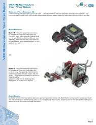
ActivityIn this activity, you design a simple, single-jointed arm. You then attach the gripper from the Unit 12:Object Manipulation > Build Phase to the arm. Finally, you mount this arm to one of your previouslybuilt drivetrains. In the Amaze Phase for this unit, you will be required to move a stack of three sodacans across the room with this robot.1. In your notebook, brainstorm the different types of arms that can be used to lift your gripperand soda can. The following image shows an example of the drive assembly for an arm.When designing your arm, you need to consider many factors, some of which include:■■■■■What type of gear reduction should be used to make sure it can lift the weight of thegripper and the can?How fast should the arm to rotate?How will the gripper attach to it?How much reach does the arm need?How/where will the arm attach to the drivetrain?Work as professionals in the engineering and design fields by leveraging the power ofAutodesk Inventor to explore potential solutions through the creation and testing of digitalprototypes.NOTE: Come to class prepared to build and test your best ideas! Team members can download afree version of Autodesk Inventor Professional to use at home by joining the Autodesk StudentEngineering and Design Community today at http://www.autodesk.com/edcommunity.Build Phase■23
2. Based on your criteria, choose a design and start building!Remember, the challenge in the upcoming Amaze Phase is to move a stack of three soda cansacross a room. You may want to modify your gripper or drivetrain so that you can completethis challenge as quickly as possible.3. Attach your gripper to your completed arm.4. Mount the entire arm to the chosen drivetrain. For ideas on how to mount the arm, go back tothe Unit 3 Build Phase and review how Protobot’s arm was mounted to its base.5. Plug in motors and servos to the appropriate ports in the Microcontroller. Test your arm witha Transmitter to make sure everything is functioning correctly.6. Move on to the Amaze Phase and get ready for your upcoming challenge!24■Unit 13: <strong>Rotating</strong> <strong>Joints</strong>
Amaze PhaseOverviewIn this phase, you use your robot from Unit 13: <strong>Rotating</strong> <strong>Joints</strong> > Build Phase to move a stack of threesoda cans across a room as quickly as possible.Phase ObjectivesAfter completing this phase, you will be able to:■■Test the designs of drivetrains, rotating joints, and grippers.Improve designs based on performance reviews.Prerequisites and Related ResourcesBefore starting this phase, you must have:■■■Completed Unit 13: <strong>Rotating</strong> <strong>Joints</strong> > Think Phase.Completed Unit 13: <strong>Rotating</strong> <strong>Joints</strong> > Build Phase.An assembled single-jointed arm from the Unit 13: <strong>Rotating</strong> <strong>Joints</strong> > Build Phase attached to thegripper created in the Unit 12: Object Manipulation > Build Phase that is attached to a drivetrainof your choice.Related phase resources are:■■■■■■Unit 1: Introduction to <strong>VEX</strong> and <strong>Robotics</strong>.Unit 4: Microcontroller and Transmitter Overview.Unit 5: Speed, Power, Torque, and DC Motors.Unit 6: Gears, Chains, and Sprockets.Unit 7: Advanced Gears.Unit 12: Object Manipulation.Amaze Phase■25
Required Supplies and SoftwareThe following supplies are used in this phase:Supplies<strong>VEX</strong> Classroom Lab KitThe robot built in the Unit 13: <strong>Rotating</strong> <strong>Joints</strong> > Build PhaseNotebook and pen8’ x 8’ of open spaceThree soda cansMasking tapeMeasuring tapeOne stopwatch26■Unit 13: <strong>Rotating</strong> <strong>Joints</strong>
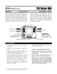
EvaluationChallengeIn this challenge, you attempt to move a stack of three soda cans across a room as quickly as possible.Instructions Figures 1 and 21. Stack three soda cans on the floor, as shownin Figure 1.2. Measure 6’ from the stack of soda cans.Using the masking tape, place an ‘X’ on thefloor. This will be your destination target forthe cans.3. Using your robot, move the three cans tothe ‘X.’ Your goal is to restock the cans onthe ‘X’ as fast as possible. See Figure 2.4. Repeat the challenge a few times to try andimprove your time. Be sure to record yourtimes in your notebook.5. While performing the challenge, payattention to which parts of your robot arefunctioning well and which parts can useimprovement.Figure 1Figure 2Amaze Phase■27
Engineering NotebookAfter seeing your robot perform in the challenge, how can you improve its performance? Whatchanges would you make in the following areas:■■■DrivetrainArmGripperIf you were to repeat the challenge and had to start from scratch, describe the type of robot you wouldbuild. If it is the same robot that you already built, explain why.Was this challenge harder or easier than you expected?PresentationPresent your robot to the class. Explain why you chose the design you did and how you wouldimprove upon it. Describe the feature of your robot that you feel is most unique.28■Unit 13: <strong>Rotating</strong> <strong>Joints</strong>
STEM ConnectionsBackgroundFixed-wing aircraft rely on rotating flaps to guide the plane. These flaps can be found both on thewings and the tail of the plane and can be observed in action if you are sitting in a seat near the wings.ScienceFixed-wing aircraft represent humans’ best attempt at flight, but the wings of a bird are far superior.1. What types of joint movement occur during the motion of a bird in flight?2. How many degrees of freedom does a bird’s wing possess?TechnologyMany believe that the future of aircraft technology is in “switchblade” plane design, a concept thatenables an aircraft to alter wing configuration in midfield to adjust its agility and speed. Some designsadjust each side wing individually, while others pivot the entire wing into a new position.■What type of joint movement might be employed to accomplish this wing readjustment, and whatkind of joint loading can you envision with this new technology?STEM Connections■29
EngineeringThis unit discussed joint loading and creating a factor of safety for your joints. What factors would youconsider when calculating the joint load of an airplane tail flap?■What do you suppose is the factor of safety for this joint and how would you calculate it?Math1. Suppose that you have the double-reduction joint as shown under Parallel Reductions, in theThink Phase in Unit 13: <strong>Rotating</strong> <strong>Joints</strong>. What is the overall gear reduction of the whole system?2. Given that the <strong>VEX</strong> motors have a stall torque of about 6.5 in-lbs., and you want to stay below 50%of that threshold if possible, try to keep the motor load under 3 in-lbs. Considering the gear ratioof the system, how much torque can the arm apply?3. How much weight can it lift at a distance of 10 inches from the joint?30■Unit 13: <strong>Rotating</strong> <strong>Joints</strong>