Download - VEX Robotics
Download - VEX Robotics
Download - VEX Robotics
- No tags were found...

You also want an ePaper? Increase the reach of your titles
YUMPU automatically turns print PDFs into web optimized ePapers that Google loves.
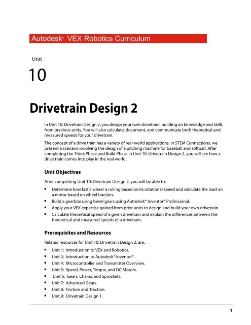
10:Unit10Drivetrain Design 2 UnitIn Unit 10: Drivetrain Design 2, you design your own drivetrain, building on knowledge and skillsfrom previous units. You will also calculate, document, and communicate both theoretical andmeasured speeds for your drivetrain.The concept of a drive train has a variety of real-world applications. In STEM Connections, wepresent a scenario involving the design of a pitching machine for baseball and softball. Aftercompleting the Think Phase and Build Phase in Unit 10: Drivetrain Design 2, you will see how adrive train comes into play in the real world.Unit ObjectivesAfter completing Unit 10: Drivetrain Design 2, you will be able to:■■■■Determine how fast a wheel is rolling based on its rotational speed and calculate the load ona motor based on wheel traction.Build a gearbox using bevel gears using Autodesk® Inventor® Professional.Apply your <strong>VEX</strong> expertise gained from prior units to design and build your own drivetrain.Calculate theoretical speed of a given drivetrain and explain the differences between thetheoretical and measured speeds of a drivetrain.Prerequisites and ResourcesRelated resources for Unit 10: Drivetrain Design 2, are:■■■■Unit 1: Introduction to <strong>VEX</strong> and <strong>Robotics</strong>.Unit 2: Introduction to Autodesk® Inventor®.Unit 4: Microcontroller and Transmitter Overview.Unit 5: Speed, Power, Torque, and DC Motors.■Unit 6: Gears, Chains, and Sprockets.■■Unit 7: Advanced Gears.Unit 8: Friction and Traction.■Unit 9: Drivetrain Design 1.1
SuppliesWork surfaceSmall storage container for loose parts4’x25’ of open floor spaceMasking tapeMeasuring tapeOne stopwatchOne calculatorSoftwareAcademic StandardsThe following national academic standards are supported in Unit 10: Drivetrain Design 2.PhaseThinkStandardScience (NSES)Unifying Concepts and Processes: Form and Function; Change, Constancy, andMeasurementPhysical Science: Motions and ForcesScience and Technology: Abilities of Technological DesignTechnology (ITEA)5.8: The Attributes of DesignMathematics (NCTM)AlgebraAnalyze change in various contexts.MeasurementUnderstand measurable attributes of objects and the units, systems, and processes ofmeasurement.Apply appropriate techniques, tools, and formulas to determine measurements.CommunicationCommunicate mathematical thinking coherently and clearly to peers, teachers,and others.ConnectionsRecognize and apply mathematics in contexts outside of mathematics.■3
PhaseCreateBuildStandardScience (NSES)Unifying Concepts and Processes: Form and FunctionPhysical Science: Motions and ForcesScience and Technology: Abilities of Technological DesignTechnology (ITEA)5.8: The Attributes of Design5.9: Engineering Design6.12: Use and Maintain Technological Products and SystemsMathematics (NCTM)Numbers and OperationsUnderstand numbers, ways of representing numbers, relationships among numbers,and number systems.Algebra StandardUnderstand patterns, relations, and functions.Geometry StandardUse visualization, spatial reasoning, and geometric modeling to solve problems.Measurement StandardUnderstand measurable attributes of objects and the units, systems, and processesof measurement.Science (NSES)Unifying Concepts and Processes: Form and Function; Change, Constancy, and MeasurementPhysical Science: Motions and ForcesScience and Technology: Abilities of Technological DesignTechnology (ITEA)5.8: The Attributes of Design5.9: Engineering Design6.11: Apply the Design ProcessMathematics (NCTM)Numbers and OperationsCompute fluently and make reasonable estimates.AlgebraAnalyze change in various contexts.GeometryUse visualization, spatial reasoning, and geometric modeling to solve problems.MeasurementUnderstand measurable attributes of objects and the units, systems, and processesof measurement.Apply appropriate techniques, tools, and formulas to determine measurements.ConnectionsRecognize and apply mathematics in contexts outside of mathematics.4■Unit 10: Drivetrain Design 2
PhaseAmazeStandardScience (NSES)Unifying Concepts and Processes: Form and Function; Change, Constancy, and MeasurementPhysical Science: Motions and ForcesScience and Technology: Abilities of Technological DesignTechnology (ITEA)5.8: The Attributes of Design5.9: Engineering Design6.11: Apply the Design ProcessMathematics (NCTM)Numbers and OperationsCompute fluently and make reasonable estimates.AlgebraAnalyze change in various contexts.GeometryUse visualization, spatial reasoning, and geometric modeling to solve problems.MeasurementUnderstand measurable attributes of objects and the units, systems, and processes ofmeasurement.Apply appropriate techniques, tools, and formulas to determine measurements.CommunicationCommunicate mathematical thinking coherently and clearly to peers, teachers,and others.ConnectionsRecognize and apply mathematics in contexts outside of mathematics.■5
Think PhaseOverviewThis phase describes how to calculate the gearing for a robot drivetrain. It focuses on two mainmethods: calculating based on output speed, and calculating based on motor load.Phase ObjectivesAfter completing this phase, you will be able to:■■Determine how fast a wheel is rolling based on its rotational speed.Calculate the load on a motor based on wheel traction.Prerequisites and ResourcesRelated phase resources are:■■■Unit 5: Speed, Power, Torque, and DC Motors.Unit 6: Gears, Chains, and Sprockets.Unit 8: Friction and Traction.■Unit 9: Drivetrain Design 1.■A basic understanding of unit analysis.Required Supplies and SoftwareThe following supplies are used in this phase.SuppliesNotebook and penWork surface6■Unit 10: Drivetrain Design 2
Research and ActivityDrivetrain DesignIn Unit 9: Drivetrain Design 1, we discussed the factors that affect what makes a Drivetrain turn. Thisunit describes the Geartrain or Powertrain of the Drivetrain. The Geartrain represents the part of theDrivetrain that transmits power from the Motor to the ground.Wheel SpeedThe first concept to understand is figuring out how fast the robot moves across the floor based on howfast the wheel is spinning. For each time the wheel makes a full revolution, it rolls forward a distanceequal to its circumference. So if we calculate the circumference of the wheel, we know exactly how farthe robot goes per revolution.The circumference of a wheel is equal to its diameter multiplied by Pi (about 3.14).Once we know the circumference of the wheel, we can calculate how fast it is rolling based on itsrotational speed. In the example below, we assume the wheel diameter is 4 inches, and the wheel isspinning at 50 RPM. Let’s calculate how fast the wheel is rolling in inches per second. First, we calculatethe circumference:After we calculate the circumference, we can determine the ground speed based on the wheel RPM.Most of the following is just unit analysis and cancellation:Now we know the way to calculate ground speed from wheel RPM. If we know the <strong>VEX</strong> Motor has anoutput of approximately 100 RPM, and we know what reduction we want our wheel to spin at, we cancalculate the approximate gear reduction needed.Think Phase■7
Let’s say we have a 5 inch diameter wheel, we want the robot to travel at about 4 feet per second, andwe know the <strong>VEX</strong> motor spins at about 100 RPM. The first step is to calculate the diameter of the wheel,and also convert our target speed to inches per second.So now we know that we need to move 48 inches in one second, and that each revolution is15.7 inches; knowing this we can calculate how many revolutions per second the wheel needs to turnto achieve 4 feet per second.Now we know that we need the wheel to spin at 183.42 revolutions per minute, and we know the <strong>VEX</strong>motor spins at 100 RPM, we can calculate the Gear Ratio needed to achieve our top speed.To achieve a speed of 4 ft/sec with a 5” wheel and a <strong>VEX</strong> motor; we need a gear reduction of .545:1. Wenow need to figure out what gears to use to achieve this gear ratio, or try to get as close as possible ifwe do not have the correct gears available. The <strong>VEX</strong> <strong>Robotics</strong> Design System has several GearingOptions available. The following chart shows all the gear reduction pairs possible using <strong>VEX</strong> SpurGears and <strong>VEX</strong> Chains and Sprockets.8■Unit 10: Drivetrain Design 2
Using the above table we can see the ratios closest to .545. From here it is a question of choosingwhich option best suits the design. In this case there is no combination which yields exactly the ratiowe want, but there are several which are close.You can see how one would follow this same process to calculate the gearing in other situationsas well.Motor Load GearingThe second concept to understand is calculating the maximum load applied to the motor by thedrivetrain. This occurs during the “wall push” situation; that is, when the robot is up against animmovable object and is running full throttle into it. In this situation the wheels should slip on thefloor, but the friction between the wheels and the floor will act as a brake on the motor.The first step is determining how many wheels are acting as a brake on the gearbox we are looking at.Only wheels directly linked through gearing or chain apply load to the gearbox.In this example, let’s consider the example of a 4WD robot where each side of the robot has 2 wheelslinked to the same gearbox. In this case 1/2 the robot weight will be resting on the wheels. This weightis the Normal Force which determines the Force of Friction applied by these two wheels on thegearbox.This torque is applied through the gearbox onto the motor or motors. If a gearbox has multiplemotors, then the torque will be divided evenly between them.It is important to design the gearing such that the load applied on each motor is not higher than themotor limit. <strong>VEX</strong> Motors cannot draw more than 1 Amp of current for an extend period of time. Usethe principles learned in Unit 5 and Unit 6 to ensure this limit is not exceeded.Think Phase■9
Drivetrain DesignThe two methods listed above are critical for drivetrain design. A good designer will not only gear arobot such that it moves at the desired speed but will also ensure that there is not excessive loadingon the motors.More Information on TransmissionsUsing different combinations of gear ratios and the principle of mechanical advantage, transmissionsprovide a torque increase and speed reduction from the high speed and low torque supplied by thedriving motor or engine.Transmissions are used in practically every industry that uses machinery. They are sometimes used instationary applications to move or lift heavy loads, but are more easily recognized and appreciated invehicles to direct power to make them move. They not only transmit power out of the engine, butmore simplistic gearboxes redirect the power out to the wheels. In addition to geared transmissions,heavy construction and agricultural equipment sometimes utilize hydrostatic and electric drives.Hydrostatic drives utilize fluids pumped through hoses to drive components instead of heavyspinning driveshafts and mechanical connections. Electric drives use direct-driven systems in whichthe motors are actually mounted at the location where the power is needed. Electricity is sent from thepower source to the motors through wires, eliminating the need for mechanical power transfer.Gearboxes are the simplest form of a transmission. Transmissions do just what their name implies:they transmit torque and speed. Gearboxes are different from the multi-speed or shiftabletransmissions most people think of when they hear the term, because their gear ratio is fixed when itis assembled. A gearbox is incapable of shifting, which means that its gear ratio cannot be changedwhile it is operating.Gearboxes are found in a wide variety of different applications. They were first used in windmills, grainmills, and steam engines. They sometimes supported a 90-degree change in the direction of rotationand occasionally had multiple output shafts to run several different machines at the same time. Theywere particularly desirable in operations where a large speed reduction and torque increase wereneeded in lifting loads and pumping liquids. You could say that gearboxes were perfected down onthe farm.Low gear ratios provide lots of torque with little speed, while higher gear ratios provide speed withlittle torque.10■Unit 10: Drivetrain Design 2
Create PhaseOverviewIn this phase, you learn about creating a gearbox with bevel gears. You use the Bevel Gears Generatoroption of Design Accelerator.ObjectivesAfter completing this lesson, you will be able to:■■Describe options for bevel gear generation.Build a gearbox using bevel gears.Prerequisites and ResourcesBefore starting this phase, you must have:■■■A working knowledge of the Windows operating system.Completed Unit 1: Introduction to <strong>VEX</strong> and <strong>Robotics</strong> > Getting Started with Autodesk Inventor.Completed Unit 2: Introduction to Autodesk Inventor > Quick Start for Autodesk Inventor.Create Phase■11
Technical OverviewThe following Autodesk Inventor tools are used in this phase.Icon Name Description2D SketchBevel Gears GeneratorCenter Point CircleChamferCircular PatternExtrudeGeneral DimensionInsert iFeatureRibA sketch consists of the sketch plane, a coordinate system,2D curves, and the dimensions and constraints applied to thecurves.Calculates dimensions and strength check of bevel gearingwith straight and helical teeth. It contains geometriccalculations for designing different types of correctiondistributions, including a correction with compensationof slips.Creates a circle from a center point and radius, or tangent tothree lines.Chamfers bevel part edges in both the part and assemblyenvironments. Chamfers may be equal distance from the edge,a specified distance and angle from an edge, or a differentdistance from the edge for each face.Part, surface, and assembly features can be arranged in apattern to represent hole patterns or textures, slots, notches,or other symmetrical arrangements.Creates a feature by adding depth to a sketched profile.Feature shape is controlled by profile shape, extrusion extent,and taper angle. Unless the extruded feature is a base feature,its relationship to an existing feature is defined by selecting aBoolean operation (join, cut, or intersect with existing feature).Adds dimensions to a sketch. Dimensions control the size of apart. They can be expressed as numeric constants, as variablesin an equation, or in parameter files.An iFeature is one or more features that can be saved and reusedin other designs. You can create an iFeature from any sketchedfeature that you determine to be useful for other designs.Features dependent on the sketched feature are included in theiFeature. After you create an iFeature and store it in a catalog,you can place it in a part by dragging it from Windows Explorerand dropping it in the part file or by using the Insert iFeaturetool.Ribs and webs are often used in molds and castings. In plasticparts, they are commonly used to create rigidity and to preventwarping.12■Unit 10: Drivetrain Design 2
Required Supplies and SoftwareThe following software is used in this phase.SoftwareAutodesk Inventor Professional 2009Gear Generator OptionsWhen you create or edit gear sets, you use the Gears Component Generator dialog box. With theDesign Accelerator, you can design spur, bevel, and worm gear sets efficiently. To design and positionyour gear sets in your assemblies, you need to know what options are available in the dialog box andwhere they are located.The Gears Component Generator dialog box is displayed after you click the tool to generate gears.Within this dialog box, you enter the method and values required to calculate the gear set. Theinformation varies depending on the method.Create Phase■13
Bevel Gear OptionsThe following options are available for creating bevel gear sets.Enter data to design the gear set.Input power and speed requirements and review calculation results. Calculations are based onpower and speed inputs, and information from the Design tab.Specify information that applies to the entire gear set.Input data specific to the first gear.Input data specific to the second gear.Display a page containing all input data and calculations.14■Unit 10: Drivetrain Design 2
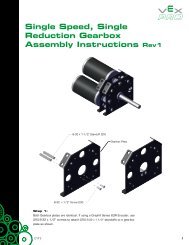
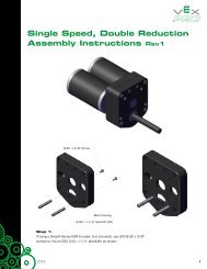
Exercise: Build a Gearbox Using Bevel GearsIn this exercise, you build a gearbox using bevelgears. You use Design Accelerator to design andcalculate the gear geometry. Bevel gears are used totransmit motion at a 90 degree angle.2. Make IFI_Unit10.ipj the active project.3. Open Bevel_Gear.iam.The completed exercise4. In the browser, select BEARING-FLAT:1. Pressand hold SHIFT. Select SHAFT-2000:2. All theparts in between are also selected.Open the FileA robot design team started designing the gear boxassembly. You inform the design team that using theBevel Gears Component Generator is therecommended workflow. This workflow illustrateshow functional design provides a quick solution to acomplex design problem.The design team posted the partially completegearbox so that you can finish the design. Thefollowing design criteria is already determined:■■The facewidth is 0.25 inches.The diametral pitch is 24 ul/in.■The number of teeth for both gears is 24.5. Right-click any of the highlighted parts. ClickVisibility to turn off the visibility of the parts.1. If a default configuration file for bevel gearconfigurations already exists for the currentuser, delete it.■■In Windows Explorer, navigate to thefollowing path: Drive:\Documents andSettings\User name\Application Data\Autodesk\Inventor 2009\DesignAccelerator\Defaults\.If the file CAGearsBevel.Imperial.xml exists,delete it.Create Phase■15
Create the Bevel GearsIn this section of the exercise, you create two bevelgears.5. Under Gear2, for Number of Teeth, enter 24.1. On the Assembly Panel, click the arrow. ClickDesign Accelerator.6. If the Summary window is not open, click thechevron.2. Click the arrow beside Spur Gears Generator.Click Bevel Gears Generator.7. Click Calculate. The current design fails.8. Click the Calculation tab.9. Under Loads:3. Under Common:■For Facewidth, enter 0.25.■For Power (P), enter 0.01.■For Speed (n), enter 100.■For Diametral Pitch, select 24.000 ul/infrom the list.10. Click Calculate. The current design iscompliant.4. Under Gear1, for Number of Teeth, enter 24.11. Click the Design tab.16■Unit 10: Drivetrain Design 2
12. Under Gear 1, click Cylindrical Face. Select theoutside face of the cylinder.15. Click OK twice.13. Under Gear 1, click Plane. Select the front faceof the cylinder.16. Drag one of the bevel gears. The second gearrotates in the opposite direction.Modify the Faces of the GearIn this section of the exercise, you modify the faces ofthe gear.1. In the browser, expand Bevel Gears:1.Right-click Bevel Gear1:1. Click Open.2. On the ViewCube, click Home.14. Repeat this workflow for Gear 2.3. Click 2D Sketch.4. Select the top face of the gear.Create Phase■17
5. Press E to start the Extrude tool.■■Select the top face of the gear.Under Operations, select Cut.■For Distance, enter 0.014.■Click the More tab.■For Taper, enter -45.■Click OK.10. On the ViewCube, click Home.6. Rotate the gear to view the bottom face asshown.Create the Shaft SupportIn this section of the exercise, you create the shaftsupport.1. Click 2D Sketch.2. Select the top face of the gear.3. Click Center Point Circle.7. Click 2D Sketch.4. Create a circle as shown. Make sure thecenter of the circle is coincident withthe center of the projected circle.8. Select the bottom face of the gear.9. Press E to start the Extrude tool.■Select the bottom face of the gear.■For Distance, enter 0.044.■Click the More tab.■For Taper, enter -45.■Click OK.5. Click General Dimension.6. Add a 0.286 dimension to the circle.18■Unit 10: Drivetrain Design 2
7. Press E to start the Extrude tool.■Select inside the circle.■For Distance, enter 0.375.■■Click Flip Direction.Click OK.8. Rotate the gear to view the extrudedfeature.Insert an iFeatureIn this section of the exercise, you insert an iFeaturefor the square hole in the gear.An iFeature is one or more features that can be savedand reused in other designs. This iFeature wasextracted from another gear.1. Click Insert iFeature.2. Click Browse. The default location foriFeatures is displayed.3. Click Workspace to navigate to yourworking folder.9. On the ViewCube, click Home.10. In the browser, expand the lastextrusion in the list. Right-click thesketch. Click Share Sketch.11. Press E to start the Extrude tool.■Select inside the circle.■For Distance, enter 0.047.■Click OK.4. Select SquareHole.ide. Click Open.5. Select the front face of the extrusion. Inthe dialog box, a check mark is added toProfile Plane1.6. Click Finish.Create Phase■19
Reduce the Weight of the GearIn this section of the exercise, you reduce the weightof the gear using a revolve cut workflow.6. Right-click in the graphics window. Click SliceGraphics.1. In the browser, expand the last extrusion.Turn off the visibility of the sketch.2. Rotate the view as shown.7. On the ViewCube, click Bottom.8. Right-click the edge of the work plane. ClickVisibility to turn off the visibility of the workplane.9. Zoom into the top half of the gear.10. Click Project Geometry.3. In the browser, expand the Origin folder.Right-click XZ Plane. Click Visibility to turnon the visibility of the plane.11. Select the two edges as shown.4. Click 2D Sketch.5. Select the edge of the work plane.12. Click Line.20■Unit 10: Drivetrain Design 2
6. Click Project Geometry.11. Right-click the vertical projected edge (1)below the new line. Click Delete.7. Select the two edges as shown.12. Rotate the part as shown.8. Click Line.9. Draw a line from 1 to 2. Make sure thatpoint 1 is coincident and point 2 is at theintersection of the projected lines. If theintersection icon is not displayed for point 2,zoom in closer.13. Click Return.14. Click Rib.15. To create the rib:■■Select the sketch line.Under Shape, select Direction.■Move the cursor below the profile. Thepreview arrow must point down. Clickwhen the arrow is pointing down.■For Thickness, enter 0.05.10. Press ESC to exit the Line tool.■Click OK.22■Unit 10: Drivetrain Design 2
16. Click Circular Pattern.17. To create the pattern:■■■■■In the graphics window, select the ribfeature.In the Circular Pattern dialog box, clickRotation Axis.Select the axis.Under Placement, for Occurrence Count,enter 4.Click OK.5. Click Done.6. In the browser, right-click Bevel Gear1. ClickiProperties.7. Click the Physical tab.8. For Material, select ABS Plastic.9. Click Apply. Note the properties of the gear,such as Mass, Area, and Volume.10. Click Close.11. Click Save.12. Close the Bevel Gear1 window. Return to theassembly.13. Turn on the visibility of all the parts. Note thatthe gear is updated in the assembly.Change the MaterialIn this section of the exercise, you change thematerial to ABS plastic.1. Click Format menu > Style and StandardEditor.2. Expand Material, and then click ABS Plastic.14. Save the file.The second gear, Bevel Gear2, is not updated.It is a separate file. In this gearbox, both gearsare identical, so you can replace Bevel Gear2,with Bevel Gear1. For the objective of theexercise, this is not required.3. For color, select Green (Flat).4. Click Save.Create Phase■23
Build PhaseOverviewIn this phase, you design and build a drivetrain of your choice.Phase ObjectivesAfter completing this phase, you will be able to:■■Apply your <strong>VEX</strong> expertise gained from prior units to design and build your own drivetrain.Build a <strong>VEX</strong> robot of your own design.PrerequisitesBefore starting this phase, you must have:■Completed Unit 10: Drivetrain Design 2 > Think Phase.Related phase resources are:■■■■■■Unit 1: Introduction to <strong>VEX</strong> and <strong>Robotics</strong>.Unit 4: Microcontroller and Transmitter Overview.Unit 5: Speed, Power, Torque, and DC Motors.Unit 6: Gears, Chains, and Sprockets.Unit 7: Advanced Gears.Unit 8: Friction and Traction.■Unit 9: Drivetrain Design 1.Required Supplies and SoftwareThe following supplies are used in this phase:Supplies<strong>VEX</strong> Classroom Lab KitNotebook and penWork surfaceSmall storage container for loose partsOptional: Autodesk Inventor Professional 200924■Unit 10: Drivetrain Design 2
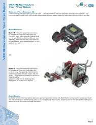
ActivityIn this activity, you design and build your own drivetrain that will be used in the challenge of theupcoming Amaze Phase. In the Amaze Phase, you will be required to calculate the theoretical speedof your drivetrain. This is something to keep in mind while designing.1. In your engineering notebook, briefly describe the drivetrain you want to build. Talk aboutfeatures such as size, number of wheels, type of wheels, and gearing.2. If you are having trouble coming up with a design, look back to some of the drivetrain designsyou saw in previous units. Do not be afraid to look to these designs for inspiration. For instance,you could take one of these designs and make your own improvements to it!Build Phase■25
3. Remember, as creative as your design may be, you are limited to the <strong>VEX</strong> parts you have in your<strong>VEX</strong> Classroom Kit.4. Look back to your previous Think Phases. The lessons learned on topics such as gearing,torque, friction, and traction will all come in handy when designing your drivetrain.5. Once you have settled on a design, sketch it out in your notebook.Work as professionals in the engineering and design fields by leveraging the power ofAutodesk Inventor to explore potential solutions through the creation and testing of digitalprototypes.NOTE: Come to class prepared to build and test your best ideas! Team members can download afree version of Autodesk Inventor Professional to use at home by joining the Autodesk StudentEngineering and Design Community today at http://www.autodesk.com/edcommunity.6. Now that you have completed a basic design, it is time to get building!7. For tips on best practices for the construction of <strong>VEX</strong> robots, refer to the previous Think andBuild Phases, as well as your Inventor’s Guide.8. Once your robot is complete, take it for a test drive, and get ready for the next phase!26■Unit 10: Drivetrain Design 2
Amaze PhaseOverviewIn this phase, you measure the speed of the drivetrain designed and built in the previousUnit 10: Drivetrain Design 2 > Build Phase. You then calculate the theoretical speed.Phase ObjectivesAfter completing this phase, you will be able to:■■Calculate theoretical speed of a given drivetrain.Explain the differences between the theoretical and measured speeds of a drivetrain.PrerequisitesBefore starting this phase, you must have:■■■Completed Unit 10: Drivetrain Design 2 > Think Phase.Completed Unit 10: Drivetrain Design 2 > Build Phase.Have an assembled drivetrain from Unit 10: Drivetrain Design 2 > Build Phase.Related phase resources are:■■■■■■Unit 1: Introduction to <strong>VEX</strong> and <strong>Robotics</strong>.Unit 4: Microcontroller and Transmitter Overview.Unit 5: Speed, Power, Torque, and DC Motors.Unit 6: Gears, Chains, and Sprockets.Unit 7: Advanced Gears.Unit 8: Friction and Traction.■Unit 9: Drivetrain Design 1.Required Supplies and SoftwareThe following supplies are used in this phase:SuppliesThe drivetrain built in the Unit 10: Drivetrain Design 2 > Build PhaseNotebook and pen4’x25’ of open floor spaceMasking tapeMeasuring tapeOne stopwatchOne calculatorAmaze Phase■27
EvaluationChallengeIn this challenge, you measure the speed of the drivetrain you built in Unit 10: DrivetrainDesign 2 > Build Phase.Instructions Figure 11. Place two strips of masking tape on the floor, 20’ apartfrom each other. (If you do not have 20’ of open space,use whatever space you have, and carefully measure thedistance between the tape lines.)2. Place your robot approximately 5’ behind one of thetape lines.3. Turn your robot and receiver on.4. Drive your robot at full speed towards the two tape lines.Start timing when the front of the robot passes the firsttape line, and stop timing when the robot passes thesecond tape line. See Figure 1.5. Record the time in your engineering notebook.6. Repeat this test 10 times.7. Calculating Average Speed: 1. Calculate the average timeof your trial. 2. Using the average time, calculate theaverage speed of your robot. Remember, the equationfor speed is: Speed = Distance / Time 3. Record thesecalculations in your notebook.Engineering NotebookUsing the equations from the Unit 10: Drivetrain 2 > Think Phase, and lessons on gearing from theUnit 6: Gears, Chains, and Sprockets > Think Phase, calculate the theoretical speed of your drivetrainin feet per second. Use 100 rpm as the free speed of a <strong>VEX</strong> motor. Be sure to show all your calculations.Remember, the free speed of a wheel is equal to the free speed of the motor, multiplied by thereduction ratio of the gearing. Be sure to convert the free speed of the wheel from revolutions perminute to revolutions per second.Now that you know how many times your wheel turns in one second, by multiplying this value by thecircumference of the wheel, you can calculate how far your robot moves in one second.Compare the values of your measured and theoretical speeds.■■Why are they different? List at least five factors that may have caused the difference.Why do you think you were asked to start the timing only after the robot had driven for a distance?PresentationPresent your findings on the differences between measured and theoretical speeds to the class.28■Unit 10: Drivetrain Design 2
STEM ConnectionsBackgroundA pitching machine works by using a spinning wheel to shoot a ball towards the plate at a given speed.The wheel’s direction of rotation is towards the batter. A ball is dropped though a tube and when itmakes contact with the surface of the spinning rubber wheel it is hurled forward. The speed of thepitch is controlled by changing the RPMs of the motor.Science1. What material should the spinning wheel be made of to grip and fling a baseball most effectively?2. Would you change this material based on the type of ball you are pitching?Technology1. You have to make a pitching machine with a motor that runs at only one speed.2. What other parts of the machine can you adjust to change the velocity of the pitch?3. How can you calculate the speed of the pitch before you put the ball in the machine?Engineering1. What scientific forces are involved in the pitching motion of the machine?2. Consider the motion of the wheel and the interaction of the wheel with the ball.STEM Connections■29
Math1. To pitch a baseball at 30 miles per hour, what do the RPMs of a 24-inch diameter wheel on apitching machine need to be?2. If a baseball player wants to hit balls that are pitched at 45 miles per hour?3. What is the RPM setting of the 24-inch wheel?4. What do the RPMs of the same wheel need to be in order to pitch balls traveling at a speed of75 miles per hour? (Reminder, 5,280 feet = 1 mile.)30■Unit 10: Drivetrain Design 2