HA-655 Series - Harmonic Drive LLC
HA-655 Series - Harmonic Drive LLC
HA-655 Series - Harmonic Drive LLC

Create successful ePaper yourself
Turn your PDF publications into a flip-book with our unique Google optimized e-Paper software.
Chapter 1Outlines of the <strong>HA</strong>-<strong>655</strong> driver<br />
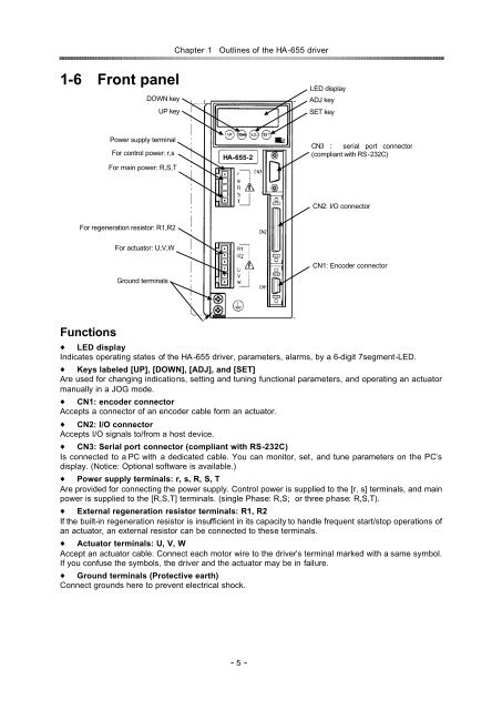
1-6Front panel<br />
DOWN key<br />
UP key<br />
LED display<br />
ADJ key<br />
SET key<br />
Power supply terminal<br />
For control power: r,s<br />
For main power: R,S,T<br />
<strong>HA</strong>-<strong>655</strong>-2<br />
CN3 serial port connector<br />
(compliant with RS-232C)<br />
CN2: I/O connector<br />
For regeneration resistor: R1,R2<br />
For actuator: U,V,W<br />
Ground terminals<br />
CN1: Encoder connector<br />
Functions<br />
LED display<br />
Indicates operating states of the <strong>HA</strong>-<strong>655</strong> driver, parameters, alarms, by a 6-digit 7segment-LED.<br />
Keys labeled [UP], [DOWN], [ADJ], and [SET]<br />
Are used for changing indications, setting and tuning functional parameters, and operating an actuator<br />
manually in a JOG mode.<br />
CN1: encoder connector<br />
Accepts a connector of an encoder cable form an actuator.<br />
CN2: I/O connector<br />
Accepts I/O signals to/from a host device.<br />
CN3: Serial port connector (compliant with RS-232C)<br />
Is connected to a PC with a dedicated cable. You can monitor, set, and tune parameters on the PC’s<br />
display. (Notice: Optional software is available.)<br />
Power supply terminals: r, s, R, S, T<br />
Are provided for connecting the power supply. Control power is supplied to the [r, s] terminals, and main<br />
power is supplied to the [R,S,T] terminals. (single Phase: R,S; or three phase: R,S,T).<br />
External regeneration resistor terminals: R1, R2<br />
If the built-in regeneration resistor is insufficient in its capacity to handle frequent start/stop operations of<br />
an actuator, an external resistor can be connected to these terminals.<br />
Actuator terminals: U, V, W<br />
Accept an actuator cable. Connect each motor wire to the driver’s terminal marked with a same symbol.<br />
If you confuse the symbols, the driver and the actuator may be in failure.<br />
Ground terminals (Protective earth)<br />
Connect grounds here to prevent electrical shock.<br />
- 5 -