ENGINE SHOP REBUILD & SERVICE PARTS MANUAL - Jacobsen
ENGINE SHOP REBUILD & SERVICE PARTS MANUAL - Jacobsen
ENGINE SHOP REBUILD & SERVICE PARTS MANUAL - Jacobsen

Create successful ePaper yourself
Turn your PDF publications into a flip-book with our unique Google optimized e-Paper software.
19<br />
13<br />
17<br />
9<br />
11<br />
16<br />
15<br />
7<br />
18<br />
3<br />
4<br />
6<br />
5<br />
8<br />
1 - INCLUDES ITEMS 3 - 16<br />
10<br />
27615-G01-rev.B<br />
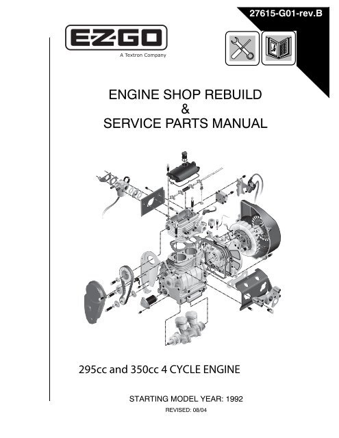
<strong>ENGINE</strong> <strong>SHOP</strong> <strong>REBUILD</strong><br />
&<br />
<strong>SERVICE</strong> <strong>PARTS</strong> <strong>MANUAL</strong><br />
295cc and 350cc 4 CYCLE <strong>ENGINE</strong><br />
STARTING MODEL YEAR: 1992<br />
REVISED: 08/04
<strong>ENGINE</strong> <strong>SHOP</strong> <strong>REBUILD</strong> &<br />
<strong>SERVICE</strong> <strong>PARTS</strong> <strong>MANUAL</strong><br />
295cc and 350cc <strong>ENGINE</strong><br />
E-Z-GO Division of Textron, Inc. reserves the right to make design changes without obligation to make these changes on units previously sold and the information<br />
contained in this manual is subject to change without notice.<br />
E-Z-GO Division of Textron, Inc. is not liable for errors in this manual or for incidental or consequential damages that result from the use of the material in this<br />
manual.<br />
CUSTOMER <strong>SERVICE</strong> DEPARTMENT IN USA PHONE: 1-800-241-5855 FAX: 1-800-448-8124<br />
OUTSIDE USA PHONE: 010-1-706-798-4311, FAX: 010-1-706-771-4609<br />
E-Z-GO DIVISION OF TEXTRON, INC., 1451 MARVIN GRIFFIN RD., AUGUSTA, GEORGIA USA 30906<br />
Engine Shop Rebuild and Parts Manual<br />
Page i
NOTES<br />
TO OBTAIN A COPY OF THE LIMITED WARRANTY THAT IS APPLICABLE TO THE VEHICLE,<br />
CALL OR WRITE THE LOCAL DISTRUBUTOR, E-Z-G0 BRANCH OR E-Z-G0 WARRANTY<br />
DEPARTMENT WITH VEHICLE SERIAL NUMBER AND MANUFACTURER’S CODE.<br />
THE USE OF NON E-Z-GO <strong>PARTS</strong> AND HARDWARE MAY VOID THE WARRANTY.<br />
TAMPERING WITH OR ADJUSTING GOVERNOR TO PERMIT VECLE TO OPERATE AT<br />
ABOVE FACTORY SETTINGS WILL VOID THE VEHICLE WARRANTY.<br />
IF APPLICABLE, REFER TO BACK COVER FOR CALIFORNIA AND/OR FEDERAL EMISSIONS<br />
CONTROL WARRANTY STATEMENT.<br />
! !<br />
Engine exhaust from this product contains chemicals known, in certain quantities, to<br />
cause cancer, birth defects, or other reproductive harm.<br />
The exhaust emissions of this vehicle’s engine complies with regulations set forth by the Environmental Protection<br />
Agency (EPA) of the United States of America (USA) at time of manufacture. Significant fines could result from modifications<br />
or tampering with the engine, fuel, ignition or air intake systems.<br />
Page ii<br />
Transaxle Shop Rebuild and Parts Manual
TABLE OF CONTENTS<br />
Section<br />
Page No.<br />
How to use the E-Z-GO Service Manual.............. ............................................. .......................................... vii<br />
Federal and California Emissions Warranty Statements.................................... ....................................Section G<br />
<strong>ENGINE</strong> DISASSEMBLY<br />
A<br />
CYLINDER HEAD REMOVAL<br />
• Air Cleaner........................................... ............................................. ......................................... A-1<br />
• Carburetor............................................ ............................................. ......................................... A-1<br />
• Coil and Bracket .................................. ............................................. ......................................... A-1<br />
• Blower Housing.................................... ............................................. ......................................... A-1<br />
• Exhaust Manifold ................................. ............................................. ......................................... A-1<br />
• Rear Cylinder Baffle............................. ............................................. ......................................... A-1<br />
• Front Timing Belt Cover ....................... ............................................. ......................................... A-1<br />
• Idler, Timing Belt and Cam Gear.......... ............................................. ......................................... A-1<br />
• Rear Timing Belt Cover........................ ............................................. ......................................... A-2<br />
• Front Cylinder Baffle ............................ ............................................. ......................................... A-2<br />
• Rocker Cover and Gasket ................... ............................................. ......................................... A-2<br />
• Rocker Assembly and Cam Shaft........ ............................................. ......................................... A-2<br />
• Cylinder Head and Gasket................... ............................................. ......................................... A-2<br />
• Valves .................................................. ............................................. ......................................... A-3<br />
• Valve Guides........................................ ............................................. ......................................... A-3<br />
<strong>ENGINE</strong> DISASSEMBLY<br />
B<br />
CRANKCASE DISASSEMBLY<br />
• Oil Filter ............................................... ............................................. ......................................... B-1<br />
• Fan Hub ............................................... ............................................. ......................................... B-1<br />
• Pulser Coil ........................................... ............................................. ......................................... B-1<br />
• Oil Pressure Switch ............................. ............................................. ......................................... B-1<br />
• Oil Pump .............................................. ............................................. ......................................... B-1<br />
• Crankcase End Cover.......................... ............................................. ......................................... B-2<br />
• End Cover Gasket and Oil Feed O-Ring ........................................... ......................................... B-2<br />
• Balancer Shaft ..................................... ............................................. ......................................... B-2<br />
• Pistons ................................................. ............................................. ......................................... B-2<br />
• Crankshaft............................................ ............................................. ......................................... B-2<br />
• Balancer and Crankshaft Seals ........... ............................................. ......................................... B-2<br />
• Balancer Shaft and Crankcase Bearings........................................... ......................................... B-2<br />
• PCV Valve............................................ ............................................. ......................................... B-3<br />
• Crankcase End Cover.......................... ............................................. ......................................... B-3<br />
• Piston and Connecting Rod ................. ............................................. ......................................... B-3<br />
• Crankshaft Bearing .............................. ............................................. ......................................... B-3<br />
Engine Shop Rebuild and Parts Manual<br />
Page iii
TABLE OF CONTENTS<br />
Section<br />
Page No.<br />
<strong>ENGINE</strong> MEASUREMENTS AND SPECIFICATIONS C<br />
<strong>ENGINE</strong> MEASUREMENTS AND SPECIFICATIONS<br />
• Check Flatness of Crankcase, End Cover and Cylinder Head .......... .........................................C-1<br />
• Crankcase Cylinder Bores ................... ............................................. .........................................C-2<br />
• Crankcase and End Cover Crankshaft Bearing Bores ...................... .........................................C-2<br />
• Crankshaft Journals and Gear............. ............................................. .........................................C-2<br />
• Crankcase and End Cover Balancer Shaft Bearing Bores ................ .........................................C-2<br />
• Balancer Shaft Journals and Gear....... ............................................. .........................................C-2<br />
• Piston................................................... ............................................. .........................................C-2<br />
• Wrist Pin .............................................. ............................................. .........................................C-3<br />
• Connecting Rod................................... ............................................. .........................................C-3<br />
• Cylinder Head Cam and Rocker Shaft Bores .................................... .........................................C-3<br />
• Valves Guides and Seats..................... ............................................. .........................................C-3<br />
• Valves and Valve Springs .................... ............................................. .........................................C-3<br />
• Camshaft ............................................. ............................................. .........................................C-3<br />
• Rocker Shaft and Rocker Arms ........... ............................................. .........................................C-3<br />
• Piston Ring Gap................................... ............................................. .........................................C-3<br />
• Torque Specifications........................... ............................................. .........................................C-3<br />
<strong>ENGINE</strong> REASSEMBLY<br />
D<br />
CRANKCASE ASSEMBLY<br />
• Honing the Cylinder Bores................... ............................................. .........................................D-1<br />
• Pistons and Connecting Rods ............. ............................................. .........................................D-1<br />
• Piston Rings......................................... ............................................. .........................................D-2<br />
• Crankcase End Cover.......................... ............................................. .........................................D-2<br />
• Crankcase Bearings ............................ ............................................. .........................................D-2<br />
• Crankshaft Bearing .............................. ............................................. .........................................D-3<br />
• Crankshaft and Balancer Shaft Seals.. ............................................. .........................................D-3<br />
• Crankshaft ........................................... ............................................. .........................................D-3<br />
• Pistons ................................................. ............................................. .........................................D-3<br />
• Balancer Shaft ..................................... ............................................. .........................................D-3<br />
• Checking Crankshaft and Balancer Shaft Endplay............................ .........................................D-4<br />
• End-Play Spacers ................................ ............................................. .........................................D-4<br />
• Oil Feed O-Ring................................... ............................................. .........................................D-4<br />
• Crankcase End Cover Gasket ............. ............................................. .........................................D-4<br />
• Crankcase End Cover.......................... ............................................. .........................................D-4<br />
• Oil Pump Gear Rotors ......................... ............................................. .........................................D-5<br />
Page iv<br />
Engine Shop Rebuild and Parts Manual
TABLE OF CONTENTS<br />
Section<br />
Page No.<br />
• Oil Pressure Switch ............................. ............................................. .........................................D-4<br />
• Pulser Coil ........................................... ............................................. .........................................D-4<br />
• Fan Hub ............................................... ............................................. .........................................D-4<br />
• Pulser Coil and Air Gap ....................... ............................................. .........................................D-5<br />
• PCV Valve............................................ ............................................. .........................................D-5<br />
• Oil Filter ............................................... ............................................. .........................................D-5<br />
<strong>ENGINE</strong> REASSEMBLY<br />
E<br />
CYLINDER HEAD ASSEMBLY<br />
• Valve Guides........................................ ............................................. ......................................... E-1<br />
• Cutting the Valve Seats........................ ............................................. ......................................... E-1<br />
• Lapping the Valves............................... ............................................. ......................................... E-1<br />
• Valve Stem Seals................................. ............................................. ......................................... E-2<br />
• Valves .................................................. ............................................. ......................................... E-2<br />
• Cylinder Head ...................................... ............................................. ......................................... E-2<br />
• Camshaft.............................................. ............................................. ......................................... E-2<br />
• Rocker Assembly................................. ............................................. ......................................... E-2<br />
• Rear Timing Belt Cover........................ ............................................. ......................................... E-3<br />
• Drive and Cam Pulleys, Idler and Timing Belt ................................... ......................................... E-3<br />
• Front Timing Belt Cover ....................... ............................................. ......................................... E-4<br />
• Front Cylinder Baffle ............................ ............................................. ......................................... E-4<br />
• Rear Cylinder Baffle............................. ............................................. ......................................... E-4<br />
• Exhaust Manifold and Gasket.............. ............................................. ......................................... E-4<br />
• Blower Housing.................................... ............................................. ......................................... E-4<br />
• Coil and Mounting Bracket................... ............................................. ......................................... E-4<br />
• Valve Adjustment ................................. ............................................. ......................................... E-4<br />
• Spark Plugs.......................................... ............................................. ......................................... E-4<br />
• Rocker Cover....................................... ............................................. ......................................... E-5<br />
• Carburetor............................................ ............................................. ......................................... E-5<br />
ILLUSTRATED <strong>PARTS</strong> BREAKDOWN<br />
F<br />
ILLUSTRATED <strong>PARTS</strong> BREAKDOWN<br />
• Engine Illustrations .............................. ............................................. ......................................... F-1<br />
• Engine Parts List.................................. ............................................. ......................................... F-6<br />
<strong>SERVICE</strong> TOOLS<br />
• CYLINDER HEAD REMOVAL ............. ............................................. ......................................... A-1<br />
• CRANKCASE DISASSEMBLY ............ ............................................. ......................................... B-1<br />
• <strong>ENGINE</strong> MEASUREMENTS AND SPECIFICATIONS ...................... .........................................C-1<br />
• CRANKCASE ASSEMBLY .................. ............................................. .........................................D-1<br />
• CYLINDER HEAD ASSEMBLY............ ............................................. ......................................... E-1<br />
Engine Shop Rebuild and Parts Manual<br />
Page v
TABLE OF CONTENTS<br />
Notes:<br />
Page vi<br />
Engine Shop Rebuild and Parts Manual
HOW TO USE THIS <strong>MANUAL</strong><br />
This manual is designed to suit the needs of mechanics at all levels of experience with the E-Z-GO 4-cycle engine. The<br />
outline format will allow the mechanic to choose the level of instructional detail needed to completely disassemble, diagnose,<br />
repair/overhaul and reassemble the engine.<br />
The manual is divided into four major operational sections, which are each divided into smaller operational sections. At<br />
the beginning of each major section is a list of tools that will be required to perform the operations desired in that section.<br />
Do not use non-specified tools (vise grips®, hammers, adjustable wrenches etc.). The use of these tools<br />
could cause permanent damage to the engine components.<br />
WE STRONGLY RECOMMEND that no matter what your experience level, you use this manual as a guide when disassembling,<br />
repairing/overhauling and reassembling the engine. Before working on the engine, read and understand the<br />
text and in particular each NOTE, CAUTION and WARNING.<br />
Some illustrations may show components that differ from your engine. This is the result of ongoing improvements to the<br />
engine design.<br />
Engine Shop Rebuild and Parts Manual<br />
vii
HOW TO USE THIS <strong>MANUAL</strong><br />
viii<br />
Engine Shop Rebuild and Parts Manual
<strong>ENGINE</strong> DISASSEMBLY<br />
TABLE OF CONTENTS FOR SECTION ‘A’<br />
SECTION TITLE<br />
A<br />
PAGE NO.<br />
CYLINDER HEAD REMOVAL..........................................................................................................A - 1<br />
Remove the Air Cleaner ........................................................................................................A - 1<br />
Remove the Carburetor.........................................................................................................A - 1<br />
Remove the Coil Mounting Bracket and Coil.........................................................................A - 1<br />
Remove the Blower Housing .................................................................................................A - 1<br />
Remove the Exhaust Manifold...............................................................................................A - 1<br />
Remove the Rear Cylinder Baffle..........................................................................................A - 1<br />
Remove the Timing Belt Cover..............................................................................................A - 1<br />
Remove the Idler, Timing Belt, Drive and Cam Pulleys.........................................................A - 1<br />
Remove the Rear Timing Belt Cover.....................................................................................A - 2<br />
Remove the Front Cylinder Baffle .........................................................................................A - 2<br />
Remove the Valve Cover and Gasket ...................................................................................A - 2<br />
Remove the Rocker Assembly and Camshaft.......................................................................A - 2<br />
Remove the Cylinder Head and Gasket from the Crankcase................................................A - 2<br />
VALVE REMOVAL ...........................................................................................................................A - 3<br />
Remove the Valves from the Cylinder Head .........................................................................A - 3<br />
Valve Guide Removal............................................................................................................A - 3<br />
LIST OF ILLUSTRATIONS<br />
Fig. A-1 Engine................................................................................................................................A - 4<br />
Fig. A-2 Cylinder Head Components...............................................................................................A - 5<br />
Fig. A-3 Valves................................................................................................................................A - 6<br />
Repair and Service Manual<br />
Page A-i
<strong>ENGINE</strong> DISASSEMBLY<br />
Notes:<br />
Page A-ii<br />
Repair and Service Manual
<strong>ENGINE</strong> DISASSEMBLY<br />
CYLINDER HEAD REMOVAL<br />
Tool List<br />
Qty. Required<br />
Extension, 3/8” drive, 4" .............................................. 1<br />
Mallet, medium wood or rubber .................................. 1<br />
Puller, seal .................................................................. 1<br />
Ratchet, 3/8” drive....................................................... 1<br />
Screwdriver, small flat blade ....................................... 1<br />
Screwdriver, medium flat blade................................... 1<br />
Socket, 8 mm, 3/8” drive ............................................. 1<br />
Socket, 10 mm, 3/8” drive ........................................... 1<br />
Socket, 12 mm, 3/8” drive ........................................... 1<br />
Socket, 13/16” spark plug, 3/8” drive .......................... 1<br />
Keep your work area clean and well organized<br />
while performing the operations described in<br />
this manual. This will help prevent accidents and reduce the<br />
possibility of mistakes that could damage or impair the performance<br />
of the engine.<br />
Crankshaft and balancer shaft bearings should<br />
be cleaned and inspected; and removed only if<br />
they appear to be damaged or excessively worn. Remove bearings<br />
that are pitted, nicked, burred, discolored or that rotate<br />
roughly or noisily.<br />
Because some mating parts with wear<br />
surfaces were machined together when<br />
the engine was manufactured, or have established wear patters<br />
during operation, the reassembly of engine parts in their original<br />
positions and orientations, with their original mating parts, is<br />
critical to the performance and life expectancy of the engine.<br />
Mark and sort all parts as they are disassembled so that they will<br />
be reassembled and installed in their original positions.<br />
Remove the Air Cleaner<br />
A variety of air cleaner configurations exist. Refer to the<br />
Technician’s Repair and Service Manual for removal/<br />
installation instructions that are appropriate to the model<br />
and year of your vehicle.<br />
Remove the Carburetor<br />
(See Fig. A-1 “Engine” on page A-4)<br />
A. Remove the choke cable bracket plate (ITEM 12).<br />
(DETAIL A)<br />
B. Slide the carburetor (ITEM 11) off of its mounting<br />
studs.<br />
C. Remove the plastic carburetor insulator (ITEM 13).<br />
A<br />
Remove the Coil Mounting Bracket and Coil<br />
(See Fig. A-1 “Engine” on page A-4)<br />
A. Remove the spark plug wires (ITEM 1) from the<br />
plugs.<br />
B. Using a spark plug wrench, remove the spark plugs<br />
(ITEM 2).<br />
C. Using a 10mm socket, remove the nut (ITEM 3) and<br />
the bolt (ITEM 4) attaching the coil bracket (ITEM 5)<br />
to the engine.<br />
Remove the Blower Housing<br />
(See Fig. A-1 “Engine” on page A-4)<br />
A. Using a 10mm socket, remove the three (3) remaining<br />
bolts (ITEM 7) and remove the blower housing<br />
(ITEM 6) from the engine.<br />
Remove the Exhaust Manifold<br />
(See Fig. A-1 “Engine” on page A-4)<br />
(Later models have exhaust mainfold as part of the head)<br />
A. Using a 12mm socket, remove the four (4) bolts<br />
(ITEM 9) or nuts that attach the exhaust manifold<br />
(ITEM 8) and gasket (ITEM 10) to the cylinder head.<br />
Remove the Rear Cylinder Baffle<br />
(See Fig. A-1 “Engine” on page A-4)<br />
A. Using a 10mm socket, remove the four (4) bolts<br />
(ITEM 12) that attach the baffle (ITEM 11) to the<br />
engine. Lift the baffle from the engine.<br />
Remove the Timing Belt Cover<br />
(See Fig. A-1 “Engine” on page A-4)<br />
A. Using a 10mm socket, remove the three (3) bolts<br />
(ITEM 14) that attach the timing belt cover (ITEM 13)<br />
to the engine.<br />
Remove the Idler, Timing Belt, Drive and<br />
Cam Pulleys<br />
(See Fig. A-1 “Engine” on page A-4)<br />
Do not twist, crimp or turn the belt<br />
inside out. This will cause the belt to<br />
fail.<br />
A. Using a 12mm socket, loosen the idler and cam pulley<br />
retaining bolts (ITEMS 15 AND 16).<br />
B. Using a 10mm socket, loosen the drive pulley retaining<br />
bolt (ITEM 17).<br />
C. Remove the idler retaining bolt (ITEM 15), idler (ITEM<br />
18), and idler spring (ITEM 19).<br />
Engine Shop Rebuild and Parts Manual<br />
Page A-1
<strong>ENGINE</strong> DISASSEMBLY<br />
D. Remove the timing belt (ITEM 20). Do not twist the<br />
belt or turn it inside out.<br />
E. Remove the drive pulley retaining bolt (ITEM 17),<br />
front belt retainer (ITEM 21), drive pulley (ITEM 22).<br />
Rear belt retainer (ITEM 23) was present on early<br />
production engines.<br />
F. Remove the cam pulley retaining bolt (ITEM 16) and<br />
the cam pulley (ITEM 24).<br />
1. Remove the pulley alignment key. Using a non-ferrous<br />
(non-steel) punch, drive the back end of the<br />
key down into the keyway, which will push the<br />
front end up.<br />
2. With the punch, gently drive the upraised key out<br />
of the keyway.<br />
Remove the Rear Timing Belt Cover<br />
(See Fig. A-1 “Engine” on page A-4)<br />
A. Using a 10mm socket, remove the two (2) bolts<br />
(ITEM 26) that attach the rear timing belt cover (ITEM<br />
25) to the engine.<br />
Remove the Front Cylinder Baffle<br />
(See Fig. A-1 “Engine” on page A-4)<br />
A. Using a 10mm socket, remove the two (2) bolts<br />
(ITEM 28) that attach the baffle (ITEM 27) to the<br />
engine.<br />
Remove the Valve Cover and Gasket<br />
(See Fig. A-2 “Cylinder Head Components” on page A-5)<br />
A. Using a 10mm socket, remove the six (6) bolts (ITEM<br />
3) that attach the rocker cover (ITEM 1) to the cylinder<br />
head. Remove the rocker cover and gasket<br />
(ITEM 2).<br />
Remove the Rocker Assembly and Camshaft<br />
(See Fig. A-2 “Cylinder Head Components” on page A-5)<br />
The rocker shafts in some early engines were<br />
manufactured with a threaded hole in the end,<br />
into which a blot is placed in order to pull the shaft from the cylinder<br />
head.<br />
Do not allow the camshaft lobes or<br />
bearing surfaces to scrape against the<br />
cylinder head. Because these parts have established wear patterns<br />
during operation, mark and sort them as they are disassembled<br />
so that they will be reassembled in their original<br />
positions.<br />
A. Remove the camshaft cover (ITEM 4).<br />
1. Using a 10mm socket, remove the three (3) bolts<br />
(ITEM 5) and one (1) stud (ITEM 6).<br />
(Later models have four (4) bolts and no stud)<br />
2. Using a rubber or wooden mallet, gently tap loose<br />
the protruding edge of the camshaft cover and pull<br />
it away from the engine.<br />
B. Using a 10mm socket, loosen the four (4) rocker arm<br />
nuts (ITEM 7).<br />
C. With a medium flat blade screwdriver, turn the four (4)<br />
rocker adjustment screws (ITEM 8) counterclockwise<br />
until they no longer exert any force on the camshaft<br />
(ITEM 9) and it can rotate freely.<br />
D. Remove the rocker assembly.<br />
1. Insert a small flat blade screwdriver into the<br />
groove in the center of the rocker shaft (ITEM 10)<br />
and push the shaft toward the fan side of the<br />
engine. Tap lightly if required.<br />
2. As the end of the rocker shaft slides out of the cylinder<br />
head, remove the four (4) rocker arms (ITEM<br />
11), two (2) spacers (ITEM 12), and one (1) spring<br />
(ITEM 13) from the other end of the shaft. Mark or<br />
sort parts as they are disassembled. Wear<br />
parts must be reassembled in their original<br />
positions.<br />
E. Carefully pull the camshaft out through the fan side of<br />
the cylinder head. Do not allow the wear surfaces of<br />
the camshaft to scrape against the cylinder head, or<br />
any part of the camshaft to scrape against the cylinder<br />
head bearing surfaces.<br />
Remove the Cylinder Head and Gasket from<br />
the Crankcase<br />
(See Fig. A-2 “Cylinder Head Components” on page A-5)<br />
Because this is an aluminum cylinder<br />
head, it is important that the clamping<br />
pressure of the mounting bolts be released evenly. Remove<br />
them in the order shown in detail A (Ref Fig. A-2 on page A-5) by<br />
loosening only 1/8 turn at a time.<br />
A. Using a 12mm socket and extension, remove six (6)<br />
cylinder head bolts (ITEM 16) in the sequence<br />
shown. Remove the cylinder head (ITEM 14), gasket<br />
(ITEM 15) and dowel pins (ITEM 19) from crankcase.<br />
Page A-2<br />
Engine Shop Rebuild and Parts Manual
<strong>ENGINE</strong> DISASSEMBLY<br />
VALVE REMOVAL<br />
Remove the Valves from the Cylinder Head<br />
(See Fig. A-3 “Valves” on page A-6)<br />
A. While supporting the valve (ITEM 1) from the bottom<br />
to prevent its downward motion, push the valve<br />
spring retainer (ITEM 2) down so that the valve stem<br />
keys (ITEM 6) are released from the retainer. It may<br />
be necessary to remove valve stem keys using a pair<br />
of needle nose pliers. (DETAIL A)<br />
B. Remove the spring retainer and spring (ITEM 3).<br />
Then push the valve down and remove it from the<br />
bottom of the cylinder head.<br />
C. Repeat steps A and B to remove the remaining<br />
valves.<br />
D. Use a small flat blade screwdriver to GENTLY pry the<br />
valve stem seals (ITEM 4) free. Remove them from<br />
the valve guides. (DETAIL B)<br />
Valve Guide Removal<br />
A. If the valve guides (ITEM 5) are to be replaced, a<br />
hydraulic press with an appropriate adaptor must be<br />
used to remove them from cylinder head.<br />
Engine Shop Rebuild and Parts Manual<br />
Page A-3
14<br />
13<br />
18<br />
15<br />
16<br />
17<br />
20<br />
21<br />
19<br />
22<br />
25<br />
27<br />
28<br />
5<br />
1<br />
10<br />
6<br />
8<br />
9<br />
4<br />
12<br />
11<br />
7<br />
<strong>ENGINE</strong> DISASSEMBLY<br />
24 26<br />
A<br />
12<br />
Newer Model<br />
11<br />
13<br />
Newer Model<br />
Newer Model<br />
3<br />
2<br />
Fig. A-1 Engine<br />
Page A-4<br />
Engine Shop Rebuild and Parts Manual
<strong>ENGINE</strong> DISASSEMBLY<br />
7<br />
13<br />
14<br />
Crankcase<br />
3<br />
1<br />
2<br />
11<br />
12<br />
15<br />
8<br />
16<br />
9<br />
19<br />
10<br />
6<br />
Groove<br />
5<br />
4<br />
A<br />
5<br />
3<br />
6 7<br />
1<br />
2<br />
4<br />
Follow numbers to remove cylinder<br />
head bolts in correct sequence<br />
Fig. A-2 Cylinder Head Components<br />
Engine Shop Rebuild and Parts Manual<br />
Page A-5
<strong>ENGINE</strong> DISASSEMBLY<br />
A<br />
2<br />
6<br />
3<br />
Push spring retainer down<br />
to release valve keys<br />
5<br />
4<br />
B<br />
Pry valve stem seal loose<br />
1<br />
Fig. A-3 Valves<br />
Page A-6<br />
Engine Shop Rebuild and Parts Manual
<strong>ENGINE</strong> DISASSEMBLY<br />
TABLE OF CONTENTS FOR SECTION ‘B’<br />
SECTION TITLE<br />
B<br />
PAGE NO.<br />
CRANKCASE DISASSEMBLY.........................................................................................................B - 1<br />
Remove the Oil Filter.............................................................................................................B - 1<br />
Remove the Fan Hub ............................................................................................................B - 1<br />
Remove the Pulser Coil.........................................................................................................B - 1<br />
Remove the Oil Pressure Switch...........................................................................................B - 1<br />
Remove the Oil Pump ...........................................................................................................B - 1<br />
Remove the Crankcase End Cover .......................................................................................B - 2<br />
Remove the Balancer Shaft...................................................................................................B - 2<br />
Remove the Pistons ..............................................................................................................B - 2<br />
Remove the Crankshaft.........................................................................................................B - 2<br />
Remove the Balancer Shaft Seal and the Crankshaft Seal...................................................B - 2<br />
Inspect the Balancer Shaft Bearing and Crankshaft Bearing ................................................B - 2<br />
Remove the PCV Valve.........................................................................................................B - 3<br />
Disassemble the Crankcase End Cover................................................................................B - 3<br />
Remove the Piston From Connecting Rod ............................................................................B - 3<br />
Removal of Crankshaft Bearing.............................................................................................B - 3<br />
LIST OF ILLUSTRATIONS<br />
Fig. B-1 Engine Components ..........................................................................................................B - 4<br />
Fig. B-2 Engine Components con’t..................................................................................................B - 5<br />
Fig. B-3 Crankshaft .........................................................................................................................B - 6<br />
Fig. B-4 Balancer Shaft Bearing, Crankshaft Bearing and PCV Valve............................................B - 7<br />
Fig. B-5 Crankcase End Cover and Crankshaft Bearing.................................................................B - 8<br />
Fig. B-6 Piston.................................................................................................................................B - 9<br />
Repair and Service Manual<br />
Page B-i
<strong>ENGINE</strong> DISASSEMBLY<br />
Notes:<br />
Page B-ii<br />
Repair and Service Manual
<strong>ENGINE</strong> DISASSEMBLY<br />
CRANKCASE DISASSEMBLY<br />
Tool List<br />
Qty. Required<br />
Extension, 3/8” drive, 4" .............................................. 1<br />
Extension, 3/8” drive, 6" .............................................. 1<br />
Mallet, medium wood or rubber .................................. 1<br />
Puller, (E-Z-GO P/N 27111-G01)................................. 1<br />
Puller, seal .................................................................. 1<br />
Punch, non-ferrous ..................................................... 1<br />
Ratchet, 3/8” drive....................................................... 1<br />
Screwdriver, small flat blade ....................................... 1<br />
Screwdriver, medium flat blade................................... 1<br />
Screwdriver, #2 phillips ............................................... 1<br />
Screwdriver, #3 phillips ............................................... 1<br />
Socket, 8 mm, 3/8” drive ............................................. 1<br />
Socket, 10 mm, 3/8” drive ........................................... 1<br />
Socket, 12 mm, 3/8” drive ........................................... 1<br />
Socket, Impact, 26 mm, 1/2” impact drive.................. 1<br />
Socket, oil pressure switch ......................................... 1<br />
Wrench, 7 mm combination ........................................ 1<br />
Wrench, 10 mm combination ...................................... 1<br />
Wrench 12 mm combination ....................................... 1<br />
Remove the Oil Filter<br />
(See Fig. B-1 “Engine Components” on page B-4)<br />
A. Using a 10mm socket, remove the three (3) bolts<br />
(ITEM 2) securing oil filter (ITEM 1) to the crankcase.<br />
B. With a twisting motion, slowly pull the filter from the<br />
crankcase and drain oil.<br />
C. Remove the O-ring (ITEM 3).<br />
D. Inspect filter for debris that could indicate an excessive<br />
wear problem or contamination.<br />
Remove the Fan Hub<br />
(See Fig. B-1 “Engine Components” on page B-4)<br />
(See Fig. B-2 “Engine Components con’t” on page B-5)<br />
Do not exert pressure against the<br />
crankshaft or fan.<br />
A. Using and impact wrench and 30 mm (Later models<br />
26MM) impact socket, remove the fan hub nut (ITEM<br />
5)<br />
B. Using and E-Z-GO Fan Hub Puller, remove the fan<br />
hub (ITEM 4). (Later models do not require a<br />
puller)<br />
Some models of puller have a sharp point that<br />
could damage the crankshaft oil passage plug.<br />
Modify per Fig. B-2, detail A.<br />
B<br />
1. Inspect puller. The end of the threaded portion<br />
should not be pointed. Grind off 1/8” to provide a<br />
taper. If desired, a nut may be used as a spacer<br />
between the puller and crankshaft. Lubricate the<br />
tip and threads of the puller shaft (ITEM 6) and<br />
place it in the indention in the end of the crankshaft.<br />
(DETAIL A)<br />
2. Install the three (3) puller bolts (ITEM 7) through<br />
the puller collar (ITEM 8) and into the threaded<br />
holes in the fan hub. Tighten the puller bolts until<br />
each is snug against the puller collar, and the collar<br />
face is at 90° to the crankshaft axis. This will<br />
insure that the hub is pulled straight and does not<br />
bind. (DETAIL A)<br />
3. Insert a large screwdriver under the puller collar<br />
and between two of the puller bolts as shown.<br />
Insert another large screwdriver through the hole<br />
in the top of the puller shaft. (DETAIL B)<br />
4. Hold the first screwdriver against the two puller<br />
bolts while turning the second screwdriver clockwise<br />
until the fan hub breaks free from the crankshaft.<br />
Do not exert pressure against the<br />
crankshaft or fan blades.<br />
5. Remove the fan hub and puller from the crankshaft.<br />
6. Remove the puller from the fan hub.<br />
Remove the Pulser Coil<br />
(See Fig. B-1 “Engine Components” on page B-4)<br />
A. Using an 8mm socket, remove two (2) bolts (ITEM<br />
10) and the pulser coil (ITEM 9).<br />
Remove the Oil Pressure Switch<br />
(See Fig. B-1 “Engine Components” on page B-4)<br />
(Later models may or may not have an oil pressure<br />
switch)<br />
A. Use a 7mm socket to remove the bolt (ITEM 12) and<br />
the wire (ITEM 13).<br />
B. Use an automotive oil pressure switch socket to<br />
remove the switch (ITEM 11)<br />
Remove the Oil Pump<br />
(See Fig. B-1 “Engine Components” on page B-4)<br />
A. Using a 10mm socket, remove three (3) bolts (ITEM<br />
14) and the oil pump cover (ITEM 15).<br />
B. Remove the oil pump O-ring (ITEM 16).<br />
C. Carefully remove the oil pump rotors (ITEMS 17 and<br />
18).<br />
Engine Shop Rebuild and Parts Manual<br />
Page B-1
<strong>ENGINE</strong> DISASSEMBLY<br />
Remove the Crankcase End Cover<br />
(See Fig. B-1 “Engine Components” on page B-4)<br />
(See Fig. B-2 “Engine Components con’t” on page B-5)<br />
Do not lose the crankshaft and balancer shaft<br />
end-play spacers. These are individually fitted<br />
to each engine, and are likely to fall from the engine when the<br />
cover is removed.<br />
If the end cover must be tapped loose,<br />
use a wooden or rubber mallet. Gently<br />
tap only the place shown in Detail D.<br />
A. Remove the fan hub alignment key (ITEM 20).<br />
(DETAIL C) (Later models do not have a hub key))<br />
1. Using a non-ferrous (non-steel) punch, drive the<br />
back end of the key down into the keyway, which<br />
will push the front end up.<br />
2. With the punch, gently drive the upraised key out<br />
of the keyway.<br />
B. Using a 12mm socket, remove two (2) bolts (ITEM<br />
21).<br />
C. Using a 10mm socket, remove the six (6) remaining<br />
bolts (ITEM 22) attaching the cover to the crankcase.<br />
D. Using a wooden or rubber mallet, lightly tap the cover<br />
to break it loose from the crankcase. TAP ONLY THE<br />
PLACE SHOWN. (DETAIL D)<br />
E. Remove the cover from the crankcase. Do not lose<br />
the crankshaft and balancer shaft spacers (ITEMS 23<br />
and 24) that could fall from the engine when the<br />
cover is removed.<br />
F. Drain any remaining oil from the crankcase. Note any<br />
unusual debris that might identify a problem.<br />
G. Remove dowel pins (ITEM 30).<br />
H. Remove the end cover gasket (ITEM 25) and the oil<br />
feed O-ring (ITEM 26).<br />
Remove the Balancer Shaft<br />
(See Fig. B-1 “Engine Components” on page B-4)<br />
A. While pushing the shaft from the PTO (clutch) side of<br />
the engine, gently work the balancer shaft gear free<br />
from the crankshaft balancer gear and remove the<br />
shaft (ITEM 27) from the crankcase.<br />
Remove the Pistons<br />
(See Fig. B-3 “Crankshaft” on page B-6)<br />
Remove any carbon deposits from the top of<br />
the cylinder wall. These might damage the piston<br />
or prevent it from being removed.<br />
Because the pistons, rods, and caps<br />
were machined and have established<br />
wear patterns as assemblies, it is critical to the life expectancy<br />
and performance of the engine that they are reassembled with<br />
their original mates and in their original positions. Mark and sort<br />
mating parts as they are disassembled.<br />
A. Rotate the crankshaft until the pistons (ITEM 1) are at<br />
bottom dead center, or are positioned to allow best<br />
access to the connecting rod bolts (ITEM 2).<br />
B. Using a 10mm socket, remove the connecting rod<br />
bolts and cap (ITEM 3) from the fan side piston<br />
assembly.<br />
C. Reposition the crankshaft at top dead center and<br />
push the piston and rod out through the top of the<br />
block. Reattach the connecting rod cap to the rod to<br />
insure correct match of mating parts.<br />
D. Repeat steps A., B., and C. to remove the PTO<br />
(clutch) side piston assembly.<br />
Remove the Crankshaft<br />
(See Fig. B-3 “Crankshaft” on page B-6)<br />
On engines with many hours of operation, it<br />
may be necessary to gently tap the crankshaft<br />
on the PTO (clutch) end to dislodge it. Use a light wooden or<br />
rubber mallet handle only.<br />
Remove the Balancer Shaft Seal and the<br />
Crankshaft Seal<br />
(See Fig. B-3 “Crankshaft” on page B-6)<br />
Do not scratch or score the seal bore.<br />
A. Using a seal puller, pry the shaft seal (ITEM 5) and<br />
crankshaft seal (ITEM 6) from the block. (DETAIL A)<br />
Inspect the Balancer Shaft Bearing and<br />
Crankshaft Bearing<br />
(See Fig. B-4 “Balancer Shaft Bearing, Crankshaft Bearing and PCV<br />
Valve” on page B-7)<br />
A. Remove the balancer shaft bearing (ITEM 1) and<br />
crankshaft bearing (ITEM 2) only if they appear to be<br />
worn or damaged.<br />
Do not use direct heat, flame, or hot liquid<br />
to expand parts. Parts must be heated<br />
evenly in an oven.<br />
B. Clean the bearings and inspect for damage: blue discoloration,<br />
pitting, rough or noisy rotation, etc. If there<br />
is any doubt about a bearing, remove it and discard.<br />
Page B-2<br />
Engine Shop Rebuild and Parts Manual
<strong>ENGINE</strong> DISASSEMBLY<br />
C. To remove a bearing, turn the crankcase on its side,<br />
PTO (clutch) side up, and gently tap the bearing out<br />
with a brass drift (DETAIL A). Discard the bearing.<br />
The bearings can also be removed by heating the<br />
crankcase to 200°+ Fahrenheit. This will expand the<br />
aluminum crankcase and release the bearings.<br />
Crankcase must be heated evenly in an oven. DO<br />
NOT USE DIRECT HEAT, FLAME OR HOT LIQUID.<br />
Remove the PCV Valve<br />
(See Fig. B-4 “Balancer Shaft Bearing, Crankshaft Bearing and PCV<br />
Valve” on page B-7)<br />
It may be necessary to gently pry the valve<br />
cover and valve free before they can be<br />
removed from the crankcase.<br />
A. Using a 10mm socket, remove two (2) bolts (ITEM 3).<br />
(Later models have four (4) bolts)<br />
B. Remove the PCV cover, valve, gaskets and hose<br />
(ITEMS 4 - 10).<br />
Disassemble the Crankcase End Cover<br />
(See Fig. B-1 “Engine Components” on page B-4)<br />
A. Using a seal puller, remove the crankshaft seal<br />
(ITEM 2) from the fan side of the cover (ITEM 1).<br />
(DETAIL A)<br />
B. Remove the oil pump check valve from the engine<br />
side of the cover.<br />
1. Using a 10mm socket, remove the bolt (ITEM 3)<br />
and check valve cover (ITEM 4).<br />
2. Remove the spring (ITEM 5) and check ball (ITEM<br />
6).<br />
C. Clean and inspect the crankshaft bearing (ITEM 7)<br />
and the balancer shaft bearing (ITEM 8) for damage.<br />
If there is any doubt about a bearing, remove it.<br />
1. If a bearing is to be removed, tap it out with a<br />
brass drift and discard or use an oven to evenly<br />
heat the end cover to 200° + Fahrenheit. This will<br />
expand the aluminum cover and release the bearings.<br />
Crankcase must be heated evenly in an<br />
oven. DO NOT USE DIRECT HEAT, FLAME OR<br />
HOT LIQUID.<br />
Remove the Piston From Connecting Rod<br />
(See Fig. B-1 “Engine Components” on page B-4)<br />
A. Remove two (2) wrist pin retaining clips (ITEM 3).<br />
1. Insert a small flat blade screwdriver into one of the<br />
slots as shown. Push in and up to dislodge the clip<br />
from the connecting rod (ITEM 2). (DETAIL A)<br />
B. Remove the wrist pin (ITEM 4).<br />
1. Use a suitable mandrel to carefully push the wrist<br />
pin out of the piston (ITEM 1). (DETAIL B)<br />
C. Remove the piston rings (ITEMS 5, 6, and 7).<br />
Removal of Crankshaft Bearing<br />
(See Fig. B-1 “Engine Components” on page B-4)<br />
A. If the bearing (ITEM 1) is to be removed from the<br />
crankshaft, use a mechanical press or bearing puller<br />
to remove it. Discard bearing. (DETAIL B)<br />
Engine Shop Rebuild and Parts Manual<br />
Page B-3
<strong>ENGINE</strong> DISASSEMBLY<br />
1<br />
3<br />
2<br />
Crankcase<br />
26<br />
13<br />
27<br />
30<br />
11<br />
23<br />
24<br />
25<br />
12<br />
18<br />
17<br />
15<br />
16<br />
14<br />
9 10<br />
4 5<br />
21<br />
Newer Model<br />
22<br />
19<br />
Fig. B-1 Engine Components<br />
Page B-4<br />
Engine Shop Rebuild and Parts Manual
<strong>ENGINE</strong> DISASSEMBLY<br />
A<br />
Grind off<br />
or<br />
Crankshaft<br />
B<br />
6<br />
7<br />
8<br />
Crankshaft<br />
90 0<br />
Fan hub<br />
(shown without fan)<br />
Hold against puller screws, not against<br />
the crankshaft or fan<br />
C<br />
D<br />
20<br />
Crankshaft<br />
Drive end of key down and gently drive<br />
key up and out<br />
Lightly tap flanged edge of cover with a<br />
wooden or rubber mallet<br />
Fig. B-2 Engine Components con’t<br />
Engine Shop Rebuild and Parts Manual<br />
Page B-5
<strong>ENGINE</strong> DISASSEMBLY<br />
1<br />
5<br />
4<br />
6<br />
3<br />
2<br />
A<br />
Seal puller<br />
Fig. B-3 Crankshaft<br />
Page B-6<br />
Engine Shop Rebuild and Parts Manual
<strong>ENGINE</strong> DISASSEMBLY<br />
Brass drift<br />
To drive bearing out<br />
straight, move<br />
drift side to side<br />
while tapping<br />
Newer Model<br />
A<br />
9<br />
4<br />
8<br />
6<br />
7<br />
6<br />
5<br />
4<br />
1<br />
3<br />
10<br />
2<br />
Fig. B-4 Balancer Shaft Bearing, Crankshaft Bearing and PCV Valve<br />
Engine Shop Rebuild and Parts Manual<br />
Page B-7
<strong>ENGINE</strong> DISASSEMBLY<br />
A<br />
1 2<br />
4<br />
5<br />
6<br />
8<br />
3<br />
7<br />
B<br />
Crankshaft<br />
1<br />
Fig. B-5 Crankcase End Cover and Crankshaft Bearing<br />
Page B-8<br />
Engine Shop Rebuild and Parts Manual
<strong>ENGINE</strong> DISASSEMBLY<br />
B<br />
5<br />
6<br />
7<br />
3<br />
4<br />
Insert a suitable mandrel into the pin bore<br />
of the piston<br />
3<br />
1<br />
2<br />
Press the piston down onto the mandrel,<br />
pushing the wrist pin out<br />
A<br />
Insert screwdriver into slot and push to compress<br />
ring. Pry ring up and out of the retainer groove<br />
Remove the piston from the connecting rod<br />
Fig. B-6 Piston<br />
Engine Shop Rebuild and Parts Manual<br />
Page B-9
<strong>ENGINE</strong> DISASSEMBLY<br />
Notes:<br />
Page B-10<br />
Engine Shop Rebuild and Parts Manual
<strong>ENGINE</strong> MEASUREMENTS<br />
TABLE OF CONTENTS FOR SECTION ‘C’<br />
SECTION TITLE<br />
C<br />
PAGE NO.<br />
<strong>ENGINE</strong> MEASUREMENTS AND SPECIFICATIONS.................................................................... C - 1<br />
Using Telescoping Gauges and Hole Gauges ..................................................................... C - 1<br />
Check flatness of Crankcase, End Cover and Cylinder Head .............................................. C - 1<br />
Crankcase Cylinder Bores.................................................................................................... C - 2<br />
Crankcase and End Cover Crankshaft Bearing Bores ......................................................... C - 2<br />
Crankshaft Journals and Gear.............................................................................................. C - 2<br />
Crankcase and End Cover Balancer Shaft Bearing Bores ................................................... C - 2<br />
Balancer Shaft Journals and Gear ....................................................................................... C - 2<br />
Piston.................................................................................................................................... C - 2<br />
Wrist Pin ............................................................................................................................... C - 2<br />
Connecting Rod.................................................................................................................... C - 3<br />
Cylinder Head Cam and Rocker Shaft Bores ....................................................................... C - 3<br />
Valve Guides and Seats ....................................................................................................... C - 3<br />
Valves and Valve Springs..................................................................................................... C - 3<br />
Camshaft .............................................................................................................................. C - 3<br />
Rocker Shaft and Rocker Arms ............................................................................................ C - 3<br />
Piston Ring Gap ................................................................................................................... C - 3<br />
Torque Specifications (Wet) ................................................................................................. C - 3<br />
LIST OF ILLUSTRATIONS<br />
Fig. C-1 Using Telescoping and Hole Gauges............................................................................... C - 1<br />
Fig. C-2 Flatness of Mating Surfaces ............................................................................................. C - 2<br />
Fig. C-3 Crankcase Cylinder Bores................................................................................................ C - 4<br />
Fig. C-4 Crankshaft Journals and Gear, and Bearing Bores.......................................................... C - 5<br />
Fig. C-5 Piston, Wrist Pin and Connecting Rod ............................................................................. C - 6<br />
Fig. C-6 Balancer Shaft Journals, Gear and Bearing Bores........................................................... C - 7<br />
Fig. C-7 Cylinder Head Cam and Camshaft................................................................................... C - 8<br />
Fig. C-8 Valve Guides and Seats ................................................................................................... C - 9<br />
Fig. C-9 Valve and Valve Springs ................................................................................................ C - 10<br />
Fig. C-10 Rocker Shaft, Arms, and Bearing Bores....................................................................... C - 11<br />
Fig. C-11 Piston Ring Gap ........................................................................................................... C - 12<br />
Fig. C-12 Torque Specifications ................................................................................................... C - 13<br />
Engine Shop Rebuild and Parts Manual<br />
Page C-i
<strong>ENGINE</strong> MEASUREMENTS<br />
Notes:<br />
Page C-ii<br />
Engine Shop Rebuild and Parts Manual
<strong>ENGINE</strong> MEASUREMENTS<br />
C<br />
<strong>ENGINE</strong> MEASUREMENTS AND<br />
SPECIFICATIONS<br />
Tool List<br />
Qty. Required<br />
Calipers, dial ............................................................... 1<br />
Gauge, depth .............................................................. 1<br />
Gauge Set, feeler........................................................ 1<br />
Gauge Set, telescoping............................................... 1<br />
Micrometer, 1" ............................................................. 1<br />
Micrometer, 2" ............................................................. 1<br />
Micrometer, 3" ............................................................. 1<br />
Surface plate............................................................... 1<br />
All engine parts must be thoroughly<br />
cleaned, and free of all dirt, oil, grease,<br />
carbon deposits or residue of any kind before beginning this<br />
section. It is especially important that your work area be clean<br />
and well organized while performing the operations described in<br />
this section.<br />
In some cases, time may be saved by setting<br />
measuring instruments at limit specifications<br />
and using them as “go-no-go” fixtures. Check preset instrument<br />
fit in bores, on shafts, etc. to determine part acceptability. We<br />
recommend that parts bound to be acceptable but near limits be<br />
replaced if the engine will see high usage.<br />
this section.<br />
Check micrometers for proper calibration<br />
before beginning the operations described in<br />
Using Telescoping Gauges and Hole<br />
Gauges<br />
(See Fig. C-1 “Using Telescoping and Hole Gauges” on page C-1)<br />
Telescoping gauges and hole gauges are “transfer-type”<br />
measuring instruments. They are not calibrated and are<br />
used to record a distance which is then transferred to a<br />
micrometer for measurement.<br />
Position the gauge in the hole or bore and “set” the telescoping<br />
arms or ball to its true diameter. Make sure that<br />
the handle of the gauge is in line with the centerline of<br />
the hole or bore.<br />
Lock and remove the gauge. Measure its setting with a<br />
micrometer.<br />
Check flatness of Crankcase, End Cover<br />
and Cylinder Head<br />
(See Fig. C-1 “Using Telescoping and Hole Gauges” on page C-1)<br />
If flatness of a surface is found to be<br />
out of tolerance, the part must be<br />
machined or replaced. No more than .010 may be machined from<br />
Fig. C-1 Using Telescoping and Hole Gauges<br />
a surface. If warpage is in excess of .004, the part must be<br />
replaced.<br />
A. Place the crankcase on a surface plate with the mating<br />
surface for the end cover down. Be sure that all<br />
gasket material and dowel pins are removed.<br />
B. Use a .004 feeler gauge to determine if surface is<br />
within tolerance.<br />
1. Try inserting the feeler gauge into all visible gaps<br />
between the crankcase and surface plate. If the<br />
gauge can be inserted, the surface is out of tolerance<br />
and must be machined or replaced. No more<br />
than .010 may be machined from the surface. If<br />
warpage is in excess of .004, the crankcase<br />
must be replaced.<br />
C. Turn the crankcase so that the mating surface for the<br />
cylinder head rests on the surface plate and check for<br />
flatness in the same manner.<br />
D. Place the crankcase end cover on the surface plate<br />
with the gasket surface down, and check for flatness.<br />
E. Place the cylinder head on the surface plate with the<br />
crankcase mating surface down, and check for flatness.<br />
Engine Shop Rebuild and Parts Manual<br />
Page C-1
<strong>ENGINE</strong> MEASUREMENTS<br />
F. Turn the cylinder head so that the valve cover gasket<br />
surface rests on the surface plate. Check for flatness.<br />
feeler<br />
guage<br />
Crankcase Cylinder Bores<br />
(See Fig. C-3 “Crankcase Cylinder Bores” on page C-4)<br />
A. Use a telescoping gauge to measure each cylinder<br />
bore at three (3) positions (DIMENSIONS A, B, AND<br />
C), in two (2) places each, 90° apart as shown.<br />
B. Inspect the cylinder wall surfaces for proper crosshatched<br />
finish. (DETAIL A)<br />
Crankcase and End Cover Crankshaft Bearing<br />
Bores<br />
(See Fig. C-4 “Crankshaft Journals and Gear, and Bearing Bores” on<br />
page C-5)<br />
A. Using a telescoping gauge, measure the crankshaft<br />
bearing bores in the crankcase (DIMENSION A,B) in<br />
two (2) places, 90° apart.<br />
B. Using a telescoping gauge, measure the crankshaft<br />
bearing bore in the end cover (DIMENSION C) in two<br />
(2) places, 90° apart.<br />
Crankshaft Journals and Gear<br />
surface<br />
plate<br />
Fig. C-2 Flatness of Mating Surfaces<br />
(See Fig. C-4 “Crankshaft Journals and Gear, and Bearing Bores” on<br />
page C-5)<br />
Measure crankshaft rod journals away from the<br />
oil holes in the journals.<br />
A. Measure the rod and bearing journal diameters<br />
(DIMENSIONS A, B, C, D, E, AND G), in two (2)<br />
places each, 90° apart. If rod journals are excessively<br />
rough, scored or out of round, replace the crankshaft.<br />
Minor scratches on journals can be carefully polished<br />
using extra fine emery cloth. Thoroughly clean crankshaft<br />
after polishing and reinspect journal diameters.<br />
B. Measure the oil seal surface diameters (DIMEN-<br />
SIONS H AND J) in two places each, 90° apart.<br />
Inspect for wear, roughness, or pitting. Replace<br />
crankshaft if below specified limit.<br />
C. If the bearing was removed from the crankshaft, measure<br />
the bearing journal (DIMENSION F) in two<br />
places, 90° apart.<br />
D. Inspect gear teeth and oil seal areas for excessive<br />
wear or damage.<br />
E. Inspect oil passage plug in end of crankshaft for damage.<br />
Crankcase and End Cover Balancer Shaft<br />
Bearing Bores<br />
(See Fig. C-6 “Balancer Shaft Journals, Gear and Bearing Bores” on<br />
page C-7)<br />
A. Use a telescoping gauge to measure the balancer<br />
shaft bearing bore in the crankcase (DIMENSION A)<br />
in two (2) places, 90° apart.<br />
B. Use a telescoping gauge to measure the balancer<br />
shaft bearing bore in the end cover (DIMENSION B)<br />
in two places, 90° apart.<br />
Balancer Shaft Journals and Gear<br />
(See Fig. C-6 “Balancer Shaft Journals, Gear and Bearing Bores” on<br />
page C-7)<br />
A. Measure the bearing journal diameters (DIMEN-<br />
SIONS A AND B) in two places each, 90° apart.<br />
Inspect gear teeth and oil seal areas for excessive<br />
wear or damage.<br />
Piston<br />
(See Fig. C-5 “Piston, Wrist Pin and Connecting Rod” on page C-6)<br />
A. Measure wrist pin bore (DIMENSION A) at two (2)<br />
places, 90° apart.<br />
B. Measure piston skirt (DIMENSION B) as shown.<br />
C. Measure piston ring grooves (DIMENSIONS C AND<br />
D) at several positions around the piston.<br />
Page C-2<br />
Engine Shop Rebuild and Parts Manual
<strong>ENGINE</strong> MEASUREMENTS<br />
Wrist Pin<br />
(See Fig. C-5 “Piston, Wrist Pin and Connecting Rod” on page C-6)<br />
A. Measure wrist pin outside diameter at three (3) positions<br />
(DIMENSIONS E, F AND G), in two (2) places<br />
each, 90° apart.<br />
Connecting Rod<br />
(See Fig. C-5 “Piston, Wrist Pin and Connecting Rod” on page C-6)<br />
Do not measure connecting rod wrist<br />
pin bore at oil hole, measure at each<br />
end of bore. Do not measure crankshaft journal at rod cap joint.<br />
A. Measure connecting rod pin bore (DIMENSION J) at<br />
each end, in two (2) places each, 90° apart.<br />
B. Tighten the rod cap bolts to specified torque, and<br />
measure the crankshaft journal (DIMENSION K) in<br />
two (2) places, 120° apart, as shown.<br />
Cylinder Head Cam and Rocker Shaft Bores<br />
(See Fig. C-7 “Cylinder Head Cam and Camshaft” on page C-8)<br />
(See Fig. C-10 “Rocker Shaft, Arms, and Bearing Bores” on page C-11)<br />
A. Measure the camshaft bores at four (4) positions<br />
(DIMENSIONS A, B, C, and D), in two (2) places<br />
each, 90° apart.<br />
B. Measure the rocker shaft bores (DIMENSIONS E<br />
AND F) in two (2) places each, 90° apart.<br />
Valve Guides and Seats<br />
(See Fig. C-8 “Valve Guides and Seats” on page C-9)x<br />
It is recommended that the cylinder head be<br />
carefully inspected before removing the valve<br />
guides. If other parts in the head show excessive wear, it may<br />
be more cost effective to replace the entire head than to<br />
replace parts. If the valve guides are to be replaced, the valve<br />
seats must be resurfaced with an appropriate cutter. A total difference<br />
of 1°between the finish angles of the valve and valve<br />
seat is desirable.<br />
A. Measure the inside diameter at each end of the valve<br />
guides (DIMENSIONS A AND B), in two (2) places<br />
each, 90° apart. If a valve guide is worn beyond service<br />
limits, it may be removed with a mechanical<br />
press. See NOTE above.<br />
B. Measure angle (DIMENSION C) and width (DIMEN-<br />
SION D) of the valve seat contact surface. If valve<br />
seats are worn beyond service limits, they may be<br />
resurfaced with an appropriate cutter.<br />
Valves and Valve Springs<br />
(See Fig. C-8 “Valve Guides and Seats” on page C-9)x<br />
A. Measure the valve stem at three (3) positions<br />
(DIMENSIONS A, B, and C), in two (2) places each,<br />
90° apart.<br />
B. Measure angle (D) and widths (DIMENSION E AND<br />
F) of the valve face.<br />
C. Measure valve spring free length (DIMENSION G).<br />
Camshaft<br />
(See Fig. C-7 “Cylinder Head Cam and Camshaft” on page C-8)<br />
A. Measure the camshaft diameter at four (4) positions<br />
(DIMENSIONS A, B, G, AND H), in two (2) places<br />
each.<br />
B. Measure the height of all four cam lobes (DIMEN-<br />
SIONS C, D, E AND F).<br />
Rocker Shaft and Rocker Arms<br />
(See Fig. C-10 “Rocker Shaft, Arms, and Bearing Bores” on page C-11)<br />
A. Measure the rocker arm shaft bore in two (2) places,<br />
90° apart, at each end of the bore (DIMENSION A).<br />
B. At positions along its length, including the rocker arm<br />
contacts, measure the outside diameter of the rocker<br />
shaft (DIMENSIONS B AND J) in two (2) places, 90°<br />
apart.<br />
C. Replace shaft if there are any signs of wear or abrasion.<br />
Piston Ring Gap<br />
(See Fig. C-11 “Piston Ring Gap” on page C-12)<br />
A. Place the compression (top) ring in the cylinder bore<br />
as shown.<br />
B. Use an inverted piston to push the ring approximately<br />
one inch into the cylinder; make sure the ring is flat<br />
against its top before withdrawing the piston. This will<br />
leave the ring at 90° to the axis of the cylinder.<br />
C. Use a feeler gauge to measure the ring gap as<br />
shown.<br />
D. Measure each of the remaining rings in the same<br />
manner.<br />
Torque Specifications (Wet)<br />
(See Fig. C-12 “Torque Specifications” on page C-13)<br />
The torque table provided on Page 5 specifies<br />
“lubricated” torque figures. Fasteners that are<br />
plated or are lubricated when installed are considered “wet” and<br />
require approximately 80% of the torque required for “dry” fasteners.<br />
Engine Shop Rebuild and Parts Manual<br />
Page C-3
<strong>ENGINE</strong> MEASUREMENTS<br />
Measure each position in<br />
the cylinder bore at 2 places<br />
A 2<br />
A 1 1<br />
B 1 B 2 1 2<br />
Crankcase<br />
A fine cross-hatched surface<br />
is the proper finish for a<br />
cylinder bore.<br />
Detail A<br />
C 1 C2 2<br />
90 o 2.519"~2.520" STD.<br />
A<br />
B<br />
C<br />
If "A " exceeds "C ", or if "A " exceeds<br />
"C " by 0.004" (.1mm), rebore the cylinder.<br />
295cc<br />
(64.000mm~64.019mm)<br />
350cc<br />
2.6378"~2.6385" STD.<br />
(67.000mm~67.019mm)<br />
telescoping<br />
gauge<br />
Cylinder bore dimension is determined by<br />
size of the piston to be used. If over size<br />
piston is used, "C" represents specified<br />
bore for that piston. Relative dimension<br />
for "A" remains valid.<br />
.25mm and .50mm oversize<br />
pistons are available.<br />
Cutaway view of crankcase at cylinder bores<br />
Fig. C-3 Crankcase Cylinder Bores<br />
Page C-4<br />
Engine Shop Rebuild and Parts Manual
<strong>ENGINE</strong> MEASUREMENTS<br />
B 1<br />
B 2<br />
A B C<br />
Crankcase and Endcover<br />
Measure each bore<br />
o<br />
in 2 places 90 apart<br />
Cutaway view of crankcase and endcover through<br />
crankshaft bearing bores<br />
Recommended press<br />
fits:<br />
(in)<br />
(mm)<br />
SPECS<br />
Ball bearings onto<br />
crankshaft<br />
A<br />
(0.00024~0.00067)<br />
(0.006~0.017)<br />
B<br />
Ball bearings into<br />
crankcase<br />
(0.00067~0.0024)<br />
(0.017~0.060)<br />
C<br />
Measure each position<br />
o<br />
in 2 places 90 apart<br />
E 1<br />
STD.<br />
(in)<br />
(mm)<br />
2.4386~2.4398 2.8347~2.8359<br />
(61.940~61.970) (72.002~72.032)<br />
2.8322~2.8334<br />
(71.938~71.968)<br />
E 2<br />
LIMIT<br />
(in)<br />
(mm)<br />
2.4405 2.8370 2.8340<br />
(61.99)<br />
(72.06)<br />
( 71.985)<br />
SPECS<br />
A B C D<br />
E<br />
G<br />
F<br />
STD.<br />
(in)<br />
(mm)<br />
1.3767~1.3774 1.3774~1.3778<br />
(34.968~34.985) (34.986~34.997)<br />
1.3782~1.3786<br />
(35.006~35.017)<br />
Crankshaft<br />
LIMIT<br />
(in)<br />
(mm)<br />
1.3757<br />
(34.945)<br />
1.3771<br />
(34.980)<br />
1.3779<br />
(35.001)<br />
(seal) H<br />
G<br />
Plug)<br />
F<br />
E<br />
J<br />
(seal)<br />
A B C D<br />
Fig. C-4 Crankshaft Journals and Gear, and Bearing Bores<br />
Engine Shop Rebuild and Parts Manual<br />
Page C-5
0<br />
<strong>ENGINE</strong> MEASUREMENTS<br />
C<br />
10<br />
20<br />
30<br />
40<br />
50<br />
60<br />
70<br />
80<br />
90<br />
J<br />
1<br />
J<br />
2<br />
D<br />
Measure the width and<br />
depth of each ring groove<br />
K<br />
1<br />
1<br />
A<br />
Piston, wrist pin<br />
and connecting rod<br />
B<br />
A 2<br />
120 o<br />
E<br />
1<br />
Measure each position<br />
o<br />
in 2 places 90 apart<br />
K<br />
2<br />
E F G<br />
E 2<br />
Recommended clearance<br />
for piston to cylinder wall<br />
(in)<br />
(mm)<br />
Recommended clearance<br />
for connecting rod to<br />
crankshaft<br />
(in)<br />
(mm)<br />
Recommended press fit for<br />
piston wrist pin<br />
(in)<br />
(mm)<br />
New engine<br />
Maximum wear limit<br />
(0.0008 ~ 0.0023)<br />
(0.020 ~ 0.059)<br />
(0.0039)<br />
(0.100)<br />
(.0006 ~ .0019)<br />
(0.015 ~ 0.047)<br />
(0.0039)<br />
(0.100)<br />
(.00039 Loose ~ .00035 Tight)<br />
(0.0019 Loose)<br />
(0.010 Loose ~ 0.009 Tight)<br />
(0.050 Loose)<br />
SPECS<br />
A<br />
B<br />
(295 cc)<br />
B<br />
(350 cc)<br />
C<br />
ALL<br />
D<br />
TOP, MIDDLE BOTTOM (OIL)<br />
E F G<br />
J<br />
K<br />
(in)<br />
STD.<br />
(mm)<br />
0.6296~0.6300<br />
(15.991~16.002)<br />
2.518~2.519<br />
(63.960~63.980)<br />
2.6362~2.6370<br />
(66.960~66.980)<br />
0.1043~0.1122<br />
(2.65~2.85)<br />
0.0598~0.0608<br />
(1.520~1.545)<br />
0.0988~1.0000<br />
(2.510~2.540)<br />
0.6296~0.6299<br />
(15.992~16.000)<br />
0.6303~0.6307<br />
(16.010~16.021)<br />
1.3780~1.3786<br />
(35.000~35.016)<br />
LIMIT<br />
(in)<br />
(mm)<br />
0.6313<br />
(16.035)<br />
2.515<br />
(63.870)<br />
2.6327<br />
(63.870)<br />
0.0650<br />
(1.65)<br />
0.1043<br />
(2.65)<br />
0.6283<br />
(15.960)<br />
0.6331<br />
(16.080)<br />
1.3819<br />
(35.100)<br />
ST (in)<br />
1 O/S<br />
(mm)<br />
0.6296~0.6300<br />
(15.991~16.002)<br />
2.528~2.529<br />
(64.210~64.230)<br />
2.6461~2.6469<br />
(67.210~67.230)<br />
LIMIT<br />
(in)<br />
(mm)<br />
0.6313<br />
(16.035)<br />
2.525<br />
(64.120)<br />
2.6425<br />
(67.120)<br />
ND (in)<br />
2 O/S (mm)<br />
0.6296~0.6300<br />
(15.991~16.002)<br />
2.538~2.539<br />
(64.460~64.480)<br />
2.6559~2.6567<br />
(67.460~67.480)<br />
LIMIT<br />
(in)<br />
(mm)<br />
0.6313<br />
(16.035)<br />
2.535<br />
(64.370)<br />
2.6524<br />
(67.370)<br />
Fig. C-5 Piston, Wrist Pin and Connecting Rod<br />
Page C-6<br />
Engine Shop Rebuild and Parts Manual
<strong>ENGINE</strong> MEASUREMENTS<br />
Balancer shaft<br />
Crankcase and endcover<br />
SPECS<br />
(in)<br />
STD.<br />
(mm)<br />
(in)<br />
LIMIT<br />
(mm)<br />
A B<br />
1.6516~1.6526<br />
(41.950~41.975)<br />
1.6531<br />
(41.990)<br />
C D<br />
0.7869~0.7873<br />
(19.988~19.997)<br />
0.7864<br />
(19.975)<br />
Recommended press fit for balance<br />
shaft bearing<br />
(in) (0.0006~0.0020)<br />
(mm)<br />
(0.014~0.050)<br />
Cutaway view of crankcase and endcover<br />
through balancer shaft bearing bores<br />
Measure each bore<br />
o<br />
in 2 places 90 apart<br />
A<br />
B<br />
A 1<br />
A 2<br />
D<br />
Measure each position<br />
o<br />
in 2 places 90 apart<br />
C 2<br />
1<br />
C<br />
D<br />
C<br />
Fig. C-6 Balancer Shaft Journals, Gear and Bearing Bores<br />
Engine Shop Rebuild and Parts Manual<br />
Page C-7
<strong>ENGINE</strong> MEASUREMENTS<br />
Cylinder head<br />
Camshaft<br />
SPECS<br />
STD.<br />
LIMIT<br />
(in)<br />
(mm)<br />
(in)<br />
(mm)<br />
Recommended clearance for camshaft to cylinder head:<br />
A<br />
1.3780~1.3789<br />
(35.000~35.025)<br />
1.3805<br />
(35.065)<br />
(in)<br />
(mm)<br />
B<br />
0.9843~0.9851 1.3760~1.3770 1.048~1.052 0.9826~0.9835<br />
(25.000~25.021)<br />
0.9865<br />
(25.057)<br />
Fan side<br />
(34.950~34.975) (26.620~26.720)<br />
(34.925)<br />
PTO Side<br />
(0.00098~0.0030) (0.00079~0.0024)<br />
(0.025~0.075) (0.020~0.062)<br />
C D E F<br />
(26.420)<br />
(24.959~24.980)<br />
1.375 1.040 0.9816<br />
(24.935)<br />
Cutaway view of cylinder head through camshaft<br />
A<br />
B<br />
1<br />
A<br />
A 2<br />
Typical: measure each bore<br />
o<br />
in 2 places 90 apart<br />
Fan side<br />
C<br />
D<br />
E E E E F F<br />
Measure cam lobes as shown<br />
Fan side<br />
Fig. C-7 Cylinder Head Cam and Camshaft<br />
Page C-8<br />
Engine Shop Rebuild and Parts Manual
<strong>ENGINE</strong> MEASUREMENTS<br />
SPECS<br />
STD.<br />
(in)<br />
(mm)<br />
LIMIT<br />
(in)<br />
(mm)<br />
A B<br />
0.2165~0.2172<br />
(5.500~5.518)<br />
0.2175<br />
(5.525)<br />
C<br />
D<br />
90 o 0.0118~0.0295<br />
(0.30~0.75)<br />
0.0591<br />
(1.5)<br />
A<br />
A<br />
1<br />
Measure each position<br />
o<br />
in 2 places 90 apart<br />
A<br />
2<br />
Valve guide<br />
B<br />
Valve seat<br />
C<br />
D<br />
10<br />
20<br />
30<br />
40<br />
0<br />
50<br />
*<br />
o<br />
* A total difference of 1 between the finish angles of the valve and valve seat is required.<br />
*<br />
60<br />
70<br />
80<br />
90<br />
Fig. C-8 Valve Guides and Seats<br />
Engine Shop Rebuild and Parts Manual<br />
Page C-9
0<br />
50<br />
0<br />
50<br />
<strong>ENGINE</strong> MEASUREMENTS<br />
Valve<br />
Recommended clearance for valve to valve guide<br />
Intake Exhaust<br />
(in)<br />
(0.0018~0.0030) (0.0022~0.0036)<br />
(mm) (0.045~0.075) (0.056~0.092)<br />
A B C<br />
SPECS Intake Exhaust D E<br />
F<br />
(in)<br />
STD.<br />
0.2143~0.2148 0.2136~0.2143 90 o 0.0891~0.1281 0.0276~0.0354<br />
(mm) (5.443~5.455) (5.426~5.444)<br />
(2.263~3.253) (0.7~0.9)<br />
(in) 0.2125 0.2125<br />
0.1392 0.0197<br />
LIMIT (mm) (5.40)<br />
(5.40) *<br />
(3.536)<br />
(0.5)<br />
o<br />
* A total difference of 1 between the finish angles of the valve and valve seat is required.<br />
A<br />
Measure each position<br />
o<br />
in 2 places 90 apart<br />
B<br />
1<br />
B<br />
2<br />
B<br />
10<br />
20<br />
30<br />
40<br />
60<br />
70<br />
80<br />
90<br />
C<br />
E<br />
10<br />
20<br />
30<br />
40<br />
60<br />
70<br />
80<br />
90<br />
D<br />
*<br />
F<br />
Fig. C-9 Valve and Valve Springs<br />
Page C-10<br />
Engine Shop Rebuild and Parts Manual
<strong>ENGINE</strong> MEASUREMENTS<br />
Rocker shaft assembly<br />
Cylinder head<br />
SPECS<br />
A<br />
B<br />
C<br />
D<br />
Clearance<br />
Shaft to head<br />
Clearance<br />
STD.<br />
(in)<br />
(mm)<br />
0.4724~0.4731<br />
(12.000~12.018)<br />
0.4711~0.4718<br />
(11.966~11.984)<br />
0.4724~0.4731<br />
(12.000~12.018)<br />
0.0006~0.0020<br />
0.0006~0.0020<br />
(0.016~0.052) (0.016~0.052)<br />
LIMIT<br />
(in)<br />
(mm)<br />
0.4748<br />
0.4704<br />
(12.060) (11.950)<br />
0.4746<br />
(12.055)<br />
0.0039<br />
0.0041<br />
(0.100) (0.105)<br />
C<br />
C<br />
Measure each position<br />
o<br />
in 2 places 90 apart<br />
Fan side<br />
B<br />
1<br />
B<br />
2<br />
Rocker shaft<br />
B<br />
B<br />
1<br />
A<br />
A 2<br />
(Shaft/arm clearance)<br />
D<br />
Fig. C-10 Rocker Shaft, Arms, and Bearing Bores<br />
Engine Shop Rebuild and Parts Manual<br />
Page C-11
<strong>ENGINE</strong> MEASUREMENTS<br />
1"<br />
Recommended clearances<br />
for piston ring end gap<br />
Ring<br />
end gap<br />
STD.<br />
Top ring<br />
2nd Ring<br />
(in)<br />
(mm)<br />
(in)<br />
(mm)<br />
(in)<br />
(mm)<br />
Oil ring<br />
(in)<br />
3 Piece (mm)<br />
1 Piece<br />
(in)<br />
(mm)<br />
EH29C<br />
295 CC (64 MM BORE)<br />
(0.008~0.016) (0.006~0.010)<br />
(0.20~0.40) (0.15~0.25)<br />
(0.008~0.016)<br />
(0.20~0.40)<br />
(0.008~0.028)<br />
(0.20~0.70)<br />
(0.008~0.016)<br />
(0.20~0.40)<br />
EH35C<br />
350 CC (67 MM BORE)<br />
(0.006~0.012)<br />
(0.15~0.30)<br />
(0.004~0.024)<br />
(0.10~0.60)<br />
Compression Wiper * Oil (Bottom)<br />
(Top) (Middle) 3 Piece 1 Piece<br />
0.008~0.016 0.008~0.016 0.008~0.028 0.008~0.016<br />
(0.2~0.4)<br />
(0.2~0.4) (0.2~0.7) (0.2~0.4)<br />
(in)<br />
LIMIT<br />
0.040 0.040 0.040 0.040<br />
(mm) (1.0)<br />
(1.0) (1.0) (1.0)<br />
* Note: Engines are shipped from the factory with three piece oil rings.<br />
Rebuild rings are special one piece design for convenience.<br />
Fig. C-11 Piston Ring Gap<br />
Page C-12<br />
Engine Shop Rebuild and Parts Manual
<strong>ENGINE</strong> MEASUREMENTS<br />
DESCRIPTION<br />
ft / lb<br />
TIGHTENING TORQUE<br />
kg / cm<br />
N / m<br />
Cylinder head bolts<br />
16.6~19.5<br />
230~270 22.5~26.5<br />
Connecting rod cap bolts<br />
12.3~14.5<br />
170~200 16.7~19.6<br />
Fan hub nut<br />
43.4~47.0<br />
600~650 58.8~63.7<br />
Crankcase end-cover bolts<br />
6mm<br />
8mm<br />
5.8~7.2<br />
12.3~13.7<br />
80~100 7.8~9.8<br />
170~190 16.7~18.6<br />
Spark plug<br />
New plug<br />
Retightening<br />
8.7~10.9<br />
16.6~19.5<br />
120~150 11.8~14.7<br />
230~270 22.5~26.5<br />
Oil drain plug<br />
14.5~16.6<br />
200~230 19.6~22.5<br />
Drive gear bolt<br />
5.8~7.2<br />
80~100 7.8~9.8<br />
Cam gear bolt<br />
16.6~19.5<br />
230~270 22.5~26.5<br />
Rocker arm nut<br />
5.8~7.2<br />
80~100 7.8~9.8<br />
Others<br />
6mm<br />
8mm<br />
4.3~5.8<br />
10.1~13.0<br />
60~80 5.9~7.8<br />
140~180 13.7~17.6<br />
Fig. C-12 Torque Specifications<br />
Engine Shop Rebuild and Parts Manual<br />
Page C-13
<strong>ENGINE</strong> MEASUREMENTS<br />
Notes:<br />
Page C-14<br />
Engine Shop Rebuild and Parts Manual
<strong>ENGINE</strong> REASSEMBLY<br />
TABLE OF CONTENTS FOR SECTION ‘D’<br />
SECTION TITLE<br />
D<br />
PAGE NO.<br />
CRANKCASE ASSEMBLY.............................................................................................................. D - 1<br />
Hone the Crankcase Cylinder Bore ...................................................................................... D - 1<br />
Reassemble the Pistons and Connecting Rods ................................................................... D - 1<br />
Install the Piston Rings ......................................................................................................... D - 2<br />
Reassemble the Crankcase End Cover ............................................................................... D - 2<br />
Install New Crankcase Bearing ............................................................................................ D - 2<br />
Install New Crankshaft Bearing ............................................................................................ D - 3<br />
Install New Crankshaft Seal ................................................................................................. D - 3<br />
Install Crankshaft into Crankcase......................................................................................... D - 3<br />
Install the Pistons in the Crankcase ..................................................................................... D - 3<br />
Install the Balancer Shaft...................................................................................................... D - 3<br />
Set the Crankshaft and Balancer Shaft Endplay .................................................................. D - 3<br />
Install Crankshaft Endplay Spacer and Balancer Endplay Spacer....................................... D - 4<br />
Install Alignment Dowel Pins ................................................................................................ D - 4<br />
Install New Oil Feed O-Ring ................................................................................................. D - 4<br />
Install Crankcase End Cover Gasket.................................................................................... D - 4<br />
Install the Crankcase End Cover .......................................................................................... D - 4<br />
Install the Oil Pump Gear Rotors.......................................................................................... D - 4<br />
Install the Oil Pressure Switch.............................................................................................. D - 4<br />
Install the Pulser Coil............................................................................................................ D - 4<br />
Install the Fan Hub ............................................................................................................... D - 4<br />
Set the Pulser Coil Air Gap................................................................................................... D - 5<br />
Install the PVC Valve............................................................................................................ D - 5<br />
Install the Oil Filter................................................................................................................ D - 5<br />
LIST OF ILLUSTRATIONS<br />
Fig. D-1 Crankcase Cylinder .......................................................................................................... D - 6<br />
Fig. D-2 Piston and Connecting Rods ............................................................................................ D - 7<br />
Fig. D-3 Pistons and Connecting Rods con’t.................................................................................. D - 8<br />
Fig. D-4 Crankcase End Cover, PCV Valve and Oil Filter.............................................................. D - 9<br />
Fig. D-5 Crankshaft, Pistons and Balancer Shaft......................................................................... D - 10<br />
Fig. D-6 Crankshaft, Pistons and Balancer Shaft con’t ................................................................ D - 11<br />
Fig. D-7 Crankshaft and Balancer Shaft Endplay......................................................................... D - 12<br />
Fig. D-8 Oil Pump Gear Rotors, Oil Pressure Switch, Pulser Coil and Fan Hub.......................... D - 13<br />
Fig. D-9 Oil Pump Gear Rotors, Oil Pressure Switch, Pulser Coil and Fan Hub con’t ................. D - 14<br />
Fig. D-10 Pulser Coil Air Gap ....................................................................................................... D - 15<br />
Engine Shop Rebuild and Parts Manual<br />
Page D-i
<strong>ENGINE</strong> REASSEMBLY<br />
Notes:<br />
Page D-ii<br />
Engine Shop Rebuild and Parts Manual
<strong>ENGINE</strong> REASSEMBLY<br />
‘CRANKCASE ASSEMBLY<br />
Tool List<br />
Qty. Required<br />
Compressor, piston ring .............................................. 1<br />
Drill, electric ................................................................ 1<br />
Gauge, feeler<br />
(E-Z-GO P/N 72525-G01) ........................................... 1<br />
Gauge, wire spark plug ............................................... 1<br />
Flex Hone, ball, 240 grit, 2 1/2 “cylinder<br />
(E-Z-GO P/N 72517-G01) ........................................... 1<br />
Installer, piston ring<br />
(E-Z-GO P/N 72521-G01) ........................................... 1<br />
Engine assembly lube, 8 oz.<br />
(E-Z-GO P/N 72515-G01 ......................................... AR<br />
Brush, cylinder cleaning, 2 1/2”<br />
(E-Z-GO P/N 72519-G01) ........................................... 1<br />
Oil, cylinder honing<br />
(E-Z-GO P/N 72518-G01) ........................................... 1<br />
Extension, 3/8” drive, 4" .............................................. 1<br />
Extension, 3/8” drive, 6" .............................................. 1<br />
Mallet, medium wood or rubber .................................. 1<br />
Cam pulley alignment tool<br />
(E-Z-GO P/N 27851-G01) ........................................... 1<br />
Punch, non-ferrous ..................................................... 1<br />
Ratchet, 3/8” drive....................................................... 1<br />
Screwdriver, small flat blade ....................................... 1<br />
Screwdriver, medium flat blade................................... 1<br />
Screwdriver, #2 phillips ............................................... 1<br />
Screwdriver, #3 phillips ............................................... 1<br />
Socket, 8 mm, 3/8” drive ............................................. 1<br />
Socket, 10 mm, 3/8” drive ........................................... 1<br />
Socket, 12 mm, 3/8” drive ........................................... 1<br />
Socket, oil pressure switch ......................................... 1<br />
Socket, 13/16” spark plug, 3/8” drive .......................... 1<br />
Wrench, 7 mm combination ........................................ 1<br />
Wrench, 10 mm combination ...................................... 1<br />
Wrench 12 mm combination ....................................... 1<br />
Wrench, torque, Inch and Ft. Lbs............................... 1<br />
If the engine is not going to be put back into<br />
service immediately, completely coat all internal<br />
engine components with assembly lube. Tape intake and<br />
exhaust openings.<br />
D<br />
Prior to engine reassembly, all parts<br />
must be thoroughly cleaned; free of<br />
dirt, oil, grease, carbon deposits, or residue of any kind; free of<br />
nicks, burrs, or damage of any kind to wear surfaces; and<br />
inspected for excessive wear. Parts that are damaged or are not<br />
within dimensional specifications should be replaced (or<br />
machined if applicable). We recommend that parts found to be<br />
acceptable but near limits be replaced if the engine will see high<br />
usage.<br />
Because some mating parts with wear surfaces were machined<br />
together when the engine was manufactured, or have established<br />
wear patterns during operation, the reassembly of engine<br />
parts in their original positions and orientations with their original<br />
mating parts is critical to the performance and life expectancy<br />
of the engine.<br />
When tightening (torquing) a number of screws or bolts in a given<br />
pattern, tighten them in two stages. Tighten them to 1/2 of<br />
specified torque in one pass through the pattern, and then to<br />
specified torque on the second pass.<br />
All 4-cycle engine fasteners are plated, and<br />
some are lubricated when installed. They are<br />
considered “wet” and require approximately 80% of the specified<br />
torque of dry fasteners.<br />
Hone the Crankcase Cylinder Bore<br />
(See Fig. D-1 “Crankcase Cylinder” on page D-6)<br />
A. Hone the cylinder bores only if new piston rings are to<br />
be installed.<br />
Make sure that all carbon residue has<br />
been removed from the cylinder walls<br />
before honing.<br />
B. Install the crankcase end cover as shown in Fig. D-9.<br />
C. Secure the crankcase to the work surface.<br />
D. Lightly coat the cylinder bore with honing oil.<br />
E. Insert the hone and adjust the speed and stroke rate<br />
until a 30 - 50 cross hatch angle is achieved.<br />
F. Allow the hone to stop within the bore before removing<br />
the hone<br />
G. Clean the bore with a brush and shop solvent.<br />
H. Measure the bore.<br />
Reassemble the Pistons and Connecting<br />
Rods<br />
(See Fig. D-2 “Piston and Connecting Rods” on page D-7)<br />
It is critical to the performance and life<br />
expectancy of the engine that parts be<br />
assembled in their original positions with their original mating<br />
parts.<br />
Engine Shop Rebuild and Parts Manual<br />
Page D-1
<strong>ENGINE</strong> REASSEMBLY<br />
A. Apply a coat of assembly lube to the exterior surface<br />
of the wrist pin (ITEM 1) and to the wrist pin bores in<br />
the connecting rod (ITEM 2) and piston (ITEM 3).<br />
B. Insert the wrist pin through the pin bore on one side<br />
of the piston, allowing it to protrude slightly into the<br />
interior of the piston.<br />
C. With the word “FAN” on the connecting rod oriented<br />
toward the letters “DF” on the top of the piston, slide<br />
the rod onto the end of the wrist pin protruding into<br />
the interior of the piston. Continue pushing the wrist<br />
pin through the piston and into the opposing bore.<br />
D. Install the wrist pin retaining rings (ITEM 4).<br />
1. Insert a portion of a wrist pin retaining ring into the<br />
groove at the mouth of the wrist pin bore in the piston.<br />
Use a flat blade screwdriver to push the<br />
remainder of the ring into the groove. (DETAIL A)<br />
2. Use a suitable mandrel to push the wrist pin<br />
against the retaining ring from the opposite side of<br />
the piston. (DETAIL B)<br />
3. Repeat step 1 to install the second wrist pin retaining<br />
ring.<br />
Install the Piston Rings<br />
(See Fig. D-2 “Piston and Connecting Rods” on page D-7)<br />
(See Fig. D-3 “Pistons and Connecting Rods con’t” on page D-8)<br />
Original oil rings are three piece design. A single<br />
oil ring is provided as a service replacement.<br />
Piston ring grooves must be clean.<br />
Reassemble the pistons with new piston<br />
rings. Position the top ring gap at 45° to the axis of the wrist<br />
pin.<br />
A. Apply a light coat of engine oil to the piston rings, and<br />
lands.<br />
B. Install the oil ring (ITEM 5).<br />
1. If desired, use piston ring installer or insert one<br />
end of the oil ring into the bottom groove on the<br />
piston, leaving the other end resting on top of the<br />
piston. Work the rest of the ring into the groove<br />
while rotating the piston. (DETAIL D)<br />
C. Install the “wiper” ring (ITEM 6), with the “N” facing<br />
up, in the middle groove with the ring gap at 120° to<br />
the top scraper of the oil ring. (DETAIL C)<br />
D. Install the compression ring (ITEM 7), with the “N”<br />
facing up, in the top groove with the ring gap at 120°<br />
Fahrenheit to the wiper ring. (DETAIL C)<br />
Reassemble the Crankcase End Cover<br />
(See Fig. D-4 “Crankcase End Cover, PCV Valve and Oil Filter” on<br />
page D-9)<br />
Reassemble the end cover with new<br />
balancer shaft and crankshaft bearings<br />
if the original bearings were removed. If the bearings can be<br />
installed in the end cover by hand, without heating the end cover,<br />
the end cover and crankcase must be replaced.<br />
A. If the original crankshaft bearing (ITEM 2) and balancer<br />
shaft bearing (ITEM 3) have been removed,<br />
install NEW ones. (DETAIL A)<br />
1. Use an oven to evenly heat the end cover to 200°+<br />
Fahrenheit.<br />
2. Before the end cover (ITEM 1) cools, install a new<br />
crankshaft bearing (ITEM 2) and new balancer<br />
shaft bearing (ITEM 3) into the cover.<br />
3. Allow the cover to cool, then lubricate the bearing<br />
races with assembly lube.<br />
B. Reassemble the oil pump check valve.<br />
1. Coat the check ball (ITEM 4) with engine oil and<br />
install it into the cover.<br />
2. Install the spring (ITEM 5) over the check ball.<br />
3. Set the valve cover plate (ITEM 6) in place with<br />
the bleed hole over the spring. Hold the plate<br />
down and install and tighten the bolt (ITEM 7,<br />
M6x1.0x8L, 10mm socket) to specified torque.<br />
Use 262 Loctite on the bolt; do not allow any to get<br />
on the ball or spring.<br />
C. Using a seal installation tool, install a NEW crankshaft<br />
seal (ITEM 8).<br />
Install New Crankcase Bearing<br />
(See Fig. D-5 “Crankshaft, Pistons and Balancer Shaft” on page D-10)<br />
If the bearings can be installed by hand,<br />
without a press or heating the crankcase,<br />
the crankcase and end cover must be replaced.<br />
A. If the original bearings were removed, use a mechanical<br />
press or heat the crankcase in an oven to 200°<br />
Fahrenheit to install a new crankshaft bearing (ITEM<br />
1) and new balancer shaft bearing (ITEM 2) into the<br />
crankcase (ITEM 3).<br />
Page D-2<br />
Engine Shop Rebuild and Parts Manual
<strong>ENGINE</strong> REASSEMBLY<br />
Install New Crankshaft Bearing<br />
(See Fig. D-6 “Crankshaft, Pistons and Balancer Shaft con’t” on page<br />
D-11)<br />
Press only against the inner race of the<br />
bearing when installing it on the shaft.<br />
A. If the bearing (ITEM 4) was removed from the crankshaft<br />
(ITEM 5), use a mechanical press to install a<br />
new bearing. (DETAIL A)<br />
Install New Crankshaft Seal<br />
(See Fig. D-5 “Crankshaft, Pistons and Balancer Shaft” on page D-10)<br />
A. Using a seal installation tool, install a new crankshaft<br />
seal (ITEM 6) and new balancer shaft seal (ITEM 7)<br />
into the crankcase. Lubricate the rubber inside diameters<br />
of the seals with engine oil.<br />
Install Crankshaft into Crankcase<br />
(See Fig. D-6 “Crankshaft, Pistons and Balancer Shaft con’t” on page<br />
D-11)<br />
Be careful not to damage the seal while<br />
installing crankshaft.<br />
A. Insert the crankshaft, PTO end first, through the interior<br />
of the crankcase, into the bearing, and through<br />
the seal. DO NOT DAMAGE THE SEAL. Seat the<br />
shaft bearing in the bearing bore, and make sure that<br />
the shaft rotates freely.<br />
B. Lubricate the crankshaft journals and gear with<br />
engine oil, use a “squirt” type oil can to fill the crankshaft<br />
oil passages with engine oil. (DETAIL A)<br />
Install the Pistons in the Crankcase<br />
(See Fig. D-3 “Pistons and Connecting Rods con’t” on page D-8)<br />
(See Fig. D-5 “Crankshaft, Pistons and Balancer Shaft” on page D-10)<br />
(See Fig. D-6 “Crankshaft, Pistons and Balancer Shaft con’t” on page<br />
D-11)<br />
It is critical that piston assemblies are<br />
properly oriented and installed in their<br />
original positions on the crankshaft.<br />
A. Remove the cap (ITEM 9) from the PTO (clutch) side<br />
connecting rod (ITEM 10). Apply a coat of assembly<br />
lube to the rod and cap bearing surfaces, and lightly<br />
oil the sides of the piston, rings, (ITEM 8) and cylinder<br />
bore. KEEP LUBRICANT OFF OF THE MATING<br />
SURFACES OF THE ROD AND ROD CAP.<br />
B. Make sure that the piston ring gaps are correctly<br />
positioned on the piston. (DETAIL C)<br />
C. Install a piston ring compressor on the piston, leaving<br />
enough of the piston skirt protruding below the compressor<br />
to start into the cylinder. (DETAIL B)<br />
D. With the word “FAN“, on the connecting rod, oriented<br />
toward the open side of the crankcase, and the<br />
crankshaft at bottom dead center, insert the piston<br />
into the PTO (clutch) side cylinder.<br />
E. Reach into the crankcase and guide the rod onto the<br />
crankshaft journal while lightly tapping the piston<br />
head through the ring compressor and into the cylinder<br />
with a small wooden or rubber mallet.<br />
F. Seat the rod on the crankshaft journal, and attach the<br />
rod cap (ITEM 9).<br />
1. Lubricate the wear surface of the cap with assembly<br />
lube.<br />
2. With the alignment notch on the cap facing out,<br />
snap the cap onto the rod.<br />
3. Install and tighten to specified torque two (2) bolts<br />
(ITEM 11, 10mm socket).<br />
G. Repeat steps A - F to install the second piston.<br />
Install the Balancer Shaft<br />
(See Fig. D-6 “Crankshaft, Pistons and Balancer Shaft con’t” on page<br />
D-11)<br />
The crankshaft and balancer shaft<br />
gears must be aligned properly when<br />
assembled in order to set engine valve timing.<br />
A. Lubricate the balancer shaft gear with assembly lube.<br />
B. Insert the keyway end of the balancer shaft into the<br />
balancer shaft bearing in the crankcase. Position the<br />
single dot on the crankshaft gear face between the<br />
two dots on the balancer gear face before meshing<br />
the gears and seating the balancer shaft in the balancer<br />
shaft bearing. (DETAIL C)<br />
Set the Crankshaft and Balancer Shaft Endplay<br />
(See Fig. D-7 “Crankshaft and Balancer Shaft Endplay” on page D-12)<br />
A. Position the crankcase, with the open end up, on a<br />
box or other surface that will leave the PTO (clutch)<br />
end of the crankshaft free from any contact or pressure.<br />
B. Make sure the crankshaft and balancer shaft are<br />
completely seated, and that their gear faces are perfectly<br />
flush.<br />
Engine Shop Rebuild and Parts Manual<br />
Page D-3
<strong>ENGINE</strong> REASSEMBLY<br />
C. Using a depth gauge and straight edge, measure the<br />
distance from the gasket surface of the crankcase to<br />
the faces of both the crankshaft and balancer shaft<br />
gears close to the shafts, then subtract the width of<br />
the straight edge from each measurement.<br />
D. Using a depth gauge and straight edge, measure the<br />
distance from the gasket surface of the end cover to<br />
the inner races of both end cover bearings, then subtract<br />
the width of the straight edge from each measurement.<br />
E. Add the figures from steps C. and D., plus .005 (gasket<br />
thickness) for each shaft. Subtract from each figure<br />
the thickness of its spacer to find the clearance<br />
for each shaft. If either clearance is not between .003<br />
and .015, replace the spacer to achieve correct endplay.<br />
Install Crankshaft Endplay Spacer and Balancer<br />
Endplay Spacer<br />
(See Fig. D-5 “Crankshaft, Pistons and Balancer Shaft” on page D-10)<br />
A. Place the Crankshaft endplay spacer (ITEM 13) on<br />
the crankshaft, and the balancer endplay spacer<br />
(ITEM 14) on the balancer shaft.<br />
Install Alignment Dowel Pins<br />
(See Fig. D-8 “Oil Pump Gear Rotors, Oil Pressure Switch, Pulser Coil<br />
and Fan Hub” on page D-13)<br />
Install alignment dowel pins (ITEM 25).<br />
Install New Oil Feed O-Ring<br />
(See Fig. D-8 “Oil Pump Gear Rotors, Oil Pressure Switch, Pulser Coil<br />
and Fan Hub” on page D-13)<br />
A. Install a new oil feed O-ring (ITEM 1).<br />
Install Crankcase End Cover Gasket<br />
(See Fig. D-8 “Oil Pump Gear Rotors, Oil Pressure Switch, Pulser Coil<br />
and Fan Hub” on page D-13)<br />
A. Place a new crankcase end cover gasket (ITEM 2)<br />
on the end cover alignment dowel pins (ITEM 25).<br />
Install the Crankcase End Cover<br />
(See Fig. D-8 “Oil Pump Gear Rotors, Oil Pressure Switch, Pulser Coil<br />
and Fan Hub” on page D-13)<br />
(See Fig. D-9 “Oil Pump Gear Rotors, Oil Pressure Switch, Pulser Coil<br />
and Fan Hub con’t” on page D-14)<br />
A. Lift the crankcase end cover into position, and with<br />
the balancer shaft and crankshaft started into their<br />
bearings in the cover, place the end cover on the<br />
crankcase alignment dowels and gently work it down<br />
until it rests against the crankcase. Be careful not to<br />
damage oil seals.<br />
B. Install the end cover mounting bolts.<br />
1. Start two (2) bolts (ITEM 4, M8x1.25x30L, 12mm<br />
socket) with lock washers (ITEM 5) and six (6)<br />
bolts (ITEM 6, M6x1.0x30L,10mm socket) with<br />
lock washers (ITEM 7), and snug them in the order<br />
shown. (DETAIL A)<br />
2. In the same order, tighten the bolts to 1/2 of specified<br />
torque. Repeat the sequence, tightening the<br />
bolts to specified torque.<br />
Install the Oil Pump Gear Rotors<br />
(See Fig. D-8 “Oil Pump Gear Rotors, Oil Pressure Switch, Pulser Coil<br />
and Fan Hub” on page D-13)<br />
A. Coat the internal gear rotor (ITEM 8) with engine oil<br />
and place it on the rotor shaft in the pump bore.<br />
B. Lubricate the external gear rotor (ITEM 9) with engine<br />
oil and place it in the pump bore.<br />
C. Install a new O-ring (ITEM 10) in the ring groove.<br />
D. Hold the oil pump cover (ITEM 11) in place. Install<br />
and tighten three (3) mounting bolts with lock washers<br />
(ITEM 12, M6x1.0x12L, 10mm socket) to specified<br />
torque.<br />
Install the Oil Pressure Switch<br />
(See Fig. D-8 “Oil Pump Gear Rotors, Oil Pressure Switch, Pulser Coil<br />
and Fan Hub” on page D-13)<br />
A. Apply a small amount of pipe sealer or teflon tape to<br />
the switch threads.<br />
B. Use an oil pressure switch socket to install and snug<br />
the switch.<br />
C. Use a 7mm socket to attach the switch wire (ITEM<br />
14) and mounting screw (ITEM 15, M4x.4x6L) with<br />
lock washer (ITEM 16).<br />
Install the Pulser Coil<br />
(See Fig. D-8 “Oil Pump Gear Rotors, Oil Pressure Switch, Pulser Coil<br />
and Fan Hub” on page D-13)<br />
A. Hold the pulser coil (ITEM 17) in place and start the<br />
two (2) mounting screws (ITEM 18, M5x0.8x10L,<br />
8mm socket) with lock washers (ITEM 19).<br />
B. Snug the mounting screws using an 8mm socket.<br />
Install the Fan Hub<br />
(See Fig. D-8 “Oil Pump Gear Rotors, Oil Pressure Switch, Pulser Coil<br />
and Fan Hub” on page D-13)<br />
(See Fig. D-9 “Oil Pump Gear Rotors, Oil Pressure Switch, Pulser Coil<br />
and Fan Hub con’t” on page D-14)<br />
A. Install the fan hub alignment key (ITEM 21).<br />
Page D-4<br />
Engine Shop Rebuild and Parts Manual
<strong>ENGINE</strong> REASSEMBLY<br />
1. Place key in the keyway on the crankshaft spindle.<br />
Use a brass drift to tap it into position. (DETAIL B)<br />
B. Align the slot in the fan hub with the key and slide the<br />
fan hub onto the crankshaft.<br />
C. Install the fan hub nut (ITEM 22, M22x1.5). Tighten<br />
the nut to specified torque using a 30mm socket.<br />
Set the Pulser Coil Air Gap<br />
(See Fig. D-10 “Pulser Coil Air Gap” on page D-15)<br />
A. Insert a #2 phillips screwdriver through the one of the<br />
holes in the fan as shown, and loosen the pulser coil<br />
mounting screws.<br />
B. From the side, insert a long .020 - .039 feeler gauge<br />
between the pulser coil and fan hub.<br />
C. Press the pulser coil lightly until the feeler gauge is<br />
snug between it and the fan hub. Hold the pulser coil<br />
in this position and tighten the mounting screws.<br />
Install the PVC Valve<br />
(See Fig. D-4 “Crankcase End Cover, PCV Valve and Oil Filter” on<br />
page D-9)<br />
A. Install the gaskets, PCV plate, valve and PCV cover<br />
(ITEMS 4 - 9) into the PCV port in the crankcase.<br />
Match the contour of the plate with the contour of the<br />
port for correct orientation.<br />
B. Hold the PCV cover (ITEM 9) in place and start two<br />
(2) bolts (ITEM 3, M6x10x18L). Tighten the bolts to<br />
specified torque using a 10mm socket. Install return<br />
hose (ITEM 10).<br />
Install the Oil Filter<br />
(See Fig. D-4 “Crankcase End Cover, PCV Valve and Oil Filter” on<br />
page D-9)<br />
(Later models have a new mesh design for the oil filter,<br />
it is not necessary to replace the oil filter unless<br />
damage has occurred to the existing filter)<br />
A. Lubricate the small O-ring in the tip of the filter with<br />
engine oil.<br />
B. Install a new O-ring (ITEM 6) in the ring groove.<br />
C. Insert the filter (ITEM 5), and with a twisting motion,<br />
gently push the tip onto the guide boss inside the<br />
crankcase until the plate is flush against the crankcase.<br />
Do not use the mounting bolts to pull it into<br />
position against the crankcase.<br />
D. Align the mounting holes with the holes in the crankcase<br />
and start three (3) bolts with washers (ITEM 7,<br />
M6x1.0x12L). Tighten the bolts to specified torque<br />
with 10mm socket.<br />
Engine Shop Rebuild and Parts Manual<br />
Page D-5
<strong>ENGINE</strong> REASSEMBLY<br />
An electric drill is used to rotate the honing tool<br />
while steadily moving it up and down inside the<br />
cylinder. Generally, the faster the rpm of tool,<br />
the faster the up and down motion in the cylinder.<br />
Beads should not be permitted to extend out<br />
of the cylinder, as uneven wearing of the beads may<br />
occur. The desired result is a finely cross-hatched<br />
surface pattern as shown above.<br />
Fig. D-1 Crankcase Cylinder<br />
Page D-6<br />
Engine Shop Rebuild and Parts Manual
<strong>ENGINE</strong> REASSEMBLY<br />
Service piston rings<br />
profile view at gap<br />
7<br />
6<br />
5<br />
4<br />
Compression ring<br />
(TOP)<br />
1<br />
4<br />
3<br />
Wiper ring<br />
(MIDDLE)<br />
2<br />
Oil ring<br />
(BOTTOM)<br />
"N" Faces up<br />
when installed<br />
B<br />
A<br />
Pin<br />
Mandrel<br />
Insert a portion of the retaining<br />
ring into the ring groove.<br />
Use a flat blade screwdriver to<br />
push the remainder of the ring<br />
into the groove.<br />
Press the piston down onto the mandrel,<br />
pushing the wrist pin in<br />
Fig. D-2 Piston and Connecting Rods<br />
Engine Shop Rebuild and Parts Manual<br />
Page D-7
<strong>ENGINE</strong> REASSEMBLY<br />
C<br />
120 o Compression<br />
ring gap<br />
Wiper ring<br />
gap<br />
Top of<br />
piston<br />
45 o<br />
Wrist pin<br />
Rings<br />
120 o<br />
Oil ring<br />
gap<br />
D<br />
Note: Factory 3 piece oil ring is replaced by 1 piece oil ring.<br />
OR<br />
Start one end of ring into the groove, leaving the other<br />
end on top of the piston. Rotate piston while working<br />
rest of ring into groove.<br />
Fig. D-3 Pistons and Connecting Rods con’t<br />
Page D-8<br />
Engine Shop Rebuild and Parts Manual
<strong>ENGINE</strong> REASSEMBLY<br />
A<br />
1<br />
3<br />
7<br />
6<br />
5<br />
4<br />
8<br />
2<br />
B<br />
9<br />
4<br />
8<br />
6<br />
7<br />
6<br />
5<br />
4<br />
3<br />
10<br />
Newer Model<br />
5<br />
6<br />
7<br />
Fig. D-4 Crankcase End Cover, PCV Valve and Oil Filter<br />
Engine Shop Rebuild and Parts Manual<br />
Page D-9
<strong>ENGINE</strong> REASSEMBLY<br />
14<br />
12<br />
8<br />
2<br />
13<br />
4<br />
7<br />
10<br />
6<br />
1<br />
9<br />
4<br />
11<br />
3<br />
Fig. D-5 Crankshaft, Pistons and Balancer Shaft<br />
Page D-10<br />
Engine Shop Rebuild and Parts Manual
<strong>ENGINE</strong> REASSEMBLY<br />
A<br />
Fill crankshaft oil passages with engine oil<br />
Press against inner race only<br />
5<br />
4<br />
B<br />
Use mallet handle to gently tap piston<br />
through compressor and into cylinder head<br />
C<br />
Align single dot on<br />
crankshaft gear with two<br />
dots on balancer shaft gear<br />
Fig. D-6 Crankshaft, Pistons and Balancer Shaft con’t<br />
Engine Shop Rebuild and Parts Manual<br />
Page D-11
<strong>ENGINE</strong> REASSEMBLY<br />
Make sure the gears are completely<br />
seated and that their faces are perfectly flush .<br />
Rest the straight edge on the gasket surface of the<br />
crankcase and measure to the face of the balancer<br />
gear and crankshaft gear with a depth gauge.<br />
Subtract the width of the straight<br />
edge from the measurements.<br />
Rest the straight edge on the gasket surface<br />
of the end cover, and across the centers of the<br />
bearings. The straight edge should sit solidly on<br />
the gasket surface without rocking.<br />
Measure to the face of the balancer and crankshaft<br />
bearing inner races, then subtract the width of the<br />
straight edge from the measurements.<br />
Fig. D-7 Crankshaft and Balancer Shaft Endplay<br />
Page D-12<br />
Engine Shop Rebuild and Parts Manual
<strong>ENGINE</strong> REASSEMBLY<br />
15<br />
16<br />
20 22<br />
14<br />
13<br />
9<br />
11<br />
10<br />
8<br />
12<br />
17<br />
19<br />
18<br />
Crankcase<br />
1<br />
7<br />
5<br />
4<br />
6<br />
Newer Model<br />
21<br />
25<br />
2<br />
3<br />
Fig. D-8 Oil Pump Gear Rotors, Oil Pressure Switch, Pulser Coil and Fan Hub<br />
Engine Shop Rebuild and Parts Manual<br />
Page D-13
<strong>ENGINE</strong> REASSEMBLY<br />
A<br />
Follow numbers to tighten end cover<br />
bolts in correct sequence. Tighten to<br />
specified torque in two stages<br />
9<br />
7<br />
4<br />
1<br />
5<br />
2<br />
3<br />
8<br />
6<br />
(Some models may have 8 or 9 or 10 bolts)<br />
B<br />
Gently tap key into keyway<br />
Brass drift<br />
(Later models do not have a keyway)<br />
21<br />
Crankshaft<br />
Fig. D-9 Oil Pump Gear Rotors, Oil Pressure Switch, Pulser Coil and Fan Hub con’t<br />
Page D-14<br />
Engine Shop Rebuild and Parts Manual
<strong>ENGINE</strong> REASSEMBLY<br />
Press lightly with suitable mandrel<br />
NOTE:<br />
For clarity, the fan is shown pulled away from<br />
the hub, and the fan hub is partially cut-a-way. It is<br />
not necessary to remove the fan or hub to set the<br />
air gap. Use the access holes provided.<br />
.020 - .039<br />
Feeler gauge<br />
Insert phillips screwdriver<br />
through fan hub<br />
Fig. D-10 Pulser Coil Air Gap<br />
Engine Shop Rebuild and Parts Manual<br />
Page D-15
<strong>ENGINE</strong> REASSEMBLY<br />
Notes:<br />
Page D-16<br />
Engine Shop Rebuild and Parts Manual
<strong>ENGINE</strong> REASSEMBLY<br />
TABLE OF CONTENTS FOR SECTION ‘E’<br />
SECTION TITLE<br />
E<br />
PAGE NO.<br />
CYLINDER HEAD ASSEMBLY........................................................................................................E - 1<br />
Install Valve Guides...............................................................................................................E - 1<br />
Cutting Valve Seats...............................................................................................................E - 1<br />
Lap the Valves.......................................................................................................................E - 1<br />
Install New Valve Stem Seals................................................................................................E - 2<br />
Install the Valves ...................................................................................................................E - 2<br />
Install the Cylinder Head on the Crankcase ..........................................................................E - 2<br />
Install the Camshaft...............................................................................................................E - 2<br />
Install the Rocker Assembly ..................................................................................................E - 2<br />
Install the Rear Timing Belt Cover.........................................................................................E - 3<br />
Install the Drive and Cam Pulleys, Idler and Timing Belt.......................................................E - 3<br />
Install the Front Timing Belt Cover ........................................................................................E - 4<br />
Install the Front Cylinder Baffle .............................................................................................E - 4<br />
Install the Rear Cylinder Baffle..............................................................................................E - 4<br />
Install the Exhaust Manifold and Gasket ...............................................................................E - 4<br />
Install the Blower Housing.....................................................................................................E - 4<br />
Install the Coil Mounting Bracket and Coil Assembly ............................................................E - 4<br />
Adjust the Valves...................................................................................................................E - 4<br />
Install the Spark Plugs...........................................................................................................E - 4<br />
Install the Rocker Cover ........................................................................................................E - 5<br />
Install the Carburetor.............................................................................................................E - 5<br />
LIST OF ILLUSTRATIONS<br />
Fig. E-1 Valves and Valve Clearance..............................................................................................E - 6<br />
Fig. E-2 Valves con’t .......................................................................................................................E - 7<br />
Fig. E-3 Cylinder Head, Cam Shaft and Rocker Assembly .............................................................E - 8<br />
Fig. E-4 Cylinder Head, Cam Shaft, Rocker Assembly con’t ..........................................................E - 9<br />
Fig. E-5 Timing Belt Covers, Drive and Cam Pulleys, Idler and Timing Belt.................................E - 10<br />
Fig. E-6 Timing Belt Covers, Drive and Cam Pulleys, Idler and Timing Belt con’t ........................E - 11<br />
Fig. E-7 Timing Belt Covers, Drive and Cam Pulleys, Idler and Timing Belt con’t ........................E - 12<br />
Fig. E-8 Rocker Cover...................................................................................................................E - 13<br />
Fig. E-9 Carburetor........................................................................................................................E - 14<br />
Engine Shop Rebuild and Parts Manual<br />
Page E-i
<strong>ENGINE</strong> REASSEMBLY<br />
Notes:<br />
Page E-ii<br />
Engine Shop Rebuild and Parts Manual
<strong>ENGINE</strong> REASSEMBLY<br />
CYLINDER HEAD ASSEMBLY<br />
Tool List<br />
Qty. Required<br />
Compressor, piston ring .............................................. 1<br />
Drill, electric ................................................................ 1<br />
Gauge, feeler<br />
(E-Z-GO P/N 72525-G01) ........................................... 1<br />
Gauge, wire spark plug ............................................... 1<br />
Valve seat cutter<br />
(E-Z-GO P/N 72516-G01) ........................................... 1<br />
Installer, piston ring<br />
(E-Z-GO P/N 72521-G01) ........................................... 1<br />
Grinder, valve, cup type<br />
(E-Z-GO P/N 72522-G01) ........................................... 1<br />
Compound, 4 oz. valve grinding<br />
(E-Z-GO P/N 72523-G01) ........................................ AR<br />
Extension, 3/8” drive, 4" .............................................. 1<br />
Extension, 3/8” drive, 6" .............................................. 1<br />
Mallet, Medium wood or rubber .................................. 1<br />
Cam pulley alignment tool<br />
(E-Z-GO P/N 26850-G01) ........................................... 1<br />
Punch, nonferrous....................................................... 1<br />
Ratchet, 3/8” drive....................................................... 1<br />
Screwdriver, small flat blade ....................................... 1<br />
Screwdriver, medium flat blade................................... 1<br />
Screwdriver, #2 phillips ............................................... 1<br />
Screwdriver, #3 phillips ............................................... 1<br />
Socket, 8 mm, 3/8” drive ............................................. 1<br />
Socket, 10 mm, 3/8” drive ........................................... 1<br />
Socket, 12 mm, 3/8” drive ........................................... 1<br />
Socket, oil pressure switch ......................................... 1<br />
Socket, 13/16” spark plug, 3/8” drive .......................... 1<br />
Wrench, 7 mm combination ........................................ 1<br />
Wrench, 10 mm combination ...................................... 1<br />
Wrench 12 mm combination ....................................... 1<br />
Wrench, torque, Inch and Ft. Lbs............................... 1<br />
Install Valve Guides<br />
(See Fig. E-1 “Valves and Valve Clearance” on page D-6)<br />
E<br />
A. If the valve guides (ITEM 1) were removed from the<br />
cylinder head (ITEM 2), use a mechanical press to<br />
install new over size valves guides. [If valve guides<br />
are replaced, valve seats must be resurfaced. (See<br />
Valve Guides and Seats in section C]). (DETAIL A)<br />
Cutting Valve Seats<br />
A. Using the E-Z-GO valve seat cutter, insert the reamer<br />
pilot tool in the valve guide and rotate in a clockwise<br />
direction only using firm consistent pressure.<br />
B. Remove no more material than is necessary to clean<br />
the valve seat.<br />
C. Refer to additional instructions included with cutter.<br />
Lap the Valves<br />
(See Fig. E-1 “Valves and Valve Clearance” on page D-6)<br />
(See Fig. E-2 “Valves con’t” on page D-7)<br />
A. Turn the cylinder head upside down.<br />
B. Lightly lubricate the stem of one of the intake valves<br />
(ITEM 4) with engine oil and insert it into one of the<br />
middle (intake) valve guides. The heads of the intake<br />
valves are larger in diameter than the heads of the<br />
exhaust valves (ITEM 5). (If the original valves are<br />
used, place them in the guides from which they<br />
came.)<br />
C. Moisten the suction cup on the valve lapping tool and<br />
attach it to the valve.<br />
D. Apply a small amount of valve grinding compound<br />
evenly around the valve seat.<br />
E. Grind the valve face against the seat by applying<br />
slight downward pressure on the lapping tool and<br />
rotating it back and forth between the palms of your<br />
hands five or six times. Lift the tool, turn it about 90°<br />
and repeat until both the valve and seat show even<br />
polished contact surfaces of. 040 to .050 wide.<br />
F. Repeat this process for each of the valves.<br />
G. Thoroughly clean the valves and the cylinder head to<br />
remove all of the lapping compound.<br />
H. Test the valve seat seal by installing the springs and<br />
keys. Stand the cylinder head on the exhaust port<br />
and pour a few ounces of clean solvent into the<br />
intake ports. Check the valve seats for any sign of<br />
wetness. If solvent seeps out, repeat the lapping process<br />
and retest. Pour out solvent, turn over, and<br />
repeat for the exhaust valves.<br />
Engine Shop Rebuild and Parts Manual<br />
Page E-1
<strong>ENGINE</strong> REASSEMBLY<br />
Install New Valve Stem Seals<br />
(See Fig. E-2 “Valves con’t” on page D-7)<br />
A. Place a new seal on a valve guide, large diameter<br />
down, and push until it snaps into place. Repeat to<br />
install the remaining guides. (DETAIL B)<br />
Install the Valves<br />
(See Fig. E-1 “Valves and Valve Clearance” on page D-6)<br />
(See Fig. E-2 “Valves con’t” on page D-7)<br />
A. Lightly coat the valve stems with engine oil.<br />
B. From the bottom of the head, insert one of the valves<br />
into its mating seat and guide.<br />
C. Install the valve spring (ITEM 6), spring retainer<br />
(ITEM 7) and keys (ITEM 8). (DETAIL C)<br />
1. While supporting the valve from the bottom, place<br />
the valve spring over the valve stem from the top.<br />
2. Place the spring retainer over the spring. Push the<br />
retainer down, and install the keys. It may be necessary<br />
the install keys using a pair of needle nose<br />
pliers. (DETAIL C)<br />
D. Install the remaining valves in the same manner.<br />
Install the Cylinder Head on the Crankcase<br />
(See Fig. E-3 “Cylinder Head, Cam Shaft and Rocker Assembly” on<br />
page D-8)<br />
(See Fig. E-4 “Cylinder Head, Cam Shaft, Rocker Assembly con’t” on<br />
page D-9)<br />
Because this is an aluminum cylinder<br />
head, it is important that the clamping<br />
pressure of the mounting bolts be applied evenly. Install and<br />
tighten the bolts to specified torque as directed.<br />
A. Install the two (2) cylinder head alignment dowels<br />
(ITEM 2).<br />
B. Install a new head gasket (ITEM 3).<br />
The head gasket is specially coated for the aluminum<br />
cylinder head. Do not use additional<br />
sealants or other material on gasket mating surfaces.<br />
1. Match the contours of the gasket to the contours<br />
of the gasket boss surrounding the cylinders<br />
(ITEM 1). The word “UP” is cut into the gasket.<br />
2. Place the gasket on the alignment dowels on the<br />
crankcase.<br />
C. Match the features on the bottom of the head to the<br />
features of the crankcase gasket surface. Position<br />
the head on the alignment dowels and lower it gently<br />
onto the crankcase.<br />
D. Install and hand tighten seven (7) cylinder head<br />
mounting bolts (ITEM 4, 1 each, M8x1.25x60L; ITEM<br />
5, 4 each, M8x1.25x50L; and ITEM 6, 2 each,<br />
M8x1.25x40L) tighten to specified torque in two<br />
stages, in the order shown. (DETAIL A)<br />
Install the Camshaft<br />
(See Fig. E-3 “Cylinder Head, Cam Shaft and Rocker Assembly” on<br />
page D-8)<br />
Do not allow the wear surfaces of the<br />
camshaft to scrape against the cylinder<br />
head during installation.<br />
A. Lubricate the camshaft lobes and journals with<br />
engine oil.<br />
B. Insert the camshaft (ITEM 7), small end first, into the<br />
head through the camshaft bore in the fan side of the<br />
cylinder head. Seat the shaft journals in the bores in<br />
each side of the head. Do not allow the lobes or journals<br />
of the shaft to scrape against the head.<br />
Install the Rocker Assembly<br />
(See Fig. E-3 “Cylinder Head, Cam Shaft and Rocker Assembly” on<br />
page D-8)<br />
(See Fig. E-4 “Cylinder Head, Cam Shaft, Rocker Assembly con’t” on<br />
page D-9)<br />
It is critical to the performance and life<br />
expectancy of the engine that mating<br />
parts that have established wear patterns are reassembled in<br />
their original positions.<br />
A. If the rocker adjustment screws (ITEM 8) and locknuts<br />
(ITEM 9) were removed from the rocker arms<br />
(ITEM 10), re-install them. (DETAIL B)<br />
B. Lubricate the rocker shaft (ITEM 11) and rocker arm<br />
bearing surfaces with engine oil.<br />
C. Rotate the camshaft until all of the lobes are positioned<br />
so that they will not interfere with the motion of<br />
the rocker arms. (DETAIL C)<br />
D. Install the rocker shaft through the bore on the fan<br />
side of the engine, with the ends of the shaft oriented<br />
as they were originally.<br />
E. Install the four (4) rocker arms, two (2) spacers (ITEM<br />
12), and spring (ITEM 13) on the leading end of the<br />
shaft, in their original positions, as the shaft is<br />
inserted into the head. Seat the shaft in the bore on<br />
the PTO side of the head.<br />
Page E-2<br />
Engine Shop Rebuild and Parts Manual
<strong>ENGINE</strong> REASSEMBLY<br />
F. Install the camshaft cover (ITEM 14) and new gasket<br />
(ITEM 15).<br />
1. With the flanged side of the cover oriented away<br />
from the engine, hold the cover and gasket in<br />
place and install three (3) bolts (ITEM 16,<br />
M6x1.0x12L) and one (1) stud (ITEM 17, M6x1.0).<br />
The stud is mounted in the top right corner of the<br />
cover.<br />
2. Tighten the mounting bolts and stud to specified<br />
torque.<br />
Install the Rear Timing Belt Cover<br />
(See Fig. E-5 “Timing Belt Covers, Drive and Cam Pulleys, Idler and<br />
Timing Belt” on page D-10)<br />
(See Fig. E-6 “Timing Belt Covers, Drive and Cam Pulleys, Idler and<br />
Timing Belt con’t” on page D-11)<br />
A. Hold the cover in place and install two (2) bolts (ITEM<br />
2, M6x1.0x8L, 10mm socket). (Later models have<br />
only one (1) bolt)<br />
B. Tighten the mounting bolts to specified torque.<br />
Install the Drive and Cam Pulleys, Idler and<br />
Timing Belt<br />
(See Fig. E-5 “Timing Belt Covers, Drive and Cam Pulleys, Idler and<br />
Timing Belt” on page D-10)<br />
A special tool for holding the drive and cam pulleys<br />
in proper timing position while installing<br />
the timing belt is available from the E-Z-GO Service Parts<br />
Department (See Tool list).<br />
fail.<br />
Do not twist, crimp or turn the belt<br />
inside out. This will cause the belt to<br />
A. Install the drive pulley (ITEM 3).<br />
1. If the key (ITEM 4) in the crankshaft does not align<br />
with the crankcase mark, rotate the fan hub until it<br />
is aligned.<br />
2. Align the key slot in the rear belt retainer (ITEM 5)<br />
with the key in the crankshaft and install it onto the<br />
shaft.<br />
3. Align the keyslot in the drive pulley (ITEM 3) with<br />
the key in the crankshaft and slide the pulley onto<br />
the shaft, flange side toward the engine.<br />
B. Install the cam pulley (ITEM 6).<br />
1. Align the notch on the rear of the cam pulley with<br />
the pin on the cam shaft and slide the pulley onto<br />
the shaft.<br />
2. Rotate the cam pulley until the smallest of the<br />
three holes on the face of the gear aligns with the<br />
notch at the top of the rear timing belt cover.<br />
3. Install the mounting bolt with lock washer (ITEM 7,<br />
M8x1.25x20L) and washer (ITEM 8, 8.5x28x2.3t).<br />
Do not tighten the bolt. (If the E-Z-GO CAM PUL-<br />
LEY TOOL is being used, position it on the drive<br />
and cam pulleys. See NOTE above.)<br />
C. Install the idler (ITEM 9).<br />
1. Insert the short extension of the idler spring (ITEM<br />
10) into the small hole on the rear face of the idler<br />
and position the spring on the raised surface of the<br />
face. (DETAIL A)<br />
2. Place the washer (ITEM 11, 8.5x16x1.2t) on the<br />
idler mounting bolt (ITEM 12, M8x1.25x30L), and<br />
insert the bolt through the idler. While holding the<br />
short spring extension in place, position the idler<br />
against the crankcase. Hand tighten the bolt into<br />
the crankcase. Rotate the spring into the spring<br />
stop.<br />
D. Install a new timing belt (ITEM 13). (DETAIL A)<br />
1. If the E-Z-GO CAM PULLEY TOOL is not being<br />
used, check that the drive and cam pulleys are<br />
aligned with their marks.<br />
2. Position the belt on the drive pulley. Do not twist,<br />
crimp or turn the belt inside out.<br />
3. Rotate the idler counterclockwise until it the belt<br />
can be placed on the cam pulley. Place the belt on<br />
the cam pulley, then snug the bolt. (If the E-Z-GO<br />
CAM PULLEY TOOL is being used, remove it.)<br />
4. Install the drive pulley front belt guide (ITEM 14),<br />
washer (ITEM 15, 6.5x22x2t) and retaining bolt<br />
with lock washer (ITEM 16, M6x1.0x16L). Torque<br />
to specification.<br />
5. Loosen the idler bolt and allow the idler to tension<br />
the belt. Rotate the crankshaft two turns and<br />
tighten the bolt to specified torque.<br />
Engine Shop Rebuild and Parts Manual<br />
Page E-3
<strong>ENGINE</strong> REASSEMBLY<br />
Install the Front Timing Belt Cover<br />
(See Fig. E-5 “Timing Belt Covers, Drive and Cam Pulleys, Idler and<br />
Timing Belt” on page D-10)<br />
A. Hold the cover (ITEM 17) in place and install three (3)<br />
bolts (ITEM 18, M6x1.0x12L, 10mm socket). Tighten<br />
the bolts to specified torque.<br />
Install the Front Cylinder Baffle<br />
(See Fig. E-5 “Timing Belt Covers, Drive and Cam Pulleys, Idler and<br />
Timing Belt” on page D-10)<br />
A. Hold the baffle (ITEM 19) in place and install and<br />
tighten two (2) bolts (ITEM 20, M6x1.0x8L, 10mm<br />
socket) to specified torque.<br />
Install the Rear Cylinder Baffle<br />
(See Fig. E-5 “Timing Belt Covers, Drive and Cam Pulleys, Idler and<br />
Timing Belt” on page D-10)<br />
A. Hold the baffle (ITEM 21) in place and install and<br />
tighten four (4) bolts (ITEM 22, M6x1.0x8L, 10mm<br />
socket) to specified torque. (Later models have five<br />
(5) bolts)<br />
Install the Exhaust Manifold and Gasket<br />
(See Fig. E-5 “Timing Belt Covers, Drive and Cam Pulleys, Idler and<br />
Timing Belt” on page D-10)<br />
(See Fig. E-7 “Timing Belt Covers, Drive and Cam Pulleys, Idler and<br />
Timing Belt con’t” on page D-12)<br />
(Later models have exhaust manifold as part of head)<br />
Some early model engines were assembled<br />
with two small gaskets. These have been<br />
replaced with a one-piece gasket.<br />
A. Insert four (4) bolts (ITEM 25, M8x1.25x50L, 12mm<br />
socket) through the manifold and position the gasket<br />
over the bolts.<br />
B. Hold the manifold in place and start the bolts into the<br />
cylinder head. Tighten the bolts to specified torque in<br />
two stages, in the order shown. (DETAIL B)<br />
Install the Blower Housing<br />
(See Fig. E-5 “Timing Belt Covers, Drive and Cam Pulleys, Idler and<br />
Timing Belt” on page D-10)<br />
(See Fig. E-7 “Timing Belt Covers, Drive and Cam Pulleys, Idler and<br />
Timing Belt con’t” on page D-12)<br />
A. Hold the housing in place and route the oil pressure<br />
switch wire and pulser coil wire from behind the housing<br />
through the groove as shown. (DETAIL C)<br />
B. Install three (3) mounting bolts (ITEMS 27, 28, AND<br />
29, M6x1.0x18L, 10mm socket). Do not tighten them<br />
at this time.<br />
Install the Coil Mounting Bracket and Coil<br />
Assembly<br />
(See Fig. E-5 “Timing Belt Covers, Drive and Cam Pulleys, Idler and<br />
Timing Belt” on page D-10)<br />
(Later models have a slightly different mounting)<br />
A. Position the bracket (ITEM 30) on the mounting stud<br />
as shown.<br />
B. Install the bracket/blower housing mounting bolt<br />
(ITEM 31, M6x1.0x23L, 10mm socket) and nut (ITEM<br />
32, M6x10, 10mm socket).<br />
C. Tighten the bolts (ITEMS 27,28,29, and 31) and nut<br />
(ITEM 32) to specified torques.<br />
Adjust the Valves<br />
(See Fig. E-1 “Valves and Valve Clearance” on page D-6)<br />
A. Rotate the camshaft so that the intake and exhaust<br />
cam lobes for one cylinder are oriented downward<br />
and the rocker arms rest on the heels of the lobes as<br />
shown. (DETAIL B)<br />
B. Adjust the exhaust valve clearance.<br />
1. Insert a .004 feeler gauge between the cam lobe<br />
heel and the rocker arm.<br />
2. Using a medium flatblade screwdriver, turn the<br />
adjusting screw until the feeler gauge slides<br />
between the lobe heel and rocker arm with very<br />
slight resistance.<br />
3. Hold the adjusting screw at this position and<br />
tighten the rocker arm locknut to specified torque<br />
with a 10mm box end wrench.<br />
4. Check the valve with the feeler gauge again, and<br />
readjust if necessary.<br />
C. Adjust the intake valve clearance the same as the<br />
exhaust valve clearance.<br />
D. Rotate the camshaft so that the cam lobes for the<br />
second cylinder are oriented downward for adjustment.<br />
E. Adjust the intake and exhaust valve clearances.<br />
F. Recheck rocker arm locknut torque.<br />
Install the Spark Plugs<br />
(See Fig. E-5 “Timing Belt Covers, Drive and Cam Pulleys, Idler and<br />
Timing Belt” on page D-10)<br />
A. With a wire gauge, set the spark plug gaps at. 030<br />
and install them in the engine. Tighten them to specified<br />
torque.<br />
B. Install the plug wires (ITEM 34) on the plugs.<br />
Page E-4<br />
Engine Shop Rebuild and Parts Manual
<strong>ENGINE</strong> REASSEMBLY<br />
Install the Rocker Cover<br />
(See Fig. E-8 “Rocker Cover” on page D-13)<br />
A. Install a new rocker cover gasket (ITEM 2) in the<br />
cover. Match the shape of the gasket to the shape of<br />
the cover for proper orientation.<br />
B. Match the shape of the rocker cover (ITEM 1) to the<br />
shape of the mounting surface for proper orientation,<br />
and position the cover on the cylinder head. Make<br />
certain that the six (6) spacers sleeves (ITEM 4) are<br />
installed in rocker cover. (DETAIL A)<br />
C. Using a 10mm socket, install and tighten six (6) bolts<br />
(ITEM 3, M6x1.0x23L) to specified torque in two<br />
stages, in the order shown.<br />
Install the Carburetor<br />
(See Fig. E-9 “Carburetor” on page D-14)<br />
A. Install the gasket (ITEM 2), plastic insulator (ITEM 3),<br />
and gasket (ITEM 4) on the carburetor mounting<br />
studs.<br />
B. Place the carburetor on the mounting studs with the<br />
choke side out.<br />
C. Insert one carburetor vent hose (ITEM 5) through the<br />
hole in the PCV cover plate. Be certain that it is not<br />
crimped or blocked in any way.<br />
D. Install new gasket (ITEM 6) and the air cleaner/carburetor<br />
seal plate (ITEM 7).<br />
Engine Shop Rebuild and Parts Manual<br />
Page E-5
<strong>ENGINE</strong> REASSEMBLY<br />
A<br />
8<br />
7<br />
6<br />
1<br />
3<br />
2<br />
5<br />
B<br />
4<br />
.004" Feeler<br />
guage<br />
Lobe<br />
Position heel of cam lobe as shown<br />
to measure valve clearance<br />
Fig. E-1 Valves and Valve Clearance<br />
Page E-6<br />
Engine Shop Rebuild and Parts Manual
<strong>ENGINE</strong> REASSEMBLY<br />
A<br />
B<br />
3<br />
1<br />
2<br />
C<br />
7<br />
8<br />
Push spring retainer down to install/release<br />
valve keys<br />
Fig. E-2 Valves con’t<br />
Engine Shop Rebuild and Parts Manual<br />
Page E-7
<strong>ENGINE</strong> REASSEMBLY<br />
7<br />
17<br />
10<br />
12<br />
9<br />
8<br />
13<br />
4<br />
11<br />
14<br />
15<br />
16<br />
6<br />
1<br />
5<br />
2<br />
3<br />
Crankcase<br />
Fig. E-3 Cylinder Head, Cam Shaft and Rocker Assembly<br />
Page E-8<br />
Engine Shop Rebuild and Parts Manual
<strong>ENGINE</strong> REASSEMBLY<br />
A<br />
6<br />
Item<br />
5<br />
5<br />
3<br />
5<br />
Sequence<br />
6 7<br />
1<br />
4<br />
5<br />
5<br />
2<br />
4<br />
Follow numbers to tighten cylinder head bolts in correct sequence<br />
Tighten to specified torque in two stages<br />
B<br />
C<br />
8<br />
10<br />
7<br />
Lobes<br />
Rotate the cam lobes so that they will not exert<br />
pressure on the rocker arms as they are installed<br />
on the rocker shaft<br />
Fig. E-4 Cylinder Head, Cam Shaft, Rocker Assembly con’t<br />
Engine Shop Rebuild and Parts Manual<br />
Page E-9
<strong>ENGINE</strong> REASSEMBLY<br />
29<br />
31<br />
27<br />
28<br />
25<br />
23<br />
24<br />
22<br />
32<br />
26<br />
34<br />
30<br />
33<br />
21<br />
20<br />
2<br />
5<br />
6<br />
19<br />
1<br />
Spring stop<br />
10<br />
13<br />
15<br />
14<br />
16<br />
3<br />
Crankshaft<br />
4<br />
Newer Model<br />
Newer Model<br />
7<br />
8<br />
9<br />
11<br />
12<br />
17<br />
8<br />
Fig. E-5 Timing Belt Covers, Drive and Cam Pulleys, Idler and Timing Belt<br />
Page E-10<br />
Engine Shop Rebuild and Parts Manual
<strong>ENGINE</strong> REASSEMBLY<br />
A<br />
Align notch and mark<br />
Spring stop<br />
Idler spring<br />
Idler clamp bolt<br />
tighten to 10 - 13<br />
ft lbs torque<br />
1/8" - 1/4"<br />
Deflection<br />
at 10 lbs<br />
"push"<br />
Idler<br />
Align key way with mark<br />
Fig. E-6 Timing Belt Covers, Drive and Cam Pulleys, Idler and Timing Belt con’t<br />
Engine Shop Rebuild and Parts Manual<br />
Page E-11
<strong>ENGINE</strong> REASSEMBLY<br />
B<br />
3<br />
2<br />
1<br />
4<br />
Follow numbers to tighten manifold bolts in correct sequence<br />
Tighten to specified torque in two stages<br />
C<br />
Some later models may or may not have<br />
an oil pressure switch, some models<br />
have location of the switch in a<br />
slightly different position.<br />
Route the oil pressure switch wire and the<br />
pulser coil wire through the groove in the<br />
blower housing<br />
Fig. E-7 Timing Belt Covers, Drive and Cam Pulleys, Idler and Timing Belt con’t<br />
Page E-12<br />
Engine Shop Rebuild and Parts Manual
<strong>ENGINE</strong> REASSEMBLY<br />
3<br />
4<br />
1<br />
2<br />
A<br />
Rocker cover tightening sequence<br />
Fig. E-8 Rocker Cover<br />
Engine Shop Rebuild and Parts Manual<br />
Page E-13
<strong>ENGINE</strong> REASSEMBLY<br />
7<br />
6<br />
1<br />
4<br />
3<br />
2<br />
5<br />
Fig. E-9 Carburetor<br />
Page E-14<br />
Engine Shop Rebuild and Parts Manual
Illustrated Parts Breakdown<br />
F<br />
ILLUSTRATED <strong>PARTS</strong> BREAKDOWN<br />
Engine Shop Rebuild and Parts Manual<br />
Page F-1
<strong>ENGINE</strong><br />
Illustrated Parts Breakdown<br />
Newer Model<br />
26<br />
21<br />
25<br />
Earlier Model<br />
21<br />
22<br />
23<br />
24<br />
23<br />
231 - 235<br />
97<br />
27<br />
212 215<br />
213<br />
214<br />
210<br />
209<br />
11<br />
19<br />
18<br />
208<br />
9<br />
29<br />
28<br />
12<br />
34<br />
35<br />
45<br />
37<br />
39<br />
38<br />
36<br />
8<br />
10<br />
41<br />
31<br />
40<br />
33<br />
46<br />
47<br />
42<br />
43 48<br />
49<br />
16<br />
17<br />
13<br />
14<br />
7<br />
6<br />
Page F-2<br />
Engine Shop Rebuild and Parts Manual
Illustrated Parts Breakdown<br />
<strong>ENGINE</strong><br />
57 193<br />
58 194<br />
59 195<br />
53 189<br />
54 190<br />
55 191<br />
62<br />
51<br />
64<br />
65<br />
61<br />
71<br />
18<br />
62<br />
74<br />
66<br />
67<br />
68<br />
69<br />
91<br />
93<br />
92<br />
70<br />
76<br />
51<br />
52<br />
84<br />
94<br />
75<br />
72<br />
73<br />
77<br />
78<br />
79<br />
80<br />
101<br />
100<br />
98 99<br />
102<br />
103 105<br />
104<br />
85<br />
81<br />
82<br />
83<br />
88<br />
86<br />
89<br />
106<br />
107<br />
Engine Shop Rebuild and Parts Manual<br />
Page F-3
<strong>ENGINE</strong><br />
Illustrated Parts Breakdown<br />
Newer Model<br />
122<br />
133<br />
126<br />
114<br />
116<br />
125<br />
124<br />
134<br />
109<br />
110<br />
112<br />
115<br />
120<br />
121<br />
123<br />
111<br />
113<br />
119<br />
118<br />
Page F-4<br />
Engine Shop Rebuild and Parts Manual
Illustrated Parts Breakdown<br />
<strong>ENGINE</strong><br />
Newer Model<br />
175<br />
202<br />
198<br />
229 199<br />
200<br />
201 204<br />
203<br />
205<br />
140<br />
136<br />
206<br />
130<br />
135<br />
129<br />
183<br />
182<br />
186<br />
187<br />
184<br />
A<br />
197<br />
138<br />
139<br />
154<br />
145<br />
132<br />
131<br />
197<br />
180 180<br />
Newer Model<br />
226 227<br />
160<br />
224<br />
225<br />
146<br />
148<br />
137<br />
141<br />
153<br />
221<br />
157<br />
156<br />
222<br />
159<br />
158<br />
151<br />
219<br />
155<br />
152<br />
150<br />
218<br />
147<br />
167<br />
168<br />
165<br />
166<br />
176<br />
169<br />
171<br />
174<br />
177<br />
178<br />
173<br />
162<br />
A<br />
161<br />
164<br />
143<br />
142<br />
145<br />
180<br />
163<br />
Engine Shop Rebuild and Parts Manual<br />
Page F-5
<strong>ENGINE</strong><br />
Illustrated Parts Breakdown<br />
When ordering parts, please specify the model and serial number of the product.<br />
* Indicates a component that is not available as an individual part.<br />
G** Indicates consult Customer Service Department for additional information.<br />
ITEM PART NO. 1 2 3 4 5 DESCRIPTION QTY.<br />
1 72845-G01 <strong>SERVICE</strong> <strong>ENGINE</strong>, 295CC (INCLUDES ITEMS 5 - 197, 208 - 215).................. 1<br />
2 72846-G02 <strong>SERVICE</strong> <strong>ENGINE</strong>, 350CC (INCLUDES ITEMS 4,6 - 197, 208 - 215)............... 1<br />
3<br />
4 72875-G01 CRANKCASE ASSEMBLY (INCLUDES ITEMS 6 - 12),<br />
350 cc <strong>ENGINE</strong> ONLY(1 PIECE MAN/EXH) ................................................ 1<br />
5 72884-G01 CRANKCASE ASSEMBLY (INCLUDES ITEMS 6 - 12),<br />
295 cc <strong>ENGINE</strong> ONLY((1 PIECE MAN/EXH ................................................ 1<br />
6 26743-G01 OIL SEAL, BALANCER SHAFT ............................................................. 1<br />
7 26741-G01 OIL SEAL, CRANKSHAFT ..................................................................... 1<br />
8 26737-G01 BEARING, BALL .................................................................................... 1<br />
9 26738-G01 BEARING, CRANKCASE....................................................................... 1<br />
10 26708-G01 DOWEL PIN ........................................................................................... 2<br />
11 72539-G01 ELBOW .................................................................................................. 1<br />
12 72559-G01 GUIDE, DIPSTICK ................................................................................. 1<br />
13 26591-G01 FILTER, OIL.................................................................................................. 1<br />
14 26710-G01 O-RING, OIL FILTER.................................................................................... 1<br />
15<br />
16 26680-G01 BOLT AND WASHER ASSEMBLY, M6 X 1 X 12MM ................................... 3<br />
17 26678-G01 FLANGED BOLT, M6 X 1 12MM (1 PIECE MAN/EXH ................................ 3<br />
18 26712-G01 O-RING, CYLINDER HEAD.......................................................................... 1<br />
19 26669-G01 DOWEL PIN.................................................................................................. 2<br />
20<br />
21 72555-G01 BREATHER COVER GASKET (THICK) ....................................................... 2<br />
22 72657-G01 INNER BREATHER PLATE (LONG SLOT) .................................................. 1<br />
23 72554-G01 BREATHER COVER GASKET (THIN) ......................................................... 2<br />
24 72658-G01 BREATHER BOX .......................................................................................... 1<br />
25 72676-G01 OUTER BREATHER PLATE (SHORT SLOT)............................................... 1<br />
26 72659-G01 BREATHER COVER..................................................................................... 1<br />
27 72680-G01 FLANGED BOLT, M6 X 1 X 40 MM LG......................................................... 2<br />
28<br />
29* 72860-G01 REAR BELT COVER .................................................................................... 1<br />
Page F-6<br />
Engine Shop Rebuild and Parts Manual
Illustrated Parts Breakdown<br />
<strong>ENGINE</strong><br />
When ordering parts, please specify the model and serial number of the product.<br />
* Indicates a component that is not available as an individual part.<br />
G** Indicates consult Customer Service Department for additional information.<br />
ITEM PART NO. 1 2 3 4 5 DESCRIPTION QTY.<br />
30<br />
31 72536-G01 IDLER SPRING ............................................................................................ 1<br />
32<br />
33 26681-G01 BOLT, FLANGED, M6 X 1 X 8MM................................................................ 3<br />
34 26626-G01 TIMING BELT ............................................................................................... 1<br />
35 26627-G01 PULLEY, CAM.............................................................................................. 1<br />
36 601554 BOLT, FLANGED .......................................................................................... 1<br />
37 26628-G01 IDLER ........................................................................................................... 1<br />
38 26639-G01 BOLT AND WASHER ASSEMBLY, M8 X 1.25 X 20.................................... 1<br />
39 26696-G01 WASHER, 8.5MM X 28MM X 2.3MM THK. .................................................. 1<br />
40 26640-G01 BOLT, IDLER PIVOT.................................................................................... 1<br />
41 26699-G01 WASHER, 8.5MM X 16MM X 1.2MM THK. .................................................. 1<br />
42 26638-G01 BOLT AND WASHER ASSEMBLY, M6 X 1 X 16MM................................... 1<br />
43 26695-G01 WASHER, 6.5MM X 22MM X 2MM THK. ..................................................... 1<br />
44<br />
45* 72908-G01 COVER, FRONT TIMING BELT................................................................... 1<br />
46 26631-G01 GROMMET, TIMING BELT COVER............................................................. 1<br />
47 26678-G01 BOLT, FLANGED, M6 X 1 X 12MM..............................................................<br />
3(4)<br />
48 26613-G01 RETAINER, PULLEY.................................................................................... 1<br />
49 26614-G01 PULLEY, DRIVE ........................................................................................... 1<br />
50<br />
51 26606-G01 CONNECTING ROD (2 MATCHED COMPONENTS).................................. 2<br />
52 26683-G01 BOLT, CONNECTING ROD ......................................................................... 4<br />
53 72393-G01 PISTON (STANDARD), 295 cc <strong>ENGINE</strong> ONLY ........................................... 2<br />
54 72395-G01 PISTON (.25MM OVERSIZE), 295 cc <strong>ENGINE</strong> ONLY................................. 2<br />
55 72396-G01 PISTON (.50MM OVERSIZE), 295 cc <strong>ENGINE</strong> ONLY................................. 2<br />
56<br />
57 26608-G01 PISTON RING SET (STANDARD), 295 cc <strong>ENGINE</strong> ONLY ......................... 2<br />
58 26662-G01 PISTON RING SET (.25MM OVERSIZE), 295 cc <strong>ENGINE</strong> ONLY............... 2<br />
Engine Shop Rebuild and Parts Manual<br />
Page F-7
<strong>ENGINE</strong><br />
Illustrated Parts Breakdown<br />
When ordering parts, please specify the model and serial number of the product.<br />
* Indicates a component that is not available as an individual part.<br />
G** Indicates consult Customer Service Department for additional information.<br />
ITEM PART NO. 1 2 3 4 5 DESCRIPTION QTY.<br />
59 26663-G01 PISTON RING SET (.50MM OVERSIZE), 295 cc <strong>ENGINE</strong> ONLY............... 2<br />
60<br />
61 26609-G01 PIN, PISTON................................................................................................. 2<br />
62 26610-G01 CLIP, PISTON PIN ........................................................................................ 2<br />
63<br />
64 72861-G01 GASKET, BEARING COVER (1 PIECE MAN/EXH) ..................................... 1<br />
65 72553-G01 GASKET, BEARING COVER........................................................................ 1<br />
66 26611-G01 BALANCER, SHAFT..................................................................................... 1<br />
67 26689-G01 SPACER, BLANCER SHAFT (1MM) ............................................................ 1<br />
68 26690-G01 SPACER, BALANCER SHAFT (1.2MM)....................................................... 1<br />
69 26688-G01 SPACER, BALANCER SHAFT (.8MM) ........................................................ 1<br />
70 601550 CRANKSHAFT (INCLUDES ITEM 74) 350cc ONLY(1 PIECE MAN/EXH) .. 1<br />
71 26693-G01 WOODRUFF KEY, BALANCER SHAFT ...................................................... 1<br />
72 72503-G01 CRANKSHAFT (INCLUDES ITEM 74) 350 cc <strong>ENGINE</strong> ONLY .................... 1<br />
73 26605-G01 CRANKSHAFT (INCLUDES ITEM 74) 295 cc <strong>ENGINE</strong> ONLY .................... 1<br />
74 26739-G01 BEARING, BALL .................................................................................... 1<br />
75 26692-G01 WOODRUFF KEY, CRANKSHAFT .............................................................. 1<br />
76 601551 CRANKSHAFT (INCLUDES ITEM 74) 295cc ONLY(1 PIECE MAN/EXH) .. 1<br />
77 26684-G01 SPACER, CRANKSHAFT (.6MM) ................................................................ 1<br />
78 26685-G01 SPACER, CRANKSHAFT (.8MM) ................................................................ 1<br />
79 26686-G01 SPACER, CRANKSHAFT (1MM) ................................................................. 1<br />
80 26687-G01 SPACER, CRANKSHAFT (1.2MM) .............................................................. 1<br />
81 72886-G01 CRANKCASE END COVER ASSEMBLY (INCLUDES ITEMS 84 - 86)<br />
295cc ONLY (1 PIECE MAN/EXH)............................................................... 1<br />
82 72858-G01 CRANKCASE END COVER ASSEMBLY (INCLUDES ITEMS 84 - 86)<br />
350cc ONLY (1 PIECE MAN/EXH) (INCLUDES ITEMS 84 - 86)................. 1<br />
83 72513-G01 CRANKCASE END COVER ASSEMBLY, S/N 1074503 AND LATER<br />
WITHOUT DIPSTICK OPENING (INCLUDES ITEMS 84 - 86) ................... 1<br />
84 26738-G01 BEARING, BALL .................................................................................... 1<br />
85 26739-G01 BEARING, BALL .................................................................................... 1<br />
86 26742-G01 OIL SEAL ............................................................................................... 1<br />
Page F-8<br />
Engine Shop Rebuild and Parts Manual
Illustrated Parts Breakdown<br />
<strong>ENGINE</strong><br />
When ordering parts, please specify the model and serial number of the product.<br />
* Indicates a component that is not available as an individual part.<br />
G** Indicates consult Customer Service Department for additional information.<br />
ITEM PART NO. 1 2 3 4 5 DESCRIPTION QTY.<br />
87<br />
88 26713-G01 GASKET, PLUG ........................................................................................... 1<br />
89 26666-G01 PLUG, CRANKCASE ............................................................................. 1<br />
90<br />
91 26681-G01 BOLT, FLANGED, M6 X 1 X 8MM................................................................ 1<br />
92 26597-G01 PLATE, RELIEF VALVE ............................................................................... 1<br />
93 26664-G01 SPRING, OIL PUMP RELIEF VALVE........................................................... 1<br />
94 26665-G01 STEEL BALL, OIL PUMP ............................................................................. 1<br />
95<br />
96<br />
97 72538-G01 DIPSTICK, STRAIGHT................................................................................. 1<br />
98 26595-G01 ROTOR, OUTER OIL PUMP ........................................................................ 1<br />
99 26594-G01 ROTOR, INNER OIL PUMP ......................................................................... 1<br />
100 26711-G01 O-RING, OIL PUMP COVER........................................................................ 1<br />
101 26596-G01 COVER, OIL PUMP...................................................................................... 1<br />
102 26680-G01 BOLT AND WASHER ASSEMBLY, M6 X 1 X 12MM................................... 3<br />
103 26678-G01 BOLT, FLANGED, M6 X 1 X 12MM (1 PIECE MAN/EXH) .......................... 3<br />
104 601552 BOLT, FLANGED, M8 X 1.25 X 28MM (1 PIECE MAN/EXH) ...................... 2<br />
105 72850-G01 BOLT AND WASHER ASSEMBLY, M8 X 1.25 X 30MM.............................. 2<br />
106 26671-G01 BOLT AND WASHER ASSEMBLY, M6 X 1 X 30MM................................... 6<br />
107 601553 BOLT, FLANGED, M6 X 1.0 X 28MM (1 PIECE MAN/EXH) ........................ 6<br />
108 26655-G01 OIL PRESSURE SWITCH ASSEMBLY<br />
(INCLUDES ITEMS 109 - 111) ..................................................................... 1<br />
109 * BOLT ...................................................................................................... 1<br />
110 * WASHER, LOCK.................................................................................... 1<br />
111 * SWITCH, OIL PRESSURE .................................................................... 1<br />
112 26656-G01 WIRE, OIL PRESSURE SWITCH................................................................. 1<br />
113 72863-G01 OIL PRESSURE SWITCH ASSEMBLY<br />
(INCLUDES ITEMS 109 - 111) (1 PIECE MAN/EXH).................................. 1<br />
114 26651-G02 PULSER COIL.............................................................................................. 1<br />
115 26707-G01 BOLT AND WASHER ASSEMBLY, M5 X .8 X 10MM.................................. 2<br />
Engine Shop Rebuild and Parts Manual<br />
Page F-9
<strong>ENGINE</strong><br />
Illustrated Parts Breakdown<br />
When ordering parts, please specify the model and serial number of the product.<br />
* Indicates a component that is not available as an individual part.<br />
G** Indicates consult Customer Service Department for additional information.<br />
ITEM PART NO. 1 2 3 4 5 DESCRIPTION QTY.<br />
116 72865-G01 PULSER COIL (1 PIECE MAN/EXH) ........................................................... 1<br />
117 72556-G01 BLOWER ASSEMBLY (INCLUDES ITEMS 118 - 121)................................. 1<br />
118 26703-G01 FAN, COOLING BLOWER ..................................................................... 1<br />
119 72557-G01 FLYWHEEL ............................................................................................ 1<br />
120 26705-G01 WASHER, LOCK.................................................................................... 2<br />
121 26638-G01 BOLT AND WASHER ASSEMBLY, M6 X 1 X 16MM............................. 6<br />
122 601548 FAN, COOLING BLOWER (1 PIECE MAN/EXH) ......................................... 1<br />
123 26704-G01 BOLT, FLANGED, M6 X 1 X 18MM.............................................................. 3<br />
124 26641-G01 BLOWER HOUSING..................................................................................... 1<br />
125 26691-G01 NUT, FLANGED, M22 X 1.5 ......................................................................... 1<br />
126 26676-G01 BOLT FLANGED, M6 X 1 X 23MM............................................................... 1<br />
127 72391-G01 CYLINDER HEAD ASSEMBLY (INCLUDES ITEMS 129 - 132)<br />
350 cc <strong>ENGINE</strong> ONLY .................................................................................. 1<br />
128 72390-G01 CYLINDER HEAD ASSEMBLY (INCLUDES ITEMS 129 - 132)<br />
295 cc <strong>ENGINE</strong> ONLY.................................................................................. 1<br />
129 26715-G01 OIL SEAL, CAMSHAFT.......................................................................... 1<br />
130* 72307-G01 STUD, M6 X 1 X 115MM LG. ................................................................. 2<br />
131 26659-G01 VALVE GUIDE, (OVERSIZE)................................................................. 4<br />
132 72392-G01 SEAL, VALVE STEM.............................................................................. 4<br />
133 601555 NUT, FLANGED, M18 x 1.5 (1 PIECE MAN/EXH) ....................................... 1<br />
134 72880-G01 BLOWER HOUSING (1 PIECE MAN/EXH).................................................. 1<br />
135* 72882-G01 CYLINDER BAFFLE, INTAKE ...................................................................... 1<br />
136* 72851-G01 BOLT, FLANGED, M6 X 1 X 14MM.............................................................. 2<br />
137 26600-G01 ROCKER COVER......................................................................................... 1<br />
138 26601-G01 CAP, OIL FILTER ......................................................................................... 1<br />
139 26720-G01 O-RING, OIL FILTER .................................................................................... 1<br />
140 26676-G01 BOLT, FLANGED, M6 X 1 X 23MM.............................................................. 6<br />
141 72848-G01 ROCKER COVER (1 PIECE MAN/EXH) ...................................................... 1<br />
142* 72509-G01 RETAINER, VALVE SPRING ....................................................................... 4<br />
143 72510-G01 KEYS, VALVE (COLLET) ............................................................................. 8<br />
144<br />
Page F-10<br />
Engine Shop Rebuild and Parts Manual
Illustrated Parts Breakdown<br />
<strong>ENGINE</strong><br />
When ordering parts, please specify the model and serial number of the product.<br />
* Indicates a component that is not available as an individual part.<br />
G** Indicates consult Customer Service Department for additional information.<br />
ITEM PART NO. 1 2 3 4 5 DESCRIPTION QTY.<br />
145 72511-G01 SPRING, VALVE .......................................................................................... 4<br />
146 26719-G01 GASKET, ROCKER COVER........................................................................ 1<br />
147 26624-G01 SPACER, ROCKER SHAFT......................................................................... 2<br />
148 72876-G01 GASKET, ROCKER COVER (1 PIECE MAN/EXH) ..................................... 1<br />
149 26621-G01 ROCKER ARM ASSEMBLY (INCLUDES ITEMS 150, 151) ........................ 1<br />
150 26622-G01 SCREW, M6 X .75 X 20MM ................................................................... 4<br />
151 26623-G01 NUT, M6 X .75 ....................................................................................... 4<br />
152 26625-G01 SPRING, ROCKER SHAFT.......................................................................... 1<br />
153 72394-G01 CAMSHAFT.................................................................................................. 1<br />
154 26709-G01 PIN, DOWEL................................................................................................. 1<br />
155 26620-G01 SHAFT, ROCKER......................................................................................... 1<br />
156 26718-G01 GASKET, CAMSHAFT COVER.................................................................... 1<br />
157 26599-G01 COVER, CAMSHAFT ................................................................................... 1<br />
158 26678-G01 BOLT, FLANGED, M6 X 1 X 12MM.............................................................. 3<br />
159 26679-G01 BOLT, M6 X 1............................................................................................... 1<br />
160 72866-G01 IGNITION COIL (1 PIECE MAN/EXH).......................................................... 1<br />
161 26657-G01 BRACKET, IGNITION COIL ......................................................................... 1<br />
162 26706-G01 NUT, FLANGED, M6 X 1 .............................................................................. 1<br />
163 26652-G01 IGNITION COIL ............................................................................................ 1<br />
164 13632-G1 NUT, M6 X 1 ................................................................................................. 2<br />
165 26733-G01 PLUG WIRE SET.......................................................................................... 2<br />
166 26733-G02 PLUG WIRE SET, IGNITION SUPRESSOR (OPTIONAL)........................... AR<br />
167 25523-G3 SPARK PLUG (NGK BPR4ES) (295) ........................................................... 2<br />
168 25523-G4 SPARK PLUG (NGK BPR5ES) (350) ........................................................... 2<br />
169 26724-G01 GASKET, EXHAUST .................................................................................... 1<br />
170<br />
171 26633-G01 MANIFOLD, EXHAUST ................................................................................ 1<br />
172<br />
173 25531-G1 GASKET, MUFFLER .................................................................................... 1<br />
174 25532-G1 BOLT AND WASHER, M8 X 1.25 X 18MM .................................................. 4<br />
Engine Shop Rebuild and Parts Manual<br />
Page F-11
<strong>ENGINE</strong><br />
Illustrated Parts Breakdown<br />
When ordering parts, please specify the model and serial number of the product.<br />
* Indicates a component that is not available as an individual part.<br />
G** Indicates consult Customer Service Department for additional information.<br />
ITEM PART NO. 1 2 3 4 5 DESCRIPTION QTY.<br />
175 601560 CYLINDER BAFFLE, EXHAUST (1 PIECE MAN/EXH) ............................... 1<br />
176 26642-G01 CYLINDER BAFFLE, EXHAUST .................................................................. 1<br />
177 26681-G01 BOLT, FLANGED, M6 X 1 X 8MM................................................................ 6<br />
178 26673-G01 BOLT, FLANGED, M8 X 1.25 X 50MM......................................................... 4<br />
179<br />
180 72507-G01 VALVE, INTAKE ............................................................................................ 2<br />
181<br />
182 26675-G01 BOLT, FLANGED, M8 X 1.25 X 40MM......................................................... 2<br />
183 26673-G01 BOLT, FLANGED, M8 X 1.25 X 50MM......................................................... 4<br />
184 26674-G01 BOLT, FLANGED, M8 X 1.25 X 60MM......................................................... 1<br />
185<br />
186 26716-G01 GASKET, CYLINDER HEAD, 295 cc <strong>ENGINE</strong> ONLY .................................. 1<br />
187 72512-G01 GASKET, CYLINDER HEAD, 350 cc <strong>ENGINE</strong> ONLY .................................. 1<br />
188<br />
189 72540-G01 PISTON (STANDARD), 350 cc <strong>ENGINE</strong> ONLY ........................................... 2<br />
190 72541-G01 PISTON (.25MM OVERSIZE), 350 cc <strong>ENGINE</strong> ONLY................................. 2<br />
191 72542-G01 PISTON (.50MM OVERSIZE), 350 cc <strong>ENGINE</strong> ONLY................................. 2<br />
192<br />
193 72543-G01 PISTON RING SET (STANDARD), 350 cc <strong>ENGINE</strong> ONLY ......................... 2<br />
194 72544-G01 PISTON RING SET (.25MM OVERSIZE), 350 cc <strong>ENGINE</strong> ONLY............... 2<br />
195 72545-G01 PISTON RING SET (.50MM OVERSIZE), 350 cc <strong>ENGINE</strong> ONLY............... 2<br />
196 72857-G01 VALVE, EXHAUST (1 PIECE MAN/EXH) ..................................................... 2<br />
197 72508-G01 VALVE, EXHAUST........................................................................................ 2<br />
198 26728-G01 BRACKET, CHOKE CABLE................................................................................ 1<br />
199 26727-G01 GASKET, AIR CLEANER.................................................................................... 1<br />
200 72840-G02 CARBURETOR (STANDARD), 295 cc <strong>ENGINE</strong> ONLY...................................... 1<br />
201 72840-G03 CARBURETOR (STANDARD), 350 cc <strong>ENGINE</strong> ONLY...................................... 1<br />
202 26706-G01 FLANGE NUT, M6 X 1.0...................................................................................... 2<br />
203* 72854-G01 INSULATOR, 350 cc <strong>ENGINE</strong> ONLY .................................................................. 1<br />
204 26726-G01 GASKET, CARBURETOR................................................................................... 1<br />
Page F-12<br />
Engine Shop Rebuild and Parts Manual
Illustrated Parts Breakdown<br />
<strong>ENGINE</strong><br />
When ordering parts, please specify the model and serial number of the product.<br />
* Indicates a component that is not available as an individual part.<br />
G** Indicates consult Customer Service Department for additional information.<br />
ITEM PART NO. 1 2 3 4 5 DESCRIPTION QTY.<br />
205 72883-G01 INSULATOR, 295 cc <strong>ENGINE</strong> ONLY ................................................................. 1<br />
206 26726-G01 GASKET, <strong>ENGINE</strong>.............................................................................................. 1<br />
207<br />
208 72656-G01 ALUMINUM GASKET ......................................................................................... 2<br />
209 72655-G01 BANJO UNION.................................................................................................... 1<br />
210 72654-G01 BANJO BOLT ...................................................................................................... 1<br />
211<br />
212 72653-G01 RUBBER RETURN HOSE (INCLUDES ITEMS 213 - 215) ................................ 1<br />
213 72677-G01 RUBBER HOSE, 6 MM ID X 12 MM OD X 145 MM LG ............................... 1<br />
214 72678-G01 MESH PROTECTIVE COVER...................................................................... 1<br />
215 72679-G01 HOSE CLAMP .............................................................................................. 2<br />
216<br />
217 601556 ROCKER ARM ASSEMBLY (INCLUDES ITEMS 218, 219)<br />
(1 PIECE MAN/EXH).................................................................................... 1<br />
218 601557 SCREW, M5 X .5 X 18.5MM (1 PIECE MAN/EXH) ............................... 4<br />
219 601558 NUT, M5 X .5 (1 PIECE MAN/EXH)....................................................... 4<br />
220<br />
221 601563 CAMSHAFT (1 PIECE MAN/EXH) ............................................................... 1<br />
222 26599-G01 GASKET, CAMSHAFT COVER (1 PIECE MAN/EXH) ................................. 1<br />
223<br />
224 72869-G01 BRACKET, IGNITION COIL 350CC (1 PIECE MAN/EXH)........................... 1<br />
225 72885-G01 BRACKET, IGNITION COIL, 295CC (1 PIECE MAN/EXH).......................... 1<br />
226 72870-G01 FLANGED BOLT, M6 X 1 X 12MM (1 PIECE MAN/EXH) ............................ 1<br />
227 72871-G01 SCREW AND WASHER ASSEMBLY(1 PIECE MAN/EXH) ......................... 2<br />
228<br />
229 601559 BRACKET, CHOKE CABLE (1 PIECE MAN/EXH)....................................... 1<br />
230<br />
231 72863-G01 GASKET, BREATHER COVER, INNER (1 PIECE MAN/EXH) .................... 1<br />
232 72859-G01 PLATE, BREATHER (1 PIECE MAN/EXH) .................................................. 1<br />
233 72862-G01 GASKET, BREATHER COVER, OUTER (1 PIECE MAN/EXH) ................... 1<br />
Engine Shop Rebuild and Parts Manual<br />
Page F-13
<strong>ENGINE</strong><br />
Illustrated Parts Breakdown<br />
When ordering parts, please specify the model and serial number of the product.<br />
* Indicates a component that is not available as an individual part.<br />
G** Indicates consult Customer Service Department for additional information.<br />
ITEM PART NO. 1 2 3 4 5 DESCRIPTION QTY.<br />
234 72877-G01 COVER, BREATHER COMPLETE (1 PIECE MAN/EXH) ............................ 1<br />
235 72879-G01 BOLT, FLANGED, M6 X 1 X 40MM (1 PIECE MAN/EXH)............................ 4<br />
Page F-14<br />
Engine Shop Rebuild and Parts Manual
LIMITED WARRANTY<br />
TABLE OF CONTENTS FOR SECTION ‘G’<br />
SECTION TITLE<br />
G<br />
PAGE NO.<br />
FEDERAL EMISSION CONTROL WARRANTY STATEMENT ........................................................ G-1<br />
CALIFORNIA EMISSION CONTROL WARRANTY STATEMENT(1995-1999)............................... G-5<br />
YOUR WARRANTY RIGHTS AND OBLIGATIONS .............................................................. G-5<br />
LIMITED WARRANTY on Emission Control Systems - California Only -............................... G-5<br />
CALIFORNIA EMISSION CONTROL WARRANTY STATEMENT (2000)........................................ G-8<br />
YOUR WARRANTY RIGHTS AND OBLIGATIONS .............................................................. G-8<br />
LIMITED WARRANTY on Emission Control Systems - California Only -............................... G-8<br />
CALIFORNIA EMISSION CONTROL WARRANTY STATEMENT (2001)...................................... G-11<br />
YOUR WARRANTY RIGHTS AND OBLIGATIONS ............................................................ G-11<br />
LIMITED WARRANTY on Emission Control Systems - California Only -............................. G-11<br />
CALIFORNIA EMISSION CONTROL WARRANTY STATEMENT (2004)...................................... G-14<br />
YOUR WARRANTY RIGHTS AND OBLIGATIONS ............................................................ G-14<br />
LIMITED WARRANTY on Emission Control Systems - California Only -............................. G-14<br />
Engine Shop Rebuild and Parts Manual<br />
Page G-i
LIMITED WARRANTY<br />
Notes:<br />
Page G-ii<br />
Engine Shop Rebuild and Parts Manual
LIMITED WARRANTY - FEDERAL<br />
FEDERAL EMISSIONS COMPONENT DEFECT WARRANTY<br />
EMISSIONS COMPONENT DEFECT WARRANTY COVERAGE - This emission warranty is applicable in all States,<br />
except the State of California<br />
Fuji Heavy Industries Ltd. and E-Z-GO Division of Textron Augusta, Georgia, (herein “E-Z-GO”) warrant(s) to the<br />
initial retail purchaser and each subsequent owner, that this Non-road engine (herein “engine”) has been designed,<br />
built, and equipped to conform at the time of initial sale to all applicable regulations of the U.S. Environmental Protection<br />
Agency (EPA), and that the engine is free of defects in materials and workmanship which would cause this<br />
engine to fail to conform with EPA regulations during its warranty period.<br />
For the components listed under <strong>PARTS</strong> COVERED, the distributor, dealer, or service provider authorized by E-Z-<br />
GO will, at no cost to you, make the necessary diagnosis, repair, or replacement necessary to ensure that the engine<br />
complies with applicable U.S. EPA regulations.<br />
EMISSISON COMPONENT DEFECT WARRANTY PERIOD<br />
The warranty period for this engine begins on the date of sale to the initial purchaser and continues for a period of<br />
2 years.<br />
<strong>PARTS</strong> COVERED<br />
Listed below are the parts covered by the Emission Components Defect Warranty. Some of the parts listed below<br />
may require scheduled maintenance and are warranted up to the first scheduled replacement point for that part.<br />
1) Fuel Metering System<br />
(i) Carburetor and internal parts (and/or pressure regulator or fuel injection system)<br />
(ii) Air/fuel ratio feedback and control system, if applicable.<br />
(iii) Cold start enrichment system, if applicable.<br />
(iv) Regulator assy (gaseous fuel, if applicable)<br />
2) Air Induction System<br />
(i) Intake manifold, if applicable<br />
(ii) Air filter.<br />
3) Ignition System<br />
(i) Spark plugs.<br />
(ii) Magneto or electronic ignition system.<br />
(iii) Spark advance/retard system, if applicable.<br />
4) Exhaust manifold, if applicable<br />
5) Miscellaneous Items Used in Above Systems<br />
(i) Electronic controls, if applicable<br />
(ii) Hoses, belts, connectors, and assemblies.<br />
(iii) Filter lock assy (gaseous fuel, if applicable)<br />
OBTAINING WARRANTY <strong>SERVICE</strong><br />
To obtain warranty service, take your engine to the nearest authorized E-Z-GO distributor, dealer, or service provider.<br />
Bring your sales receipts indicating date of purchase for this engine. The distributor, dealer, or service provider<br />
authorized by E-Z-GO will perform the necessary repairs or adjustments within a reasonable amount of time and<br />
furnish you with a copy of the repair order. All parts and accessories replaced under this warranty become the property<br />
of E-Z-GO.<br />
WHAT IS NOT COVERED<br />
• Conditions resulting from tampering, misuse, improper adjustment (unless they were made by the distributor,<br />
dealer, or service provider authorized by E-Z-GO during a warranty repair), alteration, accident, failure to use the<br />
recommended fuel and oil, or not performing required maintenance services.<br />
• The replacement parts used for required maintenance services.<br />
• Consequential damages such as loss of time, inconvenience, loss of use of the engine or equipment, etc.<br />
• Diagnosis and inspection charges that do not result in warranty-eligible service being performed.<br />
• Any non-authorized replacement part, or malfunction of authorized parts due to use of non-authorized parts.<br />
OWNER’S WARRANTY RESPONSIBILITIES<br />
As the engine owner, you are responsible for the performance of the required maintenance listed in your owner’s<br />
manual. E-Z-GO recommends that you retain all receipts covering maintenance on your engine, but E-Z-GO cannot<br />
Engine Shop Rebuild and Parts Manual<br />
Page G-1
LIMITED WARRANTY - FEDERAL<br />
deny warranty solely for the lack of receipts or for your failure to ensure the performance of all scheduled maintenance.<br />
As the engine owner, you should however be aware that E-Z-GO may deny warranty coverage if your engine or a<br />
part has failed due to abuse, neglect, improper maintenance or unapproved modifications.<br />
You are responsible for presenting your engine to the nearest distributor, dealer, or service provider authorized by<br />
E-Z-GO when a problem exists.<br />
If you have any questions regarding your warranty rights and responsibilities, you should contact the E-Z-GO Warranty<br />
Department at 1-800-241-5855 for the information.<br />
THINGS YOU SHOULD KNOW ABOUT THE EMISSION CONTROL SYSTEM WARRANTY<br />
MAINTENANCE AND REPAIRS<br />
You are responsible for the proper maintenance of the engine. You should keep all receipts and maintenance<br />
records covering the performance of regular maintenance in the event questions arise. These receipts and maintenance<br />
records should be transferred to each subsequent owner of the engine. E-Z-GO reserves the right to deny<br />
warranty coverage if the engine has not been properly maintained. Warranty claims will not be denied, however,<br />
solely because of the lack of required maintenance or failure to keep maintenance records.<br />
MAINTENANCE, REPLACEMENT OR REPAIR OF EMISSION CONTROL DEVICES AND SYSTEMS<br />
MAY BE PERFORMED BY ANY REPAIR ESTABLISHMENT OR INDIVIDUAL; HOWEVER, WARRANTY<br />
REPAIRS MUST BE PERFORMED BY A DISTRIBUTOR, DEALER OR, <strong>SERVICE</strong> PROVIDER AUTHO-<br />
RIZED BY E-Z-GO. THE USE OF <strong>PARTS</strong> THAT ARE NOT EQUIVALENT IN PERFORMANCE AND DU-<br />
RABILITY TO AUTHORIZED <strong>PARTS</strong> MAY IMPAIR THE EFFECTIVENESS OF THE EMISSION CON-<br />
TROL SYSTEM AND MAY HAVE A BEARING ON THE OUTCOME OF A WARRANTY CLAIM.<br />
If other than the parts authorized by E-Z-GO are used for maintenance replacements or for the repair of components<br />
affecting emission control, you should assure yourself that such parts are warranted by their manufacturer to be<br />
equivalent to the parts authorized by E-Z-GO in their performance and durability.<br />
HOW TO MAKE A CLAIM<br />
All repair qualifying under this limited warranty must be performed by a distributor, dealer, or service provider authorized<br />
by E-Z-GO. In the event that any emission-related part is found to be defective during the warranty period, you<br />
shall notify E-Z-GO Warranty Department at 1-800-241-5855 and you will be advised of the appropriate warranty<br />
service providers where the warranty repair can be performed.<br />
Page G-2<br />
Engine Shop Rebuild and Parts Manual
LIMITED WARRANTY - FEDERAL (2001)<br />
EMISSION COMPONENT DEFECT WARRANTY COVERAGE - This emission warranty is applicable in all states,<br />
except the State of California.<br />
Fuji Heavy Industries Ltd. and Textron Golf, Turf & Specialty Products Augusta, Georgia, (herein “Textron Golf, Turf<br />
& Specialty Products”) warrant(s) to the initial retail purchaser and each subsequent owner, that this Nonroad engine<br />
(herein “engine”) has been designed, built, and equipped to conform at the time of initial sale to all applicable regulations<br />
of the U.S. Environmental Protection Agency (EPA), and that the engine is free of defects in materials and<br />
workmanship which would cause this engine to fail to conform with EPA regulations during its warranty period.<br />
For the components listed under <strong>PARTS</strong> COVERED, the distributor, dealer or service provider authorized by Textron<br />
Golf, Turf & Specialty Products will, at no cost to you, make the necessary diagnosis, repair, or replacement<br />
necessary to ensure that the engine complies with applicable U.S. EPA regulations.<br />
EMISSION COMPONENT DEFECT WARRANTY PERIOD<br />
The warranty period for this engine begins on the date of sale to the initial purchaser and continues for a period of<br />
2 years.<br />
<strong>PARTS</strong> COVERED<br />
Listed below are the parts covered by the Emission Component Defect Warranty. Some of the parts listed below<br />
may require scheduled maintenance and are warranted up to the first scheduled replacement point for that part.<br />
1) Fuel Metering System<br />
(i) Carburetor and internal parts (and/or pressure regulator or fuel injection system)<br />
(ii) Air/fuel ration feedback and control system, if applicable<br />
(iii) Cold start enrichment system, if applicable<br />
(iv) Regulator assembly (gaseous fuel, if applicable)<br />
2) Air Induction System<br />
(i) Intake manifold, if applicable<br />
(ii) Air filter<br />
3) Ignition System<br />
(i) Spark plugs<br />
(ii) Magneto or electronic ignition system.<br />
(iii) Spark advance/retard system, if applicable<br />
4) Exhaust Manifold, if applicable<br />
5) Miscellaneous Items Used in Above Systems<br />
(i) Electronic controls, if applicable<br />
(ii) Hoses, belts, connectors and assemblies.<br />
(iii) Filter lock assembly (gaseous fuel, if applicable)<br />
OBTAINING WARRANTY <strong>SERVICE</strong><br />
To obtain warranty service, take your engine to the nearest authorized Textron Golf, Turf & Specialty Products distributor,<br />
dealer, or service provider. Bring your sales receipts indicating date of purchase for this engine. The distributor,<br />
dealer, or service provider authorized by Textron Golf, Turf & Specialty Products will perform the necessary<br />
repairs or adjustments within a reasonable amount of time and furnish you with a copy of the repair order. All parts<br />
and accessories replaced under this warranty become the property of Textron Golf, Turf & Specialty Products.<br />
WHAT IS NOT COVERED<br />
• Conditions resulting from tampering, misuse, improper adjustment (unless they were made by the distributor,<br />
dealer or service provider authorized by Textron Golf, Turf & Specialty Products during a warranty repair), alteration,<br />
accident, failure to use the recommended fuel and oil, or not performing required maintenance services.<br />
• The replacement parts used for required maintenance services.<br />
• Consequential damages such as loss of time, inconvenience, loss of use of the engine or equipment, etc.<br />
• Diagnosis and inspection charges that do not result in warranty-eligible service being performed.<br />
• Any non-authorized replacement part, or malfunction of authorized parts due to use of non-authorized parts.<br />
OWNER’S WARRANTY RESPONSIBILITIES:<br />
As the engine owner, you are responsible for the performance of the required maintenance listed in your Owner’s<br />
Manual. Textron Golf, Turf & Specialty Products recommends that you retain all receipts covering maintenance on<br />
your engine, but Textron Golf, Turf & Specialty Products cannot deny warranty solely for the lack of receipts or for<br />
your failure to ensure the performance of all scheduled maintenance.<br />
As the engine owner, you should, however, be aware that Textron Golf, Turf & Specialty Products may deny you<br />
warranty coverage if your engine or a part has failed due to abuse, neglect, improper maintenance or unapproved<br />
modifications.<br />
Engine Shop Rebuild and Parts Manual<br />
Page G-3
LIMITED WARRANTY - FEDERAL (2001)<br />
You are responsible for presenting your engine to the nearest distributor, dealer, or service provider authorized by<br />
Textron Golf, Turf & Specialty Products when a problem exists.<br />
If you have any questions regarding your warranty rights and responsibilities, you should contact the Textron Golf,<br />
Turf & Specialty Products Warranty Department at 1-800-241-5855 for the information.<br />
THINGS YOU SHOULD KNOW ABOUT THE EMISSION CONTROL SYSTEM WARRANTY<br />
MAINTENANCE AND REPAIRS<br />
You are responsible for the proper use and maintenance of the engine. You should keep all receipts and maintenance<br />
records covering the performance of regular maintenance in the event questions arise. These receipts and<br />
maintenance records should be transferred to each subsequent owner of the engine. Textron Golf, Turf & Specialty<br />
Products reserves the right to deny warranty coverage if the engine has not been properly maintained. Warranty<br />
claims will not be denied, however, solely because of the lack of required maintenance or failure to keep maintenance<br />
records.<br />
MAINTENANCE, REPLACEMENT OR REPAIR OF EMISSSION CONTROL DEVICES AND SYSTEMS<br />
MAY BE PERFORMED BY ANY REPAIR ESTABLISHMENT OR INDIVIDUAL; HOWEVER, WARRANTY<br />
REPAIRS MUST BE PERFORMED BY A DISTRIBUTOR, DEALER OR <strong>SERVICE</strong> PROVIDER AUTHO-<br />
RIZED BY TEXTRON GOLF, TURF & SPECIALTY PRODUCTS. THE USE OF <strong>PARTS</strong> THAT ARE NOT<br />
EQUIVALENT IN PERFORMANCE AND DURABILITY TO AUTHORIZED <strong>PARTS</strong> MAY IMPAIR THE EF-<br />
FECTIVENESS OF THE EMISSION CONTROL SYSTEM AND MAY HAVE A BEARING ON THE OUT-<br />
COME OF A WARRANTY CLAIM.<br />
If other than the parts authorized by Textron Golf, Turf & Specialty Products are used for maintenance replacements<br />
or for the repair of components affecting emission control, you should assure yourself that such parts are warranted<br />
by their manufacturer to be equivalent to the parts authorized by Textron Golf, Turf & Specialty Products in their<br />
performance and durability.<br />
HOW TO MAKE A CLAIM<br />
All repairs qualifying under this limited warranty must be performed by a distributor, dealer or service provider authorized<br />
by Textron Golf, Turf & Specialty Products. In the event that any emission-related part is found to be defective<br />
during the warranty period, you shall notify Textron Golf, Turf & Specialty Products Warranty Department at 1-<br />
800-241-5855 and you will be advised of the appropriate warranty service providers where the warranty repair can<br />
be performed.<br />
Page G-4<br />
Engine Shop Rebuild and Parts Manual
LIMITED WARRANTY - CALIFORNIA (1995-1999)<br />
CALIFORNIA EMISSION CONTROL WARRANTY STATEMENT<br />
YOUR WARRANTY RIGHTS AND OBLIGATIONS<br />
The California Air Resources Board and Fuji Heavy Industries Ltd. (herein “FUJI”) are pleased to explain the emission<br />
control system warranty on your 1995 and later specialty vehicle engine (herein “engine”). In California, the engine<br />
must be designed, built and equipped to meet the State’s stringent anti-smog standards. FUJI must warrant the<br />
emission control system on your engine for the period of time described below, provided there has been no abuse,<br />
neglect or improper maintenance of your engine.<br />
Your emission control system may include parts such as the carburetor and the ignition system. Also included may<br />
be hoses, connectors and other emission-related assemblies.<br />
Where a warrantable condition exists, FUJI will repair your engine at no cost to you including diagnosis, parts and<br />
labor.<br />
MANUFACTURER’S WARRANTY COVERAGE:<br />
The 1995 and later engines are warranted for two (2) years. If any emission related part on your engine is<br />
defective, the part will be repaired or replaced by FUJI.<br />
OWNER’S WARRANTY RESPONSIBILITIES:<br />
As the engine owner, you are responsible for the performance of the required maintenance listed in your<br />
Owner’s Manual. FUJI recommends that you retain all receipts covering maintenance on your engine, but<br />
FUJI cannot deny warranty solely for the lack of receipts or for your failure to ensure the performance of<br />
all scheduled maintenance.<br />
As the engine owner, you should, however, be aware that FUJI may deny you warranty coverage if your<br />
engine or a part has failed due to abuse, neglect, improper maintenance or unapproved modifications.<br />
You are responsible for presenting your engine to a dealer, distributor or warranty station authorized by E-<br />
Z-GO DIVISION OF TEXTRON, INC. Augusta, Georgia, (herein “E-Z-GO”) to which FUJI supplies the engine<br />
as soon as a problem exists. The warranty repairs should be completed in a reasonable amount of<br />
time, not to exceed 30 days.<br />
If you have any questions regarding your warranty rights and responsibilities, you should contact the E-Z-GO Warranty<br />
Department at 1-800-241-5855.<br />
LIMITED WARRANTY<br />
on Emission Control Systems<br />
- California Only -<br />
FUJI, Tokyo, Japan, warrants to the owner of the 1995 and later engine that the engine (1) has been designed, built<br />
and equipped so as to conform at the time of manufacture with the applicable regulations of the California Air Resources<br />
Board, and (2) is free from defects in materials and workmanship which could cause it to fail to conform with<br />
those regulations as may be applicable in the terms and conditions stated below.<br />
A. WARRANTY COMMENCEMENT DATE<br />
The warranty period begins on the date the engine is delivered to a first retail purchaser.<br />
B. LENGTH OF COVERAGE<br />
FUJI warrants to a first retail purchaser and each subsequent purchaser that the engine is free from defects<br />
in materials and workmanship which could cause the failure of a warranted emission-related part for a period<br />
of two (2) years after the date of delivery to the first retail purchaser.<br />
C. WHAT IS COVERED:<br />
1. REPAIR OR REPLACEMENT <strong>PARTS</strong><br />
Repairs and replacement of any warranted part will be performed at no charge to you by an authorized<br />
dealer, distributor or a warranty station. You may contact the E-Z-GO Warranty Department<br />
at 1-800-241-5855 to get the nearest appropriate location where your warranty repairs are<br />
performed.<br />
2. WARRANTY PERIOD<br />
This warranty continues for a period of two (2) years and shall apply only to the repair, replacement<br />
or adjustment of the component parts which are not scheduled for replacement as required<br />
maintenance. Further, component parts which are scheduled only for regular inspection to the effect<br />
of “repair or replace as necessary” shall be warranted for the warranty period. Any warranted<br />
Engine Shop Rebuild and Parts Manual<br />
Page G-5
LIMITED WARRANTY - CALIFORNIA (1995-1999)<br />
part which is scheduled for replacement as required maintenance shall be warranted for the period<br />
of time up to the first scheduled replacement point for that part.<br />
3. DIAGNOSIS<br />
You shall not be charged for diagnostic labor which leads to the determination that a warranted<br />
part is defective, if the diagnostic work is performed at an authorized dealer, distributor or warranty<br />
station.<br />
4. CONSEQUENTIAL DAMAGES<br />
If a warranted part failed causing damages to other engine components, consult a warranty station.<br />
D. WHAT IS NOT COVERED<br />
1. This limited warranty does not cover any part which malfunctions, fails or is damaged due to failure to<br />
follow the maintenance and operating instructions set forth in the 1995 and later Owner’s Manual including:<br />
(1) improper or inadequate scheduled engine inspection and maintenance<br />
(2) improper or inadequate maintenance of any warranted parts<br />
(3) improper installation, adjustment or repair of the engine or of any warranted part unless performed<br />
by an authorized dealer<br />
(4) failure to follow recommendations on fuel use contained in the 1995 and later Owner’s Manual<br />
(5) repairs performed outside of the authorized warranty service facilities<br />
(6) use of parts which are not authorized by FUJI.<br />
2. Add-on or modified parts<br />
This warranty does not cover any part which malfunctions, fails or is damaged due to alterations<br />
by changing, adding to or removing parts from the engine.<br />
3. Expenses incurred by processing warranty claims<br />
FUJI, any authorized dealer, distributors and warranty station shall not be liable for any loss of<br />
use of the engine, for any alternative usage, for any damage to goods, loss of time or inconvenience.<br />
E. HOW TO FILE A CLAIM<br />
All repairs qualifying under this Limited Warranty must be performed by a dealer who sold you the engine<br />
or distributors or warranty stations authorized by E-Z-GO. In the event that any emission-related part is<br />
found to be defective during the warranty period, you should notify E-Z-GO Warranty Department at 1-800-<br />
241-5855 and you will be given the appropriate warranty service facilities where the warranty repair is performed.<br />
F. WHERE TO GET WARRANTY <strong>SERVICE</strong><br />
It is recommended that warranty service be performed by the authorized dealer who sold you the engine,<br />
although warranty service will be performed by any authorized dealers, distributors and warranty stations<br />
anywhere in the United States. When warranty repair is needed, the engine must be brought to an authorized<br />
dealer, distributorship or warranty station’s place of business during normal business hours. In all cases,<br />
a reasonable time, not to exceed 30 days, must be allowed for the warranty repair to be completed after<br />
the engine is received by the authorized dealer, distributor or service station.<br />
G. MAINTENANCE, REPLACEMENT AND REPAIR OF EMISSION-RELATED <strong>PARTS</strong><br />
Only warranted engine replacement parts approved by FUJI should be used in the performance of any warranty<br />
maintenance or repairs on emission-related parts. If other than authorized parts are used for maintenance,<br />
replacement or repair of components affecting emission control, you should assure yourself that<br />
such parts are warranted by their manufacturer to be equivalent to authorized parts in performance and<br />
durability. FUJI, however, assumes no liability under this warranty with respect to parts other than authorized<br />
parts. The use of non-authorized replacement parts does not invalidate the warranty on other components<br />
unless the non-authorized parts cause damage to warranted parts.<br />
H. <strong>PARTS</strong> COVERED UNDER THE CALIFORNIA EMISSIONS WARRANTY<br />
(1) Fuel Metering System<br />
(i) Carburetor and internal parts<br />
(ii) Choke System<br />
(iii) Fuel filter (annual maintenance item)<br />
(2) Air Induction System<br />
(i) Air filter element (semi-annual maintenance item)<br />
(3) Ignition System<br />
(i) Spark plug (annual maintenance item)<br />
(ii) Ignition Coil<br />
(iii) Ignitor Complete<br />
(iv) Pulser Coil<br />
Page G-6<br />
Engine Shop Rebuild and Parts Manual
LIMITED WARRANTY - CALIFORNIA (1995-1999)<br />
(4) Exhaust Manifold<br />
(5) Miscellaneous Items Used in Above Systems<br />
(i) Fuel hoses, clamps and sealing gaskets<br />
I. MAINTENANCE STATEMENTS<br />
It is your responsibility to have all scheduled inspection and maintenance services performed at the times<br />
recommended in the 1995 and later Owner’s Manual and to retain proof that inspection and maintenance<br />
services are performed at the times when recommended. FUJI will not deny a warranty claim solely because<br />
you have no record of maintenance; however, FUJI may deny a warranty claim if your failure to perform<br />
required maintenance resulted in the failure of warranted part. The proof which you maintain should<br />
be given to each subsequent owner of the engine. You are responsible for performing the scheduled maintenance<br />
described below based on the procedures specified in the 1995 and later Owner’s Manual. The<br />
scheduled maintenance below is based on the normal engine operating schedule.<br />
PROCEDURE<br />
INTERVAL<br />
a) Check for sealing of fuel cap and proper operation of<br />
fuel gauge (at each fueling). Check that fuel cap vent is<br />
free of dirt.<br />
WEEKLY<br />
b) Check engine for unusual noise, vibration acceleration. MONTH (20 HOURS)<br />
c) Check engine electrical system for coil/spark plug wire<br />
for cracks/loose connections.<br />
d) Check fuel system for leaks at tank cap, lines, filters,<br />
pump, carburetor. Check lines for cracks/deterioration.<br />
3 MONTH (50 HOURS)<br />
3 MONTH (50 HOURS)<br />
e) Check air cleaner filter element. SEMIANNUAL (125 HOURS)<br />
f) Replace engine oil, DO NOT OVERFILL. SAE 10W-30/<br />
10W-40 SF,SG,CC oil.<br />
g) Clean oil filter in solvent (at oil change).<br />
Replace O-rings if required.<br />
SEMIANNUAL (125-150 HOURS)<br />
SEMIANNUAL (125-150 HOURS)<br />
h) Replace air cleaner filter element if required. ANNUAL (250-300 HOURS)<br />
i) Check fuel filter for dirt build up. (Replace as required) ANNUAL (250-300 HOURS)<br />
j) Check the spark plugs for gap 0.030. (Replace if<br />
required)<br />
k) Check timing belt tension, signs of wear/damage.<br />
Replace only if worn or damaged.<br />
ANNUAL (250-300 HOURS)<br />
ANNUAL (250-300 HOURS)<br />
Engine Shop Rebuild and Parts Manual<br />
Page G-7
LIMITED WARRANTY - CALIFORNIA (2000)<br />
CALIFORNIA EMISSION CONTROL WARRANTY STATEMENT<br />
YOUR WARRANTY RIGHTS AND OBLIGATIONS<br />
The California Air Resources Board and Fuji Heavy Industries Ltd. (herein “FUJI”) are pleased to explain the emission<br />
control system warranty on your 2000 and later small off-road engine (herein “engine”). In California, the engine<br />
must be designed, built and equipped to meet the State’s stringent anti-smog standards. FUJI must warrant the<br />
emission control system on your engine for the period of time described below, provided there has been no abuse,<br />
neglect or improper maintenance of your engine.<br />
Your emission control system may include parts such as the carburetor and the ignition system. Also included may<br />
be hoses, connectors and other emission-related assemblies.<br />
Where a warrantable condition exists, FUJI will repair your engine at no cost to you including diagnosis, parts and<br />
labor.<br />
MANUFACTURER’S WARRANTY COVERAGE:<br />
The 2000 and later engines are warranted for two (2) years. If any emission related part on your engine is<br />
defective, the part will be repaired or replaced by FUJI.<br />
OWNER’S WARRANTY RESPONSIBILITIES:<br />
As the engine owner, you are responsible for the performance of the required maintenance listed in your<br />
Owner’s Manual. FUJI recommends that you retain all receipts covering maintenance on your engine, but<br />
FUJI cannot deny warranty solely for the lack of receipts or for your failure to ensure the performance of<br />
all scheduled maintenance.<br />
As the engine owner, you should, however, be aware that FUJI may deny you warranty coverage if your<br />
engine or a part has failed due to abuse, neglect, improper maintenance or unapproved modifications.<br />
You are responsible for presenting your engine to a dealer, distributor or warranty station authorized by E-<br />
Z-GO DIVISION OF TEXTRON, INC. Augusta, Georgia, (herein “E-Z-GO”) to which FUJI supplies the engine<br />
as soon as a problem exists. The warranty repairs should be completed in a reasonable amount of<br />
time, not to exceed 30 days.<br />
If you have any questions regarding your warranty rights and responsibilities, you should contact the E-Z-GO Warranty<br />
Department at 1-800-241-5855.<br />
LIMITED WARRANTY<br />
on Emission Control Systems<br />
- California Only -<br />
FUJI, Tokyo, Japan, warrants to the owner of the 2000 and later engine that the engine (1) has been designed, built<br />
and equipped so as to conform at the time of manufacture with the applicable regulations of the California Air Resources<br />
Board, and (2) is free from defects in materials and workmanship which could cause it to fail to conform with<br />
those regulations as may be applicable in the terms and conditions stated below.<br />
J. WARRANTY COMMENCEMENT DATE<br />
The warranty period begins on the date the engine is delivered to a first retail purchaser.<br />
K. LENGTH OF COVERAGE<br />
FUJI warrants to a first retail purchaser and each subsequent purchaser that the engine is free from defects<br />
in materials and workmanship which could cause the failure of a warranted emission-related part for a period<br />
of two (2) years after the date of delivery to the first retail purchaser.<br />
L. WHAT IS COVERED:<br />
1. REPAIR OR REPLACEMENT <strong>PARTS</strong><br />
Repairs and replacement of any warranted part will be performed at no charge to you by an authorized<br />
dealer, distributor or a warranty station. You may contact the E-Z-GO Warranty Department<br />
at 1-800-241-5855 to get the nearest appropriate location where your warranty repairs are<br />
performed.<br />
2. WARRANTY PERIOD<br />
This warranty continues for a period of two (2) years and shall apply only to the repair, replacement<br />
or adjustment of the component parts which are not scheduled for replacement as required<br />
maintenance. Further, component parts which are scheduled only for regular inspection to the effect<br />
of “repair or replace as necessary” shall be warranted for the warranty period. Any warranted<br />
Page G-8<br />
Engine Shop Rebuild and Parts Manual
LIMITED WARRANTY - CALIFORNIA (2000)<br />
part which is scheduled for replacement as required maintenance shall be warranted for the period<br />
of time up to the first scheduled replacement point for that part.<br />
3. DIAGNOSIS<br />
You shall not be charged for diagnostic labor which leads to the determination that a warranted<br />
part is defective, if the diagnostic work is performed at an authorized dealer, distributor or warranty<br />
station.<br />
4. CONSEQUENTIAL DAMAGES<br />
If a warranted part failed causing damages to other engine components, consult a warranty station.<br />
M. WHAT IS NOT COVERED<br />
1. This limited warranty does not cover any part which malfunctions, fails or is damaged due to failure to<br />
follow the maintenance and operating instructions set forth in the 2000 and later Owner’s Manual including:<br />
(1) improper or inadequate scheduled engine inspection and maintenance<br />
(2) improper or inadequate maintenance of any warranted parts<br />
(3) improper installation, adjustment or repair of the engine or of any warranted part unless performed<br />
by an authorized dealer<br />
(4) failure to follow recommendations on fuel use contained in the 2000 and later Owner’s Manual<br />
(5) repairs performed outside of the authorized warranty service facilities<br />
(6) use of parts which are not authorized by FUJI.<br />
2. Add-on or modified parts<br />
This warranty does not cover any part which malfunctions, fails or is damaged due to alterations<br />
by changing, adding to or removing parts from the engine.<br />
3. Expenses incurred by processing warranty claims<br />
FUJI, any authorized dealer, distributors and warranty station shall not be liable for any loss of<br />
use of the engine, for any alternative usage, for any damage to goods, loss of time or inconvenience.<br />
N. HOW TO FILE A CLAIM<br />
All repairs qualifying under this Limited Warranty must be performed by a dealer who sold you the engine<br />
or distributors or warranty stations authorized by E-Z-GO. In the event that any emission-related part is<br />
found to be defective during the warranty period, you should notify E-Z-GO Warranty Department at 1-800-<br />
241-5855 and you will be given the appropriate warranty service facilities where the warranty repair is performed.<br />
O. WHERE TO GET WARRANTY <strong>SERVICE</strong><br />
It is recommended that warranty service be performed by the authorized dealer who sold you the engine,<br />
although warranty service will be performed by any authorized dealers, distributors and warranty stations<br />
anywhere in the United States. When warranty repair is needed, the engine must be brought to an authorized<br />
dealer, distributorship or warranty station’s place of business during normal business hours. In all cases,<br />
a reasonable time, not to exceed 30 days, must be allowed for the warranty repair to be completed after<br />
the engine is received by the authorized dealer, distributor or service station.<br />
P. MAINTENANCE, REPLACEMENT AND REPAIR OF EMISSION-RELATED <strong>PARTS</strong><br />
Only warranted engine replacement parts approved by FUJI should be used in the performance of any warranty<br />
maintenance or repairs on emission-related parts. If other than authorized parts are used for maintenance,<br />
replacement or repair of components affecting emission control, you should assure yourself that<br />
such parts are warranted by their manufacturer to be equivalent to authorized parts in performance and<br />
durability. FUJI, however, assumes no liability under this warranty with respect to parts other than authorized<br />
parts. The use of non-authorized replacement parts does not invalidate the warranty on other components<br />
unless the non-authorized parts cause damage to warranted parts.<br />
Q. <strong>PARTS</strong> COVERED UNDER THE CALIFORNIA EMISSIONS WARRANTY<br />
(1) Fuel Metering System<br />
(i) Carburetor and internal parts<br />
(ii) Choke System<br />
(iii) Fuel filter (annual maintenance item)<br />
(2) Air Induction System<br />
(i) Air filter element (semi-annual maintenance item)<br />
(3) Ignition System<br />
(i) Spark plug (annual maintenance item)<br />
(ii) Ignition Coil<br />
(iii) Ignitor Complete<br />
(iv) Pulser Coil<br />
Engine Shop Rebuild and Parts Manual<br />
Page G-9
LIMITED WARRANTY - CALIFORNIA (2000)<br />
(4) Exhaust Manifold<br />
(5) Miscellaneous Items Used in Above Systems<br />
(i) Fuel hoses, clamps and sealing gaskets<br />
R. MAINTENANCE STATEMENTS<br />
It is your responsibility to have all scheduled inspection and maintenance services performed at the times<br />
recommended in the 2000 and later Owner’s Manual and to retain proof that inspection and maintenance<br />
services are performed at the times when recommended. FUJI will not deny a warranty claim solely because<br />
you have no record of maintenance; however, FUJI may deny a warranty claim if your failure to perform<br />
required maintenance resulted in the failure of warranted part. The proof which you maintain should<br />
be given to each subsequent owner of the engine. You are responsible for performing the scheduled maintenance<br />
described in the Periodic Service Schedule of this manual. The scheduled maintenance is based<br />
on the normal engine operating schedule.<br />
Page G-10<br />
Engine Shop Rebuild and Parts Manual
LIMITED WARRANTY - CALIFORNIA (2001)<br />
CALIFORNIA EMISSION CONTROL WARRANTY STATEMENT<br />
YOUR WARRANTY RIGHTS AND OBLIGATIONS<br />
The California Air Resources Board and Fuji Heavy Industries Ltd. (herein “FUJI”) are pleased to explain the emission<br />
control system warranty on your 2001 and later small off-road engine (herein “engine”). In California, the engine<br />
must be designed, built and equipped to meet the State’s stringent anti-smog standards. FUJI must warrant the<br />
emission control system on your engine for the period of time described below, provided there has been no abuse,<br />
neglect or improper maintenance of your engine.<br />
Your emission control system may include parts such as the carburetor and the ignition system. Also included may<br />
be hoses, connectors and other emission-related assemblies.<br />
Where a warrantable condition exists, FUJI will repair your engine at no cost to you including diagnosis, parts and<br />
labor.<br />
MANUFACTURER’S WARRANTY COVERAGE:<br />
The 2001 and later engines are warranted for two (2) years. If any emission related part on your engine is<br />
defective, the part will be repaired or replaced by FUJI.<br />
OWNER’S WARRANTY RESPONSIBILITIES:<br />
As the engine owner, you are responsible for the performance of the required maintenance listed in your<br />
Owner’s Manual. FUJI recommends that you retain all receipts covering maintenance on your engine, but<br />
FUJI cannot deny warranty solely for the lack of receipts or for your failure to ensure the performance of<br />
all scheduled maintenance.<br />
As the engine owner, you should, however, be aware that FUJI may deny you warranty coverage if your<br />
engine or a part has failed due to abuse, neglect, improper maintenance or unapproved modifications.<br />
You are responsible for presenting your engine to a dealer, distributor or service provider authorized by<br />
Textron Golf, Turf & Specialty Products Augusta, Georgia, (herein “Textron Golf, Turf & Specialty Products”)<br />
to which FUJI supplies the engine as soon as a problem exists. The warranty repairs should be completed<br />
in a reasonable amount of time, not to exceed 30 days.<br />
If you have any questions regarding your warranty rights and responsibilities, you should contact the Textron Golf,<br />
Turf & Specialty Products Warranty Department at 1-800-241-5855.<br />
LIMITED WARRANTY<br />
on Emission Control Systems<br />
- California Only -<br />
FUJI, Tokyo, Japan, warrants to the owner of the 2001 and later engine that the engine (1) has been designed, built<br />
and equipped so as to conform at the time of manufacture with the applicable regulations of the California Air Resources<br />
Board, and (2) is free from defects in materials and workmanship which could cause it to fail to conform with<br />
those regulations as may be applicable in the terms and conditions stated below.<br />
A. WARRANTY COMMENCEMENT DATE<br />
The warranty period begins on the date the engine is delivered to a first retail purchaser.<br />
B. LENGTH OF COVERAGE<br />
FUJI warrants to a first retail purchaser and each subsequent purchaser that the engine is free from defects<br />
in materials and workmanship which could cause the failure of a warranted emission-related part for a period<br />
of two (2) years after the date of delivery to the first retail purchaser.<br />
C. WHAT IS COVERED:<br />
1. REPAIR OR REPLACEMENT <strong>PARTS</strong><br />
Repairs and replacement of any warranted part will be performed at no charge to you by an authorized<br />
dealer, distributor or a service provider. You may contact the Textron Golf, Turf & Specialty<br />
Products Warranty Department at 1-800-241-5855 to get the nearest appropriate location<br />
where your warranty repairs are performed.<br />
2. WARRANTY PERIOD<br />
This warranty continues for a period of two (2) years and shall apply only to the repair, replacement<br />
or adjustment of the component parts which are not scheduled for replacement as required<br />
maintenance. Further, component parts which are scheduled only for regular inspection to the effect<br />
of “repair or replace as necessary” shall be warranted for the warranty period. Any warranted<br />
Engine Shop Rebuild and Parts Manual<br />
Page G-11
LIMITED WARRANTY - CALIFORNIA (2001)<br />
part which is scheduled for replacement as required maintenance shall be warranted for the period<br />
of time up to the first scheduled replacement point for that part.<br />
3. DIAGNOSIS<br />
You shall not be charged for diagnostic labor which leads to the determination that a warranted<br />
part is defective, if the diagnostic work is performed at an authorized dealer, distributor or service<br />
provider.<br />
4. CONSEQUENTIAL DAMAGES<br />
If a warranted part failed causing damages to other engine components, consult a service provider.<br />
D. WHAT IS NOT COVERED<br />
1. This limited warranty does not cover any part which malfunctions, fails or is damaged due to failure to<br />
follow the maintenance and operating instructions set forth in the 2001 and later Owner’s Manual including:<br />
(1) improper or inadequate scheduled engine inspection and maintenance<br />
(2) improper or inadequate maintenance of any warranted parts<br />
(3) improper installation, adjustment or repair of the engine or of any warranted part unless performed<br />
by an authorized dealer<br />
(4) failure to follow recommendations on fuel use contained in the 2001 and later Owner’s Manual<br />
(5) repairs performed outside of the authorized warranty service facilities<br />
(6) use of parts which are not authorized by FUJI.<br />
2. Add-on or modified parts<br />
This warranty does not cover any part which malfunctions, fails or is damaged due to alterations<br />
by changing, adding to or removing parts from the engine.<br />
3. Expenses incurred by processing warranty claims<br />
FUJI, any authorized dealer, distributors and service providers shall not be liable for any loss of<br />
use of the engine, for any alternative usage, for any damage to goods, loss of time or inconvenience.<br />
E. HOW TO FILE A CLAIM<br />
All repairs qualifying under this Limited Warranty must be performed by a dealer who sold you the engine<br />
or distributors or service providers authorized by Textron Golf, Turf & Specialty Products. In the event that<br />
any emission-related part is found to be defective during the warranty period, you should notify Textron<br />
Golf, Turf & Specialty Products Warranty Department at 1-800-241-5855 and you will be given the appropriate<br />
warranty service facilities where the warranty repair is performed.<br />
F. WHERE TO GET WARRANTY <strong>SERVICE</strong><br />
It is recommended that warranty service be performed by the authorized dealer who sold you the engine,<br />
although warranty service will be performed by any authorized dealers, distributors and service providers<br />
anywhere in the United States. When warranty repair is needed, the engine must be brought to an authorized<br />
dealer, distributorship or service provider’s place of business during normal business hours. In all cases,<br />
a reasonable time, not to exceed 30 days, must be allowed for the warranty repair to be completed after<br />
the engine is received by the authorized dealer, distributor or service station.<br />
G. MAINTENANCE, REPLACEMENT AND REPAIR OF EMISSION-RELATED <strong>PARTS</strong><br />
Only warranted engine replacement parts approved by FUJI should be used in the performance of any warranty<br />
maintenance or repairs on emission-related parts. If other than authorized parts are used for maintenance,<br />
replacement or repair of components affecting emission control, you should assure yourself that<br />
such parts are warranted by their manufacturer to be equivalent to authorized parts in performance and<br />
durability. FUJI, however, assumes no liability under this warranty with respect to parts other than authorized<br />
parts. The use of non-authorized replacement parts does not invalidate the warranty on other components<br />
unless the non-authorized parts cause damage to warranted parts.<br />
H. <strong>PARTS</strong> COVERED UNDER THE CALIFORNIA EMISSIONS WARRANTY<br />
(1) Fuel Metering System<br />
(i) Carburetor and internal parts (and/or pressure regulator or fuel injection system)<br />
(ii) Air/fuel ration feedback and control system, if applicable<br />
(iii) Cold start enrichment system, if applicable<br />
(iv) Regulator assembly (gaseous fuel, if applicable)<br />
(2) Air Induction System<br />
(i) Intake manifold, if applicable<br />
(ii) Air filter<br />
(3) Ignition System<br />
(i) Spark plugs<br />
(ii) Magneto or electronic ignition system<br />
Page G-12<br />
Engine Shop Rebuild and Parts Manual
LIMITED WARRANTY - CALIFORNIA (2001)<br />
(iii) Spark advance/retard system, if applicable<br />
(4) Exhaust Manifold, if applicable<br />
(5) Miscellaneous Items Used in Above Systems<br />
(i) Electronic controls, if applicable<br />
(ii) Hoses, belts, connectors, and assemblies<br />
(iii) Filter lock assembly (gaseous fuel, if applicable)<br />
I. MAINTENANCE STATEMENTS<br />
It is your responsibility to have all scheduled inspection and maintenance services performed at the times<br />
recommended in the 2001 and later Owner’s Manual and to retain proof that inspection and maintenance<br />
services are performed at the times when recommended. FUJI will not deny a warranty claim solely because<br />
you have no record of maintenance; however, FUJI may deny a warranty claim if your failure to perform<br />
required maintenance resulted in the failure of warranted part. The proof which you maintain should<br />
be given to each subsequent owner of the engine. You are responsible for performing the scheduled maintenance<br />
described in the Periodic Service Schedule of this manual. The scheduled maintenance is based<br />
on the normal engine operating schedule.<br />
Engine Shop Rebuild and Parts Manual<br />
Page G-13
LIMITED WARRANTY - CALIFORNIA (2004)<br />
CALIFORNIA EMISSION CONTROL WARRANTY STATEMENT<br />
YOUR WARRANTY RIGHTS AND OBLIGATIONS<br />
The California Air Resources Board and Fuji Heavy Industries Ltd. (herein "FUJI") are pleased to explain the emission<br />
control system warranty on your 2004 and later small off-road engine (herein "engine"). In California, new engine<br />
must be designed, built and equipped to meet the State's stringent anti-smog standards. FUJI must warrant the<br />
emission control system on your engine for the period of time described below, provided there has been no abuse,<br />
neglect or improper maintenance of your engine.<br />
Your emission control system may include parts such as the carburetor and the ignition system. Also included may<br />
be hoses, connectors and other emission-related assemblies.<br />
Where a warrantable condition exists, FUJI will repair your engine at no cost to you including diagnosis, parts and<br />
labor.<br />
MANUFACTURER'S WARRANTY COVERAGE:<br />
The 2004 and later engines are warranted for two (2) years. If any emission related part on your engine is<br />
defective, the part will be repaired or replaced by FUJI.<br />
OWNER'S WARRANTY RESPONSIBILITIES:<br />
As the engine owner, you are responsible for the performance of the required maintenance listed in your<br />
Owner's Manual. FUJI recommends that you retain all receipts covering maintenance on your engine, but<br />
FUJI cannot deny warranty solely for the lack of receipts or for your failure to ensure the performance of<br />
all scheduled maintenance.<br />
As the engine owner, you should, however, be aware that FUJI may deny you warranty coverage if your<br />
engine or a part has failed due to abuse, neglect, improper maintenance or unapproved modifications.<br />
You are responsible for presenting your engine to a dealer, distributor or service provider authorized by E-<br />
Z-GO Division of Textron Augusta, Georgia, (herein "E-Z-GO") to which FUJI supplies the engine as soon<br />
as a problem exists. The warranty repairs should be completed in a reasonable amount of time, not to exceed<br />
30 days.<br />
If you have any questions regarding your warranty rights and responsibilities, you should contact the E-Z-GO Warranty<br />
Department at 1-800-241-5855.<br />
LIMITED WARRANTY<br />
on Emission Control Systems<br />
- California Only -<br />
FUJI, Tokyo, Japan, warrants to the owner of the 2004 and later engine that the engine (1) has been designed, built<br />
and equipped so as to conform at the time of manufacture with the applicable regulations of the California Air Resources<br />
Board, and (2) is free from defects in materials and workmanship which could cause it to fail to conform with<br />
those regulations as may be applicable in the terms and conditions stated below.<br />
J. WARRANTY COMMENCEMENT DATE<br />
The warranty period begins on the date the engine is delivered to a first retail purchaser.<br />
K. LENGTH OF COVERAGE<br />
FUJI warrants to a first retail purchaser and each subsequent purchaser that the engine is free from defects<br />
in materials and workmanship which could cause the failure of a warranted emission-related part for a period<br />
of two (2) years after the date of delivery to the first retail purchaser.<br />
L. WHAT IS COVERED:<br />
1. REPAIR OR REPLACEMENT <strong>PARTS</strong><br />
Repairs and replacement of any warranted part will be performed at no charge to you by an authorized<br />
dealer, distributor or a service provider. You may contact the E-Z-GO Warranty Department<br />
at 1-800-241-5855 to get the nearest appropriate location where your warranty repairs are<br />
performed.<br />
2. WARRANTY PERIOD<br />
This warranty continues for a period of two (2) years and shall apply only to the repair, replacement<br />
or adjustment of the component parts which are not scheduled for replacement as required<br />
maintenance. Further, component parts which are scheduled only for regular inspection to the effect<br />
of "repair or replace as necessary" shall be warranted for the warranty period. Any warranted<br />
Page G-14<br />
Engine Shop Rebuild and Parts Manual
LIMITED WARRANTY - CALIFORNIA (2004)<br />
part which is scheduled for replacement as required maintenance shall be warranted for the period<br />
of time up to the first scheduled replacement point for that part.<br />
3. DIAGNOSIS<br />
You shall not be charged for diagnostic labor which leads to the determination that a<br />
warranted part is defective, if the diagnostic work is performed at an authorized dealer,<br />
distributor or service provider.<br />
4. CONSEQUENTIAL DAMAGES<br />
If a warranted part failed causing damages to other engine components, consult a service provider.<br />
M. WHAT IS NOT COVERED<br />
1. This limited warranty does not cover any part which malfunctions, fails or is damaged due to failure to<br />
follow the maintenance and operating instructions set forth in the 2004 and later Owner's Manual including:<br />
(1) improper scheduled engine inspection and maintenance<br />
(2) improper maintenance of any warranted parts<br />
(3) improper installation, adjustment or repair of the engine or of any warranted part unless performed<br />
by an authorized dealer<br />
(4) failure to follow recommendations on fuel use contained in the 2004 and later Owner's Manual<br />
(5) repairs performed outside of the authorized warranty service facilities<br />
(6) use of parts which are not authorized by FUJI<br />
2. Add-on or modified parts<br />
This warranty does not cover any part which malfunctions, fails or is damaged due to alterations<br />
by changing, adding to or removing parts from the engine.<br />
3. Expenses incurred by processing warranty claims<br />
FUJI, any authorized dealer, distributors and service providers shall not be liable for any loss of<br />
use of the engine, for any alternative usage, for any damage to goods, loss of time or inconvenience.<br />
N. HOW TO FILE A CLAIM<br />
All repairs qualifying under this Limited Warranty must be performed by a dealer who sold you the engine<br />
or distributors or service providers authorized by E-Z-GO. In the event that any emission-related part is<br />
found to be defective during the warranty period, you should notify E-Z-GO Warranty Department at 1-800-<br />
241-5855 and you will be given the appropriate warranty service facilities where the warranty repair is performed.<br />
O. WHERE TO GET WARRANTY <strong>SERVICE</strong><br />
It is recommended that warranty service be performed by the authorized dealer who sold you the engine,<br />
although warranty service will be performed by any authorized dealers, distributors and service providers<br />
anywhere in the United States. When warranty repair is needed, the engine must be brought to an authorized<br />
dealer, distributorship or service provider’s place of business during normal business hours. In all cases,<br />
a reasonable time, not to exceed 30 days, must be allowed for the warranty repair to be completed after<br />
the engine is received by the authorized dealer, distributor or service station.<br />
P. MAINTENANCE, REPLACEMENT AND REPAIR OF EMISSION-RELATED <strong>PARTS</strong><br />
Only warranted engine replacement parts approved by FUJI should be used in the performance of any warranty<br />
maintenance or repairs on emission-related parts. If other than authorized parts are used for maintenance,<br />
replacement or repair of components affecting emission control, you should assure yourself that<br />
such parts are warranted by their manufacturer to be equivalent to authorized parts in performance and<br />
durability. FUJI, however, assumes no liability under this warranty with respect to parts other than authorized<br />
parts. The use of non-authorized replacement parts does not invalidate the warranty on other components<br />
unless the non-authorized parts cause damage to warranted parts.<br />
Q. <strong>PARTS</strong> COVERED UNDER THE CALIFORNIA EMISSIONS WARRANTY<br />
(1) Fuel Metering System<br />
(i) Carburetor and internal parts (and/or pressure regulator or fuel injection system)<br />
(ii) Air/fuel ratio feedback and control system, if applicable<br />
(iii) Cold start enrichment system, if applicable<br />
(iv) Regulator assy (gaseous fuel, if applicable)<br />
(2) Air Induction System<br />
(i) Intake manifold, if applicable<br />
(ii) Air filter<br />
(3) Ignition System<br />
(i) Spark plugs<br />
Engine Shop Rebuild and Parts Manual<br />
Page G-15
LIMITED WARRANTY - CALIFORNIA (2004)<br />
(ii) Magneto or electronic ignition system.<br />
(iii) Spark advance/retard system, if applicable<br />
(4) Exhaust manifold, if applicable<br />
(5) Miscellaneous Items Used in Above Systems<br />
(i) Electronic controls, if applicable<br />
(ii) Hoses, belts, connectors, and assemblies<br />
(iii) Filter lock assy (gaseous fuel, if applicable)<br />
R. MAINTENANCE STATEMENTS<br />
It is your responsibility to have all scheduled inspection and maintenance services performed at the times recommended<br />
in the 2004 and later Owner's Manual and to retain proof that inspection and maintenance services are performed<br />
at the times when recommended. FUJI will not deny a warranty claim solely because you have no record of<br />
maintenance; however, FUJI may deny a warranty claim if your failure to perform required maintenance resulted in<br />
the failure of warranted part. The proof which you maintain should be given to each subsequent owner of the engine.<br />
You are responsible for performing the scheduled maintenance described in the Periodic Service Schedule of this<br />
manual. The scheduled maintenance is based on the normal engine operating schedule.<br />
Page G-16<br />
Engine Shop Rebuild and Parts Manual
E-Z-GO Division of Textron Inc.<br />
1451 Marvin Griffin Rd. Augusta, Georgia 30906 USA<br />
Inside USA Phone: 1-800-241-5855, FAX: 1-800-448-8124<br />
Outside USA Phone: 010-1-706-798-4311, FAX: 010-1-706-771-4609<br />
Copyrighted Material<br />
This manual may not be reproduced in whole or<br />
in part without the express permission of<br />
E-Z-GO Division of Textron Inc.<br />
Technical Communications Department