ENGINE SHOP REBUILD & SERVICE PARTS MANUAL - Jacobsen
ENGINE SHOP REBUILD & SERVICE PARTS MANUAL - Jacobsen
ENGINE SHOP REBUILD & SERVICE PARTS MANUAL - Jacobsen

You also want an ePaper? Increase the reach of your titles
YUMPU automatically turns print PDFs into web optimized ePapers that Google loves.
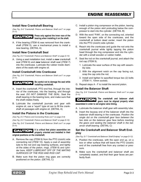
<strong>ENGINE</strong> REASSEMBLY<br />
Install New Crankshaft Bearing<br />
(See Fig. D-6 “Crankshaft, Pistons and Balancer Shaft con’t” on page<br />
D-11)<br />
Press only against the inner race of the<br />
bearing when installing it on the shaft.<br />
A. If the bearing (ITEM 4) was removed from the crankshaft<br />
(ITEM 5), use a mechanical press to install a<br />
new bearing. (DETAIL A)<br />
Install New Crankshaft Seal<br />
(See Fig. D-5 “Crankshaft, Pistons and Balancer Shaft” on page D-10)<br />
A. Using a seal installation tool, install a new crankshaft<br />
seal (ITEM 6) and new balancer shaft seal (ITEM 7)<br />
into the crankcase. Lubricate the rubber inside diameters<br />
of the seals with engine oil.<br />
Install Crankshaft into Crankcase<br />
(See Fig. D-6 “Crankshaft, Pistons and Balancer Shaft con’t” on page<br />
D-11)<br />
Be careful not to damage the seal while<br />
installing crankshaft.<br />
A. Insert the crankshaft, PTO end first, through the interior<br />
of the crankcase, into the bearing, and through<br />
the seal. DO NOT DAMAGE THE SEAL. Seat the<br />
shaft bearing in the bearing bore, and make sure that<br />
the shaft rotates freely.<br />
B. Lubricate the crankshaft journals and gear with<br />
engine oil, use a “squirt” type oil can to fill the crankshaft<br />
oil passages with engine oil. (DETAIL A)<br />
Install the Pistons in the Crankcase<br />
(See Fig. D-3 “Pistons and Connecting Rods con’t” on page D-8)<br />
(See Fig. D-5 “Crankshaft, Pistons and Balancer Shaft” on page D-10)<br />
(See Fig. D-6 “Crankshaft, Pistons and Balancer Shaft con’t” on page<br />
D-11)<br />
It is critical that piston assemblies are<br />
properly oriented and installed in their<br />
original positions on the crankshaft.<br />
A. Remove the cap (ITEM 9) from the PTO (clutch) side<br />
connecting rod (ITEM 10). Apply a coat of assembly<br />
lube to the rod and cap bearing surfaces, and lightly<br />
oil the sides of the piston, rings, (ITEM 8) and cylinder<br />
bore. KEEP LUBRICANT OFF OF THE MATING<br />
SURFACES OF THE ROD AND ROD CAP.<br />
B. Make sure that the piston ring gaps are correctly<br />
positioned on the piston. (DETAIL C)<br />
C. Install a piston ring compressor on the piston, leaving<br />
enough of the piston skirt protruding below the compressor<br />
to start into the cylinder. (DETAIL B)<br />
D. With the word “FAN“, on the connecting rod, oriented<br />
toward the open side of the crankcase, and the<br />
crankshaft at bottom dead center, insert the piston<br />
into the PTO (clutch) side cylinder.<br />
E. Reach into the crankcase and guide the rod onto the<br />
crankshaft journal while lightly tapping the piston<br />
head through the ring compressor and into the cylinder<br />
with a small wooden or rubber mallet.<br />
F. Seat the rod on the crankshaft journal, and attach the<br />
rod cap (ITEM 9).<br />
1. Lubricate the wear surface of the cap with assembly<br />
lube.<br />
2. With the alignment notch on the cap facing out,<br />
snap the cap onto the rod.<br />
3. Install and tighten to specified torque two (2) bolts<br />
(ITEM 11, 10mm socket).<br />
G. Repeat steps A - F to install the second piston.<br />
Install the Balancer Shaft<br />
(See Fig. D-6 “Crankshaft, Pistons and Balancer Shaft con’t” on page<br />
D-11)<br />
The crankshaft and balancer shaft<br />
gears must be aligned properly when<br />
assembled in order to set engine valve timing.<br />
A. Lubricate the balancer shaft gear with assembly lube.<br />
B. Insert the keyway end of the balancer shaft into the<br />
balancer shaft bearing in the crankcase. Position the<br />
single dot on the crankshaft gear face between the<br />
two dots on the balancer gear face before meshing<br />
the gears and seating the balancer shaft in the balancer<br />
shaft bearing. (DETAIL C)<br />
Set the Crankshaft and Balancer Shaft Endplay<br />
(See Fig. D-7 “Crankshaft and Balancer Shaft Endplay” on page D-12)<br />
A. Position the crankcase, with the open end up, on a<br />
box or other surface that will leave the PTO (clutch)<br />
end of the crankshaft free from any contact or pressure.<br />
B. Make sure the crankshaft and balancer shaft are<br />
completely seated, and that their gear faces are perfectly<br />
flush.<br />
Engine Shop Rebuild and Parts Manual<br />
Page D-3