ENGINE SHOP REBUILD & SERVICE PARTS MANUAL - Jacobsen
ENGINE SHOP REBUILD & SERVICE PARTS MANUAL - Jacobsen
ENGINE SHOP REBUILD & SERVICE PARTS MANUAL - Jacobsen

Create successful ePaper yourself
Turn your PDF publications into a flip-book with our unique Google optimized e-Paper software.
<strong>ENGINE</strong> MEASUREMENTS<br />
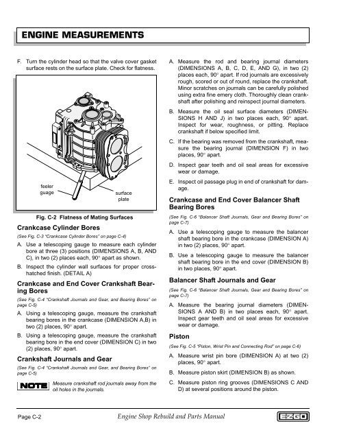
F. Turn the cylinder head so that the valve cover gasket<br />
surface rests on the surface plate. Check for flatness.<br />
feeler<br />
guage<br />
Crankcase Cylinder Bores<br />
(See Fig. C-3 “Crankcase Cylinder Bores” on page C-4)<br />
A. Use a telescoping gauge to measure each cylinder<br />
bore at three (3) positions (DIMENSIONS A, B, AND<br />
C), in two (2) places each, 90° apart as shown.<br />
B. Inspect the cylinder wall surfaces for proper crosshatched<br />
finish. (DETAIL A)<br />
Crankcase and End Cover Crankshaft Bearing<br />
Bores<br />
(See Fig. C-4 “Crankshaft Journals and Gear, and Bearing Bores” on<br />
page C-5)<br />
A. Using a telescoping gauge, measure the crankshaft<br />
bearing bores in the crankcase (DIMENSION A,B) in<br />
two (2) places, 90° apart.<br />
B. Using a telescoping gauge, measure the crankshaft<br />
bearing bore in the end cover (DIMENSION C) in two<br />
(2) places, 90° apart.<br />
Crankshaft Journals and Gear<br />
surface<br />
plate<br />
Fig. C-2 Flatness of Mating Surfaces<br />
(See Fig. C-4 “Crankshaft Journals and Gear, and Bearing Bores” on<br />
page C-5)<br />
Measure crankshaft rod journals away from the<br />
oil holes in the journals.<br />
A. Measure the rod and bearing journal diameters<br />
(DIMENSIONS A, B, C, D, E, AND G), in two (2)<br />
places each, 90° apart. If rod journals are excessively<br />
rough, scored or out of round, replace the crankshaft.<br />
Minor scratches on journals can be carefully polished<br />
using extra fine emery cloth. Thoroughly clean crankshaft<br />
after polishing and reinspect journal diameters.<br />
B. Measure the oil seal surface diameters (DIMEN-<br />
SIONS H AND J) in two places each, 90° apart.<br />
Inspect for wear, roughness, or pitting. Replace<br />
crankshaft if below specified limit.<br />
C. If the bearing was removed from the crankshaft, measure<br />
the bearing journal (DIMENSION F) in two<br />
places, 90° apart.<br />
D. Inspect gear teeth and oil seal areas for excessive<br />
wear or damage.<br />
E. Inspect oil passage plug in end of crankshaft for damage.<br />
Crankcase and End Cover Balancer Shaft<br />
Bearing Bores<br />
(See Fig. C-6 “Balancer Shaft Journals, Gear and Bearing Bores” on<br />
page C-7)<br />
A. Use a telescoping gauge to measure the balancer<br />
shaft bearing bore in the crankcase (DIMENSION A)<br />
in two (2) places, 90° apart.<br />
B. Use a telescoping gauge to measure the balancer<br />
shaft bearing bore in the end cover (DIMENSION B)<br />
in two places, 90° apart.<br />
Balancer Shaft Journals and Gear<br />
(See Fig. C-6 “Balancer Shaft Journals, Gear and Bearing Bores” on<br />
page C-7)<br />
A. Measure the bearing journal diameters (DIMEN-<br />
SIONS A AND B) in two places each, 90° apart.<br />
Inspect gear teeth and oil seal areas for excessive<br />
wear or damage.<br />
Piston<br />
(See Fig. C-5 “Piston, Wrist Pin and Connecting Rod” on page C-6)<br />
A. Measure wrist pin bore (DIMENSION A) at two (2)<br />
places, 90° apart.<br />
B. Measure piston skirt (DIMENSION B) as shown.<br />
C. Measure piston ring grooves (DIMENSIONS C AND<br />
D) at several positions around the piston.<br />
Page C-2<br />
Engine Shop Rebuild and Parts Manual