ENGINE SHOP REBUILD & SERVICE PARTS MANUAL - Jacobsen
ENGINE SHOP REBUILD & SERVICE PARTS MANUAL - Jacobsen
ENGINE SHOP REBUILD & SERVICE PARTS MANUAL - Jacobsen

Create successful ePaper yourself
Turn your PDF publications into a flip-book with our unique Google optimized e-Paper software.
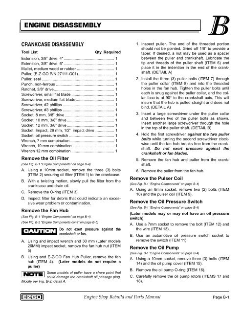
<strong>ENGINE</strong> DISASSEMBLY<br />
CRANKCASE DISASSEMBLY<br />
Tool List<br />
Qty. Required<br />
Extension, 3/8” drive, 4" .............................................. 1<br />
Extension, 3/8” drive, 6" .............................................. 1<br />
Mallet, medium wood or rubber .................................. 1<br />
Puller, (E-Z-GO P/N 27111-G01)................................. 1<br />
Puller, seal .................................................................. 1<br />
Punch, non-ferrous ..................................................... 1<br />
Ratchet, 3/8” drive....................................................... 1<br />
Screwdriver, small flat blade ....................................... 1<br />
Screwdriver, medium flat blade................................... 1<br />
Screwdriver, #2 phillips ............................................... 1<br />
Screwdriver, #3 phillips ............................................... 1<br />
Socket, 8 mm, 3/8” drive ............................................. 1<br />
Socket, 10 mm, 3/8” drive ........................................... 1<br />
Socket, 12 mm, 3/8” drive ........................................... 1<br />
Socket, Impact, 26 mm, 1/2” impact drive.................. 1<br />
Socket, oil pressure switch ......................................... 1<br />
Wrench, 7 mm combination ........................................ 1<br />
Wrench, 10 mm combination ...................................... 1<br />
Wrench 12 mm combination ....................................... 1<br />
Remove the Oil Filter<br />
(See Fig. B-1 “Engine Components” on page B-4)<br />
A. Using a 10mm socket, remove the three (3) bolts<br />
(ITEM 2) securing oil filter (ITEM 1) to the crankcase.<br />
B. With a twisting motion, slowly pull the filter from the<br />
crankcase and drain oil.<br />
C. Remove the O-ring (ITEM 3).<br />
D. Inspect filter for debris that could indicate an excessive<br />
wear problem or contamination.<br />
Remove the Fan Hub<br />
(See Fig. B-1 “Engine Components” on page B-4)<br />
(See Fig. B-2 “Engine Components con’t” on page B-5)<br />
Do not exert pressure against the<br />
crankshaft or fan.<br />
A. Using and impact wrench and 30 mm (Later models<br />
26MM) impact socket, remove the fan hub nut (ITEM<br />
5)<br />
B. Using and E-Z-GO Fan Hub Puller, remove the fan<br />
hub (ITEM 4). (Later models do not require a<br />
puller)<br />
Some models of puller have a sharp point that<br />
could damage the crankshaft oil passage plug.<br />
Modify per Fig. B-2, detail A.<br />
B<br />
1. Inspect puller. The end of the threaded portion<br />
should not be pointed. Grind off 1/8” to provide a<br />
taper. If desired, a nut may be used as a spacer<br />
between the puller and crankshaft. Lubricate the<br />
tip and threads of the puller shaft (ITEM 6) and<br />
place it in the indention in the end of the crankshaft.<br />
(DETAIL A)<br />
2. Install the three (3) puller bolts (ITEM 7) through<br />
the puller collar (ITEM 8) and into the threaded<br />
holes in the fan hub. Tighten the puller bolts until<br />
each is snug against the puller collar, and the collar<br />
face is at 90° to the crankshaft axis. This will<br />
insure that the hub is pulled straight and does not<br />
bind. (DETAIL A)<br />
3. Insert a large screwdriver under the puller collar<br />
and between two of the puller bolts as shown.<br />
Insert another large screwdriver through the hole<br />
in the top of the puller shaft. (DETAIL B)<br />
4. Hold the first screwdriver against the two puller<br />
bolts while turning the second screwdriver clockwise<br />
until the fan hub breaks free from the crankshaft.<br />
Do not exert pressure against the<br />
crankshaft or fan blades.<br />
5. Remove the fan hub and puller from the crankshaft.<br />
6. Remove the puller from the fan hub.<br />
Remove the Pulser Coil<br />
(See Fig. B-1 “Engine Components” on page B-4)<br />
A. Using an 8mm socket, remove two (2) bolts (ITEM<br />
10) and the pulser coil (ITEM 9).<br />
Remove the Oil Pressure Switch<br />
(See Fig. B-1 “Engine Components” on page B-4)<br />
(Later models may or may not have an oil pressure<br />
switch)<br />
A. Use a 7mm socket to remove the bolt (ITEM 12) and<br />
the wire (ITEM 13).<br />
B. Use an automotive oil pressure switch socket to<br />
remove the switch (ITEM 11)<br />
Remove the Oil Pump<br />
(See Fig. B-1 “Engine Components” on page B-4)<br />
A. Using a 10mm socket, remove three (3) bolts (ITEM<br />
14) and the oil pump cover (ITEM 15).<br />
B. Remove the oil pump O-ring (ITEM 16).<br />
C. Carefully remove the oil pump rotors (ITEMS 17 and<br />
18).<br />
Engine Shop Rebuild and Parts Manual<br />
Page B-1