Grundfos CU 300 Installation and Operating Instructions - Geotech
Grundfos CU 300 Installation and Operating Instructions - Geotech
Grundfos CU 300 Installation and Operating Instructions - Geotech

You also want an ePaper? Increase the reach of your titles
YUMPU automatically turns print PDFs into web optimized ePapers that Google loves.
7.5 Electrical connection<br />
Never make any connections in the<br />
<strong>CU</strong> <strong>300</strong> unit unless the electricity supply<br />
The supply voltage <strong>and</strong> frequency are marked on the<br />
nameplate. Make sure that the <strong>CU</strong> <strong>300</strong> is suitable for<br />
the electricity supply on which it will be used.<br />
has been switched off. The <strong>CU</strong> <strong>300</strong> must<br />
be connected in accordance with the rules<br />
<strong>and</strong> st<strong>and</strong>ards in force for the application<br />
in question.<br />
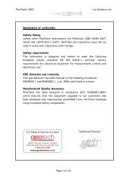
Fig. 31<br />
1 2<br />
3 4<br />
K1<br />
POWER<br />
PE<br />
PUMP<br />
5 6 7<br />
NC<br />
COM<br />
NO<br />
8 9 10<br />
NC<br />
COM<br />
NO<br />
111213 141516<br />
171819<br />
+24VDC<br />
IN<br />
GND<br />
+24VDC<br />
IN<br />
GND<br />
+24VDC<br />
IN<br />
GND<br />
B<br />
GND<br />
A RI<br />
DTR<br />
RXD<br />
GND<br />
TXD<br />
PE<br />
ALARM<br />
RELAY<br />
AUX<br />
RELAY<br />
DIG<br />
IN<br />
SENSOR SENSOR<br />
1 2<br />
RS<br />
485<br />
RS<br />
232<br />
H<br />
L N<br />
N<br />
L<br />
SENSOR IN<br />
DIG IN<br />
GND<br />
+24 VDC<br />
4 3 21<br />
SPP 1<br />
TM01 3091 3398<br />
Legend:<br />
Pos.<br />
Description<br />
K1<br />
Internal alarm signal relay<br />
Relay data: 250 VAC, 8 A, AC1<br />
H Alarm signal transmitter (optional)<br />
SPP 1 External <strong>Grundfos</strong> potentiometer, SPP 1<br />
7.5.1 Mains supply<br />
POWER, terminals 1, 2 <strong>and</strong> PE:<br />
Connect terminals 1 <strong>and</strong> 2 to the phase <strong>and</strong> neutral<br />
leads of the mains supply. Each terminal can be connected<br />
to any of the two leads.<br />
Connect the PE terminal to the green/yellow earth<br />
lead. Each PE terminal must be connected to an<br />
earth lead of its own.<br />
Maximum cross-section of the leads to be connected<br />
is 6 mm².<br />
Back-up fuse: Maximum 16 A.<br />
Note: The leads of the mains supply must not be<br />
connected to terminals 3 <strong>and</strong> 4 (PUMP).<br />
28