Grundfos CU 300 Installation and Operating Instructions - Geotech
Grundfos CU 300 Installation and Operating Instructions - Geotech
Grundfos CU 300 Installation and Operating Instructions - Geotech

You also want an ePaper? Increase the reach of your titles
YUMPU automatically turns print PDFs into web optimized ePapers that Google loves.
GRUNDFOS INSTRUCTIONS<br />
<strong>CU</strong> <strong>300</strong><br />
<strong>Installation</strong> <strong>and</strong> operating instructions<br />
For Sales & Service Contact<br />
2650 E. 40th Ave. • Denver, CO 80205<br />
Phone 303-320-4764 • Fax 303-322-7242<br />
1-800-833-7958<br />
www.geotechenv.com<br />
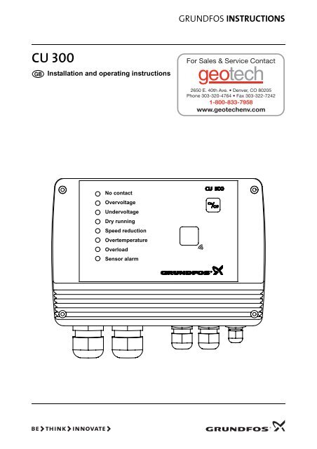
No contact<br />
Overvoltage<br />
Undervoltage<br />
Dry running<br />
Speed reduction<br />
Overtemperature<br />
Overload<br />
Sensor alarm
Declaration of Conformity<br />
We <strong>Grundfos</strong> declare under our sole responsibility that the product <strong>CU</strong> <strong>300</strong>, to which this<br />
declaration relates, is in conformity with the Council Directives on the approximation of the<br />
laws of the EC Member States relating to<br />
— Electromagnetic compatibility (89/336/EEC).<br />
St<strong>and</strong>ards used: EN 55 014 <strong>and</strong> EN 55 014-2.<br />
— Electrical equipment designed for use within certain voltage limits (73/23/EEC) [95].<br />
St<strong>and</strong>ard used: EN 60 335-1.<br />
Bjerringbro, 15th December 2004<br />
Jan Str<strong>and</strong>gaard<br />
Technical Manager<br />
2
CONTENTS<br />
Page<br />
1. General 5<br />
1.1 Expansion possibilities 5<br />
1.2 On/Off button 5<br />
2. <strong>CU</strong> <strong>300</strong> as an alarm unit 6<br />
2.1 Description 6<br />
2.2 <strong>Installation</strong> 6<br />
2.3 Location 6<br />
2.4 Mounting the <strong>CU</strong> <strong>300</strong> 6<br />
2.5 Electrical connection 7<br />
2.5.1 Mains supply 7<br />
2.5.2 Pump supply 7<br />
2.5.3 Alarm signal relay 7<br />
2.5.4 Digital input 7<br />
2.6 Description of dry-running protection 8<br />
2.6.1 Function 8<br />
2.7 Settings 8<br />
2.7.1 Required R100 settings 8<br />
2.8 Description of the dewatering function 8<br />
2.8.1 Applications 8<br />
2.8.2 Function 9<br />
2.9 Settings 9<br />
2.9.1 Required R100 settings 9<br />
2.9.2 Run/stop times 9<br />
3. <strong>CU</strong> <strong>300</strong> with constant pressure<br />
control - 0 to 6 bar 10<br />
3.1 Description 10<br />
3.2 Function 10<br />
3.3 Positioning the pressure sensor 11<br />
3.4 System sizing 12<br />
3.5 <strong>Installation</strong> 12<br />
3.6 Location 12<br />
3.7 Mounting the <strong>CU</strong> <strong>300</strong> 12<br />
3.8 Electrical connection 13<br />
3.8.1 Mains supply 13<br />
3.8.2 Pump supply 14<br />
3.8.3 Alarm signal relay 14<br />
3.9 Settings 14<br />
3.9.1 Required R100 settings 14<br />
3.10 Start-up 14<br />
4. <strong>CU</strong> <strong>300</strong> with constant pressure<br />
control - 0 to 10 bar 15<br />
4.1 Description 15<br />
4.2 Function 15<br />
4.3 Positioning the pressure sensor 15<br />
4.4 System sizing 16<br />
4.5 <strong>Installation</strong> 16<br />
4.6 Location 16<br />
4.7 Mounting the <strong>CU</strong> <strong>300</strong> 16<br />
4.8 Electrical connection 17<br />
4.8.1 Mains supply 17<br />
4.8.2 Pump supply 18<br />
4.8.3 Alarm signal relay 18<br />
4.9 Settings 18<br />
4.9.1 Required R100 settings 18<br />
4.10 Start-up 18<br />
5. <strong>CU</strong> <strong>300</strong> with constant pressure<br />
control - two-pump operation 19<br />
5.1 Description 19<br />
5.2 Function 19<br />
5.3 Positioning the pressure sensor 20<br />
5.4 System sizing 20<br />
5.5 <strong>Installation</strong> 20<br />
5.6 Location 20<br />
5.7 Mounting the <strong>CU</strong> <strong>300</strong> 20<br />
5.8 Electrical connection 21<br />
5.8.1 Auxiliary relay 21<br />
5.8.2 Mains supply 21<br />
5.8.3 Pump supply 22<br />
5.8.4 Alarm signal relay 22<br />
5.8.5 Flow switch <strong>and</strong> pressure sensor 22<br />
5.9 Settings 22<br />
5.9.1 Required R100 settings 22<br />
5.10 Start-up 22<br />
6. <strong>CU</strong> <strong>300</strong> with sensors 23<br />
6.1 General 23<br />
6.2 Sensor functioning 23<br />
6.2.1 Alarm limits 23<br />
6.2.2 Warning limits 23<br />
6.2.3 Start/stop limits 23<br />
6.3 <strong>Installation</strong> 24<br />
6.4 Location 24<br />
6.5 Mounting the <strong>CU</strong> <strong>300</strong> 24<br />
6.6 Electrical connection 25<br />
6.6.1 Mains supply 25<br />
6.6.2 Pump supply 26<br />
6.6.3 Alarm signal relay 26<br />
6.6.4 Sensors 26<br />
6.7 Settings 26<br />
6.7.1 Required R100 settings 26<br />
7. <strong>CU</strong> <strong>300</strong> connected to<br />
potentiometer 27<br />
7.1 Description 27<br />
7.2 <strong>Installation</strong> 27<br />
7.3 Location 27<br />
7.4 Mounting the <strong>CU</strong> <strong>300</strong> 27<br />
7.5 Electrical connection 28<br />
7.5.1 Mains supply 28<br />
7.5.2 Pump supply 29<br />
7.5.3 Alarm signal relay 29<br />
7.5.4 Potentiometer SPP 1 29<br />
7.6 Settings 29<br />
7.6.1 Required R100 settings 29<br />
8. <strong>CU</strong> <strong>300</strong> connected to water meter 30<br />
8.1 Description 30<br />
8.2 <strong>Installation</strong> 30<br />
8.3 Location 30<br />
8.4 Mounting the <strong>CU</strong> <strong>300</strong> 30<br />
8.5 Electrical connection 31<br />
8.5.1 Mains supply 31<br />
8.5.2 Pump supply 31<br />
8.5.3 Alarm signal relay 31<br />
8.5.4 Water meter (pulse flow meter) 32<br />
8.6 Settings 32<br />
8.6.1 Required R100 settings 32<br />
3
9. Constant water level 33<br />
9.1 Description 33<br />
9.2 Function 33<br />
9.3 <strong>Installation</strong> 33<br />
9.4 Location 33<br />
9.5 Mounting the <strong>CU</strong> <strong>300</strong> 33<br />
9.6 Electrical connection 34<br />
9.6.1 Mains supply 34<br />
9.6.2 Pump supply 35<br />
9.6.3 Alarm signal relay 35<br />
9.6.4 Level sensor 35<br />
9.7 Settings 35<br />
9.7.1 Required R100 settings 35<br />
10. <strong>CU</strong> <strong>300</strong> connected to RS-232,<br />
RS-485 36<br />
10.1 Description 36<br />
10.2 <strong>CU</strong> <strong>300</strong> connected to a PC directly 36<br />
10.3 <strong>Installation</strong> 37<br />
10.4 Location 37<br />
10.5 Mounting the <strong>CU</strong> <strong>300</strong> 37<br />
10.6 Electrical connection 38<br />
10.6.1 Mains supply 38<br />
10.6.2 Pump supply 38<br />
10.6.3 Alarm signal relay 39<br />
10.6.4 RS-485 input 39<br />
10.6.5 RS-232 input 39<br />
10.6.6 Modem 39<br />
10.6.7 PC Tool <strong>CU</strong> <strong>300</strong> 39<br />
11. Alarm functions 40<br />
11.1 No contact 40<br />
11.2 Overvoltage 40<br />
11.3 Undervoltage 40<br />
11.4 Dry running 41<br />
11.5 Speed reduction 41<br />
11.6 Overtemperature 41<br />
11.7 Overload 42<br />
11.8 Sensor alarm 42<br />
12. <strong>CU</strong> <strong>300</strong> with R100 43<br />
12.1 Menu OPERATION 47<br />
12.1.1 Setpoint 47<br />
12.1.2 <strong>Operating</strong> mode 47<br />
12.1.3 Alarm 47<br />
12.2 Menu STATUS 48<br />
12.2.1 <strong>Operating</strong> mode 48<br />
12.2.2 Actual setpoint <strong>and</strong> external setpoint 48<br />
12.2.3 Temperature 49<br />
12.2.4 Speed 49<br />
12.2.5 Power input <strong>and</strong> power consumption 49<br />
12.2.6 <strong>Operating</strong> hours <strong>and</strong> number of starts 49<br />
12.2.7 Sensor 1 <strong>and</strong> sensor 2 49<br />
12.2.8 Digital input 49<br />
12.2.9 Accumulated flow <strong>and</strong> energy per m³ 50<br />
12.3 Menu LIMITS 50<br />
12.3.1 Sensor 1 50<br />
12.3.2 Stop, sensor 1 50<br />
12.3.3 Warning, sensor 1 50<br />
12.3.4 Alarm, sensor 1 50<br />
12.3.5 Sensor 2 51<br />
12.3.6 Stop, sensor 2 51<br />
12.3.7 Warning, sensor 2 51<br />
12.3.8 Alarm, sensor 2 51<br />
12.3.9 Stop type 51<br />
12.3.10 Digital input 52<br />
12.3.11 Accumulated flow 52<br />
12.3.12 Warning, temperature 52<br />
12.4 Menu INSTALLATION 52<br />
12.4.1 Controller 52<br />
12.4.2 External setpoint 53<br />
12.4.3 Automatic restart 53<br />
12.4.4 Start delay 54<br />
12.4.5 Run/Stop 54<br />
12.4.6 Dry-running stop 54<br />
12.4.7 Dry-running protection 54<br />
12.4.8 Maximum speed 55<br />
12.4.9 Button on <strong>CU</strong> <strong>300</strong> 55<br />
12.4.10 Number 55<br />
13. Technical data 56<br />
14. Disposal 57<br />
4
1. General<br />
Before beginning installation procedures,<br />
these installation <strong>and</strong> operating instructions<br />
should be studied carefully. The installation<br />
<strong>and</strong> operation should also be in<br />
accordance with local regulations <strong>and</strong> accepted<br />
codes of good practice.<br />
The control unit <strong>CU</strong> <strong>300</strong> is developed for the SQE<br />
submersible pumps.<br />
The <strong>CU</strong> <strong>300</strong> covers the voltage range:<br />
1 x 100-240 V –10%/+6%, 50/60 Hz, PE.<br />
The <strong>CU</strong> <strong>300</strong> enables:<br />
• control of the pump on the basis of sensor signals,<br />
• setting of operating parameters, <strong>and</strong><br />
• monitoring of operation <strong>and</strong> alarm indication, if<br />
any.<br />
The <strong>CU</strong> <strong>300</strong> indicates the following alarms:<br />
• No contact,<br />
• Overvoltage,<br />
• Undervoltage,<br />
• Dry running,<br />
• Speed reduction,<br />
• Overtemperature,<br />
• Overload,<br />
• Sensor alarm.<br />
The individual alarms are described in detail in section<br />
11. Alarm functions.<br />
The <strong>CU</strong> <strong>300</strong> receives alarm signals from the motor<br />
for the following parameters:<br />
• Dry running.<br />
• Incipient pump/motor defect.<br />
• Too high temperature in motor electronics.<br />
• Supply failure.<br />
As st<strong>and</strong>ard, the <strong>CU</strong> <strong>300</strong> incorporates an alarm signal<br />
relay.<br />
1.1 Expansion possibilities<br />
The <strong>CU</strong> <strong>300</strong> enables the use of:<br />
• Remote control R100:<br />
Wireless infra-red remote control by means of the<br />
R100 enables change of factory settings <strong>and</strong> monitoring<br />
of the installation by calling up actual operating<br />
data, e.g. speed, operating hours <strong>and</strong> power<br />
consumption.<br />
• External sensors:<br />
Reception of data from external sensors <strong>and</strong> control<br />
according to the data received, e.g. flow rate,<br />
pressure, water level <strong>and</strong> conductivity.<br />
• External potentiometer SPP 1:<br />
Manual speed control.<br />
1.2 On/Off button<br />
By means of the On/Off button on the <strong>CU</strong> <strong>300</strong>, it is<br />
possible to<br />
• start/stop the pump <strong>and</strong><br />
• reset possible alarms.<br />
Fig. 1<br />
The green <strong>and</strong> red indicator lights in the On/Off button<br />
indicate pump operating condition as follows:<br />
Indication<br />
Green indicator light<br />
permanently on.<br />
Green indicator light<br />
flashing.<br />
Red indicator light<br />
permanently on.<br />
Red indicator light<br />
flashing.<br />
Green<br />
Description<br />
Red<br />
Pump is operating.<br />
* If the On/Off button has been used to stop the<br />
pump, this button must also be used for restarting.<br />
If the On/Off button is pressed for minimum 5 seconds,<br />
the pump is started, irrespective of any active<br />
fault/alarm indications. When the On/Off button is<br />
released, the pump will stop.<br />
TM01 2829 4601<br />
Pump has been stopped by<br />
either:<br />
• a sensor,<br />
• an external on/off switch<br />
or<br />
• a stop comm<strong>and</strong> from the<br />
R100.<br />
Pump has been stopped by<br />
means of the On/Off button.*<br />
The <strong>CU</strong> <strong>300</strong> is communicating<br />
with the R100.<br />
5
2. <strong>CU</strong> <strong>300</strong> as an alarm unit<br />
2.1 Description<br />
When the <strong>CU</strong> <strong>300</strong> is connected to an SQE pump,<br />
any alarm will be indicated by one of the eight red<br />
indicator lights on the <strong>CU</strong> <strong>300</strong>.<br />
The indications are based on signals from the motor<br />
<strong>and</strong> from sensors, if installed. The individual alarms<br />
are described in detail in section 11. Alarm functions.<br />
It is possible to connect an external alarm signal<br />
transmitter <strong>and</strong> an external on/off switch, see section<br />
2.5 Electrical connection concerning connection, etc.<br />
Fig. 2 shows an example of an installation with the<br />
<strong>CU</strong> <strong>300</strong> as an alarm unit.<br />
Fig. 2<br />
2.4 Mounting the <strong>CU</strong> <strong>300</strong><br />
The <strong>CU</strong> <strong>300</strong> is designed for wall mounting.<br />
The box has six mounting holes (ø4), see fig. 3<br />
(dimensions stated in mm).<br />
The <strong>CU</strong> <strong>300</strong> must be mounted:<br />
• horizontally (see fig. 3) to allow condensed water,<br />
if any, to escape.<br />
• on a plane surface to avoid deformation of the<br />
box.<br />
Fig. 3<br />
104.5<br />
104.5<br />
TM01 2824 2498<br />
100<br />
TM01 3150 4601<br />
140.5<br />
The <strong>CU</strong> <strong>300</strong> is supplied with a set of gaskets for the<br />
Pg screwed connections.<br />
The gaskets are to be used for the connection of<br />
cables/wires to ensure tight connections (IP 55) <strong>and</strong><br />
cable relief.<br />
The <strong>CU</strong> <strong>300</strong> functions as an alarm unit for the pump.<br />
Furthermore, it is possible to communicate with the<br />
pump via the remote control R100, see also section<br />
12. <strong>CU</strong> <strong>300</strong> with R100.<br />
2.2 <strong>Installation</strong><br />
2.3 Location<br />
Before starting any work on the <strong>CU</strong> <strong>300</strong>,<br />
make sure that the electricity supply has<br />
been switched off <strong>and</strong> that it cannot be accidentally<br />
switched on.<br />
The <strong>CU</strong> <strong>300</strong> can be placed both indoors <strong>and</strong> outdoors.<br />
It must not be exposed to direct sunlight.<br />
6
2.5 Electrical connection<br />
Never make any connections in the<br />
<strong>CU</strong> <strong>300</strong> unit unless the electricity supply<br />
The supply voltage <strong>and</strong> frequency are marked on the<br />
nameplate. Make sure that the <strong>CU</strong> <strong>300</strong> is suitable for<br />
the electricity supply on which it will be used.<br />
has been switched off. The <strong>CU</strong> <strong>300</strong> must<br />
be connected in accordance with the rules<br />
<strong>and</strong> st<strong>and</strong>ards in force for the application<br />
in question.<br />
Fig. 4<br />
1 2<br />
3 4<br />
K1<br />
POWER<br />
PE<br />
PUMP<br />
5 6 7<br />
NC<br />
COM<br />
NO<br />
8 9 10<br />
NC<br />
COM<br />
NO<br />
111213 141516<br />
171819<br />
+24VDC<br />
IN<br />
GND<br />
+24VDC<br />
IN<br />
GND<br />
+24VDC<br />
IN<br />
GND<br />
B<br />
GND<br />
A RI<br />
DTR<br />
RXD<br />
GND<br />
TXD<br />
PE<br />
ALARM<br />
RELAY<br />
AUX<br />
RELAY<br />
DIG<br />
IN<br />
SENSOR SENSOR<br />
1 2<br />
RS<br />
485<br />
RS<br />
232<br />
L<br />
N<br />
N<br />
L<br />
H<br />
S1<br />
TM01 3067 3398<br />
Legend:<br />
Pos.<br />
S1<br />
H<br />
K1<br />
Description<br />
On/off switch for start/stop of pump<br />
Alarm signal transmitter (optional)<br />
Internal alarm signal relay<br />
Relay data: 250 VAC, 8 A, AC1<br />
2.5.1 Mains supply<br />
POWER, terminals 1, 2 <strong>and</strong> PE:<br />
Connect terminals 1 <strong>and</strong> 2 to the phase <strong>and</strong> neutral<br />
leads of the mains supply. Each terminal can be connected<br />
to any of the two leads.<br />
Connect the PE terminal to the green/yellow earth<br />
lead. Each PE terminal must be connected to an<br />
earth lead of its own.<br />
Maximum cross-section of the leads to be connected<br />
is 6 mm².<br />
Back-up fuse: Maximum 16 A.<br />
Note: The leads of the mains supply must not be<br />
connected to terminals 3 <strong>and</strong> 4 (PUMP).<br />
2.5.2 Pump supply<br />
PUMP, terminals 3, 4 <strong>and</strong> PE:<br />
Connect terminals 3 <strong>and</strong> 4 to the phase <strong>and</strong> neutral<br />
leads of the pump. Each terminal can be connected<br />
to any of the two leads.<br />
Connect the PE terminal to the green/yellow earth<br />
lead. Each PE terminal must be connected to an<br />
earth lead of its own.<br />
Maximum cross-section of the leads to be connected<br />
is 6 mm².<br />
2.5.3 Alarm signal relay<br />
ALARM RELAY, terminals 5, 6 <strong>and</strong> 7:<br />
Connect terminals 5, 6 <strong>and</strong> 7 to the internal alarm<br />
signal relay as follows:<br />
• Terminal 5 NC (normally closed).<br />
• Terminal 6 COM (common).<br />
• Terminal 7 NO (normally open).<br />
The relay is activated when the alarm <strong>and</strong> warning<br />
limits are exceeded.<br />
Manual or automatic restarting can be selected in the<br />
R100 display 12.4.3 Automatic restart.<br />
Manual restarting is carried out by means of the<br />
On/Off button on the <strong>CU</strong> <strong>300</strong>.<br />
2.5.4 Digital input<br />
DIG IN, terminals 11, 12 <strong>and</strong> 13:<br />
In fig. 4, the digital input is used to start <strong>and</strong> stop the<br />
pump.<br />
The function of the digital input can be selected by<br />
means of the R100 in display 12.3.10 Digital input.<br />
7
2.6 Description of dry-running protection<br />
When the pump sucks air, the pump power input<br />
decreases.<br />
If the pump power input falls below the dry-running<br />
power limit set in the R100 display 12.4.6 Dry-running<br />
stop, the pump will stop <strong>and</strong> the <strong>CU</strong> <strong>300</strong> will<br />
indicate the dry-running alarm.<br />
2.6.1 Function<br />
The dry-running protection applies only if the motor<br />
speed lies within the “maximum speed” range (i.e.<br />
maximum speed less 1,000 min -1 ), see fig. 5.<br />
Normally, “maximum speed” is 10,700 min -1 . However,<br />
it can be reduced in the R100 display 12.4.8<br />
Maximum speed. The dry-running power limit set in<br />
display 12.4.6 Dry-running stop must match the<br />
speed.<br />
Changing the setpoint:<br />
If the setpoint is changed by means of the R100 display<br />
12.1.1 Setpoint or 12.4.2 External setpoint, the<br />
pump can be forced to run at a reduced speed in<br />
relation to the “maximum speed”. The dry-running<br />
protection will not protect the pump if the reduced<br />
speed lies outside the “maximum speed” range (i.e.<br />
maximum speed less 1,000 min -1 ), see fig. 5.<br />
Constant pressure control:<br />
In constant pressure control mode, the dry-running<br />
protection is active, as the motor will operate at<br />
“maximum speed” in connection with dry running.<br />
Pump power input curve:<br />
The curve shows the pump power input in relation to<br />
the pump speed.<br />
Fig. 5<br />
Pump<br />
power input<br />
Watt<br />
3,000 min -1<br />
Pump power curve<br />
Dry-running<br />
power limit set<br />
Motor speed<br />
Max. speed Max. speed<br />
-1,000 min -1 as set in display<br />
12.4.8<br />
2.7 Settings<br />
In the following section, the relevant R100 displays<br />
<strong>and</strong> settings are shown <strong>and</strong> described.<br />
For a detailed description of the R100 displays, see<br />
section 12. <strong>CU</strong> <strong>300</strong> with R100. Each individual display<br />
has a number which refers to the section in<br />
which it is described in detail.<br />
TM01 2689 2598<br />
2.7.1 Required R100 settings<br />
If the maximum speed of the pump has been reduced<br />
by more than 1,000 min -1 , the dry-running<br />
stop value must be changed. In order to change the<br />
dry-running protection function, the following R100<br />
settings must be made:<br />
Display R100 setting<br />
Set “Dry-running protection”<br />
to “Active”.<br />
12.4.7 Dry-running Note: In certain installations,<br />
protection it may be necessary to disable<br />
the dry-running protection.<br />
This is done in this<br />
display. The disabling applies<br />
to the dry-running power<br />
limit set in display 12.4.6 Dryrunning<br />
stop.<br />
See fig. 5.<br />
12.4.6 Dry-running<br />
stop<br />
Set the dry-running power<br />
limit, i.e. dry-running stop.<br />
See “Setting of dry-running<br />
power limit (dry-running<br />
stop)” below <strong>and</strong> section 13.<br />
Technical data.<br />
Setting of dry-running power limit (dry-running<br />
stop):<br />
1. Start the pump against a closed discharge pipe.<br />
2. Read the input power (P 1 ) in the R100 display<br />
12.2.5 Power input <strong>and</strong> power consumption.<br />
3. Calculate the dry-running power limit,<br />
P 1 x 0.9 [W].<br />
4. Set this value in the R100 display 12.4.6 Dry-running<br />
stop.<br />
2.8 Description of the dewatering function<br />
When the pump sucks air, the pump power input<br />
decreases.<br />
If the pump power input falls below the dry-running<br />
power limit set in the R100 display 12.4.6 Dry-running<br />
stop, the pump will stop.<br />
During dewatering, the green indicator light in the<br />
On/Off button on the <strong>CU</strong> <strong>300</strong> is flashing to indicate<br />
that the pump has stopped.<br />
2.8.1 Applications<br />
The dewatering function can be used in applications<br />
where the pump often runs dry, e.g.:<br />
• in boreholes with a low yield.<br />
• in boreholes <strong>and</strong> building sites where the water<br />
table should be lowered.<br />
8
2.8.2 Function<br />
The dewatering function works as follows:<br />
1. The pump is operating.<br />
2. The pump sucks air due to a drop in the water<br />
level.<br />
3. The load decreases, <strong>and</strong> consequently the pump<br />
power input does as well.<br />
4. The pump stops when the power input falls to the<br />
dry-running power limit set in the R100 display<br />
12.4.6 Dry-running stop in the INSTALLATION<br />
menu.<br />
Note: The length of the stop time depends on the<br />
length of the run time according to a setting made<br />
in the R100 display 12.4.5 Run/Stop in the IN-<br />
STALLATION menu.<br />
2.9 Settings<br />
In the following section, the relevant R100 displays<br />
<strong>and</strong> settings are shown <strong>and</strong> described.<br />
For a detailed description of the R100 displays, see<br />
section 12. <strong>CU</strong> <strong>300</strong> with R100. Each individual display<br />
has a number which refers to the section in<br />
which it is described in detail.<br />
2.9.1 Required R100 settings<br />
In order to activate the dewatering function, the following<br />
R100 settings must be made:<br />
Display R100 setting<br />
12.4.7 Dry-running<br />
protection<br />
Set “Dry-running protection”<br />
to “Active”.<br />
12.4.6 Dry-running<br />
stop<br />
Set the dry-running power<br />
limit, i.e. dry-running stop.<br />
See “Setting of dry-running<br />
power limit (dry-running<br />
stop)” below.<br />
Setting of dry-running power limit (dry-running<br />
stop):<br />
1. Start the pump against a closed discharge pipe.<br />
2. Read the input power (P 1 ) in the R100 display<br />
12.2.5 Power input <strong>and</strong> power consumption.<br />
3. Calculate the dry-running power limit,<br />
P 1 x 0.9 [W].<br />
4. Set this value in the R100 display 12.4.6 Dry-running<br />
stop.<br />
2.9.2 Run/stop times<br />
The dewatering function means that there is a dependence<br />
between the period of time during which<br />
the pump is running, the run time, <strong>and</strong> the period of<br />
time during which the pump is stopped, the stop<br />
time.<br />
Fig. 6 shows an example of run/stop times set in the<br />
R100 display 12.4.5 Run/Stop.<br />
Fig. 6<br />
Explanation:<br />
The run <strong>and</strong> stop times were set to 60 min. each.<br />
The pump has been running for 25 min. when dry<br />
running occurs. The pump will be stopped for 35 min.<br />
If the pump had been running for e.g. 2 hours<br />
(120 min.), the stop time would be 1 min.<br />
TM01 2690 2298<br />
12.4.5 Run/Stop<br />
Set the relation between run<br />
<strong>and</strong> stop times.<br />
Indication of operation:<br />
The dry-running alarm indication<br />
on the <strong>CU</strong> <strong>300</strong> is automatically<br />
disabled, when the<br />
setting is made in display<br />
12.4.5 Run/Stop.<br />
To disable the dewatering<br />
function <strong>and</strong> return to dryrunning<br />
protection, simply set<br />
the Run/Stop fields to “–”<br />
(not active).<br />
9
3. <strong>CU</strong> <strong>300</strong> with constant pressure<br />
control - 0 to 6 bar<br />
3.1 Description<br />
Using constant pressure control enables automatic<br />
adjustment of the pump performance according to<br />
consumption. The system maintains a constant pressure<br />
within the maximum pump performance in spite<br />
of a varying water consumption.<br />
Fig. 7 shows an example of an installation with constant<br />
pressure control within the range from 0 to<br />
6 bar.<br />
Fig. 7<br />
When does the pump start<br />
The pump starts as a consequence of...<br />
• a high flow or<br />
• a low pressure or<br />
• a combination of both.<br />
To ensure that the pump is started when water is<br />
consumed, a flow detection is required. The flow is<br />
detected via pressure changes in the system. When<br />
water is consumed, the pressure will drop accordingly<br />
depending on the size of the diaphragm tank <strong>and</strong><br />
the water flow:<br />
• at a low flow, the pressure will drop slowly.<br />
• at a high flow, the pressure will drop quickly.<br />
See fig. 8.<br />
Fig. 8<br />
Pressure<br />
Low flow<br />
Pos. Description<br />
1 <strong>CU</strong> <strong>300</strong><br />
2<br />
3<br />
Diaphragm tank<br />
Absorbs pressure variations.<br />
Pressure sensor<br />
The required pressure is set using the<br />
R100.<br />
3.2 Function<br />
The pressure is registered by means of the pressure<br />
sensor, which transmits a signal to the <strong>CU</strong> <strong>300</strong>. The<br />
<strong>CU</strong> <strong>300</strong> adjusts the pump performance accordingly<br />
by changing the pump speed.<br />
Mains borne signalling:<br />
The communication between the <strong>CU</strong> <strong>300</strong> <strong>and</strong> the<br />
pump is effected via the power supply cable.<br />
This communication principle is called mains borne<br />
signalling (or power line communication). Using this<br />
principle means that no additional cables to the<br />
pump are required.<br />
The communication of data is effected by means of a<br />
high-frequency signal transmitted to the power supply<br />
cable <strong>and</strong> led into the electronics unit by means<br />
of signal coils incorporated in the motor <strong>and</strong> the<br />
<strong>CU</strong> <strong>300</strong> respectively.<br />
TM01 9649 4601<br />
High flow<br />
Time<br />
Note: When the pressure is dropping 0.1 bar/s or<br />
faster, the pump will start immediately.<br />
If a diaphragm tank of 8 litres is used, the pump will<br />
start at a flow rate of approx. 0.18 m³/h.<br />
Note: If a larger tank is used, the flow must be<br />
higher before the pump starts.<br />
Consumption up to 0.18 m³/h:<br />
The pump will start when the pressure has dropped<br />
to 0.5 bar below the pressure setting.<br />
The pump will run until the pressure is 0.5 bar above<br />
the pressure set.<br />
Flow detection:<br />
During pump operation, i.e. when water is consumed,<br />
the <strong>CU</strong> <strong>300</strong> will adjust the pump speed to<br />
maintain a constant pressure. In order to stop the<br />
pump when no water is consumed, the <strong>CU</strong> <strong>300</strong> performs<br />
flow detection every 10 seconds.<br />
The pump speed is reduced until a small pressure<br />
drop is registered. This pressure drop indicates that<br />
water is consumed <strong>and</strong> the pump speed is resumed,<br />
see fig. 9.<br />
If the pump speed can be reduced without any pressure<br />
drop being registered, this indicates that no<br />
water is consumed. The diaphragm tank will be filled<br />
with water <strong>and</strong> the pump will be stopped.<br />
TM01 8545 0400<br />
10
Fig. 9<br />
Pressure<br />
Flow detection<br />
3.3 Positioning the pressure sensor<br />
Pressure loss often causes inconvenience to the<br />
user. The <strong>CU</strong> <strong>300</strong> keeps the pressure constant in the<br />
place where the pressure sensor is positioned, see<br />
fig. 11.<br />
Fig. 11<br />
10 s<br />
10 s<br />
Time<br />
TM01 8546 0400<br />
<strong>CU</strong> <strong>300</strong><br />
8 l<br />
Shower<br />
System limits:<br />
Even though the <strong>CU</strong> <strong>300</strong> is controlling the pressure<br />
within ±0.2 bar, bigger pressure variations may occur<br />
in the system.<br />
If the consumption is suddenly changed, e.g. if a tap<br />
is opened, the water must start flowing before the<br />
pressure can be made constant again. Such dynamic<br />
variations depend on the pipework, but, typically,<br />
they will lie between 0.5 <strong>and</strong> 1 bar.<br />
If the desired consumption is higher than the quantity<br />
the pump is able to deliver at the desired pressure,<br />
the pressure follows the pump curve as illustrated in<br />
fig. 10.<br />
Fig. 10<br />
A<br />
Pressure<br />
Stop<br />
+0.5 bar<br />
Tap 1 Tap 2<br />
In fig. 11, tap 1 is placed close to the pressure sensor.<br />
Therefore, the pressure will be kept nearly constant<br />
at tap 1, as the friction loss is small. At the<br />
shower <strong>and</strong> tap 2, the friction loss is bigger. This, of<br />
course, depends on the piping. However, old <strong>and</strong><br />
furred-up piping may cause inconvenience due to<br />
friction loss.<br />
Therefore, it is recommended that the pressure sensor<br />
be positioned as close to the places of consumption<br />
as possible.<br />
TM01 9670 4601<br />
Start<br />
-0.5 bar<br />
0.18<br />
Controlling<br />
±0.2 bar<br />
Dynamic<br />
variations<br />
±0.5 bar<br />
Flow Flow<br />
m³/h<br />
TM01 8634 0500<br />
A = Required pressure<br />
11
3.4 System sizing<br />
In normal installations with the <strong>CU</strong> <strong>300</strong> <strong>and</strong> an SQE<br />
pump set to constant pressure control, the required<br />
tank size is 8 litres. Bigger tanks can be used without<br />
causing any problems.<br />
3.5 <strong>Installation</strong><br />
3.6 Location<br />
The installation must be designed for the<br />
maximum pump pressure.<br />
Before starting any work on the <strong>CU</strong> <strong>300</strong>,<br />
make sure that the electricity supply has<br />
been switched off <strong>and</strong> that it cannot be accidentally<br />
switched on.<br />
The <strong>CU</strong> <strong>300</strong> can be placed both indoors <strong>and</strong> outdoors.<br />
It must not be exposed to direct sunlight.<br />
3.7 Mounting the <strong>CU</strong> <strong>300</strong><br />
The <strong>CU</strong> <strong>300</strong> is designed for wall mounting.<br />
The box has six mounting holes (ø4), see fig. 12<br />
(dimensions stated in mm).<br />
The <strong>CU</strong> <strong>300</strong> must be mounted:<br />
• horizontally (see fig. 12) to allow condensed water,<br />
if any, to escape.<br />
• on a plane surface to avoid deformation of the<br />
box.<br />
Fig. 12<br />
104.5<br />
104.5<br />
TM01 2824 2498<br />
100<br />
140.5<br />
The <strong>CU</strong> <strong>300</strong> is supplied with a set of gaskets for the<br />
Pg screwed connections.<br />
The gaskets are to be used for the connection of<br />
cables/wires to ensure tight connections (IP 55) <strong>and</strong><br />
cable relief.<br />
12
3.8 Electrical connection<br />
Never make any connections in the<br />
<strong>CU</strong> <strong>300</strong> unit unless the electricity supply<br />
The supply voltage <strong>and</strong> frequency are marked on the<br />
nameplate. Make sure that the <strong>CU</strong> <strong>300</strong> is suitable for<br />
the electricity supply on which it will be used.<br />
has been switched off. The <strong>CU</strong> <strong>300</strong> must<br />
be connected in accordance with the rules<br />
<strong>and</strong> st<strong>and</strong>ards in force for the application<br />
in question.<br />
Fig. 13<br />
1 2<br />
3 4<br />
K1<br />
POWER<br />
PE<br />
PUMP<br />
5 6 7<br />
NC<br />
COM<br />
NO<br />
8 9 10<br />
NC<br />
COM<br />
NO<br />
111213 141516<br />
171819<br />
+24VDC<br />
IN<br />
GND<br />
+24VDC<br />
IN<br />
GND<br />
ALARM<br />
RELAY<br />
TM01 9650 2400<br />
+24VDC<br />
IN<br />
GND<br />
B<br />
GND<br />
A RI<br />
DTR<br />
RXD<br />
GND<br />
TXD<br />
PE<br />
AUX<br />
RELAY<br />
DIG<br />
IN<br />
SENSOR SENSOR<br />
1 2<br />
RS<br />
485<br />
RS<br />
232<br />
3<br />
L N<br />
N L<br />
H 1<br />
2<br />
4<br />
Legend:<br />
Pos.<br />
Description<br />
Pressure sensor, brown lead, terminal<br />
1<br />
14<br />
2 Pressure sensor, black lead, terminal 15<br />
3 Pressure sensor, screen, terminal GND<br />
4<br />
H<br />
K1<br />
Pressure sensor<br />
Must be connected to sensor input 1.<br />
Alarm signal transmitter (optional).<br />
Internal alarm signal relay<br />
Relay data: 250 VAC, 8 A, AC1<br />
3.8.1 Mains supply<br />
POWER, terminals 1, 2 <strong>and</strong> PE:<br />
Connect terminals 1 <strong>and</strong> 2 to the phase <strong>and</strong> neutral<br />
leads of the mains supply. Each terminal can be connected<br />
to any of the two leads.<br />
Connect the PE terminal to the green/yellow earth<br />
lead. Each PE terminal must be connected to an<br />
earth lead of its own.<br />
Maximum cross-section of the leads to be connected<br />
is 6 mm².<br />
Back-up fuse: Maximum 16 A.<br />
Note: The leads of the mains supply must not be<br />
connected to terminals 3 <strong>and</strong> 4 (PUMP).<br />
13
3.8.2 Pump supply<br />
PUMP, terminals 3, 4 <strong>and</strong> PE:<br />
Connect terminals 3 <strong>and</strong> 4 to the phase <strong>and</strong> neutral<br />
leads of the pump. Each terminal can be connected<br />
to any of the two leads.<br />
Connect the PE terminal to the green/yellow earth<br />
lead. Each PE terminal must be connected to an<br />
earth lead of its own.<br />
Maximum cross-section of the leads to be connected<br />
is 6 mm².<br />
3.8.3 Alarm signal relay<br />
ALARM RELAY, terminals 5, 6 <strong>and</strong> 7:<br />
Connect terminals 5, 6 <strong>and</strong> 7 to the internal alarm<br />
signal relay as follows:<br />
• Terminal 5 NC (normally closed).<br />
• Terminal 6 COM (common).<br />
• Terminal 7 NO (normally open).<br />
The relay operates when the alarm <strong>and</strong> warning limits<br />
are exceeded.<br />
Manual or automatic restarting can be selected in the<br />
R100 display 12.4.3 Automatic restart.<br />
Manual restarting is carried out by means of the<br />
On/Off button on the <strong>CU</strong> <strong>300</strong>.<br />
3.9 Settings<br />
In the following section, the relevant R100 displays<br />
<strong>and</strong> settings are shown <strong>and</strong> described.<br />
For a detailed description of the R100 displays, see<br />
section 12. <strong>CU</strong> <strong>300</strong> with R100. Each individual display<br />
has a number which refers to the section in<br />
which it is described in detail.<br />
3.9.1 Required R100 settings<br />
The following R100 settings must be made:<br />
Display<br />
12.4.1 Controller<br />
12.3.1 Sensor 1<br />
12.3.9 Stop type<br />
12.3.10 Digital input<br />
12.1.1 Setpoint<br />
R100 setting<br />
Select “Closed loop”.<br />
Set the sensor type.<br />
Example:<br />
• Sensor output signal<br />
(4-20 mA),<br />
• setting range unit (m),<br />
• setting range - head<br />
(0-40 m).<br />
Set the stop type.<br />
• Sensor 1: “Fill”.<br />
• Sensor 2: “–” (not active).<br />
Set<br />
• Type to “–” (not active) <strong>and</strong><br />
• l/pulse to “–” (not active).<br />
Set the desired head (m).<br />
Example: 35 m.<br />
Rule: The maximum setting<br />
of the setpoint corresponds to<br />
the maximum value set in display<br />
12.3.1 Sensor 1 less<br />
5 m.<br />
In this case, 40 less 5 = 35 m.<br />
3.10 Start-up<br />
Prior to start-up, the precharge pressure of the diaphragm<br />
tank must be set to 70% of the setpoint set<br />
in the R100 display 12.1.1 Setpoint.<br />
14
4. <strong>CU</strong> <strong>300</strong> with constant pressure<br />
control - 0 to 10 bar<br />
4.1 Description<br />
Using constant pressure control enables automatic<br />
adjustment of the pump performance according to<br />
consumption. The system maintains a constant pressure<br />
within the maximum pump performance in spite<br />
of a varying water consumption.<br />
Fig. 14 shows an example of an installation with constant<br />
pressure control within the range from 0 to<br />
10 bar.<br />
Fig. 14<br />
1<br />
• Consumption above 0.18 m³/h.<br />
The flow switch contact is closed.<br />
The pump starts when the flow switch contact<br />
closes <strong>and</strong> the speed control ensures that the<br />
pressure is kept constant. If the flow is below<br />
0.18 m³/h <strong>and</strong> the flow switch contact is opened,<br />
the tank is filled to a pressure equal to the setpoint<br />
plus 0.5 bar. When this pressure is reached, the<br />
pump stops. Stopping is a combination of the flow<br />
switch contact opening <strong>and</strong> the pressure being<br />
equal to the setpoint plus 0.5 bar.<br />
If the flow is larger than the quantity the pump is able<br />
to deliver at the desired pressure, the pressure follows<br />
the pump curve as illustrated in fig. 15.<br />
Fig. 15<br />
2<br />
4<br />
A<br />
3<br />
Pos. Description<br />
1 <strong>CU</strong> <strong>300</strong><br />
2<br />
3<br />
4<br />
Diaphragm tank<br />
Absorbs pressure variations.<br />
Flow switch<br />
The pump starts at once when water is<br />
consumed at the taps.<br />
Pressure sensor<br />
The required pressure is set using the<br />
R100.<br />
4.2 Function<br />
The pressure is registered by means of the pressure<br />
sensor <strong>and</strong> transmitted to the <strong>CU</strong> <strong>300</strong>. The <strong>CU</strong> <strong>300</strong><br />
adjusts the pump performance accordingly. To ensure<br />
that the pump is started when water is consumed,<br />
a flow switch must be included in the system.<br />
The required pressure (setpoint) is set in the R100<br />
display 12.1.1 Setpoint.<br />
• Consumption up to 0.18 m³/h.<br />
The flow switch contact is open.<br />
The pump starts when the pressure is equal to the<br />
setpoint less 0.5 bar. The pump will fill the tank<br />
<strong>and</strong> stop when the pressure is equal to the setpoint<br />
plus 0.5 bar. Consequently, the pump runs<br />
on/off operation.<br />
TM01 2653 4601<br />
A = Required pressure<br />
4.3 Positioning the pressure sensor<br />
Pressure loss often causes inconvenience to the<br />
user. The <strong>CU</strong> <strong>300</strong> keeps the pressure constant in the<br />
place where the pressure sensor is positioned, see<br />
fig. 16.<br />
Fig. 16<br />
<strong>CU</strong> <strong>300</strong><br />
8 l<br />
Tap 1 Tap 2<br />
Shower<br />
In fig. 16, tap 1 is placed close to the pressure sensor.<br />
Therefore, the pressure will be kept nearly constant<br />
at tap 1, as the friction loss is small. At the<br />
shower <strong>and</strong> tap 2, the friction loss is bigger. This, of<br />
course, depends on the piping. However, old <strong>and</strong><br />
furred-up piping may cause inconvenience due to<br />
friction loss.<br />
TM01 2833 2598<br />
TM01 2834 4601<br />
15
Therefore, it is recommended that the pressure sensor<br />
be positioned as close to the places of consumption<br />
as possible.<br />
4.4 System sizing<br />
In normal installations with the <strong>CU</strong> <strong>300</strong> <strong>and</strong> an SQE<br />
pump set to constant pressure control, the required<br />
tank size is 8 litres. Bigger tanks can be used without<br />
causing any problems.<br />
4.5 <strong>Installation</strong><br />
4.6 Location<br />
The installation must be designed for the<br />
maximum pump pressure.<br />
Before starting any work on the <strong>CU</strong> <strong>300</strong>,<br />
make sure that the electricity supply has<br />
been switched off <strong>and</strong> that it cannot be accidentally<br />
switched on.<br />
The <strong>CU</strong> <strong>300</strong> can be placed both indoors <strong>and</strong> outdoors.<br />
It must not be exposed to direct sunlight.<br />
4.7 Mounting the <strong>CU</strong> <strong>300</strong><br />
The <strong>CU</strong> <strong>300</strong> is designed for wall mounting.<br />
The box has six mounting holes (ø4), see fig. 17<br />
(dimensions stated in mm).<br />
The <strong>CU</strong> <strong>300</strong> must be mounted:<br />
• horizontally (see fig. 17) to allow condensed water,<br />
if any, to escape.<br />
• on a plane surface to avoid deformation of the<br />
box.<br />
Fig. 17<br />
104.5<br />
104.5<br />
TM01 2824 2498<br />
100<br />
140.5<br />
The <strong>CU</strong> <strong>300</strong> is supplied with a set of gaskets for the<br />
Pg screwed connections.<br />
The gaskets are to be used for the connection of<br />
cables/wires to ensure tight connections (IP 55) <strong>and</strong><br />
cable relief.<br />
16
4.8 Electrical connection<br />
Never make any connections in the<br />
<strong>CU</strong> <strong>300</strong> unit unless the electricity supply<br />
The supply voltage <strong>and</strong> frequency are marked on the<br />
nameplate. Make sure that the <strong>CU</strong> <strong>300</strong> is suitable for<br />
the electricity supply on which it will be used.<br />
has been switched off. The <strong>CU</strong> <strong>300</strong> must<br />
be connected in accordance with the rules<br />
<strong>and</strong> st<strong>and</strong>ards in force for the application<br />
in question.<br />
Fig. 18<br />
1 2<br />
3 4<br />
K1<br />
POWER<br />
PE<br />
PUMP<br />
5 6 7<br />
NC<br />
COM<br />
NO<br />
8 9 10<br />
NC<br />
COM<br />
NO<br />
111213 141516<br />
171819<br />
+24VDC<br />
IN<br />
GND<br />
+24VDC<br />
IN<br />
GND<br />
+24VDC<br />
IN<br />
GND<br />
B<br />
GND<br />
A RI<br />
DTR<br />
RXD<br />
GND<br />
ALARM<br />
RELAY<br />
5 6<br />
4<br />
TM01 3089 3398<br />
TXD<br />
PE<br />
AUX<br />
RELAY<br />
DIG<br />
IN<br />
SENSOR SENSOR<br />
1 2<br />
RS<br />
485<br />
RS<br />
232<br />
3<br />
H 1<br />
L N<br />
N<br />
L<br />
2<br />
Legend:<br />
Pos.<br />
Description<br />
Pressure sensor, brown lead, terminal<br />
1<br />
14<br />
2 Pressure sensor, black lead, terminal 15<br />
3 Pressure sensor, screen, terminal GND<br />
Pressure sensor<br />
4<br />
Must be connected to sensor input 1.<br />
5 Diaphragm tank connection<br />
6<br />
H<br />
K1<br />
Flow switch<br />
Must be connected to the digital input,<br />
terminals 12 <strong>and</strong> 13. Cannot be connected<br />
wrongly.<br />
Alarm signal transmitter (optional)<br />
Internal alarm signal relay<br />
Relay data: 250 VAC, 8 A, AC1<br />
4.8.1 Mains supply<br />
POWER, terminals 1, 2 <strong>and</strong> PE:<br />
Connect terminals 1 <strong>and</strong> 2 to the phase <strong>and</strong> neutral<br />
leads of the mains supply. Each terminal can be connected<br />
to any of the two leads.<br />
Connect the PE terminal to the green/yellow earth<br />
lead. Each PE terminal must be connected to an<br />
earth lead of its own.<br />
Maximum cross-section of the leads to be connected<br />
is 6 mm².<br />
Back-up fuse: Maximum 16 A.<br />
Note: The leads of the mains supply must not be<br />
connected to terminals 3 <strong>and</strong> 4 (PUMP).<br />
17
4.8.2 Pump supply<br />
PUMP, terminals 3, 4 <strong>and</strong> PE:<br />
Connect terminals 3 <strong>and</strong> 4 to the phase <strong>and</strong> neutral<br />
leads of the pump. Each terminal can be connected<br />
to any of the two leads.<br />
Connect the PE terminal to the green/yellow earth<br />
lead. Each PE terminal must be connected to an<br />
earth lead of its own.<br />
Maximum cross-section of the leads to be connected<br />
is 6 mm².<br />
4.8.3 Alarm signal relay<br />
ALARM RELAY, terminals 5, 6 <strong>and</strong> 7:<br />
Connect terminals 5, 6 <strong>and</strong> 7 to the internal alarm<br />
signal relay as follows:<br />
• Terminal 5 NC (normally closed).<br />
• Terminal 6 COM (common).<br />
• Terminal 7 NO (normally open).<br />
The relay operates when the alarm <strong>and</strong> warning limits<br />
are exceeded.<br />
Manual or automatic restarting can be selected in the<br />
R100 display 12.4.3 Automatic restart.<br />
Manual restarting is carried out by means of the<br />
On/Off button on the <strong>CU</strong> <strong>300</strong>.<br />
4.9 Settings<br />
In the following section, the relevant R100 displays<br />
<strong>and</strong> settings are shown <strong>and</strong> described.<br />
For a detailed description of the R100 displays, see<br />
section 12. <strong>CU</strong> <strong>300</strong> with R100. Each individual display<br />
has a number which refers to the section in<br />
which it is described in detail.<br />
4.9.1 Required R100 settings<br />
The following R100 settings must be made:<br />
Display<br />
12.4.1 Controller<br />
12.3.1 Sensor 1<br />
12.3.9 Stop type<br />
12.3.10 Digital input<br />
12.1.1 Setpoint<br />
R100 setting<br />
Select “Closed loop”.<br />
Set the sensor type.<br />
Example:<br />
• Sensor output signal<br />
(4-20 mA),<br />
• setting range unit (m),<br />
• setting range - head<br />
(0-40 m).<br />
Set the stop type.<br />
• Sensor 1: “Fill”.<br />
• Sensor 2: “–” (not active).<br />
Set<br />
• Type to “Start” <strong>and</strong><br />
• l/pulse to “–” (not active).<br />
Set the desired head (m).<br />
Example: 35 m.<br />
Rule: The maximum setting<br />
of the setpoint corresponds to<br />
the maximum value set in display<br />
12.3.1 Sensor 1 less<br />
5 m.<br />
In this case, 40 less 5 = 35 m.<br />
4.10 Start-up<br />
Prior to start-up, the precharge pressure of the diaphragm<br />
tank must be set to 70% of the setpoint set<br />
in the R100 display 12.1.1 Setpoint.<br />
18
5. <strong>CU</strong> <strong>300</strong> with constant pressure<br />
control - two-pump operation<br />
5.1 Description<br />
Using constant pressure control in connection with<br />
two-pump operation enables automatic adjustment<br />
of the pump performance according to the consumption<br />
in systems where a high flow is required. The<br />
system maintains a constant pressure within the<br />
maximum pump performance in spite of a varying<br />
water consumption.<br />
Note: During two-pump operation, the two pumps<br />
must have the same nominal flow, e.g. two SQE 2.<br />
Fig. 19 shows an example of a two-pump installation<br />
with constant pressure control.<br />
Fig. 19<br />
1A<br />
Pos.<br />
1A, 1B<br />
2<br />
3<br />
4<br />
Description<br />
1B<br />
1A = <strong>CU</strong> <strong>300</strong> (master)<br />
1B = <strong>CU</strong> <strong>300</strong> (slave)<br />
Diaphragm tank, minimum 24 litres<br />
Absorbs pressure variations.<br />
Flow switch<br />
The pump starts at once when water is<br />
consumed at the taps.<br />
Pressure sensor<br />
The required pressure is set using the<br />
R100.<br />
4<br />
3<br />
2<br />
TM01 2654 4601<br />
• Consumption up to 0.18 m³/h.<br />
The flow switch contact is open.<br />
The pump connected to the <strong>CU</strong> <strong>300</strong> (master)<br />
starts when the pressure is equal to the setpoint<br />
less 0.5 bar. The pump will fill the tank <strong>and</strong> stop<br />
when the pressure is equal to the setpoint plus<br />
0.5 bar. Consequently, the pump runs on/off operation.<br />
• Consumption above 0.18 m³/h.<br />
The flow switch contact is closed.<br />
The pump connected to the <strong>CU</strong> <strong>300</strong> (master)<br />
starts when the flow switch contact closes <strong>and</strong> the<br />
speed control ensures that the pressure is kept<br />
constant.<br />
If the flow is lower than 0.18 m³/h <strong>and</strong> the flow<br />
switch contact is opened, the tank is filled to a<br />
pressure equal to the setpoint plus 0.5 bar. When<br />
this pressure is reached, the pump stops. Stopping<br />
is a combination of the flow switch contact<br />
opening <strong>and</strong> the pressure being equal to the setpoint<br />
plus 0.5 bar.<br />
If the consumption exceeds the quantity the pump<br />
connected to the <strong>CU</strong> <strong>300</strong> (master) is able to deliver,<br />
the pressure in the diaphragm tank will fall.<br />
The pump connected to the <strong>CU</strong> <strong>300</strong> (slave) will be<br />
started in the two following situations:<br />
1. If the pressure in the diaphragm tank falls to 1<br />
bar below the setpoint or<br />
2. if the pump connected to the <strong>CU</strong> <strong>300</strong> (master)<br />
has been operating at maximum performance for<br />
more than 5 seconds <strong>and</strong> the water requirement<br />
has increased.<br />
The pump connected to the <strong>CU</strong> <strong>300</strong> (slave) will be<br />
stopped in the three following situations:<br />
1. If the system pressure is 1 bar higher than the<br />
setpoint or<br />
2. if the pump connected to the <strong>CU</strong> <strong>300</strong> (master)<br />
has been operating at minimum performance for<br />
more than 5 seconds <strong>and</strong> the water requirement<br />
has fallen or<br />
3. if the flow switch indicates “no flow" <strong>and</strong> the system<br />
pressure is 0.5 bar higher than the setpoint.<br />
If the flow is larger than the quantity the pumps are<br />
able to deliver at the desired pressure, the pressure<br />
follows the pump curve as illustrated in fig. 20.<br />
Fig. 20<br />
Pressure<br />
5.2 Function<br />
The pressure is registered by means of the pressure<br />
sensor <strong>and</strong> transmitted to the <strong>CU</strong> <strong>300</strong> (master). The<br />
<strong>CU</strong> <strong>300</strong> adjusts the pump speed to ensure that the<br />
pressure is kept constant. To ensure that the pump<br />
connected to the <strong>CU</strong> <strong>300</strong> (master) is started when<br />
water is consumed, a flow switch must be included in<br />
the system.<br />
Set the <strong>CU</strong> <strong>300</strong> (master) to the desired pressure<br />
(setpoint) in the R100 display 12.1.1 Setpoint.<br />
A<br />
-0.5 bar<br />
±0.2 bar<br />
±1.0 bar<br />
TM01 2833 2598<br />
A = Required pressure<br />
19
5.3 Positioning the pressure sensor<br />
See section 4.3 Positioning the pressure sensor.<br />
5.4 System sizing<br />
In two-pump installations set to constant pressure<br />
control, the required tank size is 24 litres. Bigger<br />
tanks can be used without causing any problems.<br />
5.5 <strong>Installation</strong><br />
5.6 Location<br />
The installation must be designed for the<br />
maximum pump pressure.<br />
Before starting any work on the <strong>CU</strong> <strong>300</strong>,<br />
make sure that the electricity supply has<br />
been switched off <strong>and</strong> that it cannot be accidentally<br />
switched on.<br />
The <strong>CU</strong> <strong>300</strong> can be placed both indoors <strong>and</strong> outdoors.<br />
It must not be exposed to direct sunlight.<br />
5.7 Mounting the <strong>CU</strong> <strong>300</strong><br />
The <strong>CU</strong> <strong>300</strong> is designed for wall mounting.<br />
The box has six mounting holes (ø4), see fig. 21<br />
(dimensions stated in mm).<br />
The <strong>CU</strong> <strong>300</strong> must be mounted:<br />
• horizontally (see fig. 21) to allow condensed water,<br />
if any, to escape.<br />
• on a plane surface to avoid deformation of the<br />
box.<br />
Fig. 21<br />
104.5<br />
104.5<br />
TM01 2824 2498<br />
100<br />
140.5<br />
The <strong>CU</strong> <strong>300</strong> is supplied with a set of gaskets for the<br />
Pg screwed connections.<br />
The gaskets are to be used for the connection of<br />
cables/wires to ensure tight connections (IP 55) <strong>and</strong><br />
cable relief.<br />
20
B<br />
5.8 Electrical connection<br />
Never make any connections in the<br />
<strong>CU</strong> <strong>300</strong> unit unless the electricity supply<br />
The supply voltage <strong>and</strong> frequency are marked on the<br />
nameplate. Make sure that the <strong>CU</strong> <strong>300</strong> is suitable for<br />
the electricity supply on which it will be used.<br />
has been switched off. The <strong>CU</strong> <strong>300</strong> must<br />
be connected in accordance with the rules<br />
<strong>and</strong> st<strong>and</strong>ards in force for the application<br />
in question.<br />
Fig. 22<br />
A<br />
B<br />
1 2<br />
3 4<br />
K1<br />
1<br />
2<br />
3<br />
4<br />
POWER<br />
PE<br />
PUMP<br />
5 6 7<br />
NC<br />
COM<br />
NO<br />
8<br />
9<br />
10<br />
NC<br />
COM<br />
NO<br />
111213 141516<br />
171819<br />
+24VDC<br />
IN<br />
GND<br />
+24VDC<br />
IN<br />
GND<br />
+24VDC<br />
IN<br />
GND<br />
B<br />
GND<br />
A RI<br />
DTR<br />
RXD<br />
GND<br />
TXD<br />
PE POWER<br />
PUMP<br />
5 6 7<br />
NC<br />
COM<br />
NO<br />
8 9 10<br />
NC<br />
COM<br />
NO<br />
111213<br />
+24VDC<br />
IN<br />
GND<br />
141516<br />
+24VDC<br />
IN<br />
GND<br />
171819<br />
+24VDC<br />
IN<br />
GND<br />
GND<br />
A<br />
RI<br />
DTR<br />
RXD<br />
GND<br />
TXD<br />
PE<br />
ALARM<br />
RELAY<br />
AUX<br />
RELAY<br />
DIG<br />
IN<br />
SENSOR SENSOR<br />
1 2<br />
RS<br />
485<br />
RS<br />
232<br />
PE<br />
ALARM<br />
RELAY<br />
AUX<br />
RELAY<br />
DIG<br />
IN<br />
SENSOR<br />
1<br />
SENSOR<br />
2<br />
RS<br />
485<br />
RS<br />
232<br />
3<br />
L N<br />
N<br />
L<br />
1<br />
2<br />
L N N L<br />
C<br />
D<br />
5 6<br />
4<br />
4<br />
5<br />
7<br />
TM01 9671 2500<br />
Legend:<br />
Pos.<br />
A<br />
B<br />
C<br />
D<br />
Description<br />
<strong>CU</strong> <strong>300</strong> (master)<br />
<strong>CU</strong> <strong>300</strong> (slave)<br />
<strong>Installation</strong> for Q < 5 m³/h<br />
<strong>Installation</strong> for Q > 5 m³/h<br />
Pressure sensor, brown lead, terminal<br />
1<br />
14<br />
2 Pressure sensor, black lead, terminal 15<br />
3 Pressure sensor, screen, terminal GND<br />
Pressure sensor<br />
4<br />
Must be connected to sensor input 1.<br />
5 Diaphragm tank connection<br />
6<br />
7<br />
K1<br />
Flow switch (Q < 5 m³/h)<br />
Must be connected to the digital input,<br />
terminals 12 <strong>and</strong> 13. Cannot be connected<br />
wrongly.<br />
Flow switch (Q > 5 m³/h)<br />
Must be connected to the digital input,<br />
terminals 12 <strong>and</strong> 13. Cannot be connected<br />
wrongly.<br />
Internal alarm signal relay<br />
Relay data: 250 VAC, 8 A, AC1<br />
5.8.1 Auxiliary relay<br />
Connect the <strong>CU</strong> <strong>300</strong> (master) to the <strong>CU</strong> <strong>300</strong> (slave)<br />
as follows:<br />
<strong>CU</strong> <strong>300</strong> (master)<br />
Terminal 9 (COM)<br />
Terminal 10 (NO)<br />
See fig. 22.<br />
5.8.2 Mains supply<br />
Connections<br />
<strong>CU</strong> <strong>300</strong> (slave)<br />
Terminal 12 (IN)<br />
Terminal 13 (GND)<br />
POWER, terminals 1, 2 <strong>and</strong> PE:<br />
Connect terminals 1 <strong>and</strong> 2 to the phase <strong>and</strong> neutral<br />
leads of the mains supply, see fig. 22. Each terminal<br />
can be connected to any of the two leads.<br />
Connect the PE terminal to the green/yellow earth<br />
lead. Each PE terminal must be connected to an<br />
earth lead of its own.<br />
Maximum cross-section of the leads to be connected<br />
is 6 mm².<br />
Back-up fuse: Maximum 16 A.<br />
Note: The leads of the mains supply must not be<br />
connected to terminals 3 <strong>and</strong> 4 (PUMP).<br />
21
5.8.3 Pump supply<br />
PUMP, terminals 3, 4 <strong>and</strong> PE:<br />
Connect terminals 3 <strong>and</strong> 4 to the phase <strong>and</strong> neutral<br />
leads of the pump, see fig. 22. Each terminal can be<br />
connected to any of the two leads.<br />
Connect the PE terminal to the green/yellow earth<br />
lead. Each PE terminal must be connected to an<br />
earth lead of its own.<br />
Maximum cross-section of the leads to be connected<br />
is 6 mm².<br />
5.8.4 Alarm signal relay<br />
ALARM RELAY, terminals 5, 6 <strong>and</strong> 7:<br />
Connect terminals 5, 6 <strong>and</strong> 7 to the internal alarm<br />
signal relay as follows:<br />
• Terminal 5 NC (normally closed).<br />
• Terminal 6 COM (common).<br />
• Terminal 7 NO (normally open).<br />
The relay operates when the alarm <strong>and</strong> warning limits<br />
are exceeded.<br />
Manual or automatic restarting can be selected in the<br />
R100 display 12.4.3 Automatic restart.<br />
Manual restarting is carried out by means of the<br />
On/Off button on the <strong>CU</strong> <strong>300</strong>.<br />
5.8.5 Flow switch <strong>and</strong> pressure sensor<br />
Connect the flow switch <strong>and</strong> the pressure sensor to<br />
the <strong>CU</strong> <strong>300</strong> (A = master) as illustrated in fig. 22.<br />
Flow switch:<br />
Pump type<br />
Product number<br />
SQE 1 96037332<br />
SQE 2, SQE 3, SQE 5, SQE 7 96037559<br />
5.9 Settings<br />
In the following section, the relevant R100 displays<br />
<strong>and</strong> settings are shown <strong>and</strong> described.<br />
For a detailed description of the R100 displays, see<br />
section 12. <strong>CU</strong> <strong>300</strong> with R100. Each individual display<br />
has a number which refers to the section in<br />
which it is described in detail.<br />
5.9.1 Required R100 settings<br />
The following R100 settings must be made on the<br />
<strong>CU</strong> <strong>300</strong> (master):<br />
Display<br />
12.4.1 Controller<br />
12.3.1 Sensor 1<br />
12.3.9 Stop type<br />
12.3.10 Digital input<br />
12.1.1 Setpoint<br />
R100 setting<br />
Select “Closed loop”.<br />
Set the sensor type.<br />
Example:<br />
• Sensor output signal<br />
(4-20 mA),<br />
• setting range unit (m),<br />
• setting range - head<br />
(0-40 m).<br />
Set the stop type.<br />
• Sensor 1: “Fill”.<br />
• Sensor 2: “–” (not active).<br />
Set<br />
• Type to “Start” <strong>and</strong><br />
• l/pulse to “–” (not active).<br />
Set the desired head (m).<br />
Example: 35 m.<br />
Rule: The maximum setting<br />
of the setpoint corresponds to<br />
the maximum value set in display<br />
12.3.1 Sensor 1 less<br />
5 m.<br />
In this case, 40 less 5 = 35 m.<br />
The following R100 setting must be made on the<br />
<strong>CU</strong> <strong>300</strong> (slave):<br />
Display<br />
12.3.10 Digital input<br />
R100 setting<br />
Set<br />
• Type to “Start” <strong>and</strong><br />
• l/pulse to “–” (not active).<br />
5.10 Start-up<br />
Prior to start-up, the precharge pressure of the diaphragm<br />
tank must be set to 70% of the setpoint set<br />
in the R100 display 12.1.1 Setpoint.<br />
22
6. <strong>CU</strong> <strong>300</strong> with sensors<br />
6.1 General<br />
The <strong>CU</strong> <strong>300</strong> can be used in systems with 1 to 3 sensors<br />
connected.<br />
Fig. 23 shows an example of an installation incorporating<br />
sensors.<br />
Fig. 23<br />
Pos. Description<br />
1 <strong>CU</strong> <strong>300</strong><br />
2<br />
1<br />
pH sensor<br />
Detects the water quality.<br />
Pulse flow meter<br />
3<br />
Detects the water quantity.<br />
4 Level sensor<br />
The alarm, warning <strong>and</strong> stop limits can be set individually<br />
for all sensors connected. The limit settings<br />
do not influence each other, <strong>and</strong> each setting offers<br />
its own functioning.<br />
Fig. 24 shows a schematic presentation of the setting<br />
of maximum <strong>and</strong> minimum limits for alarm, warning<br />
<strong>and</strong> stop respectively.<br />
Fig. 24<br />
Sensor signal<br />
100%<br />
Status<br />
3<br />
2<br />
Warning<br />
Max. (start)<br />
Min. (stop)<br />
Warning<br />
4<br />
pH 100%<br />
0<br />
Alarm<br />
Warning<br />
Alarm<br />
Warning<br />
Stop<br />
Max. Max. Max.<br />
TM01 2672 4601<br />
It is necessary to set only the limits applying to the<br />
sensor selected. Where “–” is selected, the setting is<br />
automatically “not active”.<br />
These settings are made in the R100 displays<br />
12.3.1 to 12.3.9.<br />
6.2 Sensor functioning<br />
6.2.1 Alarm limits<br />
When an alarm limit is exceeded, the following takes<br />
place:<br />
1. The pump is stopped.<br />
2. The alarm signal relay operates.<br />
3. The “Sensor alarm” indicator light on the <strong>CU</strong> <strong>300</strong><br />
is on.<br />
4. The alarm appears in the R100 display<br />
12.1.3 Alarm.<br />
If the pump has stopped already or if the alarm signal<br />
relay has operated, this condition is maintained.<br />
6.2.2 Warning limits<br />
When a warning limit is exceeded, the following<br />
takes place:<br />
1. The alarm signal relay operates.<br />
2. Pump operation is continued. No “Sensor alarm”<br />
indication.<br />
3. The warning appears in the R100 display<br />
12.1.3 Alarm.<br />
6.2.3 Start/stop limits<br />
Start/stop limits should be used in connection with<br />
the emptying/filling of e.g. water tanks.<br />
The start/stop function depends on the application,<br />
i.e. emptying or filling.<br />
• Emptying means that the pump must start at a<br />
given maximum water level <strong>and</strong> stop at a given<br />
minimum water level, see fig. 25.<br />
Fig. 25<br />
Max. (start)<br />
Min. (stop)<br />
TM01 2700 4601<br />
0<br />
Min. Min. Min.<br />
TM01 2697 2298<br />
23
• Filling means that the pump must start at a given<br />
minimum water level <strong>and</strong> stop at a given maximum<br />
water level, see fig. 26.<br />
Fig. 26<br />
The <strong>CU</strong> <strong>300</strong> is supplied with a set of gaskets for the<br />
Pg screwed connections.<br />
The gaskets are to be used for the connection of<br />
cables/wires to ensure tight connections (IP 55) <strong>and</strong><br />
cable relief.<br />
Max. (stop)<br />
Min. (start)<br />
TM01 2699 4601<br />
6.3 <strong>Installation</strong><br />
6.4 Location<br />
Before starting any work on the <strong>CU</strong> <strong>300</strong>,<br />
make sure that the electricity supply has<br />
been switched off <strong>and</strong> that it cannot be accidentally<br />
switched on.<br />
The <strong>CU</strong> <strong>300</strong> can be placed both indoors <strong>and</strong> outdoors.<br />
It must not be exposed to direct sunlight.<br />
6.5 Mounting the <strong>CU</strong> <strong>300</strong><br />
The <strong>CU</strong> <strong>300</strong> is designed for wall mounting.<br />
The box has six mounting holes (ø4), see fig. 27<br />
(dimensions stated in mm).<br />
The <strong>CU</strong> <strong>300</strong> must be mounted:<br />
• horizontally (see fig. 27) to allow condensed water,<br />
if any, to escape.<br />
• on a plane surface to avoid deformation of the<br />
box.<br />
Fig. 27<br />
104.5<br />
104.5<br />
TM01 2824 2498<br />
100<br />
140.5<br />
24
6.6 Electrical connection<br />
Never make any connections in the<br />
<strong>CU</strong> <strong>300</strong> unit unless the electricity supply<br />
The supply voltage <strong>and</strong> frequency are marked on the<br />
nameplate. Make sure that the <strong>CU</strong> <strong>300</strong> is suitable for<br />
the electricity supply on which it will be used.<br />
has been switched off. The <strong>CU</strong> <strong>300</strong> must<br />
be connected in accordance with the rules<br />
<strong>and</strong> st<strong>and</strong>ards in force for the application<br />
in question.<br />
Fig. 28<br />
1 2<br />
3 4<br />
K1<br />
POWER<br />
PE<br />
PUMP<br />
5 6 7<br />
NC<br />
COM<br />
NO<br />
8 9 10<br />
NC<br />
COM<br />
NO<br />
111213 141516<br />
171819<br />
+24VDC<br />
IN<br />
GND<br />
+24VDC<br />
IN<br />
GND<br />
+24VDC<br />
IN<br />
GND<br />
B<br />
GND<br />
A RI<br />
DTR<br />
RXD<br />
GND<br />
TXD<br />
PE<br />
ALARM<br />
RELAY<br />
AUX<br />
RELAY<br />
DIG<br />
IN<br />
SENSOR SENSOR<br />
1 2<br />
RS<br />
485<br />
RS<br />
232<br />
H<br />
L<br />
N<br />
N<br />
L<br />
D1<br />
D1<br />
A1<br />
4-20 mA<br />
A2<br />
0-20 mA<br />
A3<br />
0-10V/2-10V<br />
TM01 3088 2500<br />
Legend:<br />
Pos.<br />
A1<br />
A2<br />
A3<br />
D1<br />
D2<br />
H<br />
K1<br />
Description<br />
Analog sensor, output signal 4-20 mA<br />
Analog sensor, output signal 0-20 mA<br />
Analog sensor, output signal<br />
0-10/2-10 V<br />
Digital sensor, NO (normally open)<br />
Digital sensor, NC (normally closed)<br />
Alarm signal transmitter (optional)<br />
Internal alarm signal relay<br />
Relay data: 250 VAC, 8 A, AC1<br />
6.6.1 Mains supply<br />
POWER, terminals 1, 2 <strong>and</strong> PE:<br />
Connect terminals 1 <strong>and</strong> 2 to the phase <strong>and</strong> neutral<br />
leads of the mains supply. Each terminal can be connected<br />
to any of the two leads.<br />
Connect the PE terminal to the green/yellow earth<br />
lead. Each PE terminal must be connected to an<br />
earth lead of its own.<br />
Maximum cross-section of the leads to be connected<br />
is 6 mm².<br />
Back-up fuse: Maximum 16 A.<br />
Note: The leads of the mains supply must not be<br />
connected to terminals 3 <strong>and</strong> 4 (PUMP).<br />
25
6.6.2 Pump supply<br />
PUMP, terminals 3, 4 <strong>and</strong> PE:<br />
Connect terminals 3 <strong>and</strong> 4 to the phase <strong>and</strong> neutral<br />
leads of the pump. Each terminal can be connected<br />
to any of the two leads.<br />
Connect the PE terminal to the green/yellow earth<br />
lead. Each PE terminal must be connected to an<br />
earth lead of its own.<br />
Maximum cross-section of the leads to be connected<br />
is 6 mm².<br />
6.6.3 Alarm signal relay<br />
ALARM RELAY, terminals 5, 6 <strong>and</strong> 7:<br />
Connect terminals 5, 6 <strong>and</strong> 7 to the internal alarm<br />
signal relay as follows:<br />
• Terminal 5 NC (normally closed).<br />
• Terminal 6 COM (common).<br />
• Terminal 7 NO (normally open).<br />
The relay operates when the alarm <strong>and</strong> warning limits<br />
are exceeded.<br />
Manual or automatic restarting can be selected in the<br />
R100 display 12.4.3 Automatic restart.<br />
Manual restarting is carried out by means of the<br />
On/Off button on the <strong>CU</strong> <strong>300</strong>.<br />
6.6.4 Sensors<br />
SENSOR 1 <strong>and</strong> SENSOR 2, terminals 14, 15, 16,<br />
17, 18 <strong>and</strong> 19:<br />
Terminals 14, 15 <strong>and</strong> 16 (SENSOR 1) <strong>and</strong> terminals<br />
17, 18 <strong>and</strong> 19 (SENSOR 2) are used for external<br />
sensors, e.g. a pressure gauge, a flow meter or<br />
another type of sensor.<br />
Limits for the signal from an external sensor are set<br />
by means of the R100 in the LIMITS menu.<br />
The signal can be used<br />
• to start <strong>and</strong> stop the motor <strong>and</strong><br />
• to operate the alarm signal relay, without stopping<br />
the motor.<br />
The sensors must give signals within the ranges<br />
0-20 or 4-20 mA, 0-10 or 2-10 VDC. Changeover<br />
between current <strong>and</strong> voltage signals is carried out by<br />
means of the R100.<br />
The total load of terminals 11, 14 <strong>and</strong> 17 (+24 VDC)<br />
must not exceed 100 mA.<br />
6.7 Settings<br />
In the following section, the relevant R100 displays<br />
<strong>and</strong> settings are shown <strong>and</strong> described.<br />
For a detailed description of the R100 displays, see<br />
section 12. <strong>CU</strong> <strong>300</strong> with R100. Each individual display<br />
has a number which refers to the section in<br />
which it is described in detail.<br />
6.7.1 Required R100 settings<br />
The following R100 settings must be made:<br />
Display<br />
12.3.1 Sensor 1<br />
12.3.5 Sensor 2<br />
12.3.2 Stop, sensor 1<br />
12.3.6 Stop, sensor 2<br />
12.3.3 Warning, sensor 1<br />
12.3.7 Warning, sensor 2<br />
12.3.4 Alarm, sensor 1<br />
12.3.8 Alarm, sensor 2<br />
R100 setting<br />
Set the<br />
• sensor output signal<br />
(4-20 mA),<br />
• setting range unit<br />
(m), <strong>and</strong><br />
• setting range (0-50)<br />
for sensor 1 <strong>and</strong> sensor<br />
2 respectively.<br />
Sensor 2 is set to “not<br />
active”.<br />
Set the<br />
• maximum stop limit<br />
<strong>and</strong><br />
• minimum stop limit<br />
for sensor 1 <strong>and</strong> sensor<br />
2 respectively.<br />
Set the<br />
• maximum warning<br />
limit <strong>and</strong><br />
• minimum warning<br />
limit<br />
for sensor 1 <strong>and</strong> sensor<br />
2 respectively.<br />
Set the<br />
• maximum alarm limit<br />
<strong>and</strong><br />
• minimum alarm limit<br />
for sensor 1 <strong>and</strong> sensor<br />
2 respectively.<br />
12.3.9 Stop type Set the desired stop<br />
type.<br />
Example:<br />
• Sensor 1: “Fill”.<br />
• Sensor 2: “–” (not<br />
active).<br />
It is necessary to set only the limits applying to the<br />
sensor selected. Where “–” is selected, the setting is<br />
automatically “not active”.<br />
26
7. <strong>CU</strong> <strong>300</strong> connected to potentiometer<br />
7.1 Description<br />
Using an external potentiometer enables:<br />
• manual control of the motor speed, <strong>and</strong> thereby of<br />
pump performance.<br />
• manual starting/stopping of the pump.<br />
Note: To stop the pump, turn the potentiometer<br />
(SPP 1) to “STOP”.<br />
Fig. 29 shows an example of an installation incorporating<br />
a potentiometer.<br />
Fig. 29<br />
7.4 Mounting the <strong>CU</strong> <strong>300</strong><br />
The <strong>CU</strong> <strong>300</strong> is designed for wall mounting.<br />
The box has six mounting holes (ø4), see fig. 30<br />
(dimensions stated in mm).<br />
The <strong>CU</strong> <strong>300</strong> must be mounted:<br />
• horizontally (see fig. 30) to allow condensed water,<br />
if any, to escape.<br />
• on a plane surface to avoid deformation of the<br />
box.<br />
Fig. 30<br />
104.5<br />
104.5<br />
1 2<br />
3<br />
100<br />
140.5<br />
Pos. Description<br />
1 <strong>CU</strong> <strong>300</strong><br />
External <strong>Grundfos</strong> potentiometer, SPP 1<br />
The required flow is obtained by changing<br />
the motor speed manually using the<br />
2<br />
external potentiometer.<br />
3 Water tank<br />
TM01 2660 4601<br />
The <strong>CU</strong> <strong>300</strong> is supplied with a set of gaskets for the<br />
Pg screwed connections.<br />
The gaskets are to be used for the connection of<br />
cables/wires to ensure tight connections (IP 55) <strong>and</strong><br />
cable relief.<br />
TM01 2824 2498<br />
7.2 <strong>Installation</strong><br />
7.3 Location<br />
Before starting any work on the <strong>CU</strong> <strong>300</strong>,<br />
make sure that the electricity supply has<br />
been switched off <strong>and</strong> that it cannot be accidentally<br />
switched on.<br />
The <strong>CU</strong> <strong>300</strong> can be placed both indoors <strong>and</strong> outdoors.<br />
It must not be exposed to direct sunlight.<br />
27
7.5 Electrical connection<br />
Never make any connections in the<br />
<strong>CU</strong> <strong>300</strong> unit unless the electricity supply<br />
The supply voltage <strong>and</strong> frequency are marked on the<br />
nameplate. Make sure that the <strong>CU</strong> <strong>300</strong> is suitable for<br />
the electricity supply on which it will be used.<br />
has been switched off. The <strong>CU</strong> <strong>300</strong> must<br />
be connected in accordance with the rules<br />
<strong>and</strong> st<strong>and</strong>ards in force for the application<br />
in question.<br />
Fig. 31<br />
1 2<br />
3 4<br />
K1<br />
POWER<br />
PE<br />
PUMP<br />
5 6 7<br />
NC<br />
COM<br />
NO<br />
8 9 10<br />
NC<br />
COM<br />
NO<br />
111213 141516<br />
171819<br />
+24VDC<br />
IN<br />
GND<br />
+24VDC<br />
IN<br />
GND<br />
+24VDC<br />
IN<br />
GND<br />
B<br />
GND<br />
A RI<br />
DTR<br />
RXD<br />
GND<br />
TXD<br />
PE<br />
ALARM<br />
RELAY<br />
AUX<br />
RELAY<br />
DIG<br />
IN<br />
SENSOR SENSOR<br />
1 2<br />
RS<br />
485<br />
RS<br />
232<br />
H<br />
L N<br />
N<br />
L<br />
SENSOR IN<br />
DIG IN<br />
GND<br />
+24 VDC<br />
4 3 21<br />
SPP 1<br />
TM01 3091 3398<br />
Legend:<br />
Pos.<br />
Description<br />
K1<br />
Internal alarm signal relay<br />
Relay data: 250 VAC, 8 A, AC1<br />
H Alarm signal transmitter (optional)<br />
SPP 1 External <strong>Grundfos</strong> potentiometer, SPP 1<br />
7.5.1 Mains supply<br />
POWER, terminals 1, 2 <strong>and</strong> PE:<br />
Connect terminals 1 <strong>and</strong> 2 to the phase <strong>and</strong> neutral<br />
leads of the mains supply. Each terminal can be connected<br />
to any of the two leads.<br />
Connect the PE terminal to the green/yellow earth<br />
lead. Each PE terminal must be connected to an<br />
earth lead of its own.<br />
Maximum cross-section of the leads to be connected<br />
is 6 mm².<br />
Back-up fuse: Maximum 16 A.<br />
Note: The leads of the mains supply must not be<br />
connected to terminals 3 <strong>and</strong> 4 (PUMP).<br />
28
7.5.2 Pump supply<br />
PUMP, terminals 3, 4 <strong>and</strong> PE:<br />
Connect terminals 3 <strong>and</strong> 4 to the phase <strong>and</strong> neutral<br />
leads of the pump. Each terminal can be connected<br />
to any of the two leads.<br />
Connect the PE terminal to the green/yellow earth<br />
lead. Each PE terminal must be connected to an<br />
earth lead of its own.<br />
Maximum cross-section of the leads to be connected<br />
is 6 mm².<br />
7.5.3 Alarm signal relay<br />
ALARM RELAY, terminals 5, 6 <strong>and</strong> 7:<br />
Connect terminals 5, 6 <strong>and</strong> 7 to the internal alarm<br />
signal relay as follows:<br />
• Terminal 5 NC (normally closed).<br />
• Terminal 6 COM (common).<br />
• Terminal 7 NO (normally open).<br />
The relay operates when the alarm <strong>and</strong> warning limits<br />
are exceeded.<br />
Manual or automatic restarting can be selected in the<br />
R100 display 12.4.3 Automatic restart.<br />
Manual restarting is carried out by means of the<br />
On/Off button on the <strong>CU</strong> <strong>300</strong>.<br />
7.5.4 Potentiometer SPP 1<br />
Connections between the SPP 1 <strong>and</strong> the <strong>CU</strong> <strong>300</strong>:<br />
SPP 1 <strong>CU</strong> <strong>300</strong><br />
1 17 (SENSOR 2 +24 VDC)<br />
2 19 (SENSOR 2 GND)<br />
3 12 (DIG IN)<br />
4 18 (SENSOR 2 IN)<br />
7.6 Settings<br />
In the following section, the relevant R100 displays<br />
<strong>and</strong> settings are shown <strong>and</strong> described.<br />
For a detailed description of the R100 displays, see<br />
section 12. <strong>CU</strong> <strong>300</strong> with R100. Each individual display<br />
has a number which refers to the section in<br />
which it is described in detail.<br />
7.6.1 Required R100 settings<br />
The following R100 settings must be made:<br />
Display<br />
12.4.1 Controller<br />
12.4.2 External<br />
setpoint<br />
12.3.10 Digital input<br />
R100 setting<br />
Select “Open loop”.<br />
Enabling of speed control.<br />
Set the external setpoint to<br />
“SPP 1”.<br />
Enabling of speed control using<br />
the SPP 1. Sensor input 2<br />
is calibrated to the signal<br />
from the SPP 1.<br />
The internal 24 VDC of the<br />
<strong>CU</strong> <strong>300</strong> is used.<br />
Set<br />
• Type to “Start” <strong>and</strong><br />
• l/pulse to “–” (not active).<br />
29
8. <strong>CU</strong> <strong>300</strong> connected to water meter<br />
8.1 Description<br />
Using a water meter (pulse flow meter) enables:<br />
• monitoring of the flow,<br />
• stop of pump after a given quantity of water has<br />
been pumped <strong>and</strong><br />
• indication of accumulated flow <strong>and</strong> the energy<br />
consumption required to pump 1 m³.<br />
Fig. 32 shows an example of an irrigation system<br />
incorporating a water meter.<br />
Fig. 32<br />
8.4 Mounting the <strong>CU</strong> <strong>300</strong><br />
The <strong>CU</strong> <strong>300</strong> is designed for wall mounting.<br />
The box has six mounting holes (ø4), see fig. 33<br />
(dimensions stated in mm).<br />
The <strong>CU</strong> <strong>300</strong> must be mounted:<br />
• horizontally (see fig. 33) to allow condensed water,<br />
if any, to escape.<br />
• on a plane surface to avoid deformation of the<br />
box.<br />
Fig. 33<br />
104.5<br />
104.5<br />
1<br />
2<br />
100<br />
140.5<br />
Pos. Description<br />
1 <strong>CU</strong> <strong>300</strong><br />
2 Water meter (pulse flow meter)<br />
TM01 2659 4601<br />
The <strong>CU</strong> <strong>300</strong> is supplied with a set of gaskets for the<br />
Pg screwed connections.<br />
The gaskets are to be used for the connection of<br />
cables/wires to ensure tight connections (IP 55) <strong>and</strong><br />
cable relief.<br />
TM01 2824 2498<br />
8.2 <strong>Installation</strong><br />
8.3 Location<br />
Before starting any work on the <strong>CU</strong> <strong>300</strong>,<br />
make sure that the electricity supply has<br />
been switched off <strong>and</strong> that it cannot be accidentally<br />
switched on.<br />
The <strong>CU</strong> <strong>300</strong> can be placed both indoors <strong>and</strong> outdoors.<br />
It must not be exposed to direct sunlight.<br />
30
8.5 Electrical connection<br />
Never make any connections in the<br />
<strong>CU</strong> <strong>300</strong> unit unless the electricity supply<br />
The supply voltage <strong>and</strong> frequency are marked on the<br />
nameplate. Make sure that the <strong>CU</strong> <strong>300</strong> is suitable for<br />
the electricity supply on which it will be used.<br />
has been switched off. The <strong>CU</strong> <strong>300</strong> must<br />
be connected in accordance with the rules<br />
<strong>and</strong> st<strong>and</strong>ards in force for the application<br />
in question.<br />
Fig. 34<br />
1 2<br />
3 4<br />
K1<br />
POWER<br />
PE<br />
PUMP<br />
5 6 7<br />
NC<br />
COM<br />
NO<br />
8 9 10<br />
NC<br />
COM<br />
NO<br />
111213 141516<br />
171819<br />
+24VDC<br />
IN<br />
GND<br />
+24VDC<br />
IN<br />
GND<br />
+24VDC<br />
IN<br />
GND<br />
ALARM<br />
RELAY<br />
D1<br />
TM01 6223 1899<br />
B<br />
GND<br />
A RI<br />
DTR<br />
RXD<br />
GND<br />
TXD<br />
PE<br />
AUX<br />
RELAY<br />
DIG<br />
IN<br />
SENSOR SENSOR<br />
1 2<br />
RS<br />
485<br />
RS<br />
232<br />
H<br />
L N<br />
N<br />
L<br />
Legend:<br />
Pos.<br />
D1<br />
H<br />
K1<br />
Description<br />
Water meter (pulse flow meter)<br />
Alarm signal transmitter (optional)<br />
Internal alarm signal relay<br />
Relay data: 250 VAC, 8 A, AC1<br />
8.5.1 Mains supply<br />
POWER, terminals 1, 2 <strong>and</strong> PE:<br />
Connect terminals 1 <strong>and</strong> 2 to the phase <strong>and</strong> neutral<br />
leads of the mains supply. Each terminal can be connected<br />
to any of the two leads.<br />
Connect the PE terminal to the green/yellow earth<br />
lead. Each PE terminal must be connected to an<br />
earth lead of its own.<br />
Maximum cross-section of the leads to be connected<br />
is 6 mm².<br />
Back-up fuse: Maximum 16 A.<br />
Note: The leads of the mains supply must not be<br />
connected to terminals 3 <strong>and</strong> 4 (PUMP).<br />
8.5.2 Pump supply<br />
PUMP, terminals 3, 4 <strong>and</strong> PE:<br />
Connect terminals 3 <strong>and</strong> 4 to the phase <strong>and</strong> neutral<br />
leads of the pump. Each terminal can be connected<br />
to any of the two leads.<br />
Connect the PE terminal to the green/yellow earth<br />
lead. Each PE terminal must be connected to an<br />
earth lead of its own.<br />
Maximum cross-section of the leads to be connected<br />
is 6 mm².<br />
8.5.3 Alarm signal relay<br />
ALARM RELAY, terminals 5, 6 <strong>and</strong> 7:<br />
Connect terminals 5, 6 <strong>and</strong> 7 to the internal alarm<br />
signal relay as follows:<br />
• Terminal 5 NC (normally closed).<br />
• Terminal 6 COM (common).<br />
• Terminal 7 NO (normally open).<br />
The relay operates when the alarm <strong>and</strong> warning limits<br />
are exceeded.<br />
Manual or automatic restarting can be selected in the<br />
R100 display 12.4.3 Automatic restart.<br />
Manual restarting is carried out by means of the<br />
On/Off button on the <strong>CU</strong> <strong>300</strong>.<br />
31
8.5.4 Water meter (pulse flow meter)<br />
DIG IN, terminals 12 <strong>and</strong> 13:<br />
Connect terminals 12 <strong>and</strong> 13 to the water meter:<br />
• Terminal 12 IN (signal input).<br />
• Terminal 13 GND (earth).<br />
8.6 Settings<br />
In the following section, the relevant R100 displays<br />
<strong>and</strong> settings are shown <strong>and</strong> described.<br />
For a detailed description of the R100 displays, see<br />
section 12. <strong>CU</strong> <strong>300</strong> with R100. Each individual display<br />
has a number which refers to the section in<br />
which it is described in detail.<br />
8.6.1 Required R100 settings<br />
The following R100 settings must be made:<br />
Display<br />
12.3.10 Digital input<br />
12.3.11 Accumulated<br />
flow<br />
R100 setting<br />
Set<br />
• Type to “Flow” <strong>and</strong><br />
• l/pulse to<br />
Example: “10 l/pulse”.<br />
When a value has been set<br />
in this display, the actual flow<br />
will appear in display 12.2.8<br />
Digital input.<br />
A value should only be set in<br />
this display if the following is<br />
required:<br />
• stop of pump after a given<br />
quantity of water has been<br />
pumped.<br />
Set<br />
• Stop to the desired flow.<br />
Example:<br />
• Stop: “7.5 m³”.<br />
• Sensor: “Dig”.<br />
When a value has been set<br />
in this display, the “Accumulated<br />
flow” <strong>and</strong> “Energy per<br />
m³” will appear in display<br />
12.2.9 Accumulated flow <strong>and</strong><br />
energy per m³.<br />
32
9. Constant water level<br />
9.1 Description<br />
The water level can be kept constant by connecting<br />
an analog level sensor.<br />
Fig. 35 shows an example of an installation designed<br />
for maintaining a constant water level in the borehole.<br />
Fig. 35<br />
1<br />
Warning<br />
9.3 <strong>Installation</strong><br />
9.4 Location<br />
Before starting any work on the <strong>CU</strong> <strong>300</strong>,<br />
make sure that the electricity supply has<br />
been switched off <strong>and</strong> that it cannot be accidentally<br />
switched on.<br />
The <strong>CU</strong> <strong>300</strong> can be placed both indoors <strong>and</strong> outdoors.<br />
It must not be exposed to direct sunlight.<br />
9.5 Mounting the <strong>CU</strong> <strong>300</strong><br />
The <strong>CU</strong> <strong>300</strong> is designed for wall mounting.<br />
The box has six mounting holes (ø4), see fig. 36<br />
(dimensions stated in mm).<br />
The <strong>CU</strong> <strong>300</strong> must be mounted:<br />
• horizontally (see fig. 36) to allow condensed water,<br />
if any, to escape.<br />
• on a plane surface to avoid deformation of the<br />
box.<br />
Fig. 36<br />
2<br />
Desired level<br />
Warning<br />
TM01 2671 4601<br />
104.5<br />
104.5<br />
Pos. Description<br />
1 <strong>CU</strong> <strong>300</strong><br />
2 Level sensor<br />
9.2 Function<br />
The <strong>CU</strong> <strong>300</strong> controls the pump speed <strong>and</strong> consequently<br />
adjusts the pump performance to the borehole<br />
yield.<br />
1. When the water level is much higher than the desired<br />
level (setpoint), the pump is running at maximum<br />
performance.<br />
2. When the level is coming closer to the desired<br />
level, the pump performance will be reduced.<br />
3. When the desired level is reached, the pump<br />
speed will be so low that the pump performance<br />
is zero. After further 60 seconds, the pump will<br />
stop.<br />
100<br />
140.5<br />
The <strong>CU</strong> <strong>300</strong> is supplied with a set of gaskets for the<br />
Pg screwed connections.<br />
The gaskets are to be used for the connection of<br />
cables/wires to ensure tight connections (IP 55) <strong>and</strong><br />
cable relief.<br />
TM01 2824 2498<br />
33
9.6 Electrical connection<br />
Never make any connections in the<br />
<strong>CU</strong> <strong>300</strong> unit unless the electricity supply<br />
The supply voltage <strong>and</strong> frequency are marked on the<br />
nameplate. Make sure that the <strong>CU</strong> <strong>300</strong> is suitable for<br />
the electricity supply on which it will be used.<br />
has been switched off. The <strong>CU</strong> <strong>300</strong> must<br />
be connected in accordance with the rules<br />
<strong>and</strong> st<strong>and</strong>ards in force for the application<br />
in question.<br />
Fig. 37<br />
POWER<br />
PE<br />
PE<br />
1 2<br />
3 4<br />
PUMP<br />
5 6 7<br />
NC<br />
COM<br />
NO<br />
ALARM<br />
RELAY<br />
8 9 10 111213 141516<br />
171819<br />
NC<br />
COM<br />
NO<br />
AUX<br />
RELAY<br />
+24VDC<br />
IN<br />
GND<br />
DIG<br />
IN<br />
+24VDC<br />
IN<br />
GND<br />
+24VDC<br />
IN<br />
GND<br />
SENSOR SENSOR<br />
1 2<br />
B<br />
GND<br />
RS<br />
485<br />
A RI<br />
DTR<br />
RXD<br />
GND<br />
TXD<br />
RS<br />
232<br />
1<br />
+24VDC<br />
4-20 mA / IN<br />
TM01 6213 2400<br />
Legend:<br />
Pos.<br />
1<br />
Description<br />
Connection of level sensor:<br />
• Terminal 14, 24 VDC supply<br />
• Terminal 15, signal input<br />
9.6.1 Mains supply<br />
POWER, terminals 1, 2 <strong>and</strong> PE:<br />
Connect terminals 1 <strong>and</strong> 2 to the phase <strong>and</strong> neutral<br />
leads of the mains supply. Each terminal can be connected<br />
to any of the two leads.<br />
Connect the PE terminal to the green/yellow earth<br />
lead. Each PE terminal must be connected to an<br />
earth lead of its own.<br />
Maximum cross-section of the leads to be connected<br />
is 6 mm².<br />
Back-up fuse: Maximum 16 A.<br />
Note: The leads of the mains supply must not be<br />
connected to terminals 3 <strong>and</strong> 4 (PUMP).<br />
34
9.6.2 Pump supply<br />
PUMP, terminals 3, 4 <strong>and</strong> PE:<br />
Connect terminals 3 <strong>and</strong> 4 to the phase <strong>and</strong> neutral<br />
leads of the pump. Each terminal can be connected<br />
to any of the two leads.<br />
Connect the PE terminal to the green/yellow earth<br />
lead. Each PE terminal must be connected to an<br />
earth lead of its own.<br />
Maximum cross-section of the leads to be connected<br />
is 6 mm².<br />
9.6.3 Alarm signal relay<br />
ALARM RELAY, terminals 5, 6 <strong>and</strong> 7:<br />
Connect terminals 5, 6 <strong>and</strong> 7 to the internal alarm<br />
signal relay as follows:<br />
• Terminal 5 NC (normally closed).<br />
• Terminal 6 COM (common).<br />
• Terminal 7 NO (normally open).<br />
The relay operates when the alarm <strong>and</strong> warning limits<br />
are exceeded, see section 12.3.3 Warning, sensor<br />
1.<br />
9.6.4 Level sensor<br />
Connect terminals 14 <strong>and</strong> 15 to the level sensor:<br />
• Terminal 14, 24 VDC (voltage supply).<br />
• Terminal 15, IN (signal input).<br />
9.7 Settings<br />
In the following section, the relevant R100 displays<br />
<strong>and</strong> settings are shown <strong>and</strong> described.<br />
For a detailed description of the R100 displays, see<br />
section 12. <strong>CU</strong> <strong>300</strong> with R100. Each individual display<br />
has a number which refers to the section in<br />
which it is described in detail.<br />
9.7.1 Required R100 settings<br />
The following R100 settings must be made:<br />
Display<br />
12.4.1 Controller<br />
12.3.1 Sensor 1<br />
12.3.9 Stop type<br />
R100 setting<br />
Select “Closed loop”.<br />
Set the sensor type.<br />
Example:<br />
• Sensor output signal<br />
(4-20 mA),<br />
• setting range unit (m),<br />
• setting range (0-60 m).<br />
Set the stop type.<br />
• Sensor 1: “Empty”.<br />
• Sensor 2: “–” (not active).<br />
12.1.1 Setpoint<br />
12.3.10 Digital input<br />
Set the desired water level<br />
(m).<br />
Example: 55 m.<br />
Rule: The maximum setting<br />
of the setpoint corresponds to<br />
the maximum value set in display<br />
12.3.1 Sensor 1 less 5<br />
m.<br />
In this case, 60 less 5 = 55 m.<br />
The water level can be kept<br />
within a tolerance of ±1% of<br />
the setting range.<br />
Set<br />
• Type to “–” (not active) <strong>and</strong><br />
• l/pulse to “–” (not active).<br />
35
10. <strong>CU</strong> <strong>300</strong> connected to RS-232,<br />
RS-485<br />
10.1 Description<br />
Using the RS-232 input enables:<br />
• communication over long distances via modem,<br />
• direct connection of a PC.<br />
Using the RS-485 input enables:<br />
• communication via <strong>Grundfos</strong> field bus GENIbus,<br />
• connection to the <strong>Grundfos</strong> G100 gateway for<br />
communication over long distances, e.g. via radio.<br />
10.2 <strong>CU</strong> <strong>300</strong> connected to a PC directly<br />
Fig. 38 shows an example of an installation which is<br />
connected to a PC directly via the RS-232 input.<br />
The installation shown in the example, fig. 38, enables:<br />
• configuration,<br />
• fault finding,<br />
• servicing<br />
of the installation by means of a PC with PC Tool<br />
<strong>CU</strong> <strong>300</strong> software.<br />
Fig. 38<br />
<strong>CU</strong> <strong>300</strong> with modem connection to PC:<br />
Fig. 39 shows an example of an installation connected<br />
to a modem with telephone connection to modem/<br />
PC via the RS-232 input.<br />
The installation shown in the example, fig. 39, enables:<br />
• configuration,<br />
• fault finding,<br />
• servicing<br />
of the installation over long distances.<br />
Fig. 39<br />
TM01 6238 4601<br />
TM01 6239 4601<br />
Pos. Description<br />
1 <strong>CU</strong> <strong>300</strong><br />
E.g. a pH sensor for monitoring of water<br />
2<br />
quality<br />
3 Level sensor<br />
4 PC<br />
5 Modem<br />
Pos. Description<br />
1 <strong>CU</strong> <strong>300</strong><br />
E.g. a pH sensor for monitoring of water<br />
2<br />
quality<br />
3 Level sensor<br />
4 PC<br />
36
G 100<br />
GATEWAY<br />
<strong>CU</strong> <strong>300</strong> connected to GENIbus network:<br />
Fig. 40 shows an example of an installation connected<br />
to a GENIbus network with two <strong>CU</strong> <strong>300</strong> installations<br />
via the RS-485 input. The GENIbus network is<br />
connected to a G100 gateway with radio connection<br />
to a PC.<br />
The installation shown in the example, fig. 40, enables:<br />
• configuration,<br />
• fault finding,<br />
• servicing,<br />
• data logging<br />
of the connected installations over long distances.<br />
It is possible to connect <strong>and</strong> communicate with up to<br />
32 GENIbus units on one network.<br />
The units can be<br />
• <strong>CU</strong> <strong>300</strong> units only or<br />
• <strong>CU</strong> <strong>300</strong> units in combination with other <strong>Grundfos</strong><br />
products with GENIbus connection to for instance<br />
a <strong>CU</strong> 3.<br />
Contact <strong>Grundfos</strong> for further details.<br />
Fig. 40<br />
10.3 <strong>Installation</strong><br />
10.4 Location<br />
Before starting any work on the <strong>CU</strong> <strong>300</strong>,<br />
make sure that the electricity supply has<br />
been switched off <strong>and</strong> that it cannot be accidentally<br />
switched on.<br />
The <strong>CU</strong> <strong>300</strong> can be placed both indoors <strong>and</strong> outdoors.<br />
It must not be exposed to direct sunlight.<br />
10.5 Mounting the <strong>CU</strong> <strong>300</strong><br />
The <strong>CU</strong> <strong>300</strong> is designed for wall mounting.<br />
The box has six mounting holes (ø4), see fig. 41<br />
(dimensions stated in mm).<br />
The <strong>CU</strong> <strong>300</strong> must be mounted:<br />
• horizontally (see fig. 41) to allow condensed water,<br />
if any, to escape.<br />
• on a plane surface to avoid deformation of the<br />
box.<br />
Fig. 41<br />
104.5<br />
104.5<br />
4<br />
3<br />
3<br />
100<br />
140.5<br />
1<br />
1<br />
2<br />
TM01 2824 2498<br />
TM01 6371 4601<br />
The <strong>CU</strong> <strong>300</strong> is supplied with a set of gaskets for the<br />
Pg screwed connections.<br />
The gaskets are to be used for the connection of<br />
cables/wires to ensure tight connections (IP 55) <strong>and</strong><br />
cable relief.<br />
Pos. Description<br />
1 <strong>CU</strong> <strong>300</strong><br />
2 G100 gateway<br />
3 Radio<br />
4 PC<br />
37
10.6 Electrical connection The supply voltage <strong>and</strong> frequency are marked on the<br />
nameplate. Make sure that the <strong>CU</strong> <strong>300</strong> is suitable for<br />
Never make any connections in the<br />
the electricity supply on which it will be used.<br />
<strong>CU</strong> <strong>300</strong> unit unless the electricity supply<br />
has been switched off. The <strong>CU</strong> <strong>300</strong> must<br />
be connected in accordance with the rules<br />
<strong>and</strong> st<strong>and</strong>ards in force for the application<br />
in question.<br />
Fig. 42<br />
1 2<br />
3 4<br />
POWER<br />
PE<br />
PE<br />
PUMP<br />
5 6 7<br />
ALARM<br />
RELAY<br />
8<br />
9 10<br />
NC<br />
COM<br />
NO<br />
NC<br />
COM<br />
NO<br />
AUX<br />
RELAY<br />
111213 141516<br />
171819<br />
+24VDC<br />
IN<br />
GND<br />
DIG<br />
IN<br />
+24VDC<br />
IN<br />
GND<br />
TM01 6244 4400<br />
+24VDC<br />
IN<br />
GND<br />
SENSOR SENSOR<br />
1 2<br />
B<br />
GND<br />
RS<br />
485<br />
A RI<br />
DTR<br />
RXD<br />
GND<br />
TXD<br />
RS<br />
232<br />
RS-485<br />
Modem (RS-232)<br />
pc (RS-232)<br />
18 19<br />
18 19<br />
B<br />
GND<br />
A<br />
RI<br />
DTR<br />
RXD<br />
GND<br />
TXD<br />
18 19<br />
CD<br />
RTS / DTR<br />
RxD<br />
GND<br />
TxD<br />
IN<br />
GND<br />
B<br />
GND<br />
A<br />
RI<br />
DTR<br />
RXD<br />
GND<br />
TXD<br />
RS<br />
485<br />
RS<br />
232<br />
TxD<br />
GND<br />
RxD<br />
IN<br />
GND<br />
RS<br />
485<br />
RS<br />
232<br />
RS-485 B<br />
Y<br />
RS-485-A<br />
IN<br />
GND<br />
B<br />
GND<br />
A<br />
RI<br />
DTR<br />
RXD<br />
GND<br />
TXD<br />
RS<br />
485<br />
RS<br />
232<br />
Legend:<br />
Pos. Description<br />
RS-485 Connection of RS-485, GENIbus<br />
Modem<br />
(RS-232)<br />
Connection of modem to RS-232<br />
PC<br />
(RS-232)<br />
Connection of PC to RS-232<br />
10.6.1 Mains supply<br />
POWER, terminals 1, 2 <strong>and</strong> PE:<br />
Connect terminals 1 <strong>and</strong> 2 to the phase <strong>and</strong> neutral<br />
leads of the mains supply. Each terminal can be connected<br />
to any of the two leads.<br />
Connect the PE terminal to the green/yellow earth<br />
lead. Each PE terminal must be connected to an<br />
earth lead of its own.<br />
Maximum cross-section of the leads to be connected<br />
is 6 mm².<br />
Back-up fuse: Maximum 16 A.<br />
Note: The leads of the mains supply must not be<br />
connected to terminals 3 <strong>and</strong> 4 (PUMP).<br />
10.6.2 Pump supply<br />
PUMP, terminals 3, 4 <strong>and</strong> PE:<br />
Connect terminals 3 <strong>and</strong> 4 to the phase <strong>and</strong> neutral<br />
leads of the pump. Each terminal can be connected<br />
to any of the two leads.<br />
Connect the PE terminal to the green/yellow earth<br />
lead. Each PE terminal must be connected to an<br />
earth lead of its own.<br />
Maximum cross-section of the leads to be connected<br />
is 6 mm².<br />
38
10.6.3 Alarm signal relay<br />
ALARM RELAY, terminals 5, 6 <strong>and</strong> 7:<br />
Connect terminals 5, 6 <strong>and</strong> 7 to the internal alarm<br />
signal relay as follows:<br />
• Terminal 5 NC (normally closed).<br />
• Terminal 6 COM (common).<br />
• Terminal 7 NO (normally open).<br />
The relay operates when the alarm <strong>and</strong> warning limits<br />
are exceeded.<br />
Manual or automatic restarting can be selected in the<br />
R100 display 12.4.3 Automatic restart.<br />
Manual restarting is carried out by means of the<br />
On/Off button on the <strong>CU</strong> <strong>300</strong>.<br />
10.6.4 RS-485 input<br />
The RS-485 input, terminals A, Y (GND) <strong>and</strong> B, is for<br />
external bus communication.<br />
The communication is effected according to the<br />
<strong>Grundfos</strong> bus protocol, GENIbus, <strong>and</strong> is two-way<br />
communication.<br />
The <strong>CU</strong> <strong>300</strong> can communicate with a PC with the<br />
PC Tool <strong>CU</strong> <strong>300</strong> installed.<br />
An RS-232/RS-485 adaptor is supplied with the<br />
PC Tool <strong>CU</strong> <strong>300</strong>. Connect the adaptor to the<br />
<strong>CU</strong> <strong>300</strong>, terminals A, Y (GND) <strong>and</strong> B, for direct communication<br />
with a PC on a GENIbus network.<br />
The PC Tool <strong>CU</strong> <strong>300</strong> enables configuration, monitoring<br />
<strong>and</strong> fault finding of the actual installation.<br />
The RS-485 input is a low-voltage circuit. Therefore,<br />
all connections to terminals A, Y (GND) <strong>and</strong> B must<br />
be separated from network circuits by means of<br />
double or reinforced insulation.<br />
A screened, twisted-pair cable is required.<br />
The maximum cable length is 1200 m.<br />
10.6.5 RS-232 input<br />
The RS-232 input, terminals RI, DTR, RXD, GND<br />
<strong>and</strong> TXD, is a communication input.<br />
The communication is effected according to the<br />
<strong>Grundfos</strong> bus protocol, GENIbus, <strong>and</strong> is two-way<br />
communication.<br />
The <strong>CU</strong> <strong>300</strong> can communicate with a PC with the<br />
PC Tool <strong>CU</strong> <strong>300</strong> installed.<br />
The PC Tool <strong>CU</strong> <strong>300</strong> enables configuration, monitoring<br />
<strong>and</strong> fault finding of the actual installation.<br />
The RS-232 input is a low-voltage circuit. Therefore,<br />
all connections to terminals RI, DTR, RXD, GND <strong>and</strong><br />
TXD must be separated from network circuits by<br />
means of double or reinforced insulation.<br />
The maximum cable length is 20 m.<br />
10.6.6 Modem<br />
Connect the modem to the RS-232 input as follows:<br />
<strong>CU</strong> <strong>300</strong> terminals<br />
RI<br />
DTR<br />
RXD<br />
GND<br />
TXD<br />
When connected to a modem, the <strong>CU</strong> <strong>300</strong> enables<br />
communication over long distances. In a service situation,<br />
the service engineer will be able to diagnose<br />
faults <strong>and</strong>, if required, correct them at a distance.<br />
10.6.7 PC Tool <strong>CU</strong> <strong>300</strong><br />
Modem connection<br />
CD<br />
DTR <strong>and</strong> RTS<br />
RXD<br />
GND<br />
TXD<br />
The PC Tool <strong>CU</strong> <strong>300</strong> is Windows95/NT-based software,<br />
see the PC Tool <strong>CU</strong> <strong>300</strong> opening display in fig.<br />
43.<br />
Fig. 43<br />
The PC Tool <strong>CU</strong> <strong>300</strong> is user-oriented with a graphic<br />
user interface with pop-ups.<br />
The PC Tool <strong>CU</strong> <strong>300</strong> is an all-round PC tool which<br />
enables any kind of communication with the <strong>CU</strong> <strong>300</strong><br />
<strong>and</strong> the SQE:<br />
Subject<br />
<strong>Installation</strong><br />
Operation<br />
Service<br />
Description<br />
Programming of the <strong>CU</strong> <strong>300</strong> <strong>and</strong> the<br />
SQE pump<br />
Monitoring <strong>and</strong> operation of <strong>CU</strong> <strong>300</strong>-<br />
based SQE pumping systems<br />
Fault finding <strong>and</strong> fault correction in<br />
<strong>CU</strong> <strong>300</strong>-based SQE pumping systems<br />
TM01 6374 2199<br />
The PC Tool <strong>CU</strong> <strong>300</strong> can be used in connection with<br />
communication via:<br />
• RS-232 with modem connection.<br />
• RS-232 without modem connection.<br />
• GENIbus (RS-485) directly.<br />
• GENIbus (RS-485) with G100 to network.<br />
39
11. Alarm functions<br />
The alarm functions indicated by the eight red indicator<br />
lights on the <strong>CU</strong> <strong>300</strong> are described in the following<br />
sections.<br />
11.1 No contact<br />
The connection <strong>and</strong>/or communication between the<br />
<strong>CU</strong> <strong>300</strong> <strong>and</strong> the motor is not established.<br />
No contact is permanently on, see fig. 44.<br />
Fig. 44<br />
Possible cause<br />
Motor is not an MSE 3<br />
motor.<br />
Motor is not connected.<br />
Cable breakage.<br />
Poor/no connection.<br />
The cable length exceeds<br />
200 m.<br />
The <strong>CU</strong> <strong>300</strong> is defective.<br />
Motor is defective.<br />
Important:<br />
The alarm indication “No contact” will also appear if<br />
the pump <strong>and</strong> the <strong>CU</strong> <strong>300</strong> do not have the same<br />
number (allocated by the R100). The problem may<br />
occur e.g. in connection with replacing a motor or a<br />
<strong>CU</strong> <strong>300</strong>.<br />
Solution: The pump <strong>and</strong> the <strong>CU</strong> <strong>300</strong> must be allocated<br />
the same number via the R100 display 12.4.10<br />
Number.<br />
The alarm “No contact” makes the On/Off button on<br />
the <strong>CU</strong> <strong>300</strong> inactive, <strong>and</strong> actual operating parameters<br />
cannot be called up. However, installation<br />
parameters can be called up.<br />
“No contact” does not cause a pump stop.<br />
11.2 Overvoltage<br />
No contact<br />
Overvoltage<br />
Undervoltage<br />
Dry running<br />
Speed reduction<br />
Overtemperature<br />
Overload<br />
Sensor alarm<br />
Remedy<br />
Install an MSE 3 motor.<br />
Check connections.<br />
Check cable.<br />
Check connections.<br />
Reduce the cable<br />
length.<br />
Replace the <strong>CU</strong> <strong>300</strong>.<br />
Replace motor.<br />
The supply voltage to the motor exceeds the maximum<br />
value allowed.<br />
Factory setting, see section 13. Technical data.<br />
The motor is stopped <strong>and</strong> Overvoltage is permanently<br />
on, see fig. 45.<br />
TM01 2782 2398<br />
Fig. 45<br />
No contact<br />
Overvoltage<br />
Undervoltage<br />
Dry running<br />
Speed reduction<br />
Overtemperature<br />
Overload<br />
Sensor alarm<br />
Possible cause<br />
Unstable electricity supply.<br />
Too high supply voltage.<br />
Supply voltage outside<br />
voltage range of motor.<br />
Remedy<br />
Contact the electricity<br />
supply authorities.<br />
Contact the electricity<br />
supply authorities.<br />
Check installation.<br />
Check installation.<br />
Restarting:<br />
When the supply voltage lies within the voltage<br />
range of the motor, the motor will restart automatically.<br />
11.3 Undervoltage<br />
The supply voltage to the motor is lower than the<br />
minimum value allowed.<br />
Factory setting, see section 13. Technical data.<br />
The motor is stopped <strong>and</strong> Undervoltage is permanently<br />
on, see fig. 46.<br />
Fig. 46<br />
No contact<br />
Overvoltage<br />
Undervoltage<br />
Dry running<br />
Speed reduction<br />
Overtemperature<br />
Overload<br />
Sensor alarm<br />
Possible cause<br />
Unstable electricity supply.<br />
Supply voltage outside<br />
voltage range of motor.<br />
Voltage drop in mains is<br />
too big.<br />
Remedy<br />
Contact the electricity<br />
supply authorities.<br />
Check installation.<br />
Increase wire<br />
cross-section.<br />
TM01 2783 2398<br />
TM01 2784 2398<br />
40
Restarting:<br />
When the supply voltage lies within the voltage<br />
range of the motor, the motor will restart automatically.<br />
11.4 Dry running<br />
The purpose of the dry-running protection is to protect<br />
the pump in case of insufficient water flow.<br />
The dry-running protection makes the conventional<br />
dry-running protection unnecessary.<br />
No additional cables to the motor are required.<br />
The dry-running alarm is activated when the load has<br />
been below the dry-running power limit for an accumulated<br />
time of 5 seconds.<br />
The motor is stopped <strong>and</strong> Dry running is permanently<br />
on, see fig. 47.<br />
Fig. 47<br />
In fig. 48, the “Speed reduction” alarm was caused<br />
by undervoltage.<br />
Fig. 48<br />
No contact<br />
Overvoltage<br />
Undervoltage<br />
Dry running<br />
Speed reduction<br />
Overtemperature<br />
Overload<br />
Sensor alarm<br />
TM01 2786 2398<br />
No contact<br />
Overvoltage<br />
Undervoltage<br />
Dry running<br />
Speed reduction<br />
Overtemperature<br />
Overload<br />
Sensor alarm<br />
TM01 2785 2398<br />
Possible cause<br />
Pump is worn, causing<br />
overload.<br />
Wrong combination of<br />
pump <strong>and</strong> motor, causing<br />
overload.<br />
Unstable electricity supply,<br />
causing undervoltage.<br />
Too big voltage drop<br />
over the cable, causing<br />
undervoltage.<br />
Remedy<br />
Pump must be serviced.<br />
Replace pump or motor.<br />
Contact the electricity<br />
supply authorities.<br />
Size cable to avoid too<br />
big voltage drop.<br />
Possible cause<br />
The pump performance<br />
is too high compared to<br />
the borehole yield.<br />
Borehole filter is<br />
blocked.<br />
Remedy<br />
Replace the pump with<br />
a smaller one.<br />
Reduce pump performance<br />
using the R100<br />
display 12.4.8 Maximum<br />
speed.<br />
Borehole service is required.<br />
Restarting:<br />
After 5 minutes (factory setting), or the period set by<br />
means of the R100 display 12.4.3 Automatic restart,<br />
the motor will restart automatically.<br />
11.5 Speed reduction<br />
At a moderate undervoltage or overload of the motor,<br />
the speed is reduced, but the motor is not stopped.<br />
The speed reduction indicator light is on, <strong>and</strong> at the<br />
same time the undervoltage or overload light is on.<br />
Speed reduction <strong>and</strong> Undervoltage or Overload<br />
are permanently on.<br />
Speed resuming:<br />
When the supply voltage lies within the voltage<br />
range of the motor again <strong>and</strong> the cause of the overload<br />
has disappeared, the motor resumes normal<br />
speed.<br />
11.6 Overtemperature<br />
The motor temperature is monitored continuously<br />
during operation.<br />
The motor is factory-set to a maximum value, see<br />
section 13. Technical data.<br />
The motor temperature has exceeded the maximum<br />
temperature limit. If the temperature is too high,<br />
there is a risk that the motor electronics will be damaged.<br />
The motor is stopped <strong>and</strong> Overtemperature is permanently<br />
on, see fig. 49.<br />
41
Fig. 49<br />
No contact<br />
Overvoltage<br />
Undervoltage<br />
Dry running<br />
Speed reduction<br />
Overtemperature<br />
Overload<br />
Sensor alarm<br />
TM01 2787 2398<br />
Restarting:<br />
After 5 minutes (factory setting), or the period set by<br />
means of the R100 display 12.4.3 Automatic restart,<br />
the motor will restart automatically.<br />
11.8 Sensor alarm<br />
This alarm means that:<br />
• a connected sensor has detected that an alarm<br />
limit has been exceeded or<br />
• the sensor signal has fallen outside the measuring<br />
range set.<br />
The motor is stopped <strong>and</strong> Sensor alarm is permanently<br />
on, see fig. 51.<br />
Fig. 51<br />
A too high operating temperature may indicate that<br />
the installation needs service.<br />
Possible cause<br />
Insufficient cooling/flow<br />
velocity along motor.<br />
Insufficient cooling due<br />
to incrustation of the<br />
motor.<br />
Restarting:<br />
When the motor electronics has cooled sufficiently,<br />
the motor will restart automatically, see section<br />
13. Technical data.<br />
11.7 Overload<br />
Remedy<br />
Take out pump <strong>and</strong> install<br />
flow sleeve.<br />
Clean motor. Install flow<br />
sleeve.<br />
The motor is overloaded, i.e. the current consumption<br />
of the motor exceeds the limit value.<br />
Factory setting, see section 13. Technical data.<br />
The motor is stopped <strong>and</strong> Overload is permanently<br />
on, see fig. 50.<br />
Fig. 50<br />
No contact<br />
Overvoltage<br />
Undervoltage<br />
Dry running<br />
Speed reduction<br />
Overtemperature<br />
Overload<br />
Sensor alarm<br />
Restarting:<br />
After 5 minutes (factory setting), or the period set by<br />
means of the R100 display 12.4.3 Automatic restart,<br />
the motor will restart automatically.<br />
TM01 2789 2398<br />
No contact<br />
Overvoltage<br />
Undervoltage<br />
Dry running<br />
Speed reduction<br />
Overtemperature<br />
Overload<br />
Sensor alarm<br />
TM01 2788 2398<br />
Possible cause<br />
Pump is defective.<br />
S<strong>and</strong> or gravel in pump.<br />
Wrong combination of<br />
pump <strong>and</strong> motor.<br />
Remedy<br />
Pump must be serviced.<br />
Pump must be serviced.<br />
Replace pump or motor.<br />
42
12. <strong>CU</strong> <strong>300</strong> with R100<br />
The remote control R100 is used for wireless communication<br />
with the <strong>CU</strong> <strong>300</strong>. The R100 communicates<br />
via infra-red light. During communication, there<br />
must be visual contact between the <strong>CU</strong> <strong>300</strong> <strong>and</strong> the<br />
R100, see fig. 52.<br />
Fig. 52<br />
R100<br />
TM01 2823 4601<br />
The R100 offers possibilities of setting <strong>and</strong> status<br />
displays for the <strong>CU</strong> <strong>300</strong>.<br />
When the communication between the R100 <strong>and</strong><br />
<strong>CU</strong> <strong>300</strong> has been established, the red indicator light<br />
in the On/Off button will flash.<br />
For general use of the R100, see the operating instructions<br />
for this unit.<br />
The menu structure for the R100 <strong>and</strong> <strong>CU</strong> <strong>300</strong> is<br />
divided into five parallel menus, each including a<br />
number of displays.<br />
0. GENERAL, see operating instructions for the<br />
R100.<br />
1. OPERATION<br />
2. STATUS<br />
3. LIMITS<br />
4. INSTALLATION<br />
Overview of menus, see fig. 53, page 44.<br />
Note: The number stated at each individual display<br />
in fig. 53 refers to the section in which the display is<br />
described.<br />
43
Fig. 53<br />
0. GENERAL 1. OPERATION<br />
2. STATUS 3. LIMITS 4. INSTALLATION<br />
12.1.1<br />
12.2.1<br />
12.3.1<br />
12.4.1<br />
12.1.2<br />
12.2.2<br />
12.3.2<br />
12.4.2<br />
12.1.3<br />
12.2.3<br />
12.3.3<br />
12.4.3<br />
12.2.4<br />
12.3.4<br />
12.4.4<br />
12.2.5<br />
12.3.5<br />
12.4.5<br />
44
Note:<br />
This menu is an example,<br />
not the factory setting<br />
12.2.6<br />
12.2.7<br />
12.2.8<br />
12.2.9<br />
12.3.6<br />
12.3.7<br />
12.3.8<br />
12.3.9<br />
12.3.10<br />
12.3.11<br />
12.3.12<br />
12.4.6<br />
12.4.7<br />
12.4.8<br />
12.4.9<br />
12.4.10<br />
45
Factory setting of R100 values<br />
Menu OPERATION<br />
Display Factory setting Value stored in<br />
12.1.1 Setpoint 10,700 min -1 <strong>CU</strong> <strong>300</strong><br />
12.1.2 <strong>Operating</strong> mode Stop <strong>CU</strong> <strong>300</strong><br />
Menu LIMITS<br />
Display Factory setting Value stored in<br />
12.3.1 Sensor 1<br />
Sensor output signal: –<br />
Unit: m<br />
Min.: 0<br />
<strong>CU</strong> <strong>300</strong><br />
Max.: 1<br />
12.3.2 Stop, sensor 1<br />
Max.: –<br />
Min.: –<br />
<strong>CU</strong> <strong>300</strong><br />
12.3.3 Warning, sensor 1<br />
Max.: –<br />
Min.: –<br />
<strong>CU</strong> <strong>300</strong><br />
12.3.4 Alarm, sensor 1<br />
Max.: –<br />
Min.: –<br />
<strong>CU</strong> <strong>300</strong><br />
12.3.5 Sensor 2<br />
Sensor output signal: –<br />
Unit: m<br />
Min.: 0<br />
<strong>CU</strong> <strong>300</strong><br />
Max.: 1<br />
12.3.6 Stop, sensor 2<br />
Max.: –<br />
Min.: –<br />
<strong>CU</strong> <strong>300</strong><br />
12.3.7 Warning, sensor 2<br />
Max.: –<br />
Min.: –<br />
<strong>CU</strong> <strong>300</strong><br />
12.3.8 Alarm, sensor 2<br />
Max.: –<br />
Min.: –<br />
<strong>CU</strong> <strong>300</strong><br />
12.3.9 Stop type<br />
No. 1: –<br />
No. 2: –<br />
<strong>CU</strong> <strong>300</strong><br />
12.3.10 Digital input<br />
Type: –<br />
l/pulse: –<br />
<strong>CU</strong> <strong>300</strong><br />
12.3.11 Accumulated flow<br />
Stop: –<br />
Sensor: –<br />
<strong>CU</strong> <strong>300</strong><br />
12.3.12 Warning, temperature – <strong>CU</strong> <strong>300</strong><br />
Menu INSTALLATION<br />
Display Factory setting Value stored in<br />
12.4.1 Controller Open loop <strong>CU</strong> <strong>300</strong><br />
12.4.2 External setpoint – <strong>CU</strong> <strong>300</strong><br />
12.4.3 Automatic restart<br />
Time: 0:05<br />
Double: No<br />
Motor<br />
12.4.4 Start delay 0 s <strong>CU</strong> <strong>300</strong><br />
12.4.5 Run/Stop<br />
Run: –<br />
Stop:–<br />
Motor<br />
• Motor type 0.1 to 0.63 kW,<br />
12.4.6 Dry-running stop<br />
dry-running stop = <strong>300</strong> W.<br />
• Motor type 0.7 to 1.05 kW,<br />
dry-running stop = 680 W.<br />
Motor<br />
• Motor type 1.1 to 1.73 kW,<br />
dry-running stop = 800 W.<br />
12.4.7 Dry-running protection Active Motor<br />
12.4.8 Maximum speed 10,700 min -1 Motor<br />
12.4.9 Button on <strong>CU</strong> <strong>300</strong> Active <strong>CU</strong> <strong>300</strong><br />
12.4.10 Number – <strong>CU</strong> <strong>300</strong> <strong>and</strong> motor<br />
46
12.1 Menu OPERATION<br />
The OPERATION menu for the <strong>CU</strong> <strong>300</strong> offers the<br />
possibility of setting <strong>and</strong> reading operating parameters.<br />
Factory settings are marked in bold-faced type<br />
under each individual display. See also table on<br />
page 46.<br />
12.1.1 Setpoint<br />
Set the required setpoint.<br />
Setpoint set.<br />
Actual setpoint.<br />
Setting range: 3,000-10,700 min -1 (100 min -1 intervals).<br />
Dry-running protection:<br />
If “Setpoint” is used to reduce the speed, the dry-running<br />
protection will apply only in the “maximum<br />
speed” range (i.e. maximum speed less 1,000 min -1 ).<br />
See section 2.6.1 Function.<br />
Relation to other displays:<br />
The setting in display 12.1.1 Setpoint is overridden<br />
by the “Max.” <strong>and</strong> “Min.” settings in display 12.1.2<br />
<strong>Operating</strong> mode.<br />
If “Closed loop” is selected in display 12.4.1 Controller,<br />
the setpoint is set within the setting range of the<br />
installed sensor.<br />
Example: If the sensor input no. 1 is connected to a<br />
pressure sensor using the unit metre (m) <strong>and</strong> the<br />
measuring range (0-60), the setpoint can be set<br />
between 0 <strong>and</strong> 55 m in display 12.1.1 Setpoint.<br />
12.1.2 <strong>Operating</strong> mode<br />
TM Sq1_01 GB<br />
Select one of the following operating modes:<br />
• Max.<br />
Pump operation is set to maximum speed, irrespective<br />
of setpoint. The maximum speed is set in<br />
display 12.4.8 Maximum speed (default: 10,700<br />
min -1 ).<br />
• Normal.<br />
Normal operating mode, i.e. pump operation is<br />
based on the setpoint set in display 12.1.1 Setpoint.<br />
Examples: Speed set in display 12.1.1 Setpoint<br />
or sensor control.<br />
• Min.<br />
Pump operation is set to minimum speed,<br />
3,000 min -1 , irrespective of setpoint.<br />
• Stop.<br />
The pump is stopped.<br />
If the On/Off button has been used to stop the pump,<br />
this button must also be used for restarting.<br />
Relation to other displays:<br />
The “Max.” <strong>and</strong> “Min.” settings override the setpoint<br />
setting in display 12.1.1 Setpoint.<br />
12.1.3 Alarm<br />
This display shows the types of alarm that may<br />
occur.<br />
TM Sq1_02 GB<br />
TM Sq1_03 GB<br />
47
Possible alarms are described in the following table:<br />
12.2.1 <strong>Operating</strong> mode<br />
Alarm<br />
indication<br />
Description<br />
Overvoltage<br />
Undervoltage<br />
Dry running<br />
No fault indication<br />
No contact to<br />
pump<br />
Overtemperature<br />
Overload<br />
Alarm, sensor 1<br />
Alarm, sensor 2<br />
Sensor 1 defective<br />
Sensor 2 defective<br />
Warning, sensor<br />
1<br />
Warning, sensor<br />
2<br />
Warning, temperature<br />
12.2 Menu STATUS<br />
No alarms are registered by the<br />
<strong>CU</strong> <strong>300</strong>.<br />
No communication between the<br />
<strong>CU</strong> <strong>300</strong> <strong>and</strong> the pump.<br />
The supply voltage exceeds the<br />
limit value.<br />
The supply voltage is below the<br />
limit value.<br />
The dry-running protection of<br />
the pump has been activated.<br />
The motor temperature exceeds<br />
the limit value.<br />
The current consumption of the<br />
motor exceeds the limit value.<br />
The sensor 1 signal has fallen<br />
outside the measuring range<br />
set.<br />
Note: The sensor number refers<br />
to the terminal connection input<br />
number.<br />
The sensor 2 signal has fallen<br />
outside the measuring range<br />
set.<br />
Note: The sensor number refers<br />
to the terminal connection input<br />
number.<br />
The sensor signal of a 4-20 mA<br />
or 2-10 V sensor is below 2 mA<br />
or 1 V respectively.<br />
The sensor signal of a 4-20 mA<br />
or 2-10 V sensor is below 2 mA<br />
or 1 V respectively.<br />
The sensor 1 warning limit has<br />
been exceeded.<br />
The sensor 2 warning limit has<br />
been exceeded.<br />
The temperature warning limit<br />
has been exceeded.<br />
The STATUS menu for the <strong>CU</strong> <strong>300</strong> provides operating<br />
data about pump/motor <strong>and</strong> sensors. It is not<br />
possible to change or set values in this menu.<br />
When [OK] is pressed continuously in this display,<br />
the displayed value is being updated.<br />
The measuring accuracy is stated in section<br />
13. Technical data.<br />
Possible operating modes:<br />
• Max.<br />
Pump operation has been set to maximum speed,<br />
e.g. 10,700 min -1 .<br />
• Normal.<br />
Normal operating mode, i.e. pump operation is<br />
based on the setpoint setting made in display<br />
12.1.1 Setpoint.<br />
• Min.<br />
Pump operation has been set to minimum speed,<br />
3,000 min -1 .<br />
• Stop.<br />
The pump has stopped.<br />
The operating mode was selected from one of the<br />
following:<br />
• <strong>CU</strong> <strong>300</strong> (On/Off button on the <strong>CU</strong> <strong>300</strong>).<br />
• R100.<br />
• Dig (signals received via digital input).<br />
• Sensor 1 (signals received via sensor 1 input).<br />
• Sensor 2 (signals received via sensor 2 input).<br />
12.2.2 Actual setpoint <strong>and</strong> external setpoint<br />
This display shows the actual setpoint <strong>and</strong> the external<br />
setpoint in % of the range from minimum value to<br />
the setpoint set.<br />
Readings to be used in the following two situations:<br />
• in installations including a potentiometer or<br />
• in large SCADA systems<br />
(SCADA = Supervisory Control <strong>and</strong> Data Acquisition).<br />
Relation to other displays:<br />
The readings of this display are based on the settings<br />
made in display 12.4.2 External setpoint <strong>and</strong><br />
12.1.1 Setpoint.<br />
External setpoint:<br />
Possible readings: 0-100%.<br />
Tolerance: ±5%.<br />
TM Sq2_01 GB<br />
TM Sq2_02 GB<br />
48
12.2.3 Temperature<br />
12.2.6 <strong>Operating</strong> hours <strong>and</strong> number of<br />
starts<br />
The actual temperature of the motor electronics<br />
stated in “°C” or “F”.<br />
Tolerance: ±5%.<br />
Relation to other displays:<br />
To select “F”, choose the language “US English”.<br />
12.2.4 Speed<br />
The actual speed stated in min -1 (rpm).<br />
Tolerance: ±1%.<br />
12.2.5 Power input <strong>and</strong> power consumption<br />
Power input:<br />
The actual motor power from the electricity supply.<br />
The power input is displayed in W (watt).<br />
Note: This value is used for the calculation of dryrunning<br />
power limit (dry-running stop).<br />
Power consumption:<br />
The accumulated motor power consumption in kWh.<br />
The value of power consumption is accumulated<br />
from the pump’s birth <strong>and</strong> it cannot be reset.<br />
The value<br />
• is stored in the motor electronics, <strong>and</strong> it is kept<br />
even if the <strong>CU</strong> <strong>300</strong> is replaced.<br />
• is updated in the software every 2 minutes of continuous<br />
operation. The displayed value is updated<br />
every two hours.<br />
Tolerance: ±5%.<br />
TM Sq2_03 GB<br />
TM Sq2_04 GB<br />
TM Sq2_05 GB<br />
<strong>Operating</strong> hours:<br />
The value of operating hours is accumulated from<br />
the pump’s birth <strong>and</strong> it cannot be reset.<br />
The value<br />
• is stored in the motor electronics, <strong>and</strong> it is kept<br />
even if the <strong>CU</strong> <strong>300</strong> is replaced.<br />
• is updated in the software every 2 minutes of continuous<br />
operation. The displayed value is updated<br />
every two hours.<br />
Number of starts:<br />
The value of number of starts is accumulated from<br />
the pump’s birth <strong>and</strong> it cannot be reset.<br />
The value is stored in the motor electronics, <strong>and</strong> it is<br />
kept even if the <strong>CU</strong> <strong>300</strong> is replaced.<br />
12.2.7 Sensor 1 <strong>and</strong> sensor 2<br />
The actual values of sensor 1 <strong>and</strong> sensor 2 respectively.<br />
12.2.8 Digital input<br />
The actual value (flow) registered by the digital sensor<br />
based on an l/pulse detection.<br />
Minimum value displayed: 0.1 m³/h.<br />
Relation to other displays:<br />
This display is available only if “Type” is set to “Flow”<br />
in display 12.3.10 Digital input.<br />
TM Sq2_06 GB<br />
TM Sq2_07 GB<br />
TM Sq2_08 GB<br />
49
12.2.9 Accumulated flow <strong>and</strong> energy per m³<br />
12.3.2 Stop, sensor 1<br />
TM Sq2_09 GB<br />
TM Sq3_02 GB<br />
In this display, the following can be read:<br />
• The water quantity (m³) pumped.<br />
• Energy per m³.<br />
The energy used to pump 1 m³ (instantaneous<br />
value).<br />
Relation to other displays:<br />
This display is available only if a sensor is selected<br />
in display 12.3.11 Accumulated flow. The accumulated<br />
flow is registered by this sensor.<br />
12.3 Menu LIMITS<br />
The LIMITS menu for the <strong>CU</strong> <strong>300</strong> offers the possibility<br />
of setting limit values for pump/motor <strong>and</strong> sensor<br />
operation. It is possible to set both stop, warning <strong>and</strong><br />
alarm limits in this menu.<br />
Factory settings are marked in bold-faced type<br />
under each individual display. See also table on<br />
page 46.<br />
12.3.1 Sensor 1<br />
Make the following settings according to sensor type:<br />
• Sensor output signal: “–” (not active), 0-20 mA,<br />
4-20 mA, 0-10 V, 2-10 V.<br />
• Setting range unit: m³/h, m, %, GPM, ft.<br />
Setting range:<br />
• Minimum value: 0-249 (0, 1, 2, ....249).<br />
• Maximum value: 1-250 (1, 2, ....250).<br />
TM Sq3_01 GB<br />
Set the maximum <strong>and</strong> minimum stop limits of sensor<br />
1.<br />
Setting range/unit:<br />
• Maximum value: “–” (not active), possible settings<br />
according to the setting in display<br />
12.3.1 Sensor 1.<br />
• Minimum value: “–” (not active), possible settings<br />
according to the setting in display<br />
12.3.1 Sensor 1.<br />
12.3.3 Warning, sensor 1<br />
Set the maximum <strong>and</strong> minimum warning limits of<br />
sensor 1.<br />
Setting range/unit:<br />
• Maximum value: “–” (not active), possible settings<br />
according to the setting in display<br />
12.3.1 Sensor 1.<br />
• Minimum value: “–” (not active), possible settings<br />
according to the setting in display<br />
12.3.1 Sensor 1.<br />
12.3.4 Alarm, sensor 1<br />
TM Sq3_03 GB<br />
TM Sq3_04 GB<br />
Set the maximum <strong>and</strong> minimum alarm limits of sensor<br />
1.<br />
Setting range/unit:<br />
• Maximum value: “–” (not active), possible settings<br />
according to the setting in display 12.3.1 Sensor<br />
1.<br />
• Minimum value: “–” (not active), possible settings<br />
according to the setting in display 12.3.1 Sensor<br />
1.<br />
50
12.3.5 Sensor 2<br />
Make the following settings according to sensor type:<br />
• Sensor output signal: “–” (not active), 0-20 mA,<br />
4-20 mA, 0-10 V, 2-10 V.<br />
• Setting range unit: m³/h, m, %, GPM, ft.<br />
Setting range:<br />
• Minimum value: 0-249 (0, 1, 2, ....249).<br />
• Maximum value: 1-250 (1, 2, ....250).<br />
Relation to other displays:<br />
If a selection is made in display 12.4.2 External setpoint,<br />
display 12.3.5 Sensor 2 is not available - <strong>and</strong><br />
vice versa.<br />
12.3.6 Stop, sensor 2<br />
Set the maximum <strong>and</strong> minimum stop limits of sensor<br />
2.<br />
Setting range/unit:<br />
• Maximum value: “–” (not active), possible settings<br />
according to the setting in display 12.3.5 Sensor<br />
2.<br />
• Minimum value: “–” (not active), possible settings<br />
according to the setting in display 12.3.5 Sensor<br />
2.<br />
Relation to other displays:<br />
If a selection is made in display 12.4.2 External setpoint,<br />
display 12.3.6 Stop, sensor 2 is not available.<br />
12.3.7 Warning, sensor 2<br />
TM Sq3_05 GB<br />
TM Sq3_06 GB<br />
TM Sq3_07 GB<br />
Set the maximum <strong>and</strong> minimum warning limits of<br />
sensor 2.<br />
Setting range/unit:<br />
• Maximum value: “–” (not active), possible settings<br />
according to the setting in display<br />
12.3.5 Sensor 2.<br />
• Minimum value: “–” (not active), possible settings<br />
according to the setting in display<br />
12.3.5 Sensor 2.<br />
Relation to other displays:<br />
If a selection is made in display 12.4.2 External setpoint,<br />
display 12.3.7 Warning, sensor 2 is not available.<br />
12.3.8 Alarm, sensor 2<br />
Set the maximum <strong>and</strong> minimum alarm limits of sensor<br />
2.<br />
Setting range/unit:<br />
• Maximum value: “–” (not active), possible settings<br />
according to the setting in display<br />
12.3.5 Sensor 2.<br />
• Minimum value: “–” (not active), possible settings<br />
according to the setting in display<br />
12.3.5 Sensor 2.<br />
Relation to other displays:<br />
If a selection is made in display 12.4.2 External setpoint,<br />
display 12.3.8 Alarm, sensor 2 is not available.<br />
12.3.9 Stop type<br />
Select the stop function of the sensors connected.<br />
The following functions are available:<br />
• Fill.<br />
The pump must start at a given minimum water<br />
level <strong>and</strong> stop at a given maximum level.<br />
• Empty.<br />
The pump must start at a given maximum water<br />
level <strong>and</strong> stop at a given minimum level.<br />
TM Sq3_08 GB<br />
TM Sq3_09 GB<br />
51
12.3.10 Digital input<br />
TM Sq3_10 GB<br />
• 2.<br />
Analog sensor input 2.<br />
• Dig.<br />
Digital sensor input.<br />
Relation to other displays:<br />
If a sensor is selected in this display, display 12.2.9<br />
Accumulated flow <strong>and</strong> energy per m³ is made available.<br />
12.3.12 Warning, temperature<br />
Select the function of either<br />
• the digital sensor connected to the digital input<br />
(flow measuring) or<br />
• the external on/off switch for the pump.<br />
The following functions are available:<br />
• “–” (not active).<br />
• Stop.<br />
The pump is stopped when a switch connected to<br />
terminals 12 <strong>and</strong> 13 is closed. No l/pulse to be set.<br />
See section 2.5.4 Digital input.<br />
• Start.<br />
The pump is started when a switch connected to<br />
terminals 12 <strong>and</strong> 13 is closed. No l/pulse to be set.<br />
See section 2.5.4 Digital input.<br />
• Flow.<br />
If “Flow” is selected, the l/pulse value must also<br />
be set.<br />
Setting range: “–” (not active), 0.1, 0.2, 0.3, ....20,<br />
21, 22, ....100 l/pulse.<br />
Relation to other displays:<br />
The selection of “Flow” in this display makes display<br />
12.2.8 Digital input available, i.e. status of digital<br />
input.<br />
12.3.11 Accumulated flow<br />
Stop:<br />
Set the pump stop when a given water quantity has<br />
been pumped.<br />
Setting range: “–” (not active), 0.1, 0.2, 0.3, ....20,<br />
21, 22, ....100 m³.<br />
The pump stops when the set quantity is reached. By<br />
pressing the On/Off button twice, the accumulated<br />
quantity is reset <strong>and</strong> the pump is restarted.<br />
Sensor:<br />
Set the sensor to detect the water quantity.<br />
The following settings are available:<br />
• “–” (not active).<br />
• 1.<br />
Analog sensor input 1.<br />
TM Sq3_11 GB<br />
Set the temperature warning limit of the motor.<br />
Setting range: “–” (not active), 2, 4, 6, ....85°C.<br />
Note: The maximum temperature depends on the<br />
motor type.<br />
Set the temperature warning limit between normal<br />
operating temperature <strong>and</strong> maximum temperature.<br />
Relation to other displays:<br />
The actual operating temperature is seen in display<br />
12.2.3 Temperature.<br />
If the temperature warning limit is exceeded, the<br />
alarm signal relay operates.<br />
Advantage: Instead of a sudden stop without a<br />
warning, you get:<br />
• information that the motor temperature is rising<br />
<strong>and</strong><br />
• the possibility of planning service of the installation.<br />
Usage: This function can be used e.g. if the pumped<br />
liquid contains a relatively high level of ochre.<br />
12.4 Menu INSTALLATION<br />
The INSTALLATION menu for the <strong>CU</strong> <strong>300</strong> offers the<br />
possibility of configuring the <strong>CU</strong> <strong>300</strong>, pump/motor<br />
<strong>and</strong> sensors.<br />
Factory settings are marked in bold-faced type<br />
under each individual display. See also table on<br />
page 46.<br />
12.4.1 Controller<br />
Select the controller type.<br />
TM Sq3_12 GB<br />
TM Sq4_01 GB<br />
52
The following settings are available:<br />
• Open loop.<br />
The speed is:<br />
set to normal operation based on the setpoint set<br />
in display 12.1.1 Setpoint (e.g. 10,700 min -1 ) or<br />
controlled by means of a signal connected to sensor<br />
input 2.<br />
See section 7. <strong>CU</strong> <strong>300</strong> connected to potentiometer.<br />
• Closed loop.<br />
Controlling according to sensor 1 (type <strong>and</strong> unit).<br />
Example: Constant pressure control.<br />
See section 4. <strong>CU</strong> <strong>300</strong> with constant pressure<br />
control - 0 to 10 bar.<br />
Relation to other displays:<br />
The unit (min -1 ) of display 12.1.1 Setpoint is<br />
changed according to the unit of the sensor installed.<br />
12.4.2 External setpoint<br />
Set the pump performance control by means of<br />
external signal.<br />
To be used in the following two situations:<br />
• for installations including a potentiometer or<br />
• in large SCADA systems.<br />
In SCADA systems, this function makes it possible<br />
to control pump performance via remote controlling<br />
(e.g. via a PC).<br />
The following settings are available:<br />
• SPP 1.<br />
<strong>Grundfos</strong> potentiometer.<br />
See section 1.1 Expansion possibilities.<br />
• 4-20 mA.<br />
• 0-20 mA.<br />
• 2-10 V.<br />
• 0-10 V.<br />
• “–” (not active).<br />
No external setpoint setting made.<br />
Description:<br />
By connecting a current or voltage signal to sensor<br />
input 2, it is possible to control the motor speed<br />
between the setpoint set in display 12.1.1 Setpoint<br />
<strong>and</strong> the lowest speed of 3,000 min -1 .<br />
If the setpoint is set to 10,700 min -1 in display<br />
12.1.1 Setpoint, the motor speed can be changed<br />
between 3,000 <strong>and</strong> 10,700 min -1 .<br />
TM Sq4_02 GB<br />
The actual setpoint is calculated by the <strong>CU</strong> <strong>300</strong> <strong>and</strong><br />
shown in display 12.2.2 Actual setpoint <strong>and</strong> external<br />
setpoint.<br />
If an SPP 1 potentiometer is connected, the internal<br />
voltage supply of the <strong>CU</strong> <strong>300</strong> is used to generate the<br />
signal.<br />
See section 7. <strong>CU</strong> <strong>300</strong> connected to potentiometer.<br />
Relation to other displays:<br />
If display 12.4.1 Controller is set to “Closed loop”<br />
instead of “Open loop” (factory setting), the controlling<br />
is based on signals from sensor 1. Therefore the<br />
unit in display 12.1.1 Setpoint is changed from min -1<br />
to the unit of sensor 1 (m³/h, m, %, GPM, ft).<br />
If a setting is made in display 12.4.2 External setpoint,<br />
the displays:<br />
• 12.3.5 Sensor 2,<br />
• 12.3.6 Stop, sensor 2,<br />
• 12.3.7 Warning, sensor 2, <strong>and</strong><br />
• 12.3.8 Alarm, sensor 2<br />
are no longer available.<br />
12.4.3 Automatic restart<br />
Set the automatic restart time from stop to restart<br />
attempt.<br />
The following settings are available:<br />
Time:<br />
• 0:05.<br />
• “–” (not active).<br />
• 1, 2, ....30 m (1 min. intervals),<br />
30, 45, 1 h, ....2 h (15 min. intervals),<br />
2 h 30 m, 3 h, ....4 h (30 min. intervals).<br />
Double:<br />
• Yes,<br />
• No.<br />
When “Yes” is selected, the restart time set will be<br />
doubled automatically for every 10 motor stops<br />
caused by an alarm. The time is doubled up to a stop<br />
time of 4 hours. After 10 hours of operation without<br />
an alarm, the restart time is automatically set to:<br />
• the time set in the “Time” field or<br />
• 5 min. (factory setting) if no setting was made in<br />
the “Time” field.<br />
Relation to other displays:<br />
If “Double” is selected, the dewatering function is disabled.<br />
TM Sq4_03 GB<br />
53
12.4.4 Start delay<br />
12.4.6 Dry-running stop<br />
TM Sq4_04 GB<br />
TM Sq4_06 GB<br />
Set a start delay.<br />
This function is used in installations having several<br />
pumps connected to the same pipeline <strong>and</strong> where it<br />
is required that the pumps do not start up at the<br />
same time.<br />
The SQE pumps have a built-in soft starter. Therefore,<br />
the starting current is no problem.<br />
Setting range: 0-60 s (2 sec. intervals).<br />
12.4.5 Run/Stop<br />
Set the Run <strong>and</strong> Stop times for the dewatering function.<br />
See section 2.8 Description of the dewatering function.<br />
<strong>Operating</strong> indication:<br />
The dry-running alarm indication on the <strong>CU</strong> <strong>300</strong> is<br />
automatically disabled, when this display setting is<br />
made.<br />
When the setting “–” is selected, the dewatering<br />
function is disabled, <strong>and</strong> the dry-running alarm indication<br />
can be activated again.<br />
Run:<br />
Run time, i.e. the period of time in which the pump is<br />
to run.<br />
Setting range: “–” (not active), 1, 2, ....60 min.<br />
Stop:<br />
Stop time, i.e. the period of time in which the pump is<br />
stopped.<br />
Setting range: “–” (not active), 1, 2, ....60 min.<br />
Relation to other displays:<br />
If “Double” is selected in display 12.4.3 Automatic<br />
restart, the dewatering function is disabled.<br />
TM Sq4_05 GB<br />
The dry-running stop value (dry-running power limit)<br />
is factory-set.<br />
The value depends on the actual motor.<br />
The factory setting depends on the power rating of<br />
the motor, see section 13. Technical data.<br />
When the dry-running protection or the dewatering<br />
function is to be active, the minimum value of the<br />
pump power input must be set in this display.<br />
See section 2.8 Description of the dewatering function.<br />
Setting range: 0-2500 W (10 W intervals).<br />
Relation to other displays:<br />
12.4.7 Dry-running protection must be set to “Active”.<br />
If “Double” is selected in display 12.4.3 Automatic<br />
restart, the dewatering function is disabled.<br />
The actual pump power input can be read in display<br />
12.2.5 Power input <strong>and</strong> power consumption.<br />
12.4.7 Dry-running protection<br />
The following settings are available:<br />
• Active,<br />
• Not active.<br />
The setting in this display applies to both the dewatering<br />
function <strong>and</strong> the dry-running protection.<br />
In certain installations, it may be necessary to disable<br />
the dry-running protection.<br />
See section 2.6 Description of dry-running protection.<br />
TM Sq4_07 GB<br />
54
12.4.8 Maximum speed<br />
Set the maximum speed.<br />
Setting range: 3,000-10,700 min -1 (100 min -1 intervals).<br />
12.4.9 Button on <strong>CU</strong> <strong>300</strong><br />
The On/Off button on the <strong>CU</strong> <strong>300</strong> can be set to:<br />
• Active,<br />
• Not active.<br />
12.4.10 Number<br />
TM Sq4_10 GB<br />
TM Sq4_09 GB<br />
TM Sq4_08 GB<br />
Allocate a number to the <strong>CU</strong> <strong>300</strong> <strong>and</strong> the pump connected.<br />
The <strong>CU</strong> <strong>300</strong> <strong>and</strong> the pump must have the<br />
same number.<br />
Note: When allocating a number, the electricity supply<br />
to other <strong>CU</strong> <strong>300</strong> units, if any, must be switched<br />
off.<br />
Setting range: “–” (not active), 1, 2, ....64.<br />
Once a number setting has been made, the factory<br />
setting (not active) is no longer available.<br />
In connection with bus communication, a number<br />
must be allocated to the <strong>CU</strong> <strong>300</strong> <strong>and</strong> the pump.<br />
If the <strong>CU</strong> <strong>300</strong> <strong>and</strong> the pump do not have the same<br />
number, the alarm “No contact” will be indicated.<br />
55
13. Technical data<br />
Supply voltage<br />
1 x 100-240 V –10%/+6%, 50/60 Hz, PE.<br />
Power consumption<br />
5 W.<br />
Back-up fuse<br />
Maximum 16 A.<br />
Current consumption<br />
Maximum 130 mA.<br />
Mains borne signalling<br />
Frequency shift keying (FSK).<br />
(132.45 kHz, ±0.6 kHz).<br />
Enclosure class<br />
IP 55.<br />
Maximum length between <strong>CU</strong> <strong>300</strong> <strong>and</strong> pump<br />
200 metres.<br />
Ambient temperature<br />
• During operation: –30 to +50°C<br />
(must not be exposed to direct sunlight).<br />
• During storage: –30 to +60°C.<br />
Weight<br />
2.0 kg.<br />
Relative air humidity<br />
Maximum 95%.<br />
Materials<br />
The <strong>CU</strong> <strong>300</strong> box is made of black PPO.<br />
EMC (Electromagnetic compatibility)<br />
According to EN 55 014 <strong>and</strong> EN 55 014-2.<br />
Dimensional sketch<br />
Fig. 54<br />
195<br />
232 114<br />
TM01 2781 4601<br />
Inputs/output<br />
Alarm relay<br />
Auxiliary relay<br />
Digital input<br />
Sensor 1<br />
Sensor 2<br />
RS-485<br />
RS-232<br />
Potential-free changeover contact.<br />
Maximum contact load: 250 VAC.<br />
Maximum current: 1 A.<br />
Minimum contact load: 5 VDC, 10 mA.<br />
Specifications: 250 VAC, 8 A, AC1.<br />
Potential-free changeover contact.<br />
Maximum contact load:<br />
Safety extra-low voltage to be used only.<br />
Maximum current: 1 A.<br />
Minimum contact load: 5 VDC, 10 mA.<br />
Specifications: 250 VAC, 8 A, AC1.<br />
External potential-free contact.<br />
Logic “0”: U in > 3.2 V.<br />
Logic “1”: U in < 0.9 V.<br />
Voltage signal:<br />
0-10 VDC/2-10 VDC, R i = 11 kΩ.<br />
Tolerance: ±3% at maximum voltage signal.<br />
Screened cable is recommended.<br />
Maximum cable length: 500 m.<br />
Current signal:<br />
DC 0-20 mA/4-20 mA, R i = 500 Ω.<br />
Tolerance: ±3% at maximum current signal.<br />
Screened cable is recommended.<br />
Maximum cable length: 500 m.<br />
Potentiometer SPP 1:<br />
0-24 VDC, 10 kΩ (via internal voltage supply).<br />
Screened cable is recommended.<br />
Maximum cable length: 100 m.<br />
Voltage signal:<br />
0-10 VDC/2-10 VDC, R i = 11 kΩ.<br />
Tolerance: ±3% at maximum voltage signal.<br />
Screened cable is recommended.<br />
Maximum cable length: 500 m.<br />
Current signal:<br />
DC 0-20 mA/4-20 mA, R i = 500 Ω.<br />
Tolerance: ±3% at maximum current signal.<br />
Screened cable is recommended.<br />
Maximum cable length: 500 m.<br />
<strong>Grundfos</strong> field bus, GENIbus.<br />
0.25 - 1 mm² screened 2-core cable.<br />
Maximum cable length: 1200 m.<br />
Is not electrically separated.<br />
RI: Ring Indicator input from modem.<br />
DTR: Data Terminal Ready output to modem.<br />
RX 232: Input data.<br />
TX 232: Output data.<br />
GND: Ground.<br />
56
Factory settings<br />
200-240 V motors 100-115 V motors<br />
Alarm<br />
0.1 - 0.63 kW 0.7 - 1.05 kW 1.1 - 1.73 kW 0.1 - 0.63 kW<br />
Overvoltage *) 320 VAC 320 VAC 320 VAC 185 VAC<br />
*) 200-240 V motors: Operation is guaranteed up to 280 VAC.<br />
100-115 V motors: Operation is guaranteed up to 150 VAC.<br />
In order to avoid unnecessary stops, the overvoltage stop limit is as stated.<br />
Accuracy of R100 readings<br />
Operation<br />
Sensors<br />
The sensor signal accuracy depends on the sensor<br />
type. See the sensor specifications in question.<br />
14. Disposal<br />
Speed reduction:<br />
190 V<br />
Disposal of this product or parts of it must be carried<br />
out according to the following guidelines:<br />
1. Use the local public or private waste collection<br />
service.<br />
2. In case such waste collection service does not<br />
exist or cannot h<strong>and</strong>le the materials used in the<br />
product, please deliver the product or any hazardous<br />
materials from it to your nearest <strong>Grundfos</strong><br />
company or service workshop.<br />
Speed reduction:<br />
190 V<br />
Speed reduction:<br />
210 V<br />
Speed reduction:<br />
90 V<br />
Undervoltage<br />
Stop limit: 150 V Stop limit: 150 V Stop limit: 150 V Stop limit: 75 V<br />
Dry-running stop <strong>300</strong> W 680 W 800 W <strong>300</strong> W<br />
Dry-running protection<br />
Speed reduction<br />
“Active” (R100 setting, display 12.4.7 Dry-running protection)<br />
In connection with undervoltage or overload<br />
Stop limit: 65°C Stop limit: 75°C Stop limit: 85°C Stop limit: 85°C<br />
Overtemperature<br />
Restart: 55°C Restart: 65°C Restart: 75°C Restart: 75°C<br />
Overload 5 A 8 A 11 A 11 A<br />
Sensor alarm No sensor used (R100 setting, see section 12.3 Menu LIMITS)<br />
Display<br />
Accuracy<br />
12.2.2 External setpoint ±5%<br />
12.2.3 Temperature ±5%<br />
12.2.4 Speed ±1%<br />
12.2.5 Power input ±5%<br />
12.2.5 Power consumption ±5%<br />
12.2.9 Energy per m³ ±5%<br />
Subject to alterations.<br />
57
Denmark<br />
GRUNDFOS DK A/S<br />
Poul Due Jensens Vej 7A<br />
DK-8850 Bjerringbro<br />
Tlf.: +45-87 50 50 50<br />
Telefax: +45-87 50 51 51<br />
E-mail: info_GDK@grundfos.com<br />
www.grundfos.com/DK<br />
Argentina<br />
Bombas GRUNDFOS de Argentina<br />
S.A.<br />
Ruta Panamericana km. 37.500<br />
Lote 34A<br />
1619 - Garin<br />
Pcia. de Buenos Aires<br />
Phone: +54-3327 414 444<br />
Telefax: +54-3327 411 111<br />
Australia<br />
GRUNDFOS Pumps Pty. Ltd.<br />
P.O. Box 2040<br />
Regency Park<br />
South Australia 5942<br />
Phone: +61-8-8461-4611<br />
Telefax: +61-8-8340 0155<br />
Austria<br />
GRUNDFOS Pumpen Vertrieb<br />
Ges.m.b.H.<br />
<strong>Grundfos</strong>straße 2<br />
A-5082 Grödig/Salzburg<br />
Tel.: +43-6246-883-0<br />
Telefax: +43-6246-883-30<br />
Belgium<br />
N.V. GRUNDFOS Bellux S.A.<br />
Boomsesteenweg 81-83<br />
B-2630 Aartselaar<br />
Tél.: +32-3-870 7<strong>300</strong><br />
Télécopie: +32-3-870 7301<br />
Brazil<br />
GRUNDFOS do Brasil Ltda.<br />
Rua Tomazina 106<br />
CEP 83325 - 040<br />
Pinhais - PR<br />
Phone: +55-41 668 3555<br />
Telefax: +55-41 668 3554<br />
Canada<br />
GRUNDFOS Canada Inc.<br />
2941 Brighton Road<br />
Oakville, Ontario<br />
L6H 6C9<br />
Phone: +1-905 829 9533<br />
Telefax: +1-905 829 9512<br />
China<br />
GRUNDFOS Pumps (Shanghai)<br />
Co. Ltd.<br />
22 Floor, Xin Hua Lian Building<br />
755-775 Huai Hai Rd, (M)<br />
Shanghai 200020<br />
PRC<br />
Phone: +86-512-67 61 11 80<br />
Telefax: +86-512-67 61 81 67<br />
Czech Republic<br />
GRUNDFOS s.r.o.<br />
Cajkovského 21<br />
779 00 Olomouc<br />
Phone: +420-585-716 111<br />
Telefax: +420-585-438 906<br />
Finl<strong>and</strong><br />
OY GRUNDFOS Pumput AB<br />
Mestarintie 11<br />
Piispankylä<br />
FIN-01730 Vantaa (Helsinki)<br />
Phone: +358-9 878 9150<br />
Telefax: +358-9 878 91550<br />
France<br />
Pompes GRUNDFOS Distribution<br />
S.A.<br />
Parc d’Activités de Chesnes<br />
57, rue de Malacombe<br />
F-38290 St. Quentin Fallavier<br />
(Lyon)<br />
Tél.: +33-4 74 82 15 15<br />
Télécopie: +33-4 74 94 10 51<br />
Germany<br />
GRUNDFOS GMBH<br />
Schlüterstr. 33<br />
40699 Erkrath<br />
Tel.: +49-(0) 211 929 69-0<br />
Telefax: +49-(0) 211 929 69-3799<br />
e-mail: infoservice@grundfos.de<br />
Service in Deutschl<strong>and</strong>:<br />
e-mail: kundendienst@grundfos.de<br />
Greece<br />
GRUNDFOS Hellas A.E.B.E.<br />
20th km. Athinon-Markopoulou<br />
Av.<br />
P.O. Box 71<br />
GR-19002 Peania<br />
Phone: +0030-210-66 83 400<br />
Telefax: +0030-210-66 46 273<br />
Hong Kong<br />
GRUNDFOS Pumps (Hong<br />
Kong) Ltd.<br />
Unit 1, Ground floor<br />
Siu Wai Industrial Centre<br />
29-33 Wing Hong Street &<br />
68 King Lam Street, Cheung Sha<br />
Wan<br />
Kowloon<br />
Phone: +852-27861706/<br />
27861741<br />
Telefax: +852-27858664<br />
Hungary<br />
GRUNDFOS Hungária Kft.<br />
Park u. 8<br />
H-2045 Törökbálint,<br />
Phone: +36-23 511 110<br />
Telefax: +36-23 511 111<br />
India<br />
GRUNDFOS Pumps India Private<br />
Limited<br />
Flat A, Ground Floor<br />
61/62 Chamiers Aptmt<br />
Chamiers Road<br />
Chennai 600 028<br />
Phone: +91-44 432 3487<br />
Telefax: +91-44 432 3489<br />
Indonesia<br />
PT GRUNDFOS Pompa<br />
Jl. Rawa Sumur III, Blok III/CC-1<br />
Kawasan Industri, Pulogadung<br />
Jakarta 13930<br />
Phone: +62-21-460 6909<br />
Telefax: +62-21-460 6910/460<br />
6901<br />
Irel<strong>and</strong><br />
GRUNDFOS (Irel<strong>and</strong>) Ltd.<br />
Unit 34, Stillorgan Industrial Park<br />
Blackrock<br />
County Dublin<br />
Phone: +353-1-2954926<br />
Telefax: +353-1-2954739<br />
Italy<br />
GRUNDFOS Pompe Italia S.r.l.<br />
Via Gran Sasso 4<br />
I-20060 Truccazzano (Milano)<br />
Tel.: +39-02-95838112<br />
Telefax: +39-02-95309290/<br />
95838461<br />
Japan<br />
GRUNDFOS Pumps K.K.<br />
1-2-3, Shin Miyakoda<br />
Hamamatsu City<br />
Shizuoka pref. 431-21<br />
Phone: +81-53-428 4760<br />
Telefax: +81-53-484 1014<br />
Korea<br />
GRUNDFOS Pumps Korea Ltd.<br />
6th Floor, Aju Building 679-5<br />
Yeoksam-dong, Kangnam-ku,<br />
135-916<br />
Seoul Korea<br />
Phone: +82-2-5317 600<br />
Telefax: +82-2-5633 725<br />
Malaysia<br />
GRUNDFOS Pumps Sdn. Bhd.<br />
7 Jalan Peguam U1/25<br />
Glenmarie Industrial Park<br />
40150 Shah Alam<br />
Selangor<br />
Phone: +60-3-5569 2922<br />
Telefax: +60-3-5569 2866<br />
Mexico<br />
Bombas GRUNDFOS de Mexico<br />
S.A. de C.V.<br />
Boulevard TLC No. 15<br />
Parque Industrial Stiva Aeropuerto<br />
Apodaca, N.L. 66600<br />
Mexico<br />
Phone: +52-81-8144 4000<br />
Telefax: +52-81-8144 4010<br />
Netherl<strong>and</strong>s<br />
GRUNDFOS Nederl<strong>and</strong> B.V.<br />
Postbus 104<br />
NL-1380 AC Weesp<br />
Tel.: +31-294-492 211<br />
Telefax: +31-294-492244/492299<br />
New Zeal<strong>and</strong><br />
GRUNDFOS Pumps NZ Ltd.<br />
17 Beatrice Tinsley Crescent<br />
North Harbour Industrial Estate<br />
Albany, Auckl<strong>and</strong><br />
Phone: +64-9-415 3240<br />
Telefax: +64-9-415 3250<br />
Norway<br />
GRUNDFOS Pumper A/S<br />
Strømsveien 344<br />
Postboks 235, Leirdal<br />
N-1011 Oslo<br />
Tlf.: +47-22 90 47 00<br />
Telefax: +47-22 32 21 50<br />
Pol<strong>and</strong><br />
GRUNDFOS Pompy Sp. z o.o.<br />
ul. Klonowa 23<br />
Baranowo k. Poznania<br />
PL-62-081 Przezmierowo<br />
Phone: +48-61-650 13 00<br />
Telefax: +48-61-650 13 50<br />
Portugal<br />
Bombas GRUNDFOS Portugal,<br />
S.A.<br />
Rua Calvet de Magalhães, 241<br />
Apartado 1079<br />
P-2770-153 Paço de Arcos<br />
Tel.: +351-21-440 76 00<br />
Telefax: +351-21-440 76 90<br />
Russia<br />
OOO GRUNDFOS<br />
Shkolnaya 39<br />
RUS-109544 Moscow<br />
Phone: +7-095 564 88 00, +7-<br />
095 737 30 00<br />
Telefax: +7-095 564 88 11, +7-<br />
095 737 75 36<br />
e-mail: grundfos.moscow@grundfos.com<br />
Singapore<br />
GRUNDFOS (Singapore) Pte.<br />
Ltd.<br />
24 Tuas West Road<br />
Jurong Town<br />
Singapore 638381<br />
Phone: +65-6865 1222<br />
Telefax: +65-6861 8402<br />
Spain<br />
Bombas GRUNDFOS España<br />
S.A.<br />
Camino de la Fuentecilla, s/n<br />
E-28110 Algete (Madrid)<br />
Tel.: +34-91-848 8800<br />
Telefax: +34-91-628 0465<br />
Sweden<br />
GRUNDFOS AB<br />
Box 333, (Lunnagårdsgatan 6)<br />
431 24 Mölndal<br />
Tel.: +46-0771-32 23 00<br />
Telefax: +46-31 331 94 60<br />
Switzerl<strong>and</strong><br />
GRUNDFOS Pumpen AG<br />
Bruggacherstrasse 10<br />
CH-8117 Fäll<strong>and</strong>en/ZH<br />
Tel.: +41-1-806 8111<br />
Telefax: +41-1-806 8115<br />
Taiwan<br />
GRUNDFOS Pumps (Taiwan)<br />
Ltd.<br />
14, Min-Yu Road<br />
Tunglo Industrial Park<br />
Tunglo, Miao-Li County<br />
Taiwan, R.O.C.<br />
Phone: +886-37-98 05 57<br />
Telefax: +886-37-98 05 70<br />
Thail<strong>and</strong><br />
GRUNDFOS (Thail<strong>and</strong>) Ltd.<br />
947/168 Moo 12, Bangna-Trad<br />
Rd., K.M. 3,<br />
Bangna, Phrakanong<br />
Bangkok 10260<br />
Phone: +66-2-744 1785 ... 91<br />
Telefax: +66-2-744 1775 ... 6<br />
Turkey<br />
GRUNDFOS POMPA SAN. ve<br />
TIC. LTD. STI<br />
Bulgurlu Caddesi no. 32<br />
TR-81190 Üsküdar Istanbul<br />
Phone: +90 - 216-4280 306<br />
Telefax: +90 - 216-3279 988<br />
United Arab Emirates<br />
GRUNDFOS Gulf Distribution<br />
P.O. Box 16768<br />
Jebel Ali Free Zone<br />
Dubai<br />
Phone: +971-4- 8815 166<br />
Telefax: +971-4-8815 136<br />
United Kingdom<br />
GRUNDFOS Pumps Ltd.<br />
Grovebury Road<br />
Leighton Buzzard/Beds. LU7 8TL<br />
Phone: +44-1525-850000<br />
Telefax: +44-1525-850011<br />
U.S.A.<br />
GRUNDFOS Pumps Corporation<br />
17100 West 118th Terrace<br />
Olathe, Kansas 66061<br />
Phone: +1-913-227-3400<br />
Telefax: +1-913-227-3500<br />
Addresses revised 16.11.2004
Being responsible is our foundation<br />
Thinking ahead makes it possible<br />
Innovation is the essence<br />
96427972 1204<br />
Repl. 96427972 0802<br />
GB<br />
www.grundfos.com