RAE MiniRAE 3000 User's Guide - Geotech
RAE MiniRAE 3000 User's Guide - Geotech
RAE MiniRAE 3000 User's Guide - Geotech
Create successful ePaper yourself
Turn your PDF publications into a flip-book with our unique Google optimized e-Paper software.
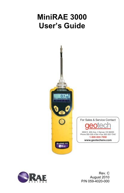
Mini<strong>RAE</strong> <strong>3000</strong>User’s <strong>Guide</strong>Rev. CAugust 2010P/N 059-4020-000
FCC InformationContains FCC ID: PI4411BThe enclosed device complies with part 15 of the FCC rules.Operation is subject to the following conditions: (1) This device maynot cause harmful interference, and (2) This device must accept anyinterference received, including interference that may cause undesiredoperation.© Copyright 2010 <strong>RAE</strong> Systems, Inc.
Mini<strong>RAE</strong> <strong>3000</strong> User’s <strong>Guide</strong>Optional Accessories.................................................................. 34Calibration Adapter................................................................ 34Calibration Regulator............................................................. 34Organic Vapor Zeroing Kit.................................................... 34Standard Two-Point Calibration (Zero & Span) ........................ 35Entering Calibration............................................................... 36Zero (Fresh Air) Calibration .................................................. 37Span Calibration..................................................................... 39Exiting Two-Point Calibration In Basic User Level .............. 41Three-Point Calibration.............................................................. 42Span 2 Calibration ............................................................. 44Exiting Three-Point Calibration......................................... 46Programming Mode.................................................................... 46Entering Programming Mode................................................. 46Programming Mode Menus........................................................ 48Zero Calibration................................................................... 49Span Calibration................................................................... 49Measurement.......................................................................... 52Meas. Gas .......................................................................... 52Meas. Unit ......................................................................... 53Alarm Setting ......................................................................... 54High Alarm........................................................................ 55Low Alarm......................................................................... 55STEL Alarm ...................................................................... 56TWA Alarm....................................................................... 57Alarm Type........................................................................ 58Buzzer & Light .................................................................. 59Datalog................................................................................... 59Clear Datalog..................................................................... 60Interval. .............................................................................. 60Data Selection.................................................................... 61Datalog Type ..................................................................... 62Manual Datalog ................................................................. 62Snapshot Datalog............................................................... 63Monitor Setup ........................................................................ 64Op Mode............................................................................ 64Site ID................................................................................ 65User ID .............................................................................. 662
Mini<strong>RAE</strong> <strong>3000</strong> User’s <strong>Guide</strong>User Mode ......................................................................... 66Basic ............................................................................. 66Advanced ...................................................................... 66Date.................................................................................... 67Time................................................................................... 67Duty Cycle......................................................................... 68Temperature Unit............................................................... 69Pump Speed ....................................................................... 69Language ........................................................................... 70Radio Power ...................................................................... 70Real Time Protocol............................................................ 71Power On Zero................................................................... 71Unit ID............................................................................... 72LCD Contrast..................................................................... 72Hygiene Mode ............................................................................ 73Advanced User Level (Hygiene Mode Or Search Mode) .......... 78Advanced User Level & Hygiene Mode................................ 78Basic User Level & Search Mode.......................................... 80Advanced User Level & Search Mode................................... 82Diagnostic Mode.................................................................... 83Entering Diagnostic Mode................................................. 83Adjusting The Pump Stall Threshold ................................ 84Pump High......................................................................... 84Pump Low.......................................................................... 84Exiting Diagnostic Mode................................................... 85Transferring Data To & From A Computer ............................... 86Downloading The Datalog To A PC...................................... 86Maintenance ............................................................................... 88Battery Charging & Replacement .......................................... 88Replacing The Li-ion Battery ............................................ 89Replacing The Alkaline Battery Adapter........................... 89PID Sensor & Lamp Cleaning/Replacement.......................... 91Sensor Components.................................................................... 91Cleaning The Lamp Housing Or Changing The Lamp...... 92Determining The Lamp Type ............................................ 93Sampling Pump.................................................................. 94Cleaning The Instrument ................................................... 94Ordering Replacement Parts.............................................. 94Special Servicing Note........................................................... 953
Mini<strong>RAE</strong> <strong>3000</strong> User’s <strong>Guide</strong>Troubleshooting.......................................................................... 96Technical Support....................................................................... 97<strong>RAE</strong> Systems Contacts............................................................... 98Controlled Part of Manual........................................................ 1014
Mini<strong>RAE</strong> <strong>3000</strong> User’s <strong>Guide</strong>Read Before OperatingThis manual must be carefully read by all individuals who have or willhave the responsibility of using, maintaining, or servicing this product.The product will perform as designed only if it is used, maintained, andserviced in accordance with the manufacturer’s instructions. The usershould understand how to set the correct parameters and interpret theobtained results.CAUTION!To reduce the risk of electric shock, turn the power off before removingthe instrument cover. Disconnect the battery before removing sensormodule for service. Never operate the instrument when the cover isremoved. Remove instrument cover and sensor module only in an areaknown to be non-hazardous.5
Mini<strong>RAE</strong> <strong>3000</strong> User’s <strong>Guide</strong>Special NotesWhen the instrument is taken out of the transport case andturned on for the first time, there may be some residual organicor inorganic vapor trapped inside the detector chamber. Theinitial PID sensor reading may indicate a few ppm. Enter an areaknown to be free of any organic vapor and turn on theinstrument. After running for several minutes, the residual vaporin the detector chamber will be cleared and the reading shouldreturn to zero.The battery of the instrument discharges slowly even if it isturned off. If the instrument has not been charged for 5 to 7days, the battery voltage will be low. Therefore, it is a goodpractice to always charge the instrument before using it. It isalso recommended to fully charge the instrument for at least 10hours before first use. Refer to this User <strong>Guide</strong>’s section onbattery charging for more information on battery charging andreplacement.6
Mini<strong>RAE</strong> <strong>3000</strong> User’s <strong>Guide</strong>WARNINGSSTATIC HAZARD: Clean only with damp cloth.For safety reasons, this equipment must be operated and servicedby qualified personnel only. Read and understand instructionmanual completely before operating or servicing.Use only <strong>RAE</strong> Systems battery packs, part numbers 059-3051-000,059-3052-000, and 059-3054-000. This instrument has not been testedin an explosive gas/air atmosphere having an oxygen concentrationgreater than 21%. Substitution of components may impair intrinsicsafety. Recharge batteries only in non-hazardous locations.Do not mix old and new batteries or batteries from differentmanufacturers.The calibration of all newly purchased <strong>RAE</strong> Systems instrumentsshould be tested by exposing the sensor(s) to known concentrationcalibration gas before the instrument is put into service.For maximum safety, the accuracy of the instrument should be checkedby exposing it to a known concentration calibration gas before eachday’s use.Do not use USB/PC communication in hazardous locations.7
Mini<strong>RAE</strong> <strong>3000</strong> User’s <strong>Guide</strong>AVERTISSEMENTDANGER RISQUE D'ORIGINE ELECTROSTATIQUE: Nettoyeruniquement avec un chiffon humide.Pour des raisons de sécurité, cet équipment doit être utilisé, entretenu etréparé uniquement par un personnel qualifié. Étudier le manueld’instructions en entier avant d’utiliser, d’entretenir ou de réparerl’équipement.Utiliser seulement l'ensemble de batterie <strong>RAE</strong> Systems, la reference059-3051-000 au 059-3052-000 au 059-3054-000. Cet instrument n’apas été essayé dans une atmosphère de gaz/air explosive ayant uneconcentration d’oxygène plus élevée que 21%. La substitution decomposants peut compromettre la sécurité intrinsique. Ne charger lesbatteries que dans emplacements désignés non-dangereuse.Ne pas melanger les anciennes et les nouvelles batteries, ou bien encoreles batteries de differents fabriquants.La calibration de toute instruments de <strong>RAE</strong> Systems doivent être testéen exposant l’instrument a une concentration de gaz connue par uneprocédure diétalonnage avant de mettre en service l’instrument pour lapremière fois.Pour une securite maximale, la sensibilité du l’instrument doit êtreverifier en exposant l’instrument a une concentration de gaz connue parune procédure diétalonnage avant chaque utilisation journalière.Ne pas utiliser de connection USB/PC en zone dangereuse.8
Mini<strong>RAE</strong> <strong>3000</strong> User’s <strong>Guide</strong>Standard ContentsInstrumentCalibration KitCharging CradleAC/DC AdapterAlkaline Battery AdapterData CableCD-ROM With User’s <strong>Guide</strong>, Quick Start <strong>Guide</strong>, and related materialsGeneral InformationThe compact instrument is designed as a broadband VOC gas monitorand datalogger for work in hazardous environments. It monitorsVolatile Organic Compounds (VOC) using a photoionization detector(PID) with a 9.8 eV, 10.6 eV, or 11.7 eV gas-discharge lamp. Featuresare:Lightweight and Compact• Compact, lightweight, rugged design• Built-in sample draw pumpDependable and Accurate• Up to 16 hours of continuous monitoring with rechargeablebattery pack• Designed to continuously monitor VOC vapor at parts-permillion(ppm) levelsUser-friendly• Preset alarm thresholds for STEL, TWA, low- and high-levelpeak values.• Audio buzzer and flashing LED display are activated when thelimits are exceeded.Datalogging Capabilities• 260,000-point datalogging storage capacity for data download to PC9
Mini<strong>RAE</strong> <strong>3000</strong> User’s <strong>Guide</strong>The instrument consists of a PID with associated microcomputer andelectronic circuit. The unit is housed in a rugged case with a backlitLCD and 3 keys to provide easy user interface. It also has a built-inflashlight for operational ease in dark locations.10
Mini<strong>RAE</strong> <strong>3000</strong> User’s <strong>Guide</strong>Physical DescriptionThe main components of the portable VOC monitoringinstrument include:• Three keys for user to interact with the instrument: 3operation/programming keys for normal operation orprogramming• LCD display with back light for direct readout and calculatedmeasurements• Built-in flashlight for illuminating testing points in darkenvironments• Buzzer and red LEDs for alarm signaling whenever exposuresexceed preset limits• Charge contacts for plugging directly to its charging station• Gas entry and exit ports• USB communication port for PC interface• Protective rubber coverSpecificationsSize:Weight:Detector:Battery:Battery Charging:Operating Hours:Display:9.25" L x 3.6" W x 2.9" H28 oz with battery packPhotoionization sensor with 9.8, 10.6, or11.7 eV UV lampA 3.7V rechargeable Lithium-Ion battery pack(snap in, field replaceable, at non-hazardouslocation only)Alkaline battery holder (for 4 AA batteries)Less than 8 hours to full chargeUp to16 hours continuous operationLarge dot matrix screen with backlight11
Measurement range & resolutionMini<strong>RAE</strong> <strong>3000</strong> User’s <strong>Guide</strong>Lamp Range Resolution10.6 eV 0.1 ppm to 15,000 ppm 0.1 ppm9.8 eV 0.1 ppm to 5,000 ppm 0.1 ppm11.7 eV 0.1 ppm to 2,000 ppm 0.1 ppmResponse time (T 90 ):Accuracy(Isobutylene):PID Detector:Correction Factors:Calibration:Calibration Reference:Inlet Probe:Radio module:2 seconds10 to 2000 ppm: ±3% at calibration point.Easy access to lamp and sensor for cleaningand replacementOver 200 VOC gases built in (based on <strong>RAE</strong>Systems Technical Note TN-106)Two-point field calibration of zero andstandard reference gasesStore up to 8 sets of calibration data, alarmlimits and span valuesFlexible 5" tubingBluetooth (2.4GHz), RF module (433MHz,868MHz , 915MHz, or 2.4GHz)Keypad: 1 operation key and 2 programming keys; 1flashlight switchDirect Readout: Instantaneous, average, STEL, TWA and peakvalue, and battery voltageIntrinsic Safety: US and Canada: Class I, Division 1, Groups A,B, C, DEurope: ATEX (0575 Ex II 2G Ex iaIIC/IIB T4 Gb)KEMA 07 ATEX 0127Complies with EN60079-0:2009,EN60079-11:200712
Mini<strong>RAE</strong> <strong>3000</strong> User’s <strong>Guide</strong>IECEx CSA 10.0005 Ex ia IIC/IIB T4 GbComplies with IEC 60079-0:2007,IEC 60079-11:2006(IIC: 059-3051-000 Li-ion bat packor 059-3054-000 NiMH bat pack;IIB: 059-3052-000 alkaline bat pack)EM Interference: Highly resistant to EMI/RFI. Compliant withEMC R&TTE (RF Modules)Alarm Setting: Separate alarm limit settings for Low, High,STEL and TWA alarmOperating Mode: Hygiene or Search modeAlarm:Buzzer 95dB at 30cm and flashing red LEDsto indicate exceeded preset limits, low batteryvoltage, or sensor failureAlarm Type: Latching or automatic resetReal-time Clock: Automatic date and time stamps on dataloggedinformationDatalogging: 260,000 points with time stamp, serial number,user ID, site ID, etc.Communication: Upload data to PC and download instrumentsetup from PC via USB on charging station.Sampling Pump: Internally integrated. Flow rate: 450 to 550cc/min.Temperature: -20º C to 50º C (-4º to 122º F)Humidity:0% to 95% relative humidity (non-condensing)Housing (including Polycarbonate, splashproof and dustproofrubber boot): Battery can be changed without removingrubber boot.13
Mini<strong>RAE</strong> <strong>3000</strong> User’s <strong>Guide</strong>Charging The BatteryAlways fully charge the battery before using the instrument. Theinstrument’s Li-ion battery is charged by placing the instrument in itscradle. Contacts on the bottom of the instrument meet the cradle’scontacts, transferring power without other connections.Note: Before setting the instrument into its charging cradle, visuallyinspect the contacts to make sure they are clean. If they are not, wipethem with a soft cloth. Do not use solvents or cleaners.Follow this procedure to charge the instrument:1. Plug the AC/DC adapter’s barrel connector into the instrument’scradle.2. Plug the AC/DC adapter into the wall outlet.3. Place the instrument into the cradle, press down, and lean itback. It locks in place and the LED in the cradle glowThe instrument begins charging automatically. The “Primary” LED inthe cradle blinks green to indicate charging. During charging, thediagonal lines in the battery icon on the instrument’s display areanimated and you see the message “Charging...”When the instrument’s battery is fully charged, the battery iconis no longer animated and shows a full battery. The message“Fully charged!” is shown. The cradle’s LED glowscontinuously green.Note: If you see the “Battery Charging Error” icon (a batteryoutline with an exclamation mark inside), check that theinstrument or rechargeable battery has been set into the cradle14
Mini<strong>RAE</strong> <strong>3000</strong> User’s <strong>Guide</strong>properly. If you still receive the message, check the Troubleshootingsection of this guide.Note: If the instrument or battery has been in the cradle for more than10 hours and you see the “Battery Charging Error” icon and a messagethat says, “Charging Too Long,” this indicates that the battery is notreaching a full charge. Try changing the battery and make sure thecontacts between the instrument (or battery) are meeting the cradle. Ifthe message is still shown, consult your distributor or <strong>RAE</strong> SystemsTechnical Services.Charging A Spare Rechargeable BatteryA rechargeable Li-ion battery can be charged when it is not inside themonitor. The charging cradle is designed to accommodate both types ofcharging. Contacts on the bottom of the battery meet the contacts on thecradle, transferring power without other connections, and a springloadedcapture holds the battery in place during charging.1. Plug the AC/DC adapter into the monitor’s cradle.2. Place the battery into the cradle, with the gold-plated contactson top of the six matching charging pins.3. Plug the AC/DC adapter into the wall outlet.The battery begins charging automatically. During charging, theSecondary LED in the cradle blinks green. When charging is complete,it glows steady green.Release the battery from the cradle by pulling it back toward the rear ofthe cradle and tilting it out of its slot.Note: If you need to replace the Li-ion battery pack, replacements areavailable from <strong>RAE</strong> Systems. The part number is 059-3051-000.Note: An Alkaline Battery Adapter (part number 059-3052-000), which usesfour AA alkaline batteries (Duracell MN1500), may be substituted for the Li-Ion battery.15
Mini<strong>RAE</strong> <strong>3000</strong> User’s <strong>Guide</strong>WARNING!To reduce the risk of ignition of hazardous atmospheres, rechargeand replace batteries only in areas known to be non-hazardous.Remove and replace batteries only in areas known to be nonhazardous.Low Voltage WarningWhen the battery’s charge falls below a preset voltage, theinstrument warns you by beeping once and flashing once everyminute, and the “empty battery” icon blinks on and off onceper second. You should turn off the instrument within 10minutes and either recharge the battery by placing theinstrument in its cradle, or replace the battery with a fresh onewith a full charge.Clock BatteryAn internal clock battery is mounted on one of the instrument’s printedcircuit boards. This long-life battery keeps settings in memory frombeing lost whenever the Li-ion battery or alkaline batteries areremoved. This backup battery should last approximately five years, andmust be replaced by an authorized <strong>RAE</strong> Systems service technician. Itis not user-replaceable.Data Protection While Power Is OffWhen the instrument is turned off, all the current real-time dataincluding last measured values are erased. However, the datalog data ispreserved in non-volatile memory. Even if the battery is disconnected,the datalog data will not be lost.16
Mini<strong>RAE</strong> <strong>3000</strong> User’s <strong>Guide</strong>User InterfaceThe instrument’s user interface consists of the display, LEDs, analarm transducer, and four keys. The keys are:Y/+MODEN/-Flashlight on/offThe LCD display provides visual feedback that includes the reading,time, battery condition, and other functions.DisplayLEDs and flashlightY/+ keyN/- keyMODE keyFlashlighton/off keyIn addition to their labeled functions, the keys labeled Y/+, MODE, andN/- act as “soft keys” that control different parameters and makedifferent selections within the instrument’s menus. From menu to17
Mini<strong>RAE</strong> <strong>3000</strong> User’s <strong>Guide</strong>menu, each key controls a different parameter or makes a differentselection.Three panes along the bottom of the display are “mapped” to the keys.These change as menus change, but at all times the left panecorresponds to the [Y/+] key, the center pane corresponds to the[MODE] key, and the right pane corresponds to the [N/-] key. Here arethree examples of different menus with the relationships of the keysclearly shown:18
Mini<strong>RAE</strong> <strong>3000</strong> User’s <strong>Guide</strong>DisplayThe display shows the following information:GraphGas infoReadingCalibration neededRadio powerRadio signalBatteryPumpDatalogY/+MODEN/-Graphic representation of concentration plottedover timeTells the Correction Factor and type ofcalibration gasConcentration of gas as measured by theinstrumentIndicates that calibration should be performedIndicates whether radio connection is on oroffIndicates signal strength in 5-bar bargraphIndicates battery level in 3 barsIndicates that pump is workingIndicates whether datalog is on or offY/+ key’s function for this screenMODE key’s function for this screenN/- key’s function for this screen19
Mini<strong>RAE</strong> <strong>3000</strong> User’s <strong>Guide</strong>Operating The InstrumentThe instrument is designed as a broadband VOC gas monitor anddatalogger for work in hazardous environments. It gives real-timemeasurements and activates alarm signals whenever the exposureexceeds preset limits. Prior to factory shipment, the instrument is presetwith default alarm limits and the sensor is pre-calibrated with standardcalibration gas. However, you should test the instrument and verify thecalibration before the first use. After the instrument is fully charged andcalibrated, it is ready for immediate operation.Turning The Instrument On1. With the instrument turned off, press and hold [MODE].2. When the display turns on, release the [MODE] key.The <strong>RAE</strong> Systems logo should appear first. (If the logo does notappear, there is likely a problem and you should contact yourdistributor or <strong>RAE</strong> Systems Technical Support.) The instrument is nowoperating and performs self tests. If any tests (including sensor andmemory tests fail), refer to the Troubleshooting section of this guide.Once the startup procedure is complete, the instrument shows anumerical reading screen with icons. This indicates that the instrumentis fully functional and ready to use.20
Mini<strong>RAE</strong> <strong>3000</strong> User’s <strong>Guide</strong>Turning The Instrument Off1. Press and hold the Mode key for 3 seconds. A 5-secondcountdown to shutoff begins.2. Once the countdown stops, the instrument is off. Release theMode key.3. When you see “Unit off...” release your finger from the[MODE] key. The instrument is now off.Note: You must hold your finger on the key for the entire shutoffprocess. If you remove your finger from the key during the countdown,the shutoff operation is canceled and the instrument continues normaloperation.Operating The Built-In FlashlightThe instrument has a built-in flashlight that helps you point the probe indark places. Press the flashlight key to turn it on. Press it again to turnit off.Note: Using the flashlight for extended periods shortens the battery’soperating time before it needs recharging.Pump StatusIMPORTANT!During operation, make sure the probe inlet and the gas outlet are freeof obstructions. Obstructions can cause premature wear on the pump,false readings, or pump stalling. During normal operation, the pumpicon alternately shows inflow and outflow as shown here:21
Mini<strong>RAE</strong> <strong>3000</strong> User’s <strong>Guide</strong>During duty cycling (PID lamp cleaning), the display shows these iconsin alternation:If there is a pump failure or obstruction that disrupts the pump, you willsee this icon blinking on and off:If you see this blinking icon, consult the Troubleshooting section of thisguide.Calibration StatusThe instrument displays this icon if it requires calibration:Calibration is required (and indicated by this icon) if:• The lamp type has been changed (for example, from 10.6 eV to9.8 eV).• The sensor has been replaced.• It has been 30 days or more since the instrument was lastcalibrated.• If you have changed the calibration gas type withoutrecalibrating the instrument.22
Mini<strong>RAE</strong> <strong>3000</strong> User’s <strong>Guide</strong>Operating ModesYour instrument operates in different modes, depending on the modeland its factory default settings. In some cases, you can change modesusing a password and using the instrument’s navigation. In other cases,you must use Pro<strong>RAE</strong> Studio software.The default setting for your instrument is:User Mode: BasicOperation Mode: HygieneThis is outlined in detail on page 74.The other options, covered later in this guide, are:User Mode: Advanced (page 78)Operation Mode: HygieneUser Mode: Advanced (page 82)Operation Mode: SearchUsing Pro<strong>RAE</strong> Studio allows access to other options. In addition,Diagnostic Mode (page 83) is available for service technicians.23
Mini<strong>RAE</strong> <strong>3000</strong> User’s <strong>Guide</strong>Basic User Level/Hygiene Mode (DefaultSettings)The instrument is programmed to operate in Basic User Level/Hygiene Mode asits default. This gives you the most commonly needed features while requiringthe fewest parameter adjustments.Pressing [N/-] steps you from one screen to the next, and eventually return to themain display. If you do not press a key within 60 seconds after entering adisplay, the instrument reverts to its main display.Note: While viewing any of these screens, you can shut off your instrument bypressing [MODE].24
Mini<strong>RAE</strong> <strong>3000</strong> User’s <strong>Guide</strong>Note: Dashed line indicates automatic progression.25
Mini<strong>RAE</strong> <strong>3000</strong> User’s <strong>Guide</strong>After the instrument is turned on, it runs through the start-up menu.Then the message “Please apply zero gas…” is displayed.At this point, you can perform a zero air (fresh air) calibration. If theambient air is clean, you can use that. Otherwise, use a cylinder of zeroair. Refer to Zero Calibration on page 37 for a more detaileddescription of zero calibration.Start zero calibration by pressing Start. You see the message“Zeroing…” followed by a 30-second countdown.Note: You can press [MODE] to quit, bypassing the zero aircalibration.When zero calibration is complete, you see the message:Zeroing is done!Reading = 0.0 ppmThe instrument is now sampling and collecting data.Note: At the Average & Peak, Date & Time & Temperature, Calibration Gas& Measurement Gas & Correction Factor, and PC Communications screens,the instrument automatically goes to the main display after 60 seconds if youdo not push a key to make a selection.Alarm SignalsDuring each measurement period, the gas concentration is comparedwith the programmed alarm limits (gas concentration alarm limitsettings). If the concentration exceeds any of the preset limits, the loudbuzzer and red flashing LED are activated immediately to warn you ofthe alarm condition.In addition, the instrument alarms if one of the following conditionsoccurs: battery voltage falls below a preset voltage level, failure of theUV lamp, or pump stall.26
Alarm Signal SummaryMini<strong>RAE</strong> <strong>3000</strong> User’s <strong>Guide</strong>Message Condition Alarm SignalHIGHOVRMAXLOWTWASTELPumpiconflashesGas exceeds “HighAlarm” limitGas exceedsmeasurement rangeGas exceeds electronics’maximum rangeGas exceeds “LowAlarm” limitGas exceeds “TWA”limitGas exceeds “STEL”limitPump failure3 beeps/flashes per second*3 beeps/flashes per second*3 beeps/flashes per second*2 beeps/flashes per second*1 Beep/flash per second*1 Beep/flash per second*3 beeps/flashes per secondLamp PID lamp failure 3 beeps/flashes per secondplus “Lamp” message ondisplayBatteryiconflashesCALNEGLow batteryCalibration failed, orneeds calibrationGas reading measuresless than number stored incalibration1 flash, 1 beep per minuteplus battery icon flashes ondisplay1 beep/flash per second1 beep/flash per second* Hygiene mode only. In Search mode, the number of beeps per second(1 to 7) depends upon the concentration of the sampled gas. Faster ratesindicate higher concentrations.27
Mini<strong>RAE</strong> <strong>3000</strong> User’s <strong>Guide</strong>Preset Alarm Limits & CalibrationThe instrument is factory calibrated with standard calibration gas, andis programmed with default alarm limits.Cal Gas(Isobutylene)Mini<strong>RAE</strong><strong>3000</strong>CalSpanunit Low High TWA STEL100 ppm 50 100 10 25Testing The AlarmYou can test the alarm whenever the main (Reading) display is shown.Press [Y/+], and the audible and visible alarms are tested.Integrated Sampling PumpThe instrument includes an integrated sampling pump. This diaphragmtypepump that provides a 450 to 550 cc per minute flow rate.Connecting a Teflon or metal tubing with 1/8" inside diameter to thegas inlet port of the instrument, this pump can pull in air samples from100' (30 m) away horizontally or vertically.Note: In Search Mode, the pump turns on when a sample measurementis started, and turns off when the sample is manually stopped.If liquid or other objects are pulled into the inlet port filter, theinstrument detects the obstruction and immediately shuts down thepump. The alarm is activated and a flashing pump icon is displayed.You should acknowledge the pump shutoff condition by clearing theobstruction and pressing the [Y/+] key while in the main readingdisplay to restart the pump.28
Mini<strong>RAE</strong> <strong>3000</strong> User’s <strong>Guide</strong>BacklightThe LCD display is equipped with an LED backlight to assist inreading the display under poor lighting conditions.DataloggingDuring datalogging, the instrument displays a disk icon to indicate thatdatalogging is enabled. The instrument stores the measured gasconcentration at the end of every sample period (when data logging isenabled). In addition, the following information is stored: user ID, siteID, serial number, last calibration date, and alarm limits. All data areretained (even after the unit is turned off) in non-volatile memory sothat it can be down- loaded at a later time to a PC.Datalogging eventWhen Datalogging is enabled, measurement readings are being saved.These data are stored in “groups” or “events.” A new event is createdand stored each time the instrument is turned on and is set to automaticdatalogging, or a configuration parameter is changed, or datalogging isinterrupted. The maximum time for one event is 24 hours or 28,800points. If an event exceeds 24 hours, a new event is automaticallycreated. Information, such as start time, user ID, site ID, gas name,serial number, last calibration date, and alarm limits are recorded.Datalogging sampleAfter an event is recorded, the unit records a shorter form of the data.When transferred to a PC running Pro<strong>RAE</strong> Studio, this data is arrangedwith a sample number, time, date, gas concentration, and other relatedinformation.29
Mini<strong>RAE</strong> <strong>3000</strong> User’s <strong>Guide</strong>Auto/Manual/Snapshot DataloggingThe instrument has three datalog types:AutoManualSnapshotDefault mode. Collects datalog information when theinstrument is sampling.Datalogging occurs only when the instrument’sdatalogging is manually started (see page 63 fordetails).Datalogs only during snapshot (single-event capture,initiated by pressing [MODE]) sampling. See page 65for details.Note: You can only choose one datalog type to be active at a time.30
Mini<strong>RAE</strong> <strong>3000</strong> User’s <strong>Guide</strong>AccessoriesThe following accessories are included with the instrument:• An AC Adapter (Battery Charger)• Alkaline battery adapter• External Filter• Organic Vapor Zeroing kitHard-case kits also include these accessories:• Calibration adapter• Calibration regulator and Flow controllerStandard Kit & AccessoriesAC Adapter (Battery Charger)WARNINGTo reduce the risk of ignition of hazardous atmospheres, rechargebattery only in area known to be non-hazardous. Remove andreplace battery only in area known to be non-hazardous.Ne charger les batteries que dans emplacements designés nondangereuses.A battery charging circuit is built into the instrument cradle. It only needs aregular AC to 12 VDC adapter (wall-mount transformer, part number 500-0114-000) to charge the instrument.To charge the battery inside the instrument:1. Power off the instrument.2. Connect the AC adapter to the DC jack on the instrument’s cradle. Ifthe instrument is off, it automatically turns on.3. While charging, the display message shows “Charging.” ThePrimary LED on the cradle flashes green when charging.4. When the battery is fully charged, the LED changes to glowing greencontinuously, and the message “Fully charged” appears on the31
Mini<strong>RAE</strong> <strong>3000</strong> User’s <strong>Guide</strong>display. If there is a charging error, the LED glows redcontinuously.A completely discharged instrument can be charged to full capacitywithin 8 hours. Batteries drain slowly even if an instrument is off.Therefore, if the instrument has been in storage or has not been chargedfor several days or longer, check the charge before using it.The factory-supplied battery is designed to last for 16 hours of normaloperation (no alarm), for a new battery under the optimumcircumstances. As the battery becomes older or is subject to adverseconditions (such as cold ambient temperature), its capacity will besignificantly reduced.Alkaline Battery AdapterAn alkaline battery adapter is supplied with each instrument. Theadapter (part number 059-3052-000) accepts four AA alkaline batteries(use only Duracell MN1500) and provides approximately 12 hours ofoperation. The adapter is intended to be used in emergency situationswhen there is no time to charge the Li-ion battery pack.To insert batteries into the adapter:1. Remove the three Philips-head screws toopen the compartment in the adapter.2. Insert four fresh AA batteries as indicatedby the polarity (+/-) markings.3. Replace the cover. Replace the threescrews.To install the adapter in the instrument:1. Remove the Li-ion battery pack from the instrument by slidingthe tab and tilting out the battery.2. Replace it with the alkaline battery adapter3. Slide the tab back into place to secure the battery adapter.IMPORTANT!Alkaline batteries cannot be recharged. The instrument’s internal circuitdetects alkaline batteries and will not allow recharging. If you place theinstrument in its cradle, the alkaline battery will not be recharged. The32
Mini<strong>RAE</strong> <strong>3000</strong> User’s <strong>Guide</strong>internal charging circuit is designed to prevent damage to alkalinebatteries and the charging circuit when alkaline batteries are installedinside the instrument. If you try to charge an alkaline batteries installedin the instrument, the instrument’s display will say, “Alkaline Battery,”indicating that it will not charge the alkaline batteries.Note: When replacing alkaline batteries, dispose of old ones properly.WARNING!To reduce the risk of ignition of hazardous atmospheres, recharge thebattery only in areas known to be non-hazardous. Remove and replacethe battery only in areas known to be non-hazardous.External FilterThe external filter is made of PTFE (Teflon ® ) membrane with a 0.45micron pore size to prevent dust or other particles from being suckedinto the sensor manifold, which would cause extensive damage to theinstrument. It prolongs the operating life of the sensor. To install theexternal filter, simply connect it to the instrument’s inlet tube.33
Mini<strong>RAE</strong> <strong>3000</strong> User’s <strong>Guide</strong>Optional AccessoriesCalibration AdapterThe calibration adapter for the instrument is a simple 6-inch Tygontubing with a metal adapter on one end. During calibration, simplyinsert the metal adapter into the regular gas inlet probe of theinstrument and the tubing to the gas regulator on the gas bottle.Calibration RegulatorThe Calibration Regulator is used in the calibration process. It regulatesthe gas flow rate from the Span gas cylinder into the gas inlet of theinstrument during calibration process. The maximum flow rate allowedby the flow controller is about 0.5L/min (500 cc per min.).Alternatively, a demand-flow regulator or a Tedlar gas bag may beused to match the pump flow precisely.Organic Vapor Zeroing KitThe Organic Vapor Zeroing Kit is used for filtering organic aircontaminants that may affect the zero calibration reading. To use theOrganic Vapor Zeroing Kit, simply connect the filter to the inlet port ofthe instrument.34
Mini<strong>RAE</strong> <strong>3000</strong> User’s <strong>Guide</strong>Standard Two-Point Calibration (Zero &Span)The following diagram shows the instrument’s calibrations inBasic/Hygiene mode.Note: Dashed line indicates automatic progression.35
Entering CalibrationMini<strong>RAE</strong> <strong>3000</strong> User’s <strong>Guide</strong>1. Press and hold [MODE] and [N/-] until you see the Passwordscreen.2. In Basic User Level, you do not need a password to performcalibrations. Instead of inputting a password, enter calibrationby pressing [MODE].Note: If you inadvertently press [Y/+] and change any of thenumbers, simply press [MODE] and you will be directed to thecalibration menu.The Calibration screen is now visible with Zero Calibrationhighlighted.These are your options:• Press [Y/+] to select the highlighted calibration (Zero Calib orSpan Calib).• Press [MODE] to exit calibration and return to the main displayand resume measurement.• Press [N/-] to toggle the highlighted calibration type.36
Mini<strong>RAE</strong> <strong>3000</strong> User’s <strong>Guide</strong>Zero (Fresh Air) CalibrationThis procedure determines the zero point of the sensor calibrationcurve. To perform a fresh air calibration, use the calibration adapter toconnect the instrument to a “fresh” air source such as from a cylinder orTedlar bag (optional accessory). The “fresh” air is clean, dry airwithout organic impurities and an oxygen value of 20.9%. If such anair cylinder is not available, any clean ambient air without detectablecontaminants or a charcoal filter can be used.At the Zero Calibration menu, you can proceed to perform a Zerocalibration or bypass Zero calibration and perform a Span calibration.You may also go back to the initial Calibration menu if you want toexit calibration.• Press [Y/+] to start calibration.• Press [MODE] to quit and return to the main calibrationdisplay.If you have pressed [Y/+] to enter Zero calibration, then you will seethis message:1. Turn on your Zero calibration gas.2. Press [Y/+] to start calibration.Note: At this point, you may press [MODE] if you decide thatyou do not want to initiate calibration. This will take youdirectly to the Calibration menu, highlighted for Spancalibration.37
Mini<strong>RAE</strong> <strong>3000</strong> User’s <strong>Guide</strong>3. Zero calibration starts a 30-second countdown and displays thismessage:Zeroing...During the zeroing process, the instrument performs the Zerocalibration automatically and does not require any action on your part.Note: To abort the zeroing process at any time and proceed to Spancalibration, press [N/-] at any time while zeroing is being performed.You will see a confirmation message that says “Zero aborted!” and thenthe Span calibration menu appears.When Zero calibration is complete, you see this message:Zeroing is done!Reading = 0.0 ppmThe instrument will then show the Calibration menu on its display, withSpan Calib highlighted.38
Mini<strong>RAE</strong> <strong>3000</strong> User’s <strong>Guide</strong>Span CalibrationThis procedure determines the second point of the sensor calibrationcurve for the sensor. A cylinder of standard reference gas (span gas)fitted with a 500 cc/min. flow-limiting regulator or a flow-matchingregulator is the simplest way to perform this procedure. Choose the 500cc/min. regulator only if the flow rate matches or slightly exceeds theflow rate of the instrument pump. Alternatively, the span gas can firstbe filled into a Tedlar bag or delivered through a demand-flowregulator. Connect the calibration adapter to the inlet port of theinstrument, and connect the tubing to the regulator or Tedlar bag.Another alternative is to use a regulator with >500 cc/min flow butallow the excess flow to escape through a T or an open tube. In thelatter method, the span gas flows out through an open tube slightlywider than the probe, and the probe is inserted into the calibration tube.At the Span Calibration menu, you perform a Span calibration. Youmay also go back to the Zero calibration menu or to the initialCalibration menu if you want to exit calibration.• Press [Y/+] to enter Span calibration.• Press [N/-] to skip Span calibration and return to Zerocalibration.• Press [MODE] to exit Span calibration and return to the topcalibration menu.If you have pressed [Y/+] to enter Span calibration, then you will seethe name of your Span gas (the default is isobutylene) and the spanvalue in parts per million (ppm). You will also see this message thatprompts you:1. Turn on your span calibration gas.2. Press [Y/+] to initiate calibration.39
Mini<strong>RAE</strong> <strong>3000</strong> User’s <strong>Guide</strong>Note: You may press [MODE] if you decide that you do notwant to initiate calibration. This will abort the span calibrationand take you directly to the Calibration menu for Zerocalibration.3. Span calibration starts and displays this message:Calibrating...During the Span calibration process, there is a 30-second countdownand the instrument performs the Span calibration automatically. Itrequires no actions on your part.Note: If you want to abort the Span calibration process, press [N/-] atany time during the process. You will see a confirmation message thatsays “Span is aborted!” and then the Zero calibration menu appears.You can then proceed to perform a Zero calibration, perform a Spancalibration, or exit to the topmost Calibration menu.When Span calibration is complete, you see a message similar to this(the value is an example only):Span 1 is done!Reading = 100.0 ppmThe instrument then exits Span calibration and shows the Zerocalibration menu on its display.Note: The reading should be very close to the span gas value.40
Mini<strong>RAE</strong> <strong>3000</strong> User’s <strong>Guide</strong>Exiting Two-Point Calibration In Basic UserLevelWhen you are done performing calibrations, press [MODE], whichcorresponds with “Back” on the display. You will see the followingmessage:Updating settings…The instrument updates its settings and then returns to the main display.It begins or resumes monitoring.41
Mini<strong>RAE</strong> <strong>3000</strong> User’s <strong>Guide</strong>Three-Point CalibrationFor enhanced accuracy, it is possible to perform a second Spancalibration in addition to the Zero and Span calibrations outlined in theprevious section. Your instrument first must be set to allow this thirdcalibration. This requires using Pro<strong>RAE</strong> Studio software and a PC, aswell as a higher concentration of calibration gas.Note: Once the third calibration is set, you do not need to use Pro<strong>RAE</strong>Studio to allow future 3-point calibrations. Also, you can only disable3-point calibration capability by using Pro<strong>RAE</strong> Studio again.Perform the Zero and Span calibrations. After the first Span calibration(Span 1) is completed, the display a second Span calibration (Span 2)can be performed. The process is identical to the first calibration. As inthe Span 1 calibration, you may exit and return to the Zero calibrationscreen if you choose not to perform this calibration or to abort it.42
Mini<strong>RAE</strong> <strong>3000</strong> User’s <strong>Guide</strong>Note: Dashed line indicates automatic progression.43
Mini<strong>RAE</strong> <strong>3000</strong> User’s <strong>Guide</strong>Span 2 CalibrationA cylinder of standard reference gas (span gas) fitted with a 500cc/min. flow-limiting regulator or a flow-matching regulator is thesimplest way to perform this procedure.Note: This gas should be of a higher concentration than the gas usedfor Span 1 calibration.Choose the 500 cc/min. regulator only if the flow rate matches orslightly exceeds the flow rate of the instrument pump. Alternatively,the span gas can first be filled into a Tedlar bag or delivered through ademand-flow regulator. Connect the calibration adapter to the inlet portof the instrument, and connect the tubing to the regulator or Tedlar bag.Another alternative is to use a regulator with >500 cc/min flow butallow the excess flow to escape through a T or an open tube. In thelatter method, the span gas flows out through an open tube slightlywider than the probe, and the probe is inserted into the calibration tube.At the Span Calibration menu, you perform a Span calibration. Youmay also go back to the Zero calibration menu or to the initialCalibration menu if you want to exit calibration.• Press [Y/+] to enter Span 2 calibration.• Press [N/-] to skip Span calibration and return to Zerocalibration.• Press [MODE] to exit Span calibration and return to the topcalibration menu.If you have pressed [Y/+] to enter Span calibration, then you will seethe name of your Span gas (the default is isobutylene) and the spanvalue in parts per million (ppm). You will also see this message thatprompts you:Please apply gas...4. Turn on your span calibration gas.5. Press [Y/+] to initiate calibration.44
Mini<strong>RAE</strong> <strong>3000</strong> User’s <strong>Guide</strong>Note: You may press [MODE] if you decide that you do notwant to initiate calibration. This will take you directly to theCalibration menu for Zero calibration.6. Span calibration starts a 30-second countdown and displaysthis message:Calibrating...During the Span calibration process, the instrument performs the Spancalibration automatically and does not require any action on your part.Note: If you want to abort the Span calibration process, press [N/-] atany time during the process. You will see a confirmation message thatsays “Span is aborted!” and then the Zero calibration menu will appear.You can then proceed to perform a Zero calibration, perform a Spancalibration, or exit to the topmost Calibration menu.When Span calibration is complete, you will see a message similar tothis (the value shown here is for example only):Span 2 is done!Reading = 1000 ppmThe instrument then exits Span calibration and shows the Zerocalibration menu on its display.Note: The reading should be very close to the span gas value.45
Mini<strong>RAE</strong> <strong>3000</strong> User’s <strong>Guide</strong>Exiting Three-Point CalibrationWhen you are done performing calibrations, press [MODE], whichcorresponds with “Back” on the display. You will see the followingmessage:Updating settings…The instrument updates its settings and then returns to the main display.It begins or resumes monitoring.Programming ModeProgramming Mode can be entered from either Hygiene Mode orSearch Mode. If the current user mode is Basic, you must provide a 4-digit password to enter.Entering Programming Mode1. Press and hold [MODE] and [N/-] until you see the Password screen.2. Input the 4-digit password:• Increase the number from 0 through 9 by pressing [Y/+].• Step from digit to digit using [N/-].• Press [MODE] when you are done.If you make a mistake, you can cycle through the digits by pressing[N/-] and then using [Y/+] to change the number in each position.46
Mini<strong>RAE</strong> <strong>3000</strong> User’s <strong>Guide</strong>Note: The default password is 0000.When you have successfully entered Programming Mode, you see thisscreen:Note: The password can only be changed by connecting the instrumentto a PC running Pro<strong>RAE</strong> Studio software. Follow the instructions inPro<strong>RAE</strong> Studio to change it.47
Mini<strong>RAE</strong> <strong>3000</strong> User’s <strong>Guide</strong>The Calibration label is shown and its icon is highlighted, but you canpress [N/-] to step from one programming menu to the next, with thename of the menu shown at the top of the display and thecorresponding icon highlighted. As you repeatedly press [N/-], theselection moves from left to right, and you see these screens:Note: When you reach Monitor Setup and press [N/-], the menu cyclesback to Calibration.Programming Mode MenusThe Programming Mode allows anyone with the password to changethe instrument’s settings, calibrate the instrument, modify the sensorconfiguration, enter user information, etc. Programming Mode has fivemenus. Each menu includes several sub-menus to perform additionalprogramming functions.This table shows the menus and sub-menus:48
Mini<strong>RAE</strong> <strong>3000</strong> User’s <strong>Guide</strong>Calibration Measurement AlarmSettingZero Meas. Gas HighCalibrationAlarmSpan Meas. Unit LowCalibrationAlarmSTELAlarmTWAAlarmAlarmTypeBuzzer& LightDatalogClearDatalogIntervalDataSelectionDatalogTypeMonitorSetupOp ModeSite IDUser IDUser ModeDateTimePump DutyCyclePump SpeedTemperatureUnitLanguageRadioPowerReal TimeProtocolPower OnZeroUnit IDLCDContrast49
Mini<strong>RAE</strong> <strong>3000</strong> User’s <strong>Guide</strong>Once you enter Programming Mode, the LCD displays the first menu,Calibration. Each subsequent menu is accessed by pressing [N/-]repeatedly until the desired menu is displayed. To enter a sub-menu ofa menu, press [Y/+].Exiting Programming ModeTo exit Programming Mode and return to normal operation, press[MODE] once at any of the programming menu displays. You will see“Updating Settings…” as changes are registered and the mode changes.Navigating Programming Mode MenusNavigating through the Programming Mode menus is easy andconsistent, using a single interface format of “Select,” “Back” and“Next” at the top level. The three control buttons correspond to thesechoices as shown:Note: Pressing [MODE] in the Programming Mode’s top level causesthe instrument to exit Programming Mode and return to monitoring.The three keys perform the following functions in Programming Mode:Key[MODE]:[Y/+]:[N/-]:Function in Programming ModeExit menu when pressed momentarily or exit dataentry modeIncrease alphanumerical value for data entry orconfirm (yes) for a questionProvides a “no” response to a question50
Mini<strong>RAE</strong> <strong>3000</strong> User’s <strong>Guide</strong>CalibrationTwo types of calibration are available: Zero (fresh air) and Span.Select Zero or Span Calibration by pressing [N/+]. Once your choice ishighlighted, press [Y/+].Zero CalibrationThe procedure for performing a zero calibration is covered on page 35.Span CalibrationThe procedure for performing a basic span calibration is covered onpage 35.51
MeasurementMini<strong>RAE</strong> <strong>3000</strong> User’s <strong>Guide</strong>The sub-menus for Measurement are Measurement Gas andMeasurement Unit.Meas. GasMeasurement gases are organized in four lists:• My List is a customized list of gases that you create. It contains amaximum of 10 gases and can only be built in Pro<strong>RAE</strong> Studio on aPC and transferred to the instrument. Note: The first gas in the listis always isobutylene (it cannot be removed from the list).• Last Ten is a list of the last ten gases used by your instrument. Thelist is built automatically and is only updated if the gas selectedfrom Custom Gases or Library is not already in the Last Ten. Thisensures that there is no repetition.• Gas Library is a library that consists of all the gases found in <strong>RAE</strong>Systems’ Technical Note TN-106 (available online atwww.raesystems.com).• Custom Gases are gases with user-modified parameters. UsingPro<strong>RAE</strong> Studio, all parameters defining a gas can be modified,including the name, span value(s), correction factor, and defaultalarm limits.1. Scroll through each list by pressing [N/-].2. Press [Y/+] to select one (My List, Last Ten, Gas Library, orCustom Gases).52
Mini<strong>RAE</strong> <strong>3000</strong> User’s <strong>Guide</strong>3. Once you are in one of the categories, press [N/-] to scrollthrough its list of options and [Y/+] to select one. (If you press[MODE], you exit to the next submenu.)4. Press [Y/+] to save your choice or [N/-] to undo your selection.Leave the sub-menu and return to the Programming Mode menus bypressing [MODE].Meas. UnitStandard available measurement units include:Abbreviation Unit Mini<strong>RAE</strong> <strong>3000</strong>ppm parts per million Yesppb parts per billionmg/m3 milligrams per cubic meter Yesug/m3 micrograms per cubic meter• Scroll through the list by pressing [N/-].• Select by pressing [Y/+].• Save your selection by pressing [Y/+] or undo your selection bypressing [N/-].Leave the sub-menu and return to the Programming Mode menus bypressing [MODE].53
Mini<strong>RAE</strong> <strong>3000</strong> User’s <strong>Guide</strong>Alarm SettingDuring each measurement period, the gas concentration is comparedwith the programmed alarm limits (gas concentration alarm limitsettings: Low, High, TWA and STEL). If the concentration exceeds anyof the preset limits, the loud buzzer and red flashing LED are activatedimmediately to warn of the alarm condition.An alarm signal summary is shown on page 27.In this menu, you can change the High and Low alarm limits, the STELlimit, and the TWA. Press [Y/+] to to enter the Alarm Setting menu.Note: All settings are shown in ppb (parts per billion), or µg/m 3(micrograms per cubic meter), depending on your setting.1. Scroll through the Alarm Limit sub-menu using the [N/-] keyuntil the display shows the desired limit to be changed (HighAlarm, Low Alarm, STEL Alarm, and TWA Alarm)2. Press [Y/+] to select one of the alarm types. The display showsa flashing cursor on the left-most digit of the previously storedalarm limit.3. Press [Y/+] to increase each digit’s value.4. Press [N/-] to advance to the next digit.5. Again, use [Y/+] to increase the number.Repeat this process until all numbers are entered.Press [MODE] when you are done.• Press [Y/+] to save the changes.• Press [N/-] to undo the changes and revert to the previous settings.When all alarm types have been changed or bypassed, press [MODE]to exit to the Programming Menu.54
Mini<strong>RAE</strong> <strong>3000</strong> User’s <strong>Guide</strong>High AlarmYou can change the High Alarm limit value. The value is typically setby the instrument to match the value for the current calibration gas. It isexpressed in parts per billion (ppb). Note: The default value dependson the measurement gas.To change the High Alarm value:1. Press [Y/+] to increase each digit’s value.2. Press [N/-] to advance to the next digit.3. Again, use [Y/+] to increase the number.Repeat this process until all numbers are entered.When you have completed your selections, press [MODE]. You willsee two choices: Save and Undo. You have the opportunity to registerthe new settings or to change your mind and revert to your previoussettings.Press [Y/+] to save the changes.Press [N/-] to undo the changes and revert to the previous settings.Low AlarmYou can change the Low Alarm limit value. The value is typically setby the instrument to match the value for the current calibration gas. It isexpressed in parts per billion (ppb). Note: The default value dependson the measurement gas.To change the Low Alarm value:1. Press [Y/+] to increase each digit’s value.2. Press [N/-] to advance to the next digit.3. Again, use [Y/+] to increase the number.Repeat this process until all numbers are entered.55
Mini<strong>RAE</strong> <strong>3000</strong> User’s <strong>Guide</strong>When you have completed your selections, press [MODE]. You willsee two choices: Save and Undo. You have the opportunity to registerthe new settings or to change your mind and revert to your previoussettings.• Press [Y/+] to save the changes.• Press [N/-] to undo the changes and revert to the previoussettings.STEL AlarmYou can change the STEL Alarm limit value. The value is typically setby the instrument to match the value for the calibration gas. It isexpressed in parts per billion (ppb). Note: The default value dependson the measurement gas.To change the STEL Alarm value:1. Press [Y/+] to increase each digit’s value.2. Press [N/-] to advance to the next digit.3. Again, use [Y/+] to increase the number.Repeat this process until all numbers are entered.When you have completed your selections, press [MODE]. You willsee two choices: Save and Undo. You have the opportunity to registerthe new settings or to change your mind and revert to your previoussettings.• Press [Y/+] to save the changes.• Press [N/-] to undo the changes and revert to the previoussettings.56
Mini<strong>RAE</strong> <strong>3000</strong> User’s <strong>Guide</strong>TWA AlarmYou can change the TWA (time-weighted average) Alarm limit value.The value is typically set by the instrument to match the value for thecalibration gas. It is expressed in parts per billion (ppb). Note: Thedefault value depends on the measurement gas.To change the TWA Alarm value:1. Press [Y/+] to increase each digit’s value.2. Press [N/-] to advance to the next digit.3. Again, use [Y/+] to increase the number.Repeat this process until all numbers are entered.When you have completed your selections, press [MODE]. You willsee two choices:• Save• UndoYou have the opportunity to register the new settings or to change yourmind and revert to your previous settings.• Press [Y/+] to save the changes.• Press [N/-] to undo the changes and revert to the previoussettings.57
Mini<strong>RAE</strong> <strong>3000</strong> User’s <strong>Guide</strong>Alarm TypeThere are two selectable alarm types:LatchedWhen the alarm is triggered, you canmanually stop the alarm.The latched setting only controls alarmsfor High Alarm, Low Alarm, STEL Alarm,and TWA alarm.Automatic ResetNote: To clear an alarm when theinstrument is set to “Latched,” press [Y/+]when the main (Reading) display is shown.When the alarm condition is no longerpresent, the alarm stops and resets itself.1. Press [N/-] to step from one alarm type to the other.2. Press [Y/+] to select an alarm type.When you have completed your selections, press [MODE].You will see two choices: Save and Undo. You have theopportunity to register the new settings or to change your mind andrevert to your previous settings.• Press [Y/+] to save the changes.• Press [N/-] to undo the changes and revert to the previoussettings.58
Mini<strong>RAE</strong> <strong>3000</strong> User’s <strong>Guide</strong>Buzzer & LightThe buzzer and light alarms can be programmed to be on or offindividually or in combination. Your choices are:• Both on• Light only• Buzzer only• Both off1. Press [N/-] to step from one option to the next.2. Press [Y/+] to make your selection (the dark circle in the “radiobutton” indicates your selection).3. When you have completed your selections, press [MODE].You will see two choices: Save and Undo. You have theopportunity to register the new settings or to change your mind andrevert to your previous settings.• Press [Y/+] to save the changes.• Press [N/-] to undo the changes and revert to the previoussettings.DatalogThe instrument calculates and stores the concentration and ID of eachsample taken. In the datalog sub-menu, a user can perform the tasksand functions shown below.59
Mini<strong>RAE</strong> <strong>3000</strong> User’s <strong>Guide</strong>1. Scroll through the Datalog sub-menu using the [N/-] key until thedisplay shows the desired parameter to be changed:Clear DatalogIntervalData SelectionDatalog Type2. Press [Y/+] to make your selection. Exit by pressing [MODE] forBack.Clear DatalogThis erases all the data stored in the datalog.Note: Once the datalog is cleared, the data cannot be recovered.Press [Y/+] to clear the datalog. The display asks, “Are you sure?”• Press [Y/+] if you want to clear the datalog. When it has beencleared, the display shows “Datalog Cleared!”• Press [N/-] if you do not want to clear the datalog.The display changes, and you are taken to the next sub-menu, Interval.IntervalIntervals are shown in seconds. The default value is 60 seconds. Themaximum interval is 3600 seconds.1. Press [Y/+] to increase each digit’s value.2. Press [N/-] to advance to the next digit.3. Again, use [Y/+] to increase the number.60
Mini<strong>RAE</strong> <strong>3000</strong> User’s <strong>Guide</strong>Repeat this process until all numbers are entered.When you have completed your selections, press [MODE].You will see two choices: Save and Undo. You have the opportunity toregister the new settings or to change your mind and revert to yourprevious settings.• Press [Y/+] to save the changes.• Press [N/-] to undo the changes and revert to the previoussettings.Data SelectionData Selection allows you to select which types of data are stored andmade available when you offload your datalog to a computer viaPro<strong>RAE</strong> Studio software.You can choose any or all of three types of data (you must choose atleast one):• Average• Maximum• Minimum1. Press [N/-] to step from one option to the next. The highlighterindicates your choice.2. Press [Y/+] to toggle your selection on or off (the check boxindicates “on” with an “X”).3. When you have completed your selections, press [MODE].You will see two choices: Save and Undo. You have the opportunity toregister the new settings or to change your mind and revert to yourprevious settings.• Press [Y/+] to save the changes.• Press [N/-] to undo the changes and revert to the previoussettings.61
Mini<strong>RAE</strong> <strong>3000</strong> User’s <strong>Guide</strong>Datalog TypeThe instrument has three datalog types:Auto Default mode. Collects datalog information when theinstrument is sampling.Manual Datalogging occurs only when the instrument’sdatalogging is manually started (see below for details).Snapshot Datalogs only during single-event capture sampling.Note: You can only choose one datalog type to be active at a time.1. Press [N/-] to step from one option to the next.2. Press [Y/+] to make your selection (the dark circle in the “radiobutton” indicates “on”).3. When you have completed your selection, press [MODE].You will see two choices: Save and Undo. You have the opportunity toregister the new settings or to change your mind and revert to yourprevious settings.• Press [Y/+] to save the changes.Press [N/-] to undo the changes and revert to the previous settings.Manual DatalogWhen the instrument is set to Manual Datalog, you turn datalogging onand off by stepping through the displays from the Main Display, andthen pressing the keys to select datalog on/off functions.• When you reach the screen that says “Start Datalog?” press[Y/+] to start it. You see “Datalog Started,” confirming thatdatalogging is now on.When you reach the screen that says “Stop Datalog?” press [Y/+] tostop it. You see “Datalog Stopped,” confirming that datalogging is nowoff.62
Mini<strong>RAE</strong> <strong>3000</strong> User’s <strong>Guide</strong>Note: Dashed line indicates automatic progression.63
Snapshot DatalogMini<strong>RAE</strong> <strong>3000</strong> User’s <strong>Guide</strong>When the instrument is in Snapshot datalogging mode, it captures asingle “snapshot” of the data at the moment of your choosing.Whenever the instrument is on and it is set to Snapshot, all you have todo is press [MODE] each time you want to capture a snapshot of thedata at that instant.When you send the data to a computer using Pro<strong>RAE</strong> Studio, the datasnapshots are uniquely identified by time and other parameters.Monitor SetupMany settings can be accessed in this menu, including setting the dateand time and adjusting the pump’s on/off duty cycle.Op ModeUnder Monitor Setup is “Op Mode.”Press [Y/+] to select.You see two options (one is highlighted):HygieneSearch64
Mini<strong>RAE</strong> <strong>3000</strong> User’s <strong>Guide</strong>The current mode is indicated by a dark circle within the circle in frontof either Hygiene or Search.1. Select Hygiene or Search by pressing [N/-]. The highlightingchanges from one to the other each time you press [N/-].2. Press [Y/+] to select that mode for the instrument.3. Press [MODE] when you want to register your selection toplace the instrument in the selected mode.4. Press [Y/+] to commit the change and exit to the Monitor Setupscreen, or press [N/-] to Undo (exit to the Monitor Setup screenwithout changing the Mode).Site IDEnter an 8-digit alphanumeric/character Site ID in the programmingmode. This Site ID is included in the datalog report.1. Press [Y/+] and the display shows the current site ID. Example:“<strong>RAE</strong>00001.” Note that the left-most digit flashes to indicate itis the selected one.2. Press [Y/+] to step through all 26 letters (A to Z) and 10numerals (0 to 9).Note: The last four digits must be numerals.3. Press [N/-] to advance to the next digit. The next digit to theright flashes.Repeat this process until all eight digits of the new site ID areentered.Press [MODE] to exit.If there is any change to the existing site ID, the display shows “Save?”Press [Y/+] to accept the new site ID. Press [N/-] to discard the changeand move to the next sub-menu.65
Mini<strong>RAE</strong> <strong>3000</strong> User’s <strong>Guide</strong>User IDEnter an 8-digit alphanumeric User ID in the programming mode. ThisUser ID is included in the datalog report.1. Press [Y/+] and the display shows the current User ID.Example: “<strong>RAE</strong>00001.” Note that the left-most digit flashes toindicate it is the selected one.2. Press [Y/+] to step through all 26 letters (A to Z) and 10numerals (0 to 9).3. Press [N/-] to advance to the next digit. The next digit to theright flashes.Repeat this process until all eight digits of the new User ID areentered.Press [MODE] to exit.If there is any change to the existing User ID, the display shows “Save”Press [Y/+] to accept the new site ID. Press [N/-] to discard (undo) thechange and move to the next sub-menu.User ModeThe instrument has two user modes:Basic Basic users can only see and use a basic set offunctions.Advanced Advanced users can see all screens and perform allavailable functions.Note: The default value for User Mode is Basic.66
To change the User Mode:Mini<strong>RAE</strong> <strong>3000</strong> User’s <strong>Guide</strong>1. Press [N/-] to step from one option to the next. The highlightingchanges each time you press [N/-].2. Press [Y/+] to make your selection (the dark circle in the “radiobutton” indicates “on”).3. When you have completed your selection, press [MODE].4. Press [Y/+] to accept the new User Mode. Press [N/-] to discard thechange and move to the next sub-menu.DateThe Date is expressed as Month/Day/Year, with two digits for each.1. Press [Y/+] and the display shows the current date. Note thatthe left-most digit flashes to indicate it is selected.2. Press [Y/+] to step through all 10 numerals (0 to 9).3. Press [N/-] to advance to the next digit. The next digit to theright flashes.Repeat this process until all six digits of the new date areentered.Press [MODE] to exit.• Press [Y/+] to save the new date.• Press [N/-] to undo the change and move to the next sub-menu.TimeThe Time is expressed as Hours/Minutes/Seconds, with two digits foreach. The time is in 24-hour (military) format.1. Press [Y/+] and the display shows the current time. Note thatthe left-most digit flashes to indicate it is selected.2. Press [Y/+] to step through all 10 numerals (0 to 9).67
Mini<strong>RAE</strong> <strong>3000</strong> User’s <strong>Guide</strong>3. Press [N/-] to advance to the next digit. The next digit to theright flashes.Repeat this process until all six digits of the new time areentered.Press [MODE] to exit.• Press [Y/+] to save the new date.• Press [N/-] to undo the change and move to the next sub-menu.Duty CycleThe pump’s duty cycle is the ratio of its on time to off time. The dutycycle ranges from 50% to 100% (always on), and the period is 10seconds. Therefore, a duty cycle of 60% means that the pump is on for6 seconds and off for four seconds. Duty cycling is employed by theinstrument to clean the PID. A lower duty cycle has a greater effect onkeeping the PID clean than a higher duty cycle.Important! Pump duty cycling is interrupted when the instrumentsenses a gas. The pump’s duty cycle is disabled when the measurementis greater than the 2ppm threshold and is re-enabled when the readingfalls below 90% of the threshold (1.8 ppm).1. Press [Y/+] to increase the value.2. When you have completed your selection, press [MODE].• Press [Y/+] to save the new duty cycle value.• Press [N/-] to undo the change and move to the next sub-menu.68
Mini<strong>RAE</strong> <strong>3000</strong> User’s <strong>Guide</strong>Temperature UnitThe temperature display can be switched between Fahrenheit andCelsius units.1. Press [N/-] to step from one option to the next.2. Press [Y/+] to make your selection (the dark circle in the “radiobutton” indicates “on”).3. When you have completed your selection, press [MODE].• Press [Y/+] to save the new temperature unit.• Press [N/-] to undo the change and move to the next sub-menu.Pump SpeedThe pump can operate at two speeds, high and low. Running at lowspeed is quieter and conserves a small amount of power. There isalmost no difference in sampling accuracy.1. Press [N/-] to step from one option to the next.2. Press [Y/+] to make your selection (the dark circle in the “radiobutton” indicates “on”).3. When you have completed your selection, press [MODE].• Press [Y/+] to save the new temperature unit.• Press [N/-] to undo the change and move to the next sub-menu.69
Mini<strong>RAE</strong> <strong>3000</strong> User’s <strong>Guide</strong>LanguageEnglish is the default language, but other languages can be selected forthe instrument.1. Press [N/-] to step from one option to the next.2. Press [Y/+] to make your selection (the dark circle in the “radiobutton” indicates “on”).3. When you have completed your selection, press [MODE].• Press [Y/+] to save your new language choice.• Press [N/-] to undo it and return to the previous languageselection.Radio PowerThe radio connection can be turned on or off.1. Press [N/-] to step from one option to the next (on or off).2. Press [Y/+] to make your selection (the dark circle in the “radiobutton” indicates that the option is selected).3. When you have completed your selection, press [MODE].• Press [Y/+] to accept the new radio setting (on or off).• Press [N/-] to discard the change and move to the next submenu.70
Mini<strong>RAE</strong> <strong>3000</strong> User’s <strong>Guide</strong>Real Time ProtocolReal Time Protocol is the setting for data transmission.The choices are:P2M (cable)P2P (cable)P2M (wireless)Point to multipoint. Data is transferred from theinstrument to multiple locations using a wiredconnection. Default data rate: 19200 bps.Point to point. Data is transferred only between theinstrument and one other location, such as acomputer. Default data rate: 9600 bps.Point to multipoint, wireless. Data is transferredwirelessly and can be received by multiplereceivers.1. Press [N/-] to step from one option to the next.2. Press [Y/+] to make your selection (the dark circle in the “radiobutton” indicates “on”).3. When you have completed your selection, press [MODE].• Press [Y/+] to save the new real-time communications protocol.• Press [N/-] to undo the change and move to the next sub-menu.Power On ZeroWhen Power On Zero is on, the instrument performs a zero calibrationwhen it is turned on.1. Press [N/-] to step from one option to the next.2. Press [Y/+] to make your selection (the dark circle in the “radiobutton” indicates your selection).3. When you have completed your selection, press [MODE].• Press [Y/+] to save the change.• Press [N/-] to discard the change and move to the next submenu.71
Mini<strong>RAE</strong> <strong>3000</strong> User’s <strong>Guide</strong>Unit IDThis three-digit number keeps data separated by instrument when morethan one instrument is used in a network. If multiple sensing units areattempting to communicate with the same Host, then the units must allhave a different Unit ID.1. Press [Y/+] to step through all 10 numerals (0 to 9). If you pass thenumeral you want, keep pressing [Y/+]. After it counts up to 9, itstarts counting up from 0 again.2. Press [N/-] to advance to the next digit. The next digit to the rightflashes.Repeat this process until all three digits of the Unit ID are entered.3. Press [MODE] when you are done.• Press [Y/+] to save the change.• Press [N/-] to discard the change and move to the next submenu.LCD ContrastThe display’s contrast can be increased or decreased from its defaultsetting. You may not need to ever change the default setting, butsometimes you can optimize the display to suit extreme temperatureand ambient brightness/darkness conditions.• The minimum value is 20.• The maximum value is 60.1. Press [Y/+] to increase the value or [N/-] to decrease the value.2. Press [MODE] to save your selection.• Press [Y/+] to save your new contrast value.• Press [N/-] to undo it and return to the previous value.72
Mini<strong>RAE</strong> <strong>3000</strong> User’s <strong>Guide</strong>Hygiene ModeThe instrument usually operates in Hygiene Mode, which providesbasic functionality. However, it is possible to operate it in a secondmode called Search Mode. Here are the primary differences:Hygiene Mode: Automatic measurements, continuously runningand datalogging, and calculates additionalexposure values.Search Mode: Manual start/stop of measurements and displayof certain exposure values.73
Mini<strong>RAE</strong> <strong>3000</strong> User’s <strong>Guide</strong>Basic User Level & Hygiene ModeThe default setting is navigated in the following way:Note: Dashed line indicates automatic progression.74
Mini<strong>RAE</strong> <strong>3000</strong> User’s <strong>Guide</strong>Pressing [N/-] steps you from screen to screen. Options include clearingthe Peak value and turning on the instrument’s PC Communications fordata transfer to a PC.75
Mini<strong>RAE</strong> <strong>3000</strong> User’s <strong>Guide</strong>Entering Search Mode From Hygiene ModeIn order to change the instrument’s operational mode from HygieneMode to Search Mode, you must enter the password-protectedProgramming Mode:1. Hold [MODE] and [N/-] until you see the password screen.2. Use [Y/+] to increment to the number you want for the firstdigit. (If you pass by the desired number, press [Y/+] until itcycles through to 0 again. Then press [Y/+] until you reach thedesired number.)3. Press [N/-] to advance to the next digit.4. Again press [Y/+] to increment the number.5. Press [N/-] to advance to the next digit.Continue the process until all four numbers of the password have beeninput. Then press [MODE] to proceed.The screen changes to icons with the label “Calibration.”1. Press [N/-] to advance to “Monitor Setup.”2. Press [Y/+] to select Monitor Setup.Under Monitor Setup, you will see “Op Mode.”Press [Y/+] to select.You will see:HygieneSearchThe current mode is indicated by a dark circle within the circle in frontof either Hygiene or Search.1. Select Hygiene or Search by pressing [N/-].2. Press [Y/+] to place the instrument into the selected mode.76
Mini<strong>RAE</strong> <strong>3000</strong> User’s <strong>Guide</strong>3. Press [MODE] when you want to register your selection toplace the instrument in the selected mode.4. Press [Y/+] to commit the change and exit to the Monitor Setupscreen, or press [N/-] to Undo (exit to the Monitor Setup screenwithout changing the Mode).Optional Graphic Screen In Search ModeUsing Pro<strong>RAE</strong> Studio, you can set your instrument to show a graphicdisplay instead of a numeric display of ongoing data. Consult yourPro<strong>RAE</strong> Studio disc for information.During sampling, the display’s readings are shown numerically, plusthe graph tracks the highest readings over time. The numeric readingalternates between the value and the measurement units, as well:77
Mini<strong>RAE</strong> <strong>3000</strong> User’s <strong>Guide</strong>Advanced User Level (Hygiene Mode OrSearch Mode)The User Mode called Advanced User Level allows a greater numberof parameters to be changed than Basic User Level. It can be used witheither of the Operation Modes, Hygiene Mode or Search Mode.Advanced User Level & Hygiene ModeWith the instrument in Operation Mode: Hygiene Mode, enter UserMode: Advanced User Level (refer to the section called Monitor Modefor instructions).Once you are in Advanced User Level and Hygiene Mode together, youcan change the calibration reference and measurement gas, in additionto performing normal monitoring functions.Pressing [N/-] progresses through the screens, while pressing [Y/+]selects options. Pressing [MODE] makes menu choices when it isshown for “Done” or “Back.” Pressing and holding [Mode] wheneverthe circle with a vertical line in the middle is shown activates thecountdown to shutoff.78
Mini<strong>RAE</strong> <strong>3000</strong> User’s <strong>Guide</strong>Note: Dashed line indicates automatic progression.79
Mini<strong>RAE</strong> <strong>3000</strong> User’s <strong>Guide</strong>Basic User Level & Search ModeWith the instrument in Operation Mode: Search Mode, enter UserMode and select Basic User Level (refer to the section called UserMode for instructions).When the instrument is in Search Mode, it only samples when youactivate sampling. When you see the display that says, “Ready…Startsampling?” press [Y/+] to start. The pump turns on and the instrumentbegins collecting data. To stop sampling, press [N/-] while the maindisplay is showing. You will see a new screen that says, “Stopsampling?” Press [Y/+] to stop sampling. Press [N/-] if you wantsampling to continue.80
Mini<strong>RAE</strong> <strong>3000</strong> User’s <strong>Guide</strong>Note: Dashed line indicates automatic progression.81
Mini<strong>RAE</strong> <strong>3000</strong> User’s <strong>Guide</strong>Advanced User Level & Search ModeWith the instrument in Operation Mode: Search Mode, enter UserMode and select Advanced User Level (refer to the section calledMonitor Mode for instructions). Operation is similar to Basic UserLevel & Sampling Mode, but now allows you to change calibration andmeasurement reference gases. Refer to the section on measurementgases on page 52 for more details.Note: Dashed line indicatesautomatic progression.82
Diagnostic ModeMini<strong>RAE</strong> <strong>3000</strong> User’s <strong>Guide</strong>IMPORTANT! Diagnostic Mode is designed for servicing andmanufacturing, and therefore is not intended for everyday use, even byadvanced users. It provides raw data from sensors and about settings,but only allows adjustment of pump stall parameters, which shouldonly be changed by qualified personnel.Note: If the instrument is turned on in Diagnostic Mode and you switchto User Mode, datalog data remains in raw count form. To change tostandard readings, you must restart the instrument.Entering Diagnostic ModeNote: To enter Diagnostic Mode, you must begin with the instrumentturned off.Press and hold [Y/+] and [MODE] until the instrument starts.The instrument goes through a brief startup, and then displays raw datafor the PID sensor. These numbers are raw sensor readings withoutcalibration. The instrument is now in Diagnostic Mode.Note: In Diagnostic Mode, the pump and lamp are normally on.You can enter Programming Mode and calibrate the instrument as usualby pressing both [MODE] and [N/-] for three seconds.You can enter Monitoring Mode by pressing [MODE] and [Y/+]together for three seconds.Once the instrument is started up in Diagnostic Mode, you can switchbetween Diagnostic Mode and Monitoring Mode by pressing andholding [MODE] and [Y/+] simultaneously for two seconds.In Diagnostic mode, you can step through parameter screens bypressing [MODE].83
Mini<strong>RAE</strong> <strong>3000</strong> User’s <strong>Guide</strong>Adjusting The Pump Stall ThresholdIf the gas inlet is blocked but the pump does not shut down, or thepump shuts down too easily with a slight blockage, the pump stallthreshold value may be set too high or too low.Use the following steps to adjust the pump stall threshold:Pump HighIn Diagnostic Mode, press the [MODE] key until “Pump High” isdisplayed. The display shows the maximum, minimum, and stall valuesfor the pump at its high speed. Write down the “Max” reading.Block the gas inlet and watch the pump current reading (labeled “I”)increase. Write down its blocked reading. Note: If the pump currentreading does not increase significantly (less than 10 counts), then theremay be a leak in the gas inlet or the pump is weak or defective.Add the two readings you wrote down. This is the average of themaximum block count and the maximum idle count. Divide thatnumber by 2. Use the [Y/+] or [N/-] key to increase or decrease thestall value to equal that number.Press the [MODE] key to exit this display.Pump LowIn Diagnostic Mode, press the [MODE] key until “Pump Low” isdisplayed. The display shows the maximum, minimum, and stall valuesfor the pump at its low speed. Write down the “Max” reading.Block the gas inlet and watch the pump current reading (labeled “I”)increase. Write down its blocked reading. Note: If the pump currentreading does not increase significantly (less than 10 counts), then theremay be a leak in the gas inlet or the pump is weak or defective.Add the two readings you wrote down. This is the average of themaximum block count and the maximum idle count. Divide that84
Mini<strong>RAE</strong> <strong>3000</strong> User’s <strong>Guide</strong>number by 2. Use the [Y/+] or [N/-] key to increase or decrease thestall value to equal that number.Press the [MODE] key to exit this display.Exiting Diagnostic ModeYou can exit Diagnostic Mode and go directly to Programming Modeor Monitor Mode as outlined above, or you can exit Diagnostic Modecompletely.To exit Diagnostic Mode so that it cannot be re-entered without arestart:Shut down the instrument. When it is off, restart it by holding the[MODE] key. Diagnostic Mode cannot be entered until the instrumentis restarted as outlined in “Entering Diagnostic Mode.”85
Mini<strong>RAE</strong> <strong>3000</strong> User’s <strong>Guide</strong>Transferring Data To & From A ComputerOnce you have connected your instrument cradle to the PC, you cancan transfer data, including a download of the datalog to the computerand updates of firmware to the instrument (should this ever benecessary).Downloading The Datalog To A PC1. Connect the data cable to the PC and the cradle.2. Place the instrument into its cradle. The charging LED shouldbe illuminated.3. Start Pro<strong>RAE</strong> Studio on your PC.4. From Pro<strong>RAE</strong> Studio, select “Operation” and select SetupConnection.5. Select the COM port to establish a communication linkbetween the PC and the instrument.6. To receive the datalog in the PC, select “Downlog Datalog.”7. When you see “Unit Information,” click OK.During the data transfer, the display shows a progress bar.When the transfer is done, you will see a screen with the dataloginformation. You can now export this datalog for other use or printing.86
Mini<strong>RAE</strong> <strong>3000</strong> User’s <strong>Guide</strong>Uploading Firmware To The instrument From APCUploading new firmware to your instrument requires connecting theinstrument and PC. Follow these steps to make the connection:1. Connect the data cable to the PC and the cradle.2. Place the instrument into its cradle. The charging LED shouldbe illuminated.3. Start <strong>RAE</strong>Programmer 7000 on your PC.4. From <strong>RAE</strong>Programmer 7000, select “Operation” and selectSetup Connection.5. Select the COM port to establish a communication linkbetween the PC and the instrument.6. Select Operation Download Firmware.Once communication is established, follow the instructions thataccompany <strong>RAE</strong>Programmer 7000 and the firmware to upload the newfirmware to your instrument.Note: Check for the latest updates to Pro<strong>RAE</strong>Programmer 7000 atwww.raesystems.com.87
Mini<strong>RAE</strong> <strong>3000</strong> User’s <strong>Guide</strong>MaintenanceThe major maintenance items of the instrument are:• Battery pack• Sensor module• PID lamp• Sampling pump• Inlet connectors and filtersNote: Maintenance should be performed by qualifiedpersonnel only.NOTE: The printed circuit board of the instrument is connected tothe battery pack even if the power is turned off. Therefore, it isvery important to disconnect the battery pack before servicing orreplacing any components inside the instrument. Severe damage tothe printed circuit board or battery may occur if the battery packis not disconnected before servicing the unit.Battery Charging & ReplacementWhen the display shows a flashing empty battery icon, the batteryrequires recharging. It is recommended to recharge the instrument uponreturning from fieldwork. A fully charged battery runs a instrument for16 hours continuously. The charging time is less than 8 hours for afully discharged battery. The battery may be replaced in the field (inareas known to be non-hazardous), if required.WARNING!To reduce the risk of ignition of hazardous atmospheres, rechargebattery only in area known to be non-hazardous. Remove andreplace battery only in areas known to be non-hazardous.88
Mini<strong>RAE</strong> <strong>3000</strong> User’s <strong>Guide</strong>Replacing The Li-ion Battery1. Turn off the instrument.2. Located on the rear of the instrument is a battery tab. Slide it down tounlock the battery.3. Remove the battery pack from the battery compartment by tilting itout.4. Replace a fully charged spare battery pack inside the batterycompartment. Make sure the battery pack is oriented properlyinside the compartment.5. Slide the capture tab back up to its locked position.Replacing The Alkaline Battery AdapterAn alkaline battery adapter is supplied with each instrument. Theadapter (part number 059-3052-000) accepts four AA alkaline batteries(use only Duracell MN1500) and provides approximately 12 hours ofoperation. The adapter is intended to be used in emergency situationswhen there is no time to charge the Li-ion battery pack.To insert batteries into the adapter:1. Remove the three Philips-head screws to open thecompartment.2. Insert four fresh AA batteries as indicated by the polarity (+/-)markings.3. Replace the cover. Replace the three screws.89
Mini<strong>RAE</strong> <strong>3000</strong> User’s <strong>Guide</strong>To install the adapter in the instrument:1. Remove the Li-ion battery pack from the battery compartmentby sliding the tab and tilting out the battery.2. Replace it with the alkaline battery adapter3. Slide the tab back into place to secure the battery adapter.IMPORTANT!Alkaline batteries cannot be recharged. The instrument’s internal circuitdetects alkaline batteries and will not allow recharging. If you place theinstrument in its cradle, the alkaline battery will not be recharged. Theinternal charging circuit is designed to prevent damage to alkalinebatteries and the charging circuit when alkaline batteries are installedinside the instrument.Note: When replacing alkaline batteries, dispose of old ones properly.WARNING!To reduce the risk of ignition of hazardous atmospheres, recharge thebattery only in areas known to be non-hazardous. Remove and replacethe battery only in areas known to be non-hazardous.Note: The internal charging circuit is designed to prevent charging toalkaline batteries.90
Mini<strong>RAE</strong> <strong>3000</strong> User’s <strong>Guide</strong>PID Sensor & Lamp Cleaning/ReplacementThe sensor module is made of several components and is attached tothe lamp-housing unit as shown below.Sensor CoverAssemblyInlet Probe AssemblyPN 023-3012-000Seal NutO-ring, 35mm x 2mmFilter FixerLamp 1/2" (10.6eV)PN 050-0000-004Sensor DetectorPN 023-3010-000Teflon O-ringStainless Steel WasherO-ring, 36.5mm x 2.65mmPorous Metal FilterSensor Module AssemblyPN 023-3005-200-FRUTHP (temperature, humidity, pressure) Sensor ModulePN 023-3011-000-FRUSensor ComponentsNote: The cleaning procedure is not normally needed. Clean the PIDsensor module, the lamp and the lamp housing only if:1. The reading is inaccurate even after calibration.2. The reading is very sensitive to air moisture.3. A liquid has been sucked into the unit and damaged the unit.Use of the external filter helps to prevent contamination of the sensor.To access the sensor components and lamp, gently unscrew the lamphousingcap, remove the sensor adapter with the gas inlet probe and themetal filter all together. Then hold the PID sensor and pull it straightout. A slight, gentle rocking motion helps release the sensor.91
Mini<strong>RAE</strong> <strong>3000</strong> User’s <strong>Guide</strong>Cleaning The PID SensorPlace the entire PID sensor module into GC grade methanol. It is highlyrecommended that an ultrasound bath to be used to clean the sensor forat least 15 minutes. Then dry the sensor thoroughly. Never touch theelectrodes of the sensor by hand.Also use a methanol-soaked cotton swab to wipe off the lamp housingwhere it contacts the sensor when the sensor is installed.Turn over the sensor so that the pins point up and the sensor cavity isvisible. Examine the sensor electrodes for any corrosion, damage, orbending out of alignment. The metal sensor electrode “fingers” shouldbe flat and straight. If necessary, carefully bend the sensor fingers toensure that they do not touch the Teflon portions and that they areparallel to each other. Make sure that the nuts on the sensor pins aresnug but not overtight. If the sensor is corroded or otherwise damaged,it should be replaced.Cleaning The Lamp Housing Or Changing The LampIf the lamp does not turn on, the instrument will display an errormessage to indicate replacement of the lamp may be required.1. If the lamp is operational, clean the lamp window surface and thelamp housing by wiping it with GC grade methanol using a cottonswab using moderate pressure. After cleaning, hold the lamp up tothe light at an angle to detect any remaining film. Repeat theprocess until the lamp window is clean. Never use water solutionsto clean the lamp. Dry the lamp and the lamp housing thoroughlyafter cleaning.CAUTION: Never touch the window surface with the fingersor anything else that may leave a film. Never use acetone oraqueous solutions.2. If the lamp does not turn on, remove the lamp from the lamphousing. Place the lamp O-ring onto the new lamp. Insert the newlamp, avoiding contact with the flat window surface.3. Reinstall the PID sensor module.4. Tighten the Lamp Housing Cap.92
Mini<strong>RAE</strong> <strong>3000</strong> User’s <strong>Guide</strong>Determining The Lamp TypeThe monitor can accommodate three lamp values: 10.6eV (standard),9.8eV, and 11.7eV. The monitor automatically reads a marking on theside of the lamp to set the proper Correction Factor. There are twoways to determine the lamp type:Remove the lamp and look for markings (bars) on the side:• No bars: 10.6eV• 1 bar: 11.7eV• 2 bars: 9.8eVAlso, when the monitor is running, the lamp type is shown along withthe calibration and measurement gas and Correction Factor:Note: This screen can be accessed from the reading screen by pressing[N/-] four times.93
Mini<strong>RAE</strong> <strong>3000</strong> User’s <strong>Guide</strong>Sampling PumpWhen approaching the end of the specified lifetime of the pump, it willconsume higher amount of energy and reduce its sample drawcapability significantly. When this occurs, it is necessary to replace orrebuild the pump. When checking the pump flow, make sure that theinlet connector is tight and the inlet tubing is in good condition.Connect a flow meter to the gas inlet probe. The flow rate should beabove 450 cc/min when there is no air leakage.If the pump is not working properly, refer the instrument to qualifiedservice personnel for further testing and, if necessary, pump repair orreplacement.Cleaning The InstrumentOccasional cleaning with a soft cloth is recommended. Do not usedetergents or chemicals.Visually inspect the contacts at the base of the instrument, on thebattery, and on the charging cradle to make sure they are clean. If theyare not, wipe them with a soft, dry cloth. Never use solvents orcleaners.Ordering Replacement PartsIf you need replacement parts, contact your local <strong>RAE</strong> Systemsdistributor. A list is available online:http://www.raesystems.comIn the U.S., you can order sensors, replacement batteries, and otheraccessories online at:http://istore.raesystems.com/94
Mini<strong>RAE</strong> <strong>3000</strong> User’s <strong>Guide</strong>Special Servicing NoteIf the instrument needs to be serviced, contact either:1. The <strong>RAE</strong> Systems distributor from whom the instrument waspurchased; they will return the instrument on your behalf.or2. The <strong>RAE</strong> Systems Technical Service Department. Before returningthe instrument for service or repair, obtain a Returned MaterialAuthorization (RMA) number for proper tracking of yourequipment. This number needs to be on all documentation andposted on the outside of the box in which the instrument is returnedfor service or upgrade. Packages without RMA Numbers will berefused at the factory.95
Mini<strong>RAE</strong> <strong>3000</strong> User’s <strong>Guide</strong>TroubleshootingProblemCannot turn on powerafter charging thebatteryPossible Reasons & SolutionsReasons: Discharged battery.Defective battery.Solutions: Charge or replace battery.Lost password Solutions: Call Technical Support at+1 408-752-0723 or tollfreeat+1 888-723-4800Reading abnormallyHighReasons:Dirty filter.Dirty sensor module.Excessive moisture andwater condensation.Incorrect calibration.Reading abnormallyLowBuzzerInoperativeSolutions:Reasons:Solutions:Reasons:Solutions:Replace filter.Blow-dry the sensormodule.Calibrate the unit.Dirty filter.Dirty sensor module.Weak or dirty lamp.Incorrect calibration.Replace filter.Remove CalibrationAdapter.Calibrate the unit.Check for air leakage.Bad buzzer.Check that buzzer is notturned off.Call authorized servicecenter.96
Mini<strong>RAE</strong> <strong>3000</strong> User’s <strong>Guide</strong>Inlet flow too low Reasons: Pump diaphragm damagedor has debris.Flow path leaks.“Lamp” messageduring operationSolutions:Reasons:Solutions:Check flow path for leaks;sensor module O-ring, tubeconnectors, Teflon tubecompression fitting.Call Technical Support at+1 408-752-0723or toll-free at+1 888-723-4800Lamp drive circuit.Weak or defective PIDlamp, defective.Turn the unit off and backon.Replace UV lampTechnical SupportTo contact <strong>RAE</strong> Systems Technical Support Team:Monday through Friday, 7:00AM to 5:00PM Pacific (US) TimePhone (toll-free): +1 888-723-4800Phone: +1 408-952-8461Email: tech@raesystems.comLife-critical after-hours support is available:+1 408-952-8200 select option 897
Mini<strong>RAE</strong> <strong>3000</strong> User’s <strong>Guide</strong><strong>RAE</strong> Systems Contacts<strong>RAE</strong> SystemsWorld Headquarters3775 N. First St.San Jose, CA 95134-1708 USAPhone: +1 408.952.8200Fax: +1 408.952.8480E-mail: customerserv@raesystems.comWeb Site: www.raesystems.com<strong>RAE</strong> Systems Technical SupportMonday through Friday, 7:00AM to 5:00PM Pacific TimePhone: +1.408.952.8461Email: tech@raesystems.comLife-critical after-hours support is available:+1.408.952.8200 select option 9<strong>RAE</strong> Systems Europe ApSKirstinehøj 23 ADK-2770 KastrupDenmarkPhone: +45 86 52 51 55Fax: +45 86 52 51 77orders@raeeurope.comsales@raeeurope.comservice@raesystems.comWeb: www.raesystems.dk98
<strong>RAE</strong> Systems UK LtdD5 Culham Innovation CentreCulham Science CentreAbingdon, Oxon OX14 3DBUnited KingdomPhone: +44 1865408368Fax: +44 1235531119Mobile: +44 7841362693Email: raeuk@raeeurope.comMini<strong>RAE</strong> <strong>3000</strong> User’s <strong>Guide</strong><strong>RAE</strong> Systems France336, rue de la fée des eaux69390 VernaisonFrancePhone: +33 4 78 46 16 65Fax: +33 4 78 46 25 98Email: info-france@raeeurope.comWeb: www.raesystems.fr<strong>RAE</strong> BeNeLux BVHoofdweg 34C2908 LC Capelle a/d IJsselThe NetherlandsPhone: +31 10 4426149Fax: +31 10 4426148Email: info@rae.nlWeb: www.rae.nl<strong>RAE</strong> Systems Spain, s.l.Av. Remolar, 3108820 El Prat de LlobregatSpainPhone: +34 933 788 352Fax: +34 933 788 353Mobile: +34 687 491 106Email: mdelgado@raespain.comWeb: www.raespain.com99
Mini<strong>RAE</strong> <strong>3000</strong> User’s <strong>Guide</strong><strong>RAE</strong> Middle EastLot 7, Ground Floor, Office 19Jebel Ali Free ZoneDubaiUnited Arab EmiratesPhone: +971 4 887 5562Fax: +971 4 887 5563Email: mjorgensen@raesystems.com<strong>RAE</strong> Systems (Hong Kong) Ltd.Room 8, 6/F, Hong Leong Plaza33 Lok Yip RoadFanling, N.T, Hong KongPhone: +852.2669.0828Fax: +852.2669.0803Email: hksales@raesystems.com<strong>RAE</strong> Systems Japan403 Plaza Ochanomizu Bldg. 2-1Surugadai Kanda Chiyoda-KuTokyo, JapanPhone: 81-3-5283-3268Fax: 81-3-5283-3275Email: jpsales@raesystems.com<strong>RAE</strong> Systems Korea#1010, DaeMyungAnsVill First,Sang-Dong 412-2, Wonmi-Gu, Bucheon,Kyungki-Do, KoreaPhone: 82-32-328-7123Fax: 82-32-328-7127Email: krsales@raesystems.com100
Mini<strong>RAE</strong> <strong>3000</strong> User’s <strong>Guide</strong>Controlled Part of ManualIntrinsic Safety:US and Canada: Class I, Division 1, Groups A,B,C,D T4Europe: ATEX (0575 Ex II 2G Ex ia IIC/IIB T4 Gb)KEMA 07 ATEX 0127Complies with EN60079-0:2009, EN60079-11:2007IECEx CSA 10.0005 Ex ia IIC/IIB T4 GbComplies with IEC 60079-0:2007, IEC 60079-11:2006Temperature: -20º C to 50º C (-4º to 122º F)Humidity:0% to 95% relative humidity (non-condensing)Basic OperationTurning The Instrument On1. With the instrument turned off, press and hold [MODE].2. When the display turns on, release the [MODE] key.The instrument is now operating and performs self tests. Once the selftests are complete, the display shows a graph or numerical gas reading.This indicates that the instrument is fully functional and ready to use.Turning The Instrument Off1. Press and hold the Mode key for 3 seconds. A 5-second countdownto shutoff begins.2. When you see “Unit off...” release your finger from the [MODE]key. The instrument is now off.Note: You must hold your finger on the key for the entire shutoffprocess. If you remove your finger from the key during the countdown,the shutoff operation is canceled and the instrument continues normaloperation.101
Mini<strong>RAE</strong> <strong>3000</strong> User’s <strong>Guide</strong>Alarm SignalsDuring each measurement period, the gas concentration is comparedwith the programmed alarm limits (gas concentration alarm limitsettings). If the concentration exceeds any of the preset limits, the loudbuzzer and red flashing LED are activated immediately to warn you ofthe alarm condition.In addition, the instrument alarms if one of the following conditionsoccurs: battery voltage falls below a preset voltage level, failure of theUV lamp, pump stall, or when the datalog memory is full.Alarm Signal SummaryMessage Condition Alarm SignalHIGHOVRMAXLOWTWASTELPumpiconflashesGas exceeds “HighAlarm” limitGas exceedsmeasurement rangeGas exceeds electronics’maximum rangeGas exceeds “LowAlarm” limitGas exceeds “TWA”limitGas exceeds “STEL”limitPump failure3 beeps/flashes per second*3 beeps/flashes per second*3 beeps/flashes per second*2 beeps/flashes per second*1 Beep/flash per second*1 Beep/flash per second*3 beeps/flashes per secondLamp PID lamp failure 3 beeps/flashes per secondplus “Lamp” message ondisplay102
Mini<strong>RAE</strong> <strong>3000</strong> User’s <strong>Guide</strong>BatteryiconflashesCALNEGLow batteryCalibration failed, orneeds calibrationGas reading measuresless than number stored incalibration1 flash, 1 beep per minuteplus battery icon flashes ondisplay1 beep/flash per second1 beep/flash per secondPreset Alarm Limits & CalibrationThe instrument is factory calibrated with standard calibration gas, andis programmed with default alarm limits.Cal Gas(Isobutylene)ppb<strong>RAE</strong><strong>3000</strong>Mini<strong>RAE</strong><strong>3000</strong>Mini<strong>RAE</strong>LiteUltra<strong>RAE</strong><strong>3000</strong>CalSpanunit Low High TWA STEL10 ppm 10 25 10 25100 ppm 50 100 10 25100 ppm 50 100 10 25100 ppm 50 100 10 25103
Mini<strong>RAE</strong> <strong>3000</strong> User’s <strong>Guide</strong>Charging The BatteryAlways fully charge the battery before using the instrument. Theinstrument’s Li-ion/NiMH battery is charged by placing the instrumentin its cradle. Contacts on the bottom of the instrument meet the cradle’scontacts, transferring power without other connections.Note: Before setting the instrument into its charging cradle, visuallyinspect the contacts to make sure they are clean. If they are not, wipethem with a soft cloth. Do not use solvents or cleaners.Follow this procedure to charge the instrument:1. Plug the AC/DC adapter’s barrel connector into the instrument’scradle.2. Plug the AC/DC adapter into the wall outlet.3. Place the instrument into the cradle, press down, and lean itback. It locks in place and the LED in the cradle glows.Note: To release the instrument, press down and tilt the top outof the cradle and lift up.The instrument begins charging automatically. The LED on the front ofthe cradle marked “Primary” blinks during charging. During charging,the diagonal lines in the battery icon on the instrument’s display areanimated and you see the message “Charging...”When the instrument’s battery is fully charged, the battery icon is nolonger animated and shows a full battery. The message “Fullycharged!” is shown and the Primary LED on the cradle glowscontinuously green.104
Mini<strong>RAE</strong> <strong>3000</strong> User’s <strong>Guide</strong>Note: A spare Li-ion battery (059-3051-000) or NiMH(059-3054-000)can be charged by placing it directly in the charging port on the back ofthe cradle. It can be charged at the same time as the instrument. Pressthe battery in place, sliding it slightly toward the front of the cradle.This locks it in the cradle. To release the battery, slide it forward againand tilt it up.Note: An Alkaline Battery Adapter (part number 059-3052-000), whichuses four AA alkaline batteries (Duracell MN1500), may be substitutedfor the Li-Ion battery.WARNING!To reduce the risk of ignition of hazardous atmospheres, rechargeand replace batteries only in areas known to be non-hazardous.Remove and replace batteries only in areas known to be nonhazardous.Low Voltage WarningWhen the battery’s charge falls below a preset voltage, the instrumentwarns you by beeping once and flashing once every minute, and thebattery icon blinks once per second. You should turn off the instrumentwithin 10 minutes and either recharge the battery by placing theinstrument in its cradle, or replace the battery with a fresh one with afull charge.Clock BatteryAn internal clock battery is mounted on one of the instrument’s printedcircuit boards. This long-life battery keeps settings in memory frombeing lost whenever the Li-ion, NiMH, or alkaline batteries areremoved. This backup battery should last approximately five years, andmust be replaced by an authorized <strong>RAE</strong> Systems service technician. Itis not user-replaceable.105
Mini<strong>RAE</strong> <strong>3000</strong> User’s <strong>Guide</strong>WARNINGTo reduce the risk of ignition of hazardous atmospheres, rechargebattery only in area known to be non-hazardous. Remove andreplace battery only in an area known to be non-hazardous.Replacing Rechargeable Li-Ion or NiMH BatteryCaution: Turn off the instrument before removing or replacing thebattery.Alkaline Battery AdapterAn alkaline battery adapter is supplied with each instrument. Theadapter (part number 059-3052-000) accepts four AA alkaline batteries(use only Duracell MN1500).Do not mix old and new batteries or different type batteries.106
Mini<strong>RAE</strong> <strong>3000</strong> User’s <strong>Guide</strong>TroubleshootingProblemCannot turn on powerafter charging thebatteryPossible Reasons & SolutionsReasons: Discharged battery.Defective battery.Solutions: Charge or replace battery.Lost password Solutions: Call Technical Support at+1 408-752-0723 or tollfreeat+1 888-723-4800Reading abnormallyHighReasons:Dirty filter.Dirty sensor module.Excessive moisture andwater condensation.Incorrect calibration.Reading abnormallyLowBuzzerInoperativeSolutions:Reasons:Solutions:Reasons:Solutions:Replace filter.Blow-dry the sensormodule.Calibrate the unit.Dirty filter.Dirty sensor module.Weak or dirty lamp.Incorrect calibration.Replace filter.Remove CalibrationAdapter.Calibrate the unit.Check for air leakage.Bad buzzer.Check that buzzer is notturned off.Call authorized servicecenter.107
Mini<strong>RAE</strong> <strong>3000</strong> User’s <strong>Guide</strong>Inlet flow too low Reasons: Pump diaphragm damagedor has debris.Flow path leaks.“Lamp” messageduring operationSolutions:Reasons:Solutions:Check flow path for leaks;sensor module O-ring, tubeconnectors, Teflon tubecompression fitting.Call Technical Support at+1 408-752-0723or toll-free at+1 888-723-4800Lamp drive circuit.Weak or defective PIDlamp, defective.Turn the unit off and backon.Replace UV lamp108
<strong>RAE</strong> SystemsWorld Headquarters3775 N. First St.San Jose, CA 95134-1708 USAPhone: 408.952.8200Toll-Free: 888.723.4800Fax: 408.952.8480E-mail (sales support): raesales@raesystems.comE-mail (technical support): tech@raesystems.comWeb Site: www.raesystems.com<strong>RAE</strong> Systems EuropeKristinehøj 23A, Boulevard 69, DK-2770 Kastrup • DenmarkTel: +45.8652.5155 • Fax: +45.8652.5177<strong>RAE</strong> Systems (Hong Kong) Ltd.Units 1516-18, 15/F, Delta House, 3 On Yiu StreetShatin, N.T. Hong KongWeb: www.raesystems.cn • Email: asiasales@raesystems.comPhone: +852.2669.0828<strong>RAE</strong> Systems Middle EastLOB 7, Ground Floor, Office 19, Jebel Ali Free ZoneDubai, United Arab EmiratesEmail: mesales@raesystems.com • Phone: +971.4.887.5562Rev. CAugust 2010P/N 059-4020-000


