
Create successful ePaper yourself
Turn your PDF publications into a flip-book with our unique Google optimized e-Paper software.
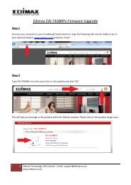
<strong>EW</strong>-<strong>7428HCn</strong><br />
<strong>User</strong> <strong>Manual</strong><br />
08-2012 / v1.0<br />
1
COPYRIGHT<br />
Copyright <strong>Edimax</strong> Technology Co., Ltd. all rights reserved. No part of this publication<br />
may be reproduced, transmitted, transcribed, stored in a retrieval system, or translated<br />
into any language or computer language, in any form or by any means, electronic,<br />
mechanical, magnetic, optical, chemical, manual or otherwise, without the prior written<br />
permission from <strong>Edimax</strong> Technology Co., Ltd.<br />
<strong>Edimax</strong> Technology Co., Ltd. makes no representations or warranties, either expressed or<br />
implied, with respect to the contents hereof and specifically disclaims any warranties,<br />
merchantability, or fitness for any particular purpose. Any software described in this<br />
manual is sold or licensed as is. Should the programs prove defective following their<br />
purchase, the buyer (and not this company, its distributor, or its dealer) assumes the<br />
entire cost of all necessary servicing, repair, and any incidental or consequential damages<br />
resulting from any defect in the software. <strong>Edimax</strong> Technology Co., Ltd. reserves the right<br />
to revise this publication and to make changes from time to time in the contents hereof<br />
without the obligation to notify any person of such revision or changes.<br />
The product you have purchased and the setup screen may appear slightly different from<br />
those shown in this QIG. For more information about this product, please refer to the<br />
user manual on the CD-ROM. The software and specifications are subject to change<br />
without notice. Please visit our website www.edimax.com for updates. All brand and<br />
product names mentioned in this manual are trademarks and/or registered trademarks of<br />
their respective holders.<br />
<strong>Edimax</strong> Technology Co., Ltd.<br />
Add: No. 3, Wu-Chuan 3rd Rd., Wu-Ku Industrial Park, New Taipei City, Taiwan<br />
Tel: +886-2-77396888<br />
Email: sales@edimax.com.tw<br />
Notice According to GNU General Public License Version 2<br />
This product includes software that is subject to the GNU General Public License version<br />
2. The program is free software and distributed without any warranty of the author. We<br />
offer, valid for at least three years, to give you, for a charge no more than the costs of<br />
physically performing source distribution, a complete machine-readable copy of the<br />
corresponding source code.<br />
2
CONTENTS<br />
I. PRODUCT INFORMATION......................................................................................... 5<br />
I-1. Package Contents ............................................................................................ 5<br />
I-2. Physical Description ......................................................................................... 5<br />
I-3. Front Panel ...................................................................................................... 5<br />
I-4. Back Panel ....................................................................................................... 6<br />
I-5. Safety Information ........................................................................................... 7<br />
I-6. System Requirements ...................................................................................... 8<br />
I-7. Hardware Installation ...................................................................................... 8<br />
I-7-I. Connecting the Access Point to a Router or PoE Switch ......................... 8<br />
I-7-2. Fixing the Access Point to a Ceiling ...................................................... 10<br />
II. GETTING STARTED ................................................................................................. 11<br />
II-1. Access Point Mode ........................................................................................... 14<br />
II-2. Universal Wi-Fi Extender Mode ....................................................................... 16<br />
II-3. Wireless Client Mode ...................................................................................... 19<br />
III. BROWSER BASED CONFIGURATION INTERFACE ...................................................... 21<br />
III-1. Home ........................................................................................................... 23<br />
III-2. iQ Setup ....................................................................................................... 25<br />
III-3. Basic Setting ................................................................................................. 26<br />
III-3-1. AP Mode................................................................................................ 28<br />
III-3-2. Station-Infrastructure Mode .................................................................. 33<br />
III-3-3. AP Bridge-Point to Point Mode .............................................................. 35<br />
III-3-4. AP Bridge-Point to Multi-Point Mode .................................................... 36<br />
III-3-5. AP Bridge-WDS ...................................................................................... 38<br />
III-3-6. Universal Repeater Mode ...................................................................... 43<br />
III-4. WPS Setting.................................................................................................. 48<br />
III-5. Wireless Advanced ....................................................................................... 51<br />
III-5-1. Security ................................................................................................. 53<br />
III-5-2. MAC Filtering ........................................................................................ 58<br />
III-6. System Utility ............................................................................................... 60<br />
III-6-1. Administrator ........................................................................................ 61<br />
III-6-2. Time Setting .......................................................................................... 65<br />
III-6-3. Power Saving ......................................................................................... 66<br />
III-6-4. Scheduling setting ................................................................................. 67<br />
III-7. Configuration Tool ........................................................................................ 70<br />
III-7-1. Diagnosis ............................................................................................... 72<br />
III-7-2. Firmware Upgrade ................................................................................. 73<br />
III-7-3. Reboot ................................................................................................... 74<br />
IV. APPENDIX ............................................................................................................ 76<br />
IV-1. Configuring your IP address .......................................................................... 76<br />
IV-1-1. Windows XP .......................................................................................... 76<br />
IV-1-2. Windows Vista ..................................................................................... 77<br />
IV-1-3. Windows 7 ........................................................................................... 79<br />
3
IV-1-4. Mac OS ................................................................................................. 82<br />
IV-2. Troubleshooting ........................................................................................... 86<br />
IV-3. Glossary ........................................................................................................ 88<br />
4
I. PRODUCT INFORMATION<br />
Thank you for purchasing the <strong>Edimax</strong> <strong>EW</strong>-<strong>7428HCn</strong> N300 High Power Ceiling<br />
Mount Wireless PoE Range Extender/Access Point! This device is an ideal<br />
choice for users looking to expand their home or office networking<br />
environment. Its easy installation procedure also allows any computer user to<br />
set up a network environment in a matter of minutes.<br />
I-1.<br />
Package Contents<br />
Before you start using this device, please check if there is anything missing in<br />
the package, and contact your dealer to claim the missing item(s):<br />
• Ceiling mount range extender/access point (1 pcs)<br />
• Quick installation guide (1 pcs)<br />
• CD with multi-language QIG and user manual (1 pcs)<br />
• Power adapter (1 pcs)<br />
• Ethernet cable (1 pcs)<br />
• Mounting kit (1 pcs)<br />
• Access key card (1 pcs)<br />
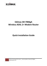
I-2.<br />
Physical Description<br />
3<br />
..<br />
2<br />
1<br />
5 6<br />
4<br />
I-3. Front Panel<br />
LED Light<br />
Status<br />
On<br />
Off<br />
(1)Power<br />
Description<br />
Device correctly powered and initialized.<br />
Device not powered or not correctly powered, or<br />
device not yet initialized.<br />
5
(2)Wi-Fi<br />
(3)LAN<br />
Flashing<br />
On<br />
Flashing<br />
On<br />
Off<br />
Flashing<br />
Device is resetting to factory default settings.<br />
WPS is activated and the device is waiting for a<br />
WPS signal from another device.<br />
Wi-Fi activity (transferring data).<br />
Connected to a local area network.<br />
Not connected to a local area network.<br />
LAN activity (transferring data).<br />
Item Function Description<br />
(4)Reset/<br />
WPS<br />
WPS Press and hold this button for 2 seconds to<br />
activate WPS mode, during which this device will<br />
attempt to automatically connect to a<br />
WPS-enabled client device.<br />
Reset To reset the device to factory default settings,<br />
press and hold the button for 10 seconds, until<br />
the Power LED starts flashing. Release the button<br />
to initiate reset procedures.<br />
Note: Please note that the hardware WPS button<br />
only works when connecting to wireless clients. It<br />
will have no effect when the device itself is in<br />
Wireless Client Mode.<br />
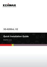
I-4.<br />
Back Panel<br />
Item Name Description<br />
Connects to an Ethernet cable. This device is capable of<br />
Power over Ethernet (PoE), so if the cable is connected<br />
to a PoE switch, then this device will be powered by the<br />
(5) LAN Port Ethernet cable alone.<br />
(6) 5V DC Connects to the power adapter.<br />
Note: Please do not connect the power adapter if<br />
the device is already connected to a PoE switch via<br />
the LAN port.<br />
6
I-5.<br />
Safety Information<br />
In order to ensure the safe operation of the device and its users, please read<br />
and act in accordance with the following safety instructions.<br />
1. The access point is designed for indoor use only; do not place the access<br />
point outdoors.<br />
2. Do not place the access point in or near hot/humid places, such as a kitchen<br />
or bathroom.<br />
3. Do not pull any connected cable with force; carefully disconnect it from the<br />
access point.<br />
4. Ensure that the access point is firmly secured to a wall or ceiling. In the<br />
event of damage due to the access point falling from its location, the<br />
warranty of the access point is void.<br />
5. The device contains small parts which are a danger to small children under<br />
3 years old. Please keep the access point out of reach of children.<br />
6. Do not place the access point on paper, cloth, or other flammable materials.<br />
The access point will become hot during use.<br />
7. There are no user-serviceable parts inside the access point. If you<br />
experience problems with the access point, please contact your dealer of<br />
purchase and ask for help.<br />
8. The access point is an electrical device and as such, if it becomes wet for<br />
any reason, do not attempt to touch it without switching the power supply<br />
off. Contact an experienced electrical technician for further help.<br />
9. If you smell burning or see smoke coming from access point or A/C power<br />
adapter, then disconnect the access point and A/C power adapter<br />
immediately, as far as it is safely possible to do so. Call your dealer of<br />
purchase for help.<br />
7
I-6.<br />
System Requirements<br />
- Computer or network device with wired or wireless network interface<br />
card.<br />
- Web browser (Microsoft Internet Explorer 7.0 or above, Opera web<br />
browser, or Safari web browser).<br />
- Available AC power socket (100 – 240 V, 50/60Hz) or 802.3af Power<br />
Over Ethernet (PoE) Switch.<br />
I-7.<br />
Hardware Installation<br />
The access point can be attached to a ceiling, or connected to a router or PoE<br />
switch.<br />
Note: You must first configure your access point<br />
using iQ Setup before proceeding with hardware<br />
installation. The following is for reference after you<br />
have chosen which mode to operate your access<br />
point. Please refer to II. Getting Started and follow<br />
the instructions to configure your access point.<br />
I-7-I.<br />
Connecting the Access Point to a Router or PoE Switch<br />
1. To connect the access point to a router or Power over Ethernet (PoE) switch,<br />
first carefully remove the back panel cover by twisting it counter-clockwise.<br />
This enables easier access to the LAN port and the power adapter.<br />
2. Plug one end of an Ethernet cable into the Ethernet port on the access<br />
point. Plug the other end of the cable into a LAN port on a router or PoE<br />
switch, as shown in the following diagram:<br />
8
3. If you are using a router then plug the power adapter into a wall socket,<br />
and connect it to the 5V DC power port on the access point. Reattach the<br />
back panel cover, twisting it clockwise to secure it into place.<br />
4. If you are using a PoE switch then it is not necessary to connect the access<br />
point to a power source via the 5V DC power adapter. The device will be<br />
powered by the PoE switch. Reattach the back panel cover, twisting it<br />
clockwise to secure it into place.<br />
Note: If you are using a Power over Ethernet (PoE)<br />
switch, do not use the power adapter included in<br />
the package contents.<br />
9
I-7-2.<br />
Fixing the Access Point to a Ceiling<br />
1. To attach the device to the ceiling in its final location, attach the device’s<br />
back panel to the ceiling with the included screws (mounting kit). Then,<br />
attach the rest of the device to the back panel, twisting it clockwise to lock<br />
it into place.<br />
10
II. GETTING STARTED<br />
1. Carefully remove the back panel cover by twisting it counter-clockwise. This<br />
enables easier access to the LAN port and the power adapter.<br />
2. Plug one end of an Ethernet cable into the device’s Ethernet port, plug the<br />
other end into your computer’s Ethernet port.<br />
3. Plug the power adapter into a wall socket, then connect it to the 5V DC<br />
power port. Reattach the back panel cover, twisting it clockwise to secure it<br />
into place.<br />
4. The device will begin to initialize. After 30 seconds, the power LED will turn<br />
on, which indicates the device has completed its initialization.<br />
Note: Make sure that your computer is set as a<br />
DHCP client. If you are unsure, please see APPENDIX<br />
IV-1. Configuring your IP address to set your PC IP<br />
to “Obtain an IP address automatically”.<br />
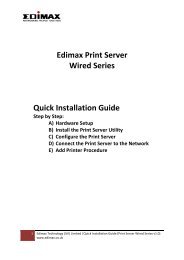
5. Enclosed in the product box is an Access Key card to indicate device factory<br />
default information, containing a URL to access the device’s browser-based<br />
configuration interface, similar to the example below.<br />
“Web browser access” is necessary information for you to login web-based<br />
firmware.<br />
“Wi-Fi Client access” is necessary information for your wireless client<br />
device(for example your computer, tablet, smart phone) to connect to this<br />
device.<br />
11
Note: The URL on your card will likely differ from<br />
the example shown in this guide. Please enter the<br />
URL you see on your card, and not the URL used in<br />
the examples here.<br />
6. Open a web browser, such as Internet Explorer. Enter the access key into<br />
the browser URL bar. (Windows PCs only)<br />
Or enter the default IP address (http://192.168.2.2) into your browser’s<br />
address bar. (MacOS and Linux)<br />
7. You will be prompted to enter a username and password. The default<br />
username is admin, and the default password is 1234.<br />
12
<br />
8. You will then enter the iQ Setup screen, where you can choose which mode<br />
to activate.<br />
The default mode for the device is Access Point Mode.<br />
1. For Access Point Mode, please see section II-1. Access Point Mode<br />
2. For Universal Wi-Fi Extender Mode, please see section II-2. Universal Wi-Fi Extender Mode<br />
3. For Wireless Client Mode, please see section II-3. Wireless Client Mode<br />
13
II-1.<br />
Access Point Mode<br />
Access Point Mode allows the device to broadcast a wireless Internet signal,<br />
which your wireless devices – such as a notebook computer, a smartphone, or<br />
a tablet computer – can connect to.<br />
1. Select Access Point Mode from the iQ Setup list.<br />
2. You will be asked if you want to change the login information for this device.<br />
For now, simply click ‘NEXT’ without changing anything. You will later have<br />
an opportunity to change this in the browser-based setup, should you wish.<br />
Note: If you changed the username and password in<br />
this step, you will be prompted to relogin. Enter the<br />
new information into the login prompt.<br />
3. You will be prompted to set the device’s access point settings. If you want<br />
to, you can give the device an ID in the ‘Device Name’ field, and if you want<br />
to set a Wi-Fi password, select ‘Enabled’ from the drop-down menu and<br />
enter your desired password in the ‘Wi-Fi Network Password field’.<br />
Otherwise, if you keep the default settings, the device’s wireless network<br />
will have the default ID of ‘<strong>Edimax</strong>’ and will use no password.<br />
14
Note: If the device is not set to “Obtain an IP<br />
address automatically”, then please select that<br />
option by clicking on the radio button circled in the<br />
above image.<br />
4. Click ‘APPLY’ when you are done. You will see a confirmation screen, with<br />
your Wi-Fi settings.<br />
5. Click ‘APPLY’ and the device will save settings and restart. When it has<br />
finished, you will see a final congratulations screen.<br />
6. Disconnect the access point from your computer via Ethernet cable and<br />
connect the access point to a router or PoE switch. See I-7-I. Connecting<br />
the Access Point to a Router or Power over Ethernet (PoE) Switch.<br />
In the diagram below, the access point is connected to a PoE switch:<br />
15
7. You may now connect to the device wirelessly by selecting its ID from your<br />
list of Wi-Fi networks, and entering the password you set (if you set one).<br />
II-2.<br />
Universal Wi-Fi Extender Mode<br />
Universal Wi-Fi Extender Mode allows you to extend the range of an existing<br />
Wi-Fi network; expanding wireless coverage and eliminating dead spots.<br />
1. Select Universal Wi-Fi Extender Mode from the list. iQ Setup will start<br />
detecting available Wi-Fi networks automatically. All detected Wi-Fi<br />
networks will be displayed in the list. Select the one you wish to connect to.<br />
Note: If the Wi-Fi network you wish to connect to<br />
does not appear, click “Refresh” to detect again or<br />
try to move the device closer to the root wireless<br />
access point.<br />
2. Input the password of the existing Wi-Fi network in the “Key” field and click<br />
“Next” to continue. The device must have the same Wi-Fi password as the<br />
root wireless access point.<br />
Note: The device will be unable to connect to the<br />
Wi-Fi network if you enter the wrong password. If<br />
you do not know your Wi-Fi password, you may find<br />
it via your Wi-Fi router’s configuration, or consult<br />
the network administrator who set up the Wi-Fi<br />
16
network.<br />
3. By default, the device’s SSID is the root access point’s SSID plus the last six<br />
characters of the device’s access key. You can change the device’s SSID if<br />
you want. Click “Next” to complete the setup.<br />
4. The device will test the connection between itself and the root wireless<br />
access point.<br />
If the connection is successful, the message “Connection Test Successfully”<br />
will appear on-screen. Click “Next” to save settings.<br />
If the connection failed, the message “Connection Test Failed” will appear<br />
on-screen. Click “Back” to restart the setup process.<br />
5. The device will show a brief summary of the name of the root wireless<br />
access point, the name of the device, and the security type used. Click<br />
“APPLY” to continue, or click “Back” to restart the setup process.<br />
6. After you click “APPLY” the device will restart and save its settings. You will<br />
see a final congratulations page. Your computer will be disconnected from<br />
the extender at this time. To reconnect to the extender, select its SSID from<br />
your list of Wi-Fi networks.<br />
17
7. You may test the connectivity of the device by disconnecting the Ethernet<br />
cable from your computer’s Ethernet port, and then attempting to connect<br />
to the device wirelessly (select its SSID from your list of wireless networks,<br />
not the SSID of your root Wi-Fi access point). Then, attempt to open a web<br />
page with your web browser.<br />
8. After you have connected the device to the existing Wi-Fi network and<br />
confirmed it works, you can move this device to another location for<br />
optimal Wi-Fi extension. To move the device, turn it off and unplug it from<br />
its socket. The device will remember the Wi-Fi network it is assigned to.<br />
Move the device to its new location and plug it in, then turn the device on<br />
again. It will go through its initialization process after being turned on. You<br />
will be unable to connect to the device while it is initializing.<br />
18
II-3. Wireless Client Mode<br />
Wireless Client Mode allows Ethernet devices such as smart televisions and<br />
video game consoles to connect to a wireless access point.<br />
1. Select Wireless Client Mode from the list. iQ Setup will start detecting<br />
available Wi-Fi networks automatically. All detected Wi-Fi networks will be<br />
displayed in the list. Select the one you wish to connect to.<br />
Note: If the Wi-Fi network you wish to connect to<br />
does not appear, click “Refresh” to detect again or<br />
try to move the device closer to the root wireless<br />
access point.<br />
2. Input the password of the existing Wi-Fi network in the “Key” field and click<br />
“Next” to continue. The device must have the same Wi-Fi password as the<br />
root wireless access point.<br />
Note: The device will be unable to connect to the<br />
Wi-Fi network if you enter the wrong password. If<br />
you do not know your Wi-Fi password, you may find<br />
it via your Wi-Fi router’s configuration, or consult<br />
the network administrator who set up the Wi-Fi<br />
network.<br />
3. The device will test the connection between itself and the root wireless<br />
access point.<br />
19
If the connection is successful, the message “Connection Successfully” will<br />
appear on-screen. Click “Next” to save settings.<br />
If the connection failed, the message “Connection Test Failed” will appear<br />
on-screen. Click “Back” to restart the setup process.<br />
4. The device will show a brief summary of the name of the root wireless<br />
access point, the name of the device, and the security type used. Click<br />
“APPLY” to continue, or click “Back” to restart the setup process.<br />
5. After you click “APPLY” the device will restart and save its settings. You will<br />
see a final congratulations page.<br />
6. You may now transfer this device to another Ethernet appliance, such as a<br />
computer, a smart TV or a game console, by disconnecting the Ethernet<br />
cable from your computer’s Ethernet port, and then connecting it to the<br />
appliance’s Ethernet port. The device will remember the wireless network it<br />
is assigned to.<br />
20
III. BROWSER BASED CONFIGURATION INTERFACE<br />
9. The configurations and settings of this device may be accessed through the<br />
browser-based configuration interface. Enclosed in the product box is an<br />
Access Key card to indicate device factory default information, containing a<br />
URL to access the device’s browser-based configuration interface, similar to<br />
the example below.<br />
“Web browser access” is necessary information for you to login web-based<br />
firmware.<br />
“Wi-Fi Client access” is necessary information for your wireless client<br />
device(for example your computer, tablet, smart phone) to connect to this<br />
device.<br />
.<br />
Note: The URL on your card will likely differ from<br />
the example shown in this guide. Please enter the<br />
URL you see on your card, and not the URL used in<br />
the examples here.<br />
Open a web browser, such as Internet Explorer. Enter the access key<br />
(http://edimax******) or default IP address into the browser URL bar.<br />
(Windows PCs only)<br />
21
For Mac users, enter the default IP address (http://192.168.2.2) into your<br />
browser’s address bar. (MacOS and Linux)<br />
Note: The access point uses the default IP address<br />
192.168.2.2, which may not be in the same IP address<br />
subnet of your network. Accordingly, you may need to<br />
modify the IP address of your PC or Macintosh to<br />
192.168.2.10, before you can access the browser-based<br />
configuration interface.<br />
In the event that you cannot access the browser-based<br />
configuration interface using either the access key or<br />
the default IP address, please refer to IV-1. Configuring<br />
your IP Address for guidance on how to modify your IP<br />
address.<br />
Note: For guidance on how to assign a new IP address<br />
to the access point, so that it is within the same IP<br />
address subnet of your network, please refer to III-6-1.<br />
Administrator. If the default IP of the access point<br />
remains unchanged, you may need to repeat this<br />
process and modify the IP of your PC or Macintosh<br />
every time you wish to configure the access point.<br />
You will be prompted to enter the device’s username and password. The<br />
default username is admin and the default password is 1234.<br />
22
<br />
Options are listed in the sidebar on the left side of the interface.<br />
.<br />
III-1.<br />
Home<br />
The Home page shows the basic status and information of the device.<br />
23
Note: This screenshot is an example. The<br />
information you see on your screen will likely differ<br />
from this screenshot.<br />
Uptime<br />
Hardware<br />
Version<br />
Runtime Code<br />
Version<br />
Mode<br />
ESSID<br />
Channel<br />
Displays the total passed time since the<br />
device was turned on<br />
Displays the hardware version. This<br />
information is helpful when you need online<br />
help from the dealer of purchase.<br />
Displays the current firmware version. If you<br />
want to perform a firmware upgrade, this<br />
number will help you to determine if you<br />
have the latest version of the firmware.<br />
Displays the current wireless operating<br />
mode (see next section)<br />
Displays the current ESSID (the name used<br />
to identify this wireless access point)<br />
Displays the current wireless channel<br />
24
Number<br />
Security<br />
BSSID (MAC)<br />
Associated<br />
Clients<br />
Show Active<br />
Clients<br />
IP Address<br />
Subnet Mask<br />
Default<br />
Gateway<br />
MAC address<br />
number<br />
Displays the current wireless security setting<br />
Displays the device’s MAC address. A MAC<br />
address is a unique identifier for this device,<br />
it cannot be modified by users)<br />
Displays the number of connected wireless<br />
client<br />
Displays a list of connected devices, along<br />
with relevant information on each one<br />
Displays the IP address of this device<br />
Displays the subnet mask of the IP address<br />
Displays the IP address of the default<br />
gateway<br />
Displays the MAC address of the LAN<br />
interface<br />
III-2.<br />
iQ Setup<br />
If you wish to perform the initial setup process again, for example to change<br />
the operation mode of the device, select iQ Setup to restart the setup process.<br />
This will bring you back to the initial setup screen.<br />
25
III-3.<br />
Basic Setting<br />
This device can be set to operate in different modes. You can select the mode<br />
you want by selecting Basic Setting from the sidebar.<br />
26
You can select a mode of operation from the drop-down menu.<br />
There are six modes available:<br />
AP<br />
Access point mode, allows wireless clients<br />
to connect to this device and exchange data<br />
with the devices connected to the wired<br />
network.<br />
Station-Infrastructure Also known as wireless client mode. Enables<br />
Ethernet-only devices such as smart TVs and<br />
game consoles to connect to a wireless<br />
AP Bridge-Point to<br />
Point<br />
network<br />
Establishes a wireless connection with<br />
another wireless access point using the<br />
27
III-3-1.<br />
AP Bridge-Point to<br />
Multi-Point<br />
AP Bridge-WDS<br />
Universal Repeater<br />
AP Mode<br />
same mode, and links any wired networks<br />
connected to these two wireless access<br />
points together. Only one access point can<br />
be connected in this mode.<br />
Establishes a wireless connection with other<br />
wireless access points using the same mode,<br />
and links any wired networks connected to<br />
these wireless access points together. Up to<br />
4 access points can be connected in this<br />
mode.<br />
This mode is similar to “AP Bridge to<br />
Multi-Point”, but the device is not in<br />
bridge-dedicated mode, and will be able to<br />
accept wireless clients while the device is<br />
working as a wireless bridge.<br />
The device will act as a wireless range<br />
extender that will help you to extend your<br />
Wi-Fi network. The device acts as a client<br />
and AP at the same time. It its client<br />
function to connect to a root AP, and uses<br />
its AP function to service wireless clients<br />
within its coverage.<br />
When in AP mode, this device acts as a bridge between IEEE 802.11b/g/n<br />
wireless devices and a wired Ethernet network, and exchanges data between<br />
them.<br />
When you select AP Mode, the following appears:<br />
28
Band<br />
Please select the wireless band you wish to<br />
use. By selecting different band settings,<br />
you’ll be able to allow or deny wireless<br />
clients using certain bands.<br />
If you select 2.4GHz (B), 2.4GHz (N), or<br />
2.4GHz (G), only wireless clients using the<br />
wireless band you select (802.11b, 802.11n,<br />
or 802.11g) will be able to connect to this<br />
access point.<br />
If you select 2.4GHz (B+G), then only<br />
wireless clients using the 802.11b and<br />
802.11g bands will be able to connect to<br />
this access point.<br />
MAIN ESSID<br />
Multiple ESSID<br />
AP Isolation<br />
SSID Isolation<br />
If you want to allow 802.11b, 802.11g, and<br />
802.11n clients to connect to this access<br />
point, select 2.4GHz (B+G+N).<br />
Please input the ESSID (the name used to<br />
identify this wireless access point) here. You<br />
can input up to 32 alphanumerical<br />
characters. Please note that the ESSID is<br />
case sensitive.<br />
When you press this button, a new window<br />
will appear, allowing you to assign up to<br />
four ESSIDs to this access point. Please see<br />
the following page for more details.<br />
When this is set to “Enabled”, wireless<br />
clients connected to this device will be able<br />
to access the Internet, but will not be able<br />
to communicate with each other. This<br />
applies to clients connected to the MAIN<br />
ESSID only.<br />
When the access point uses multiple SSIDs<br />
and this is set to “Enabled”, then wireless<br />
clients connected to the same SSID will be<br />
able to communicate with each other, but<br />
will not be able to communicate with other<br />
wireless clients connected to another of this<br />
29
Channel<br />
Number<br />
Associated<br />
Clients<br />
access point’s SSIDs. You can input a<br />
numeric VLAD ID value between 1 – 4094<br />
for the MAIN ESSID.<br />
Please select a channel number you wish to<br />
use. If you know a certain channel number<br />
is being used by other wireless access points<br />
nearby, please refrain from using the same<br />
channel number<br />
Click the “Show Active Clients” button and a<br />
new window will appear, which contains<br />
information about all wireless clients<br />
connected to this access point. You can click<br />
the “Refresh” button in the popup window<br />
to keep the information up-to-date.<br />
Click “APPLY” to make changes take effect. The following message will appear:<br />
Click “CONTINUE” to save the changes but not apply them yet. This allows you<br />
to make further changes in the browser-based management interface, before<br />
applying them all at once.<br />
Click “APPLY” to restart the device and implement any changes. The device will<br />
restart itself.<br />
Multiple ESSID<br />
When you click the “Multiple ESSID” button, a new window will open, as<br />
shown below. This page allows you to configure the wireless settings for<br />
multiple ESSID’s.<br />
Note: The security settings for multiple ESSID’s can<br />
be configured from the Security screen. Please see<br />
III-5-1. Security for more information.<br />
30
No.<br />
Enable<br />
SSID<br />
Broadcast SSID<br />
WMM<br />
Band<br />
Displayed here is the number of each<br />
additional ESSID.<br />
Check the box to enable or disable a specific<br />
ESSID accordingly.<br />
Please input the ESSID (the name used to<br />
identify this wireless access point) here. You<br />
can input up to 32 alphanumerical<br />
characters. Please note that the ESSID is<br />
case sensitive.<br />
Decide if the device will broadcast its own<br />
ESSID. You can hide the ESSID of your<br />
wireless access point (set the option to<br />
“Disable”), so only people who know the<br />
ESSID of your wireless access point can<br />
connect to it.<br />
WMM (Wi-Fi Multimedia) technology can<br />
improve the performance of certain<br />
network applications, such as audio/video<br />
streaming, network telephony (VoIP), and<br />
others. When you enable WMM, the access<br />
point will define the priority of different<br />
kinds of data, to give higher priority to<br />
applications which require instant<br />
responses. This improves the performance<br />
of such network applications.<br />
Please select the wireless band you wish to<br />
use. By selecting different band settings,<br />
31
you’ll be able to allow or deny wireless<br />
clients using certain bands.<br />
If you select 2.4GHz (B), 2.4GHz (N), or<br />
2.4GHz (G), only wireless clients using the<br />
wireless band you select (802.11b, 802.11n,<br />
or 802.11g) will be able to connect to this<br />
access point.<br />
If you select 2.4GHz (B+G), then only<br />
wireless clients using the 802.11b and<br />
802.11g bands will be able to connect to<br />
this access point.<br />
AP Isolation<br />
SSID Isolation<br />
If you want to allow 802.11b, 802.11g, and<br />
802.11n clients to connect to this access<br />
point, select 2.4GHz (B+G+N).<br />
When this is set to “Enabled”, wireless<br />
clients connected to this device will be able<br />
to access the Internet, but will not be able<br />
to communicate with each other. This<br />
applies to clients connected to the specified<br />
ESSID only.<br />
When the access point uses multiple SSIDs<br />
and this is set to “Enabled”, then wireless<br />
clients connected to the same SSID will be<br />
able to communicate with each other, but<br />
will not be able to communicate with other<br />
wireless clients connected to another of this<br />
access point’s SSIDs. You can input a<br />
numeric VLAD ID value between 1 – 4094<br />
for each specific ESSID.<br />
Click “APPLY” to make changes take effect. The following message will appear:<br />
Click “OK” to return to the “Basic Setting” screen.<br />
32
III-3-2.<br />
Station-Infrastructure Mode<br />
When in Station-Infrastructure mode, the device acts as a wireless client, and<br />
can be connected to Ethernet-only Internet devices, such as smart televisions<br />
or video game consoles. This gives these devices the capability to connect to<br />
the Internet wirelessly.<br />
Band<br />
Please select the wireless band you wish to<br />
use. By selecting different band settings,<br />
you’ll be able to allow or deny access points<br />
using certain bands.<br />
If you select 2.4GHz (B), 2.4GHz (N), or<br />
2.4GHz (G), only access points using the<br />
wireless band you select (802.11b, 802.11n,<br />
or 802.11g) will be able to connect to this<br />
device.<br />
If you select 2.4GHz (B+G), then only access<br />
points using the 802.11b and 802.11g bands<br />
will be able to connect to this device.<br />
MAIN ESSID<br />
If you want to allow 802.11b, 802.11g, and<br />
802.11n access points to connect to this<br />
device, select 2.4GHz (B+G+N).<br />
Please input the ESSID (the name used to<br />
identify the wireless device) of the access<br />
point you want to connect to here. You can<br />
input up to 32 alphanumerical characters.<br />
Please note that the ESSID is case sensitive.<br />
33
Site Survey<br />
When you use this device to give an<br />
Ethernet network device wireless capability,<br />
you have to associate it with a working<br />
access point. Click the “Select Site Survey”<br />
button, and a “Wireless Site Survey Table”<br />
will pop up. It will list all available access<br />
points nearby. Select one access point in the<br />
table for this device to connect to. (Please<br />
see below)<br />
Click “APPLY” to make changes take effect. The following message will appear:<br />
Click “CONTINUE” to save the changes but not apply them yet. This allows you<br />
to make further changes in the browser-based management interface, before<br />
applying them all at once.<br />
Click “APPLY” to restart the device and implement any changes. The device will<br />
restart itself.<br />
Wireless Site Survey<br />
When you click the “Select Site Survey” button, a “Wireless Site Survey Table”<br />
will pop up. It will list all available access points nearby.<br />
If you don’t see the SSID of the access point you wish to connect to, you may<br />
try clicking the “Refresh” button. It is also possible the access point has hidden<br />
34
its SSID, in which case you will need to manually enter the SSID in the “MAIN<br />
SSID” field on the previous page.<br />
III-3-3.<br />
AP Bridge-Point to Point Mode<br />
In this mode, the access point connects to another wireless access point in the<br />
same mode, and all connected Ethernet clients of both devices will be<br />
connected together. This allows two physically isolated networks to<br />
communicate with each other.<br />
Note: When you set the device to this mode, it will<br />
not accept regular wireless clients any more.<br />
Band<br />
Please select the wireless band you wish to<br />
use. By selecting different band settings,<br />
you’ll be able to allow or deny access points<br />
using certain bands.<br />
If you select 2.4GHz (B), 2.4GHz (N), or<br />
2.4GHz (G), only access points using the<br />
wireless band you select (802.11b, 802.11n,<br />
or 802.11g) will be able to connect to this<br />
device.<br />
If you select 2.4GHz (B+G), then only access<br />
points using the 802.11b and 802.11g bands<br />
will be able to connect to this device.<br />
Channel<br />
If you want to allow 802.11b, 802.11g, and<br />
802.11n access points to connect to this<br />
device, select 2.4GHz (B+G+N).<br />
Please select the channel number you wish<br />
35
Number<br />
MAC address 1<br />
Set Security<br />
to use. The channel number must be same<br />
as the other wireless access point you wish<br />
to connect to.<br />
Please input the MAC address of the<br />
wireless access point you wish to connect<br />
to.<br />
Click this button to select an encryption<br />
mode for this wireless link. A popup window<br />
with security options will appear.<br />
Click “APPLY” to make changes take effect. The following message will appear:<br />
Click “CONTINUE” to save the changes but not apply them yet. This allows you<br />
to make further changes in the browser-based management interface, before<br />
applying them all at once.<br />
Click “APPLY” to restart the device and implement any changes. The device will<br />
restart itself.<br />
III-3-4.<br />
AP Bridge-Point to Multi-Point Mode<br />
In this mode, this access point will connect to up to four other wireless access<br />
points also using the same mode, and all connected Ethernet clients of all<br />
access points will be connected together. This allows several physically isolated<br />
networks to communicate with each other.<br />
Note: When you set the device to this mode, it will<br />
not accept regular wireless clients any more.<br />
36
Band<br />
Please select the wireless band you wish to<br />
use. By selecting different band settings,<br />
you’ll be able to allow or deny access points<br />
using certain bands.<br />
If you select 2.4GHz (B), 2.4GHz (N), or<br />
2.4GHz (G), only access points using the<br />
wireless band you select (802.11b, 802.11n,<br />
or 802.11g) will be able to connect to this<br />
device.<br />
If you select 2.4GHz (B+G), then only access<br />
points using the 802.11b and 802.11g bands<br />
will be able to connect to this device.<br />
Channel<br />
Number<br />
MAC address<br />
1-4<br />
Set Security<br />
If you want to allow 802.11b, 802.11g, and<br />
802.11n access points to connect to this<br />
device, select 2.4GHz (B+G+N).<br />
Please select a channel number you wish to<br />
use. The channel number must be same as<br />
the other wireless access points you wish to<br />
connect to.<br />
Please input the MAC addresses of the<br />
wireless access points you wish to connect<br />
to.<br />
Click this button to select an encryption<br />
mode for this wireless link. A popup window<br />
37
with security options will appear.<br />
Click “APPLY” to make changes take effect. The following message will appear:<br />
Click “CONTINUE” to save the changes but not apply them yet. This allows you<br />
to make further changes in the browser-based management interface, before<br />
applying them all at once.<br />
Click “APPLY” to restart the device and implement any changes. The device will<br />
restart itself.<br />
III-3-5.<br />
AP Bridge-WDS<br />
In this mode, this access point will connect to up to four other wireless access<br />
points also using the same mode, and all connected Ethernet clients of all<br />
access points will be connected together. This allows several physically isolated<br />
networks to communicate with each other.<br />
Note: When you set the device to this mode, it will<br />
still be able to accept regular wireless clients.<br />
38
Band<br />
Please select the wireless band you wish to<br />
use. By selecting different band settings,<br />
you’ll be able to allow or deny devices using<br />
certain bands.<br />
If you select 2.4GHz (B), 2.4GHz (N), or<br />
2.4GHz (G), only devices using the wireless<br />
band you select (802.11b, 802.11n, or<br />
802.11g) will be able to connect to this<br />
device.<br />
If you select 2.4GHz (B+G), then only<br />
devices using the 802.11b and 802.11g<br />
bands will be able to connect to this device.<br />
MAIN ESSID<br />
Multiple ESSID<br />
AP Isolation<br />
SSID Isolation<br />
If you want to allow 802.11b, 802.11g, and<br />
802.11n devices to connect to this device,<br />
select 2.4GHz (B+G+N).<br />
Please input the ESSID (the name used to<br />
identify this wireless access point) here. You<br />
can input up to 32 alphanumerical<br />
characters. Please note that the ESSID is<br />
case sensitive.<br />
When you press this button, a new window<br />
will appear, allowing you to assign up to<br />
four ESSIDs to this access point. Please see<br />
the following page for more details.<br />
When this is set to “Enabled”, wireless<br />
clients connected to this device will be able<br />
to access the Internet, but will not be able<br />
to communicate with each other. This<br />
applies to clients connected to the MAIN<br />
ESSID only.<br />
When the access point uses multiple SSIDs<br />
and this is set to “Enabled”, then wireless<br />
clients connected to the same SSID will be<br />
able to communicate with each other, but<br />
will not be able to communicate with other<br />
wireless clients connected to another of this<br />
39
Channel<br />
Number<br />
Associated<br />
Clients<br />
MAC address<br />
1-4<br />
Set Security<br />
access point’s SSIDs. You can input a<br />
numeric VLAD ID value between 1 – 4094<br />
for the MAIN ESSID.<br />
Please select a channel number you wish to<br />
use. The channel number must be same as<br />
the other wireless access points you wish to<br />
connect to.<br />
Click the “Show Active Clients” button and a<br />
new window will appear, which contains<br />
information about all wireless clients<br />
connected to this access point. You can click<br />
the “Refresh” button in the popup window<br />
to keep the information up-to-date.<br />
Please input the MAC addresses of the<br />
wireless access point you wish to connect<br />
to.<br />
Click this button to select an encryption<br />
mode for this wireless link. A popup window<br />
with security options will appear.<br />
Click “APPLY” to make changes take effect. The following message will appear:<br />
Click “CONTINUE” to save the changes but not apply them yet. This allows you<br />
to make further changes in the browser-based management interface, before<br />
applying them all at once.<br />
Click “APPLY” to restart the device and implement any changes. The device will<br />
restart itself.<br />
Multiple ESSID<br />
When you click the “Multiple ESSID” button, a new window will open, as<br />
shown below. This page allows you to configure the wireless settings for<br />
40
multiple ESSID’s.<br />
Note: The security settings for multiple ESSID’s can<br />
be configured from the Security screen. Please see<br />
III-5-1. Security for more information.<br />
No.<br />
Enable<br />
SSID<br />
Broadcast SSID<br />
WMM<br />
Displayed here is the number of each<br />
additional ESSID.<br />
Check the box to enable or disable a specific<br />
ESSID accordingly.<br />
Please input the ESSID (the name used to<br />
identify this wireless access point) here. You<br />
can input up to 32 alphanumerical<br />
characters. Please note that the ESSID is<br />
case sensitive.<br />
Decide if the device will broadcast its own<br />
ESSID. You can hide the ESSID of your<br />
wireless access point (set the option to<br />
“Disable”), so only people who know the<br />
ESSID of your wireless access point can<br />
connect to it.<br />
WMM (Wi-Fi Multimedia) technology can<br />
improve the performance of certain<br />
network applications, such as audio/video<br />
streaming, network telephony (VoIP), and<br />
others. When you enable WMM, the access<br />
point will define the priority of different<br />
41
Band<br />
kinds of data, to give higher priority to<br />
applications which require instant<br />
responses. This improves the performance<br />
of such network applications.<br />
Please select the wireless band you wish to<br />
use. By selecting different band settings,<br />
you’ll be able to allow or deny wireless<br />
clients using certain bands.<br />
If you select 2.4GHz (B), 2.4GHz (N), or<br />
2.4GHz (G), only wireless clients using the<br />
wireless band you select (802.11b, 802.11n,<br />
or 802.11g) will be able to connect to this<br />
access point.<br />
If you select 2.4GHz (B+G), then only<br />
wireless clients using the 802.11b and<br />
802.11g bands will be able to connect to<br />
this access point.<br />
AP Isolation<br />
SSID Isolation<br />
If you want to allow 802.11b, 802.11g, and<br />
802.11n clients to connect to this access<br />
point, select 2.4GHz (B+G+N).<br />
When this is set to “Enabled”, wireless<br />
clients connected to this device will be able<br />
to access the Internet, but will not be able<br />
to communicate with each other. This<br />
applies to clients connected to the specified<br />
ESSID only.<br />
When the access point uses multiple SSIDs<br />
and this is set to “Enabled”, then wireless<br />
clients connected to the same SSID will be<br />
able to communicate with each other, but<br />
will not be able to communicate with other<br />
wireless clients connected to another of this<br />
access point’s SSIDs. You can input a<br />
numeric VLAD ID value between 1 – 4094<br />
for each specific ESSID.<br />
Click “APPLY” to make changes take effect. The following message will appear:<br />
42
Click “OK” to return to the “Basic Setting” screen.<br />
III-3-6.<br />
Universal Repeater Mode<br />
In this mode, this device acts as a wireless extender, simultaneously<br />
performing the functions of a client and an access point. It can extend the<br />
wireless signal of an access point, thus expanding Wi-Fi coverage and<br />
eliminating dead spots.<br />
Note: In repeater mode, this device will demodulate<br />
the received signal, check the noise level, then<br />
modulate and amplify the signal again. The output<br />
power of this mode is the same as that of WDS and<br />
normal AP mode.<br />
Band<br />
Please select the wireless band you wish to<br />
use. By selecting different band settings,<br />
you’ll be able to allow or deny devices using<br />
certain bands.<br />
If you select 2.4GHz (B), 2.4GHz (N), or<br />
2.4GHz (G), only devices using the wireless<br />
band you select (802.11b, 802.11n, or<br />
802.11g) will be able to connect to this<br />
device.<br />
43
If you select 2.4GHz (B+G), then only<br />
devices using the 802.11b and 802.11g<br />
bands will be able to connect to this device.<br />
MAIN SSID<br />
Multiple ESSID<br />
AP Isolation<br />
SSID Isolation<br />
Channel<br />
Number<br />
Associated<br />
Clients<br />
Root AP SSID<br />
If you want to allow 802.11b, 802.11g, and<br />
802.11n devices to connect to this device,<br />
select 2.4GHz (B+G+N).<br />
Please input the ESSID (the name used to<br />
identify this wireless access point) here. You<br />
can input up to 32 alphanumerical<br />
characters. Please note that the ESSID is<br />
case sensitive.<br />
When you press this button, a new window<br />
will appear, allowing you to assign up to<br />
four ESSIDs to this access point. Please see<br />
the following page for more details.<br />
When this is set to “Enabled”, wireless<br />
clients connected to this device will be able<br />
to access the Internet, but will not be able<br />
to communicate with each other. This<br />
applies to clients connected to the MAIN<br />
ESSID only.<br />
When the access point uses multiple SSIDs<br />
and this is set to “Enabled”, then wireless<br />
clients connected to the same SSID will be<br />
able to communicate with each other, but<br />
will not be able to communicate with other<br />
wireless clients connected to another of this<br />
access point’s SSIDs. You can input a<br />
numeric VLAN ID value between 1 – 4094<br />
for the MAIN ESSID.<br />
Please select a channel number you wish to<br />
use. The channel number must be same as<br />
the other wireless access points you wish to<br />
connect to.<br />
Click the “Show Active Clients” button and a<br />
new window will appear, which contains<br />
information about all wireless clients<br />
connected to this access point. You can click<br />
the “Refresh” button in the popup window<br />
to keep the information up-to-date.<br />
In Universal Repeater mode, this device will<br />
44
Select Site<br />
Survey<br />
act as a station and connect to a root AP.<br />
Enter the SSID of the root AP here, or click<br />
the “Select Site Survey” button to choose a<br />
root AP.<br />
Click the “Select Site Survey” button, and a<br />
“Wireless Site Survey Table” will pop up. It<br />
will list all available access points nearby.<br />
Select one access point in the table for this<br />
device to connect to. (Please see below)<br />
Click “APPLY” to make changes take effect. The following message will appear:<br />
Click “CONTINUE” to save the changes but not apply them yet. This allows you<br />
to make further changes in the browser-based management interface, before<br />
applying them all at once.<br />
Click “APPLY” to restart the device and implement any changes. The device will<br />
restart itself.<br />
Wireless Site Survey<br />
When you click the “Select Site Survey” button, a “Wireless Site Survey Table”<br />
will pop up. It will list all available access points nearby.<br />
If you don’t see the SSID of the access point you wish to connect to, you may<br />
try clicking the “Refresh” button. It is also possible the access point has hidden<br />
its SSID, in which case you will need to manually enter the SSID in the “MAIN<br />
45
SSID” field on the previous page.<br />
Multiple ESSID<br />
When you click the “Multiple ESSID” button, a new window will open, as<br />
shown below. This page allows you to configure the wireless settings for<br />
multiple ESSID’s.<br />
Note: The security settings for multiple ESSID’s can<br />
be configured from the Security screen. Please see<br />
III-5-1. Security for more information.<br />
No.<br />
Enable<br />
SSID<br />
Broadcast SSID<br />
Displayed here is the number of each<br />
additional ESSID.<br />
Check the box to enable or disable a specific<br />
ESSID accordingly.<br />
Please input the ESSID (the name used to<br />
identify this wireless access point) here. You<br />
can input up to 32 alphanumerical<br />
characters. Please note that the ESSID is<br />
case sensitive.<br />
Decide if the device will broadcast its own<br />
ESSID. You can hide the ESSID of your<br />
wireless access point (set the option to<br />
“Disable”), so only people who know the<br />
ESSID of your wireless access point can<br />
connect to it.<br />
46
WMM<br />
Band<br />
WMM (Wi-Fi Multimedia) technology can<br />
improve the performance of certain<br />
network applications, such as audio/video<br />
streaming, network telephony (VoIP), and<br />
others. When you enable WMM, the access<br />
point will define the priority of different<br />
kinds of data, to give higher priority to<br />
applications which require instant<br />
responses. This improves the performance<br />
of such network applications.<br />
Please select the wireless band you wish to<br />
use. By selecting different band settings,<br />
you’ll be able to allow or deny wireless<br />
clients using certain bands.<br />
If you select 2.4GHz (B), 2.4GHz (N), or<br />
2.4GHz (G), only wireless clients using the<br />
wireless band you select (802.11b, 802.11n,<br />
or 802.11g) will be able to connect to this<br />
access point.<br />
If you select 2.4GHz (B+G), then only<br />
wireless clients using the 802.11b and<br />
802.11g bands will be able to connect to<br />
this access point.<br />
AP Isolation<br />
SSID Isolation<br />
If you want to allow 802.11b, 802.11g, and<br />
802.11n clients to connect to this access<br />
point, select 2.4GHz (B+G+N).<br />
When this is set to “Enabled”, wireless<br />
clients connected to this device will be able<br />
to access the Internet, but will not be able<br />
to communicate with each other. This<br />
applies to clients connected to the specified<br />
ESSID only.<br />
When the access point uses multiple SSIDs<br />
and this is set to “Enabled”, then wireless<br />
clients connected to the same SSID will be<br />
able to communicate with each other, but<br />
will not be able to communicate with other<br />
wireless clients connected to another of this<br />
47
access point’s SSIDs. You can input a<br />
numeric VLAD ID value between 1 – 4094<br />
for each specific ESSID.<br />
Click “APPLY” to make changes take effect. The following message will appear:<br />
Click “OK” to return to the “Basic Setting” screen.<br />
III-4.<br />
WPS Setting<br />
Wi-Fi Protected Setup (WPS) is the simplest way to build a connection<br />
between wireless network clients and this access point. You don’t have to<br />
select an encryption mode and enter a long encryption passphrase every time<br />
you want to set up a wireless client, you only have to press a button on the<br />
wireless client and this access point, and WPS will do the rest for you.<br />
This access point supports two types of WPS: Push-Button Configuration (PBC),<br />
and PIN code. If you want to use PBC, you will need to switch this access point<br />
to WPS mode and push a specific button on the wireless client. You can push<br />
the Reset/WPS button on this access point, or click the “Start PBC” button in<br />
the web configuration interface to do this; if you want to use PIN code, you<br />
will need to enter the PIN code of the wireless client you wish to connect to,<br />
and then activate WPS mode in the wireless client.<br />
48
Enable WPS<br />
Wi-Fi Protected<br />
Setup<br />
Information<br />
WPS Status<br />
Check this box to enable or disable WPS<br />
All information related to WPS will be<br />
displayed here.<br />
Displays WPS status. If data encryption<br />
settings for this access point have never<br />
been set, “unConfigured” will be shown<br />
here. If data encryption settings have been<br />
set, “Configured” will be shown here.<br />
Device PIN Code This is the WPS PIN code of this access<br />
point. This code is used when you need to<br />
build a wireless connection by WPS with<br />
other WPS-enabled wireless devices.<br />
SSID<br />
Authentication<br />
Mode<br />
Displays the SSID (ESSID) of this access<br />
point.<br />
The wireless security authentication mode<br />
of this access point will be shown here. If<br />
you don’t enable the security functions of<br />
the access point before WPS is activated,<br />
the access point will automatically set the<br />
security to WPA (AES) and generate a<br />
passphrase key for WPS connection.<br />
49
Passphrase Key<br />
Device<br />
Configuration<br />
Config Mode<br />
Configure via<br />
Push Button<br />
Input Client PIN<br />
Code<br />
Shows the WPA passphrase here, though all<br />
characters will be replaced by asterisks for<br />
security reasons. If encryption is not set on<br />
this access point, this field will be blank.<br />
Configuration options for the device’s WPS<br />
settings can be found here.<br />
There are “Registrar” and “Enrollee” modes<br />
for the WPS connection. When “Registrar”<br />
is enabled, the wireless clients will follow<br />
the access point’s wireless settings for WPS<br />
connections. When “Enrollee” mode is<br />
enabled, the access point will follow the<br />
wireless settings of wireless client for WPS<br />
connections.<br />
Click “Start PBC” to start Push-Button style<br />
WPS setup. This access point will wait for<br />
WPS requests from wireless clients for 2<br />
minutes. The “WLAN” LED on the access<br />
point will stay on for 2 minutes while this<br />
access point waits for incoming WPS<br />
requests.<br />
Please input the PIN code of the wireless<br />
client you wish to connect, and click the<br />
“Start PIN” button. The “WLAN” LED on the<br />
access point will stay on while this access<br />
point waits for incoming WPS requests.<br />
Note: When using PBC-type WPS setup, you must<br />
press the hardware or software WPS button on the<br />
wireless client within 120 seconds. If you do not do<br />
so in time, you will need to activate WPS on this<br />
access point again.<br />
50
III-5.<br />
Wireless Advanced<br />
This device has many advanced wireless features, which can be found in the<br />
Wireless Advanced menu.<br />
Note: The settings in the Wireless Advanced menu<br />
are for experienced users only. Please do not change<br />
the settings in this menu unless you are sure what<br />
they do.<br />
51
Fragment<br />
Threshold<br />
RTS Threshold<br />
Beacon Interval<br />
DTIM Period<br />
Data Rate<br />
N Data Rate<br />
Channel Width<br />
Preamble Type<br />
Broadcast ESSID<br />
Set the Fragment threshold of the wireless<br />
radio. Please do not modify the default<br />
value if you don’t know what this does, the<br />
default value is 2346<br />
Set the RTS threshold of the wireless radio.<br />
Please do not modify the default value if<br />
you don’t know what this does, the default<br />
value is 2347<br />
Set the beacon interval of the wireless<br />
radio. Please do not modify the default<br />
value if you don’t know what this does, the<br />
default value is 100<br />
Set the DTIM period of wireless radio.<br />
Please do not modify default value if you<br />
don’t know what it is, the default value is 3<br />
Set the wireless data transfer rate. Since<br />
most wireless devices will negotiate with<br />
each other and pick a proper data transfer<br />
rate automatically, it’s not necessary to<br />
change this value unless you know what<br />
will happen after modification.<br />
Set the data rate of 802.11n clients,<br />
available options are MCS 0 to MCS 15. It’s<br />
safe to set this option to “Auto” and it’s not<br />
necessary to change this value unless you<br />
know what will happen after modification.<br />
Select wireless channel width (bandwidth<br />
used by wireless signals from this access<br />
point). It’s suggested you select “Auto<br />
20/40MHz”. Do not change to “20 MHz”<br />
unless you know what that does.<br />
Set the wireless radio preamble type. Please<br />
do not modify the default value if you<br />
don’t know what this does, the default<br />
value is “Short Preamble”.<br />
Decide if the device will broadcast its own<br />
ESSID. You can hide the ESSID of your<br />
wireless access point (set the option to<br />
“Disable”), so only people who know the<br />
ESSID of your wireless access point can<br />
52
WMM<br />
CTS Protect<br />
TX Power<br />
connect to it.<br />
WMM (Wi-Fi Multimedia) technology can<br />
improve the performance of certain<br />
network applications, such as audio/video<br />
streaming, network telephony (VoIP), and<br />
others. When you enable WMM, the access<br />
point will define the priority of different<br />
kinds of data, to give higher priority to<br />
applications which require instant<br />
responses. This improves the performance<br />
of such network applications.<br />
Enabling this setting will reduce the chance<br />
of radio signal collisions between 802.11b<br />
and 802.11g wireless access points. It’s<br />
recommended to set this option to “Auto”.<br />
You can set the output power of the<br />
wireless radio. Unless you’re using this<br />
wireless access point in a very large space,<br />
you may not require 100% output power.<br />
This will enhance security<br />
(malicious/unknown users in distant areas<br />
will not be able to reach your wireless<br />
access point).<br />
Click “APPLY” to make changes take effect. The following message will appear:<br />
Click “CONTINUE” to save the changes but not apply them yet. This allows you<br />
to make further changes in the browser-based management interface, before<br />
applying them all at once.<br />
Click “APPLY” to restart the device and implement any changes. The device will<br />
restart itself.<br />
III-5-1. Security<br />
This device provides a variety of wireless security options (wireless data<br />
53
encryption). When the data is encrypted, information transmitted wirelessly<br />
cannot be read by anyone who does not know the correct encryption key.<br />
Note: It is very important to set up wireless security.<br />
Without security enabled, hackers or intruders may<br />
gain access to your local network and cause damage<br />
to your computers and servers.<br />
Tips: There are several things you can do to improve<br />
your wireless security.<br />
1. Use complicated, hard-to-guess phrases as your<br />
security password. Use a random combination of<br />
letters, numbers and symbols.<br />
2. Use WPA whenever possible. It’s more secure<br />
than WEP.<br />
3. Change your security password regularly.<br />
Select SSID<br />
If the device uses multiple SSIDs, you can<br />
select the SSID you wish to configure<br />
security settings for.<br />
Disable<br />
Security Settings Here you choose the type of encryption you<br />
wish to use with this SSID.<br />
When you select “Disable”, wireless encryption for the network is disabled.<br />
This means anyone who knows the device’s SSID can connect to it.<br />
54
WEP<br />
WEP (Wired Equivalent Privacy) is a common encryption mode, it’s generally<br />
safe enough for home and personal use. But if you need a higher level of<br />
security, please consider using WPA encryption (see next section).<br />
However, some wireless clients don’t support WPA, but only support WEP, so<br />
WEP is still a good choice if you have such a client in your network<br />
environment.<br />
Key Length<br />
Key Format<br />
Default Key<br />
Key<br />
There are two types of WEP key length:<br />
64-bit and 128-bit. Using “128-bit” is safer<br />
than “64-bit”, but will reduce some data<br />
transfer performance.<br />
There are two types of key format: ASCII<br />
and Hex. When you select a key format, the<br />
number of characters of the key will be<br />
displayed. For example, if you select a<br />
“64-bit” key length, and “Hex” as the key<br />
format, you’ll see the message “Hex (10<br />
characters)” to the right, which means the<br />
length of the WEP key is 10 characters.<br />
You can set up to four sets of WEP keys, and<br />
you can decide which key is used the<br />
default. If you don’t know which one you<br />
should use, select “Key 1”.<br />
Input WEP key characters here, the number<br />
of characters must be the same as the<br />
number displayed in the “Key Format” field.<br />
If you select the “ASCII” key format, you can<br />
use any alphanumerical characters (0-9, a-z,<br />
and A-Z). If you select “Hex” as the key<br />
55
Enable 802.1x<br />
Authentication<br />
format, you can use the characters 0-9, a-f,<br />
and A-F. You must enter at least one<br />
encryption key here, and if you entered<br />
multiple WEP keys, they should not be same<br />
as each other.<br />
Check this box to enable 802.1x user<br />
authentication. Please refer to Section 2-7-5<br />
for detailed instructions.<br />
WPA pre-shared key<br />
WPA pre-shared key is the safest encryption method, and it’s recommended to<br />
use this encryption type to safeguard the integrity of your data.<br />
WPA Unicast<br />
Cipher Suite<br />
Pre-shared Key<br />
Format<br />
Key<br />
Available options are: WPA (TKIP), WPA2<br />
(AES), and WPA2 Mixed. AES is safer than<br />
TKIP, but not every wireless client supports<br />
it. Please make sure your wireless client<br />
supports the cipher you selected.<br />
Please select the format of the pre-shared<br />
key here, available options are “Passphrase”<br />
(8 to 63 alphanumerical characters) and<br />
“Hex (64 characters)” – 0 to 9 and a to f.<br />
Please enter the key according to the key<br />
format you selected above. For security<br />
reasons, it’s best to use a complex,<br />
hard-to-guess key.<br />
WPA RADIUS<br />
56
WPA RADIUS is a combination of WPA encryption and RADIUS user<br />
authentication. If you have a RADIUS authentication server, you can check the<br />
identity of every wireless client by using a user database.<br />
WPA Unicast<br />
Cipher Suite<br />
RADIUS Server<br />
IP address<br />
RADIUS Server<br />
Port<br />
RADIUS Server<br />
Password<br />
Available options are: WPA (TKIP), WPA2<br />
(AES), and WPA2 Mixed. AES is safer than<br />
TKIP, but not every wireless client supports<br />
it. Please make sure your wireless client<br />
supports the cipher you selected.<br />
Enter the IP address of the RADIUS<br />
authentication server here.<br />
Enter the port number of the RADIUS<br />
authentication server here. Default value is<br />
1812.<br />
Enter the password of the RADIUS<br />
authentication server here.<br />
Enable 802.1x Authentication<br />
When you select “Disable” or “WEP” as your encryption type, you will have<br />
the option of enabling 802.1x authentication based on a RADIUS user<br />
authentication server. Check the “Enable 802.1x Authentication” box to<br />
activate it.<br />
57
Enable 802.1x<br />
Authentication<br />
RADIUS Server<br />
IP Address<br />
RADIUS Server<br />
Port<br />
RADIUS Server<br />
Password<br />
Enable or disable the use of 802.1x user<br />
authentication.<br />
Enter the IP address of the RADIUS<br />
authentication server here.<br />
Enter the port number of the RADIUS<br />
authentication server here. Default value is<br />
1812.<br />
Enter the password of the RADIUS<br />
authentication server here.<br />
After you’ve set your security options, click “APPLY” to make changes take<br />
effect. The following message will appear:<br />
Click “CONTINUE” to save the changes but not apply them yet. This allows you<br />
to make further changes in the browser-based management interface, before<br />
applying them all at once.<br />
Click “APPLY” to restart the device and implement any changes. The device will<br />
restart itself.<br />
III-5-2.<br />
MAC Filtering<br />
The MAC filtering feature allows you to define a “white list” of wireless<br />
devices permitted to connect to this access point. Devices are identified by<br />
their unique MAC address. When devices not on the white list of MAC<br />
addresses attempt to connect to this access point, they will be denied.<br />
58
Select<br />
SSID (1)<br />
Address<br />
filtering<br />
table (2)<br />
Add new<br />
entries<br />
here (3)<br />
(1) Select SSID: Here you select the SSID you wish to configure.<br />
(2) MAC Address Filtering Table: This table lists the MAC addresses you have<br />
currently added to the white list.<br />
(3) Here you enter the information for new MAC addresses to add to the white<br />
list.<br />
Select<br />
Delete Selected<br />
Delete All<br />
Reset<br />
Enable Wireless<br />
Access Control<br />
MAC address<br />
Check this box to select one or more MAC<br />
address(es) for deletion.<br />
Click this button to delete all selected MAC<br />
address(es).<br />
Delete all MAC addresses in the table.<br />
Uncheck all selected MAC address entries.<br />
Check this box to enable MAC address<br />
filtering. If unchecked, no MAC restrictions<br />
will be enforced, and any wireless client<br />
with proper encryption settings will be able<br />
to connect to this wireless access point.<br />
Input a MAC address allowed using this<br />
wireless access point here. Do not add any<br />
colons (:) or hyphens (-) only enter 0 to 9<br />
and a to f here, such as “112233445566” or<br />
“aabbccddeeff”.<br />
59
Comment<br />
Add<br />
Clear<br />
You can input any text here as the comment<br />
of this MAC address, such as “ROOM 2A<br />
Computer” or something else to identify<br />
the MAC address. You can enter up to 16<br />
alphanumerical characters here. This is<br />
optional and you can leave it blank,<br />
however, it’s recommended to use this field<br />
to write a comment for every MAC<br />
addresses as a memory aid.<br />
When you finish entering the MAC address<br />
and (optional) comment, click this button to<br />
add the MAC address entry to the list.<br />
Remove all characters in the “MAC address”<br />
and “Comments” fields.<br />
Click “APPLY” to make changes take effect. The following message will appear:<br />
Click “CONTINUE” to save the changes but not apply them yet. This allows you<br />
to make further changes in the browser-based management interface, before<br />
applying them all at once.<br />
Click “APPLY” to restart the device and implement any changes. The device will<br />
restart itself.<br />
III-6.<br />
System Utility<br />
You can configure basic system and administrative parameters by selecting<br />
“System Utility” from the sidebar.<br />
60
“System Utility” consists of four main functions.<br />
The default screen you will see upon selecting “System Utility” is the<br />
“Administrator” screen.<br />
III-6-1.<br />
Administrator<br />
Password Settings<br />
You can change the password used to login to the browser-based configuration<br />
interface here. It is advised to do so for security purposes.<br />
Current<br />
Password<br />
Enter your current password. The default<br />
password is 1234.<br />
61
New Password<br />
Re-Enter<br />
Password<br />
Enter your desired new password here. You<br />
can use any combination of letters, numbers<br />
and symbols up to 20 characters.<br />
Confirm your new password.<br />
Click “APPLY” to make changes take effect. The following message will appear:<br />
Click “CONTINUE” to save the changes but not apply them yet. This allows you<br />
to make further changes in the browser-based management interface, before<br />
applying them all at once.<br />
Click “APPLY” to restart the device and implement any changes. The device will<br />
restart itself.<br />
Management IP<br />
You can modify the IP address of the access point, enabling it to become a part<br />
of your local area network. To do so, select “Use the following IP address” and<br />
input the information manually.<br />
Or you can select “Obtain an IP address automatically” which will assign an<br />
automatic IP address to the access point. (Windows PCs only)<br />
Note: If you choose “Obtain an IP address<br />
automatically” then you will need to use the access<br />
key (http://edimax******) to access the<br />
browser-based configuration device. This is because<br />
the access point will act as a DHCP client and<br />
receive a dynamic IP from the DHCP server, i.e. your<br />
broadband router.<br />
Note: Mac users, please do not select “Obtain an IP<br />
address automatically”.<br />
62
IP Address<br />
Subnet Mask<br />
Gateway<br />
Address<br />
Specify an IP address here. This IP address<br />
will be assigned to your access point, and<br />
will replace the default IP address<br />
192.168.2.2.<br />
Input the subnet mask of the new IP<br />
address.<br />
Input the network’s gateway IP address.<br />
Typically, your ISP will provide you with such information as IP address, subnet<br />
mask and gateway address.<br />
Note: Please write down and remember the new IP<br />
address you assigned to the access point. If you<br />
forget this IP address you will not be able to connect<br />
to the browser-based configuration interface in the<br />
future.<br />
Note: To reset the IP address back to its default<br />
value of 192.168.2.2, press and hold the WPS<br />
button on the access point for 10 seconds. Be aware<br />
that doing so restores all settings and passwords<br />
back to factory defaults.<br />
Click “APPLY” to make changes take effect. The following message will appear:<br />
63
Click “CONTINUE” to save the changes but not apply them yet. This allows you<br />
to make further changes in the browser-based management interface, before<br />
applying them all at once.<br />
Click “APPLY” to restart the device and implement any changes. The device will<br />
restart itself.<br />
DHCP Server<br />
The access point can be configured to act as a DHCP server for your network.<br />
By default DHCP is disabled.<br />
DHCP Server Select “Enabled” to enable DHCP server<br />
functionality. Select “Disabled” to disable it,<br />
in which case subsequent fields will be<br />
grayed out.<br />
Default Gateway Input the IP address of the default gateway<br />
of your network here.<br />
Domain Name Input the IP address of the domain name<br />
Server IP server (DNS).<br />
Start IP Input the start address of the IP range.<br />
End IP<br />
Input the end address of the IP range.<br />
Domain Name Input the domain name for your network<br />
(optional).<br />
Lease Time Specify a lease time (the duration that every<br />
computer can keep a specific IP address) of<br />
every IP address assigned by the access<br />
point.<br />
64
Click “APPLY” to make changes take effect. The following message will appear:<br />
Click “CONTINUE” to save the changes but not apply them yet. This allows you<br />
to make further changes in the browser-based management interface, before<br />
applying them all at once.<br />
Click “APPLY” to restart the device and implement any changes. The device will<br />
restart itself.<br />
III-6-2.<br />
Time Setting<br />
You can configure the time zone settings of your access point here. The date<br />
and time of the device can be configured manually or can be synchronized<br />
with a time server.<br />
Time Zone<br />
Time Server<br />
Address<br />
Daylight Savings<br />
Select the time zone of your country/<br />
region. If your country/region is not listed,<br />
please select another country/region whose<br />
time zone is the same as yours.<br />
This access point supports NTP (Network<br />
Time Protocol) for automatic time and date<br />
setup. Choose a time server from the drop<br />
down menu, or input the host name or IP<br />
address of the IP server manually.<br />
If your country/region uses daylight saving<br />
time, please check the “Enable Function”<br />
box and select the start and end date.<br />
65
Click “APPLY” to make changes take effect. The following message will appear:<br />
Click “CONTINUE” to save the changes but not apply them yet. This allows you<br />
to make further changes in the browser-based management interface, before<br />
applying them all at once.<br />
Click “APPLY” to restart the device and implement any changes. The device will<br />
restart itself.<br />
III-6-3.<br />
Power Saving<br />
You can configure the operation of the LEDs and wireless capability of the<br />
access point in order the conserve power.<br />
LED ON/OFF<br />
Wireless<br />
ON/OFF<br />
Select “ON” or “OFF” to switch the LEDs on<br />
or off accordingly.<br />
Select “ON” or “OFF” to switch the wireless<br />
capability of the access point on or off<br />
accordingly.<br />
Click “APPLY” to make changes take effect. The following message will appear:<br />
66
Click “CONTINUE” to save the changes but not apply them yet. This allows you<br />
to make further changes in the browser-based management interface, before<br />
applying them all at once.<br />
Click “APPLY” to restart the device and implement any changes. The device will<br />
restart itself.<br />
III-6-4.<br />
Scheduling setting<br />
The access point includes a scheduling function, where power saving functions<br />
and an automatic reboot can be automated for specific times. By default,<br />
scheduling setting is disabled. Please select “Enable” if you wish to continue.<br />
Note: Ensure you have configured the time settings<br />
of your access point before you enable scheduling.<br />
Click “Add” to open a new screen and create a scheduled event.<br />
67
Service<br />
Schedule<br />
Description<br />
Start Time<br />
End Time<br />
Select<br />
Select the event to be scheduled from the<br />
drop down menu. “Wireless off” will disable<br />
the wireless capability of the access point,<br />
“Led off” will switch off the LEDs and “Auto<br />
reboot” will restart the device.<br />
Assign the event a name or description for<br />
reference (optional).<br />
Specify a start time (hh.mm) for the event,<br />
for a specific day or to recur every day.<br />
Specify an end time (hh.mm) for the event,<br />
for a specific day or to recur every day.<br />
Check the box to select and confirm your<br />
event.<br />
Click “Save” to save your scheduled event. The following message will appear:<br />
Click “OK” to return to the “Scheduling setting” screen. You should now see<br />
your scheduled event listed.<br />
Up to 10 events can be scheduled, and you can edit or delete each event.<br />
Edit<br />
Click “Edit” to change the type, description,<br />
start time or end time of the scheduled<br />
event.<br />
68
Delete<br />
Click “Delete” to delete the event<br />
permanently.<br />
Click “APPLY” to make changes take effect. The following message will appear:<br />
Click “CONTINUE” to save the changes but not apply them yet. This allows you<br />
to make further changes in the browser-based management interface, before<br />
applying them all at once.<br />
Click “APPLY” to restart the device and implement any changes. The device will<br />
restart itself.<br />
69
III-7.<br />
Configuration Tool<br />
The access point’s configuration tool enables you to back up the settings,<br />
upgrade the firmware and reset the device. Select “Configuration tool” from<br />
the sidebar.<br />
You will see the following screen:<br />
Backup Settings<br />
Restore Settings<br />
Restore to<br />
Factory Defaults<br />
Click “Save” to save the current settings on<br />
your computer as config.bin file.<br />
Click the browse button to find a previously<br />
saved config.bin file and then click “Upload”<br />
to replace your current settings.<br />
Click “Reset” to restore settings to the<br />
factory default. A pop-up window will<br />
appear and ask you to confirm and enter<br />
your log in details. Enter your username and<br />
70
Restore to factory defaults<br />
password and click “Ok”. See below for<br />
more information.<br />
Note: Restoring settings to the factory default will<br />
restore all settings, configurations and passwords<br />
back to the factory default.<br />
Note: You can also reset the device to the factory<br />
default by pressing and holding the Reset/WPS<br />
button for 10 seconds, until the Power LED ( )<br />
goes out. The Reset/WPS button is located on the<br />
front panel of the device.<br />
When you restore to factory defaults, the Power LED ( ) on the device will<br />
go out. The access point will then begin its initialization process. The Wi-Fi LED<br />
( ) will flash rapidly, until the Power LED ( ) lights back up. When the<br />
Power LED ( ) lights up and stays on steadily, the device has successfully<br />
reinitialized and is ready for further configuration.<br />
Note: Take care to hold down the Reset/WPS<br />
button for at least 10 seconds. Releasing the button<br />
too early will cause the device to enter WPS<br />
connection mode.<br />
In the sidebar, there are 3 further tools within the “Configuration Tools” menu.<br />
71
III-7-1.<br />
Diagnosis<br />
Using the diagnosis tool, you can ping a specific IP address and automatically<br />
reboot the device if there is no response.<br />
Watchdog and<br />
reboot device<br />
Ping Address<br />
Time interval<br />
Select “Enable” or “Disable” for the<br />
automatic reboot function.<br />
Specify the IP address to ping.<br />
Specify the frequency of the ping as a time<br />
interval, in minutes. Enter a value from<br />
1-60.<br />
Click “APPLY” to make changes take effect. The following message will appear:<br />
Click “CONTINUE” to save the changes but not apply them yet. This allows you<br />
to make further changes in the browser-based management interface, before<br />
applying them all at once.<br />
Click “APPLY” to restart the device and implement any changes. The device will<br />
restart itself.<br />
72
III-7-2.<br />
Firmware Upgrade<br />
Selecting “Firmware upgrade” from the “Configuration Tool” menu allows you<br />
to update the system firmware to a more recent version. You can download<br />
the latest firmware from the <strong>Edimax</strong> website.<br />
Note: Do not turn off or disconnect the access point<br />
during a firmware upgrade, as this could damage<br />
the device.<br />
Note: It is recommended that you use a wired<br />
Ethernet connection to upload the firmware file.<br />
Click on the browse button to open a window and locate the downloaded<br />
firmware file in your computer. Confirm your selection and click “APPLY” to<br />
make changes take effect. The following message will appear:<br />
Click “CONTINUE” to save the changes but not apply them yet. This allows you<br />
to make further changes in the browser-based management interface, before<br />
applying them all at once.<br />
Click “APPLY” to restart the device and implement any changes. The device will<br />
restart itself.<br />
73
III-7-3.<br />
Reboot<br />
If the access point malfunctions or is not responding, then it is recommended<br />
that you reboot the device. This is useful if the location of the access point is<br />
not convenient.<br />
Note: If the access point is still not responding after<br />
a system reboot, switch off the device by<br />
unplugging the power supply. Plug it back in after 10<br />
seconds.<br />
Note: Rebooting the access point will not affect the<br />
current configuration of the device.<br />
To reboot the device, please click “Reboot” from the “Configuration Tool”<br />
menu in the sidebar. The following screen will be displayed:<br />
Click “Apply” to reboot the device.<br />
A pop up window will ask you to confirm, please click “Ok” to confirm or<br />
“Cancel” to abort. If you click “Ok” to continue, all connections between<br />
wireless client and access will be disconnected at this point.<br />
You will see the following screen, and a timer will count down from 60<br />
seconds. When the timer reaches zero, click “OK” to return to the<br />
browser-based configuration interface.<br />
74
IV.<br />
APPENDIX<br />
IV-1.<br />
Configuring your IP address<br />
The access point uses the default IP address 192.168.2.2, which may not be in<br />
the same IP address subnet of your network; meaning you are unable to<br />
access the browser based configuration interface. In this case, you need to<br />
modify the IP address of your PC or Macintosh to 192.168.2.10, in order to<br />
access the browser-based configuration interface.<br />
The procedure for doing so varies across different operating systems; please<br />
follow the guide appropriate for your operating system.<br />
IV-1-1.<br />
Windows XP<br />
1. Click the “Start” button (it should be located in the lower-left corner of your<br />
computer), then click “Control Panel”. Double-click the “Network and<br />
Internet Connections” icon, click “Network Connections”, and then<br />
double-click “Local Area Connection”. The “Local Area Connection Status”<br />
window will then appear, click “Properties”.<br />
76
2. Select “Use the following IP address”, then input the following values:<br />
IP address: 192.168.2.10<br />
Subnet Mask: 255.255.255.0<br />
Click ‘OK’ when finished.<br />
IV-1-2.<br />
Windows Vista<br />
1. Click the “Start” button (it should be located in the lower-left corner of your<br />
computer), then click “Control Panel”. Click “View Network Status and<br />
Tasks”, then click “Manage Network Connections”. Right-click “Local Area<br />
Network”, then select “Properties”. The “Local Area Connection Properties”<br />
window will then appear, select “Internet Protocol Version 4 (TCP / IPv4)”,<br />
and then click “Properties”.<br />
77
2. Select “Use the following IP address”, then input the following values:<br />
IP address: 192.168.2.10<br />
Subnet Mask: 255.255.255.0<br />
Click ‘OK’ when finished.<br />
78
IV-1-3. Windows 7<br />
1. Click the “Start” button (it should be located in the lower-left corner of your<br />
computer).<br />
2. Under “Network and Internet” click “View network status and tasks”.<br />
3. Click “Local Area Connection”.<br />
79
4. Click “Properties”.<br />
5. Select “Internet Protocol Version 4 (TCP/IPv6) and then click “Properties”.<br />
80
6. Select “Use the following IP address”, then input the following values:<br />
IP address: 192.168.2.10<br />
Subnet Mask: 255.255.255.0<br />
Click ‘OK’ when finished.<br />
81
IV-1-4.<br />
Mac OS<br />
1. Have your Macintosh computer operate as usual, and click on “System<br />
Preferences”<br />
2. In System Preferences, click on “Network”.<br />
3. Here you will see all of your network connections. You need to remove any<br />
Ethernet cable that may be connected, so that the “Ethernet” status in the<br />
left sidebar displays “Not Connected”, as shown below. Then, you need to<br />
switch off your Macintosh’s Wi-Fi. Select “Wi-Fi” from the left sidebar.<br />
4. If your Wi-Fi is switched on, click on the button labeled “Turn Wi-Fi Off”.<br />
The “Network” screen should now look like the screen below, where under<br />
the heading “Wi-Fi” in the left sidebar, the status is shown as “Off”.<br />
82
5. Connect one end of an Ethernet cable to the Ethernet port on your<br />
computer. Connect the other end to an Ethernet port on the access point.<br />
6. Plug the power adapter into the device’s 5V power port, and plug the<br />
adapter into a wall socket. The PWR LED and corresponding LAN LED should<br />
light up.<br />
7. Network Preferences will now display an Ethernet adapter, as shown below.<br />
The status of “Ethernet” should be “Connected”.<br />
83
8. Click on “Ethernet” in the left panel and then click the drop down arrow for<br />
the menu labeled “Configure IPv4” in the right panel. From the drop down<br />
menu, select “<strong>Manual</strong>ly”.<br />
9. In the panel on the right side, enter IP address 192.168.2.10 and subnet<br />
mask 255.255.255.0. Click on “Apply”.<br />
84
10. In the left sidebar, “Ethernet” should now display “Connected” as shown<br />
below. In the right panel, you should see the IP address 192.168.2.10 and<br />
subnet mask 255.255.255.0.<br />
85
IV-2.<br />
Troubleshooting<br />
If you are experiencing problems with your access point, please refer to this<br />
troubleshooting guide before contacting your dealer of purchase for help.<br />
Scenario<br />
I can’t log onto the<br />
browser-based<br />
configuration<br />
interface: the<br />
access point is not<br />
responding.<br />
I can’t establish a<br />
connection to my<br />
wireless access<br />
point.<br />
I can’t locate the<br />
access point with<br />
Solution<br />
a. Please check the connection of the<br />
power cord and network cable. All<br />
cords and cables should be correctly<br />
and firmly inserted.<br />
b. Check the LEDs on the front panel. If<br />
all the LEDs are out, then check the<br />
A/C power adapter.<br />
c. Make sure you are using the correct IP<br />
address.<br />
d. If you are using a MAC or IP address<br />
filter, try to connect the access point<br />
to another computer.<br />
e. Set your computer to obtain an IP<br />
address automatically (DHCP), and<br />
see if your computer can obtain an IP<br />
address.<br />
f. If you are experiencing problems after<br />
a firmware upgrade, please contact<br />
your dealer of purchase for help.<br />
g. If all of the above solutions don’t<br />
work, contact your dealer of purchase<br />
for help.<br />
a. If encryption is enabled, please<br />
re-check WEP or WPA passphrase<br />
settings on your wireless client.<br />
b. Try moving closer to the wireless<br />
access point.<br />
c. Unplug the A/C adapter of the access<br />
point, and plug it back again after 10<br />
seconds.<br />
d. Check the LEDs on the front panel. If<br />
all the LEDs are out, then check the<br />
A/C power adapter.<br />
a. Check if “Broadcast ESSID” (in the<br />
“Wireless Advanced” section of the<br />
86
my wireless client.<br />
File downloads are<br />
very slow or<br />
frequently<br />
interrupted.<br />
I can’t log onto the<br />
browser-based<br />
configuration<br />
interface: incorrect<br />
password.<br />
The access point is<br />
extremely hot.<br />
browser-based configuration<br />
interface) is “Enabled” or “Disabled”. If<br />
“Disabled” you need to input the<br />
ESSID into your wireless client<br />
manually.<br />
b. Try moving closer to the wireless<br />
access point.<br />
a. Reset the access point.<br />
b. Try again later. Your local network<br />
may be experiencing technical<br />
difficulties or very high usage.<br />
c. Change channel number.<br />
a. Password is case-sensitive. Make sure<br />
the “Caps Lock” light is not<br />
illuminated.<br />
b. If you do not know your password,<br />
restore the device to factory settings.<br />
a. It is normal for the access point to<br />
heat up during frequent use. If you<br />
can safely place your hand on the<br />
access point, the temperature of the<br />
device is at a normal level.<br />
b. If you smell burning or see smoke<br />
coming from access point or A/C<br />
power adapter, then disconnect the<br />
access point and A/C power adapter<br />
immediately, as far as it is safely<br />
possible to do so. Call your dealer of<br />
purchase for help.<br />
87
IV-3. Glossary<br />
Default Gateway (Access point): Every non-access point IP device needs to<br />
configure a default gateway’s IP address. When the device sends out an IP<br />
packet, if the destination is not on the same network, the device has to send<br />
the packet to its default gateway, which will then send it out towards the<br />
destination.<br />
DHCP: Dynamic Host Configuration Protocol. This protocol automatically gives<br />
every computer on your home network an IP address.<br />
DNS Server IP Address: DNS stands for Domain Name System, which allows<br />
Internet servers to have a domain name (such as www.Broadbandaccess<br />
point.com) and one or more IP addresses (such as 192.34.45.8). A DNS server<br />
keeps a database of Internet servers and their respective domain names and<br />
IP addresses, so that when a domain name is requested (as in typing<br />
"Broadbandaccess point.com" into your Internet browser), the user is sent to<br />
the proper IP address. The DNS server IP address used by the computers on<br />
your home network is the location of the DNS server your ISP has assigned to<br />
you.<br />
DSL Modem: DSL stands for Digital Subscriber Line. A DSL modem uses your<br />
existing phone lines to transmit data at high speeds.<br />
Ethernet: A standard for computer networks. Ethernet networks are<br />
connected by special cables and hubs, and move data around at up to 10/100<br />
million bits per second (Mbps).<br />
Idle Timeout: Idle Timeout is designed so that after there is no traffic to the<br />
Internet for a pre-configured amount of time, the connection will<br />
automatically be disconnected.<br />
IP Address and Network (Subnet) Mask: IP stands for Internet Protocol. An IP<br />
address consists of a series of four numbers separated by periods, that<br />
identifies a single, unique Internet computer host in an IP network. Example:<br />
192.168.2.1. It consists of 2 portions: the IP network address, and the host<br />
identifier.<br />
The IP address is a 32-bit binary pattern, which can be represented as four<br />
cascaded decimal numbers separated by “.”: aaa.aaa.aaa.aaa, where each<br />
“aaa” can be anything from 000 to 255, or as four cascaded binary numbers<br />
88
separated by “.”: bbbbbbbb.bbbbbbbb.bbbbbbbb.bbbbbbbb, where each “b”<br />
can either be 0 or 1.<br />
A network mask is also a 32-bit binary pattern, and consists of consecutive<br />
leading 1’s followed by consecutive trailing 0’s, such as<br />
11111111.11111111.11111111.00000000. Therefore sometimes a network<br />
mask can also be described simply as “x” number of leading 1’s.<br />
When both are represented side by side in their binary forms, all bits in the IP<br />
address that correspond to 1’s in the network mask become part of the IP<br />
network address, and the remaining bits correspond to the host ID.<br />
For example, if the IP address for a device is, in its binary form,<br />
11011001.10110000.10010000.00000111, and if its network mask is,<br />
11111111.11111111.11110000.00000000<br />
It means the device’s network address is<br />
11011001.10110000.10010000.00000000, and its host ID is,<br />
00000000.00000000.00000000.00000111. This is a convenient and efficient<br />
method for access points to route IP packets to their destination.<br />
ISP Gateway Address: (see ISP for definition). The ISP Gateway Address is an<br />
IP address for the Internet access point located at the ISP's office.<br />
ISP: Internet Service Provider. An ISP is a business that provides connectivity<br />
to the Internet for individuals and other businesses or organizations.<br />
LAN: Local Area Network. A LAN is a group of computers and devices<br />
connected together in a relatively small area (such as a house or an office).<br />
Your home network is considered a LAN.<br />
MAC Address: MAC stands for Media Access Control. A MAC address is the<br />
hardware address of a device connected to a network. The MAC address is a<br />
unique identifier for a device with an Ethernet interface. It is comprised of<br />
two parts: 3 bytes of data that corresponds to the Manufacturer ID (unique<br />
for each manufacturer), plus 3 bytes that are often used as the product’s<br />
serial number.<br />
NAT: Network Address Translation. This process allows all of the computers<br />
on your home network to use one IP address. Using the broadband access<br />
point’s NAT capability, you can access the Internet from any computer on<br />
your home network without having to purchase more IP addresses from your<br />
ISP.<br />
89
Port: Network Clients (LAN PC) uses port numbers to distinguish one network<br />
application/protocol over another. Below is a list of common applications and<br />
protocol/port numbers:<br />
Application Protocol Port Number<br />
Telnet TCP 23<br />
FTP TCP 21<br />
SMTP TCP 25<br />
POP3 TCP 110<br />
H.323 TCP 1720<br />
SNMP UCP 161<br />
SNMP Trap UDP 162<br />
HTTP TCP 80<br />
PPTP TCP 1723<br />
PC Anywhere TCP 5631<br />
PC Anywhere UDP 5632<br />
PPPoE: Point-to-Point Protocol over Ethernet. Point-to-Point Protocol is a<br />
secure data transmission method originally created for dial-up connections;<br />
PPPoE is for Ethernet connections. PPPoE relies on two widely accepted<br />
standards, Ethernet and the Point-to-Point Protocol. It is a communications<br />
protocol for transmitting information over Ethernet between different<br />
manufacturers.<br />
Protocol: A protocol is a set of rules for interaction agreed upon between<br />
multiple parties so that when they interface with each other based on such a<br />
protocol, the interpretation of their behavior is well defined and can be made<br />
objectively, without confusion or misunderstanding.<br />
Access point: A access point is an intelligent network device that forwards<br />
packets between different networks based on network layer address<br />
information such as IP addresses.<br />
Subnet Mask: A subnet mask, which may be a part of the TCP/IP information<br />
provided by your ISP, is a set of four numbers (e.g. 255.255.255.0) configured<br />
like an IP address. It is used to create IP address numbers used only within a<br />
90
particular network (as opposed to valid IP address numbers recognized by the<br />
Internet, which must be assigned by InterNIC).<br />
TCP/IP, UDP: Transmission Control Protocol/Internet Protocol (TCP/IP) and<br />
Unreliable Datagram Protocol (UDP). TCP/IP is the standard protocol for data<br />
transmission over the Internet. Both TCP and UDP are transport layer protocol.<br />
TCP performs proper error detection and error recovery, and thus is reliable.<br />
UDP on the other hand is not reliable. They both run on top of the IP (Internet<br />
Protocol), a network layer protocol.<br />
WAN: Wide Area Network. A network that connects computers located in<br />
geographically separate areas (e.g. different buildings, cities, countries). The<br />
Internet is a wide area network.<br />
Web-based management Graphical <strong>User</strong> Interface (GUI): Many devices<br />
support a graphical user interface that is based on the web browser. This<br />
means the user can use the familiar Netscape or Microsoft Internet Explorer<br />
to Control/configure or monitor the device being managed.<br />
91