

Transactions A.S.M.E.
Transactions A.S.M.E.
Transactions A.S.M.E.

Create successful ePaper yourself
Turn your PDF publications into a flip-book with our unique Google optimized e-Paper software.
ALLEN—STEAM-TURBINE BLADING 697<br />
modified by welding the shrouding in groups of two blades.<br />
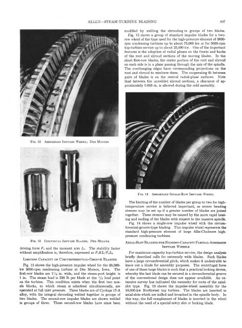
Fig. 13 shows a group of standard impulse blades for a tworow<br />
wheel of the type used for the high-pressure element of 3600-<br />
rpm condensing turbines up to about 75,000 kw or for 3600-rpm<br />
top-turbine service up to about 25,000 kw. One of the important<br />
features is the adoption of radial planes on the fronts and backs<br />
of the root and shroud sections of the moving blades. In the<br />
short first-row blades, the center portion of the root and shroud<br />
on each side is in a plane passing through the axis of the spindle.<br />
The overhanging edges have corresponding projections on the<br />
root and shroud to reinforce them. The cooperating fit between<br />
pairs of blades is on the central radial-plane surfaces. Note<br />
that between the unwelded shroud sections, a clearance of approximately<br />
0.005 in. is allowed during the cold assembly.<br />
F i q . 14<br />
A s s e m b l e d Sin g l e - R o w I m p u l s e W h e e l<br />
F i q . 13<br />
I n d iv id u a l I m p u l s e B l a d e s; D e s M o in e s<br />
driving force F, and the moment arm L\. The stability factor<br />
without amplification is, therefore, expressed as FeK L/F ,Li.<br />
L im i t i n g C a p a c it y o f C i r c u m f e r e n t ia l - G r o o v e B l a d in g<br />
Fig. 12 shows the high-pressure impulse wheel for the 35,000-<br />
kw 3600-rpm condensing turbine at Des Moines, Iowa. The<br />
first-row blades are IV 2 in- wide, and the steam-port height is<br />
1 in. The steam load is 238 lb per blade at the '/a load point<br />
on the turbine. This condition exists when the first two nozzle<br />
blocks, to which steam is admitted simultaneously, are<br />
operated at full inlet pressure. These blades are of Cyclops 17-A<br />
alloy, with the integral shrouding welded together in groups of<br />
two blades. The second-row impulse blades are shown welded<br />
in groups of three. These second-row blades have since been<br />
The limiting of the number of blades per group to two for hightemperature<br />
service is believed important, as severe bending<br />
stresses may be set up if a greater number of blades are joined<br />
together. These stresses may be caused by the more rapid heating<br />
and cooling of the blades with respect to the massive spindle.<br />
Fig. 14 shows a single-row impulse wheel with the circumferential-groove-type<br />
blading. This impulse wheel represents the<br />
standard high-pressure element of large Allis-Chalmers highpressure<br />
condensing turbines.<br />
A x i a l -S l o t B l a d in g f o r H ig h e s t -C a p a c it y P a r t ia l -A d m is s io n<br />
I m p u l s e W h e e l s<br />
For maximum-capacity top-turbine service, the design analysis<br />
briefly described calls for extremely wide blades. Such blades<br />
have a large circumferential pitch, which makes it undesirable to<br />
leave out a blade for assembly purposes. The centrifugal force<br />
of one of these large blades is such that a practical locking device,<br />
whereby the last blade can be secured in a circumferential groove<br />
of the conventional design does not appear available. An extensive<br />
survey has indicated the necessity for roots of the axialslot<br />
type. Fig. 15 shows the impulse-wheel assembly for the<br />
50,000-kw Northwest top turbine. The blades are inserted in<br />
axial slots which are milled and broached in the spindle body. In<br />
this way, the full complement of blades is inserted in the wheel<br />
without the need of a special entry slot or locking blade.


