WIRELESS ROUTER ADSL2+ - Atlantis Land
WIRELESS ROUTER ADSL2+ - Atlantis Land
WIRELESS ROUTER ADSL2+ - Atlantis Land

Create successful ePaper yourself
Turn your PDF publications into a flip-book with our unique Google optimized e-Paper software.
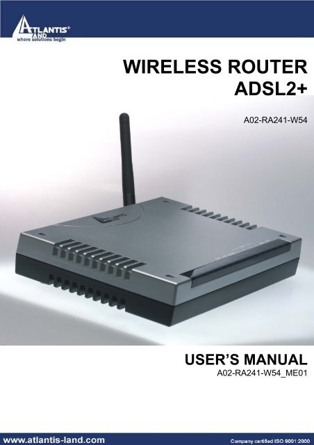
<strong>WIRELESS</strong> <strong>ROUTER</strong><br />
<strong>ADSL2+</strong><br />
A02-RA241-W54<br />
USER’S MANUAL<br />
A02-RA241-W54_ME01
<strong>WIRELESS</strong> <strong>ROUTER</strong> <strong>ADSL2+</strong><br />
Copyright<br />
The <strong>Atlantis</strong> <strong>Land</strong> logo is a registered trademark of <strong>Atlantis</strong> <strong>Land</strong> SpA. All other names<br />
mentioned mat be trademarks or registered trademarks of their respective owners. Subject to<br />
change without notice. No liability for technical errors and/or omissions.<br />
CE Mark Warning<br />
This is a Class B product. In a domestic environment, this product may cause radio<br />
interference, in which case the user may be required to take adequate measures.<br />
Important Note<br />
The antenna(s) used for this equipment must be installed to provide a separation distance of<br />
at least 30 cm from all persons.<br />
FCC Warning<br />
This equipment has been tested and found to comply with the limits for a Class B digital<br />
device, pursuant to Part 15 of the FCC Rules. These limits are designed to provide<br />
reasonable protection against harmful interference in a residential installation.<br />
This equipment generates, uses and can radiate radio frequency energy and, if not installed<br />
and used in accordance with the instructions, may cause harmful interference to radio<br />
communications. However, there is no guarantee that interference will not occur in a<br />
particular installation. If this equipment does cause harmful interference to radio or television<br />
reception, which can be determined by turning the equipment off and on, the user is<br />
encouraged to try to correct the interference by one of the following measures:<br />
• Reorient or relocate the receiving antenna.<br />
• Increase the separation between the equipment and receiver.<br />
• Connect the equipment into an outlet on a circuit different from that to which the<br />
• receiver is connected.<br />
• Consult the dealer or an experienced radio/TV technician for help.<br />
FCC Caution: To assure continued compliance, (example - use only shielded interface<br />
cables when connecting to computer or peripheral devices) any changes or modifications not<br />
expressly approved by the party responsible for compliance could void the user's authority to<br />
operate this equipment.<br />
This device complies with Part 15 of the FCC Rules. Operation is subject to the following two<br />
conditions:<br />
1) This device may not cause harmful interference, and<br />
2) This device must accept any interference received, including interference that may cause<br />
undesired operation.
<strong>WIRELESS</strong> <strong>ROUTER</strong> <strong>ADSL2+</strong><br />
TABLE OF CONTENTS<br />
CHAPTER 1 .............................................. 1<br />
1.1 AN OVERVIEW OF THE <strong>WIRELESS</strong> <strong>ROUTER</strong> <strong>ADSL2+</strong> .................................................................. 1<br />
1.2 PACKAGE CONTENTS .................................................................................................................... 2<br />
1.3 <strong>WIRELESS</strong> <strong>ROUTER</strong> <strong>ADSL2+</strong> FEATURES .................................................................................... 2<br />
1.4 <strong>WIRELESS</strong> <strong>ROUTER</strong> <strong>ADSL2+</strong> APPLICATION ................................................................................ 5<br />
CHAPTER 2 .............................................. 6<br />
2.1 CAUTIONS FOR USING THE <strong>WIRELESS</strong> <strong>ROUTER</strong> <strong>ADSL2+</strong> ........................................................... 6<br />
2.2 THE FRONT LEDS......................................................................................................................... 6<br />
2.3 THE REAR PORTS ......................................................................................................................... 7<br />
2.4 CABLING ........................................................................................................................................ 7<br />
CHAPTER 3 .............................................. 9<br />
3.1 BEFORE CONFIGURATION ............................................................................................................. 9<br />
3.2 CONNECTING THE <strong>WIRELESS</strong> <strong>ROUTER</strong> <strong>ADSL2+</strong> ......................................................................... 9<br />
3.3 CONFIGURING PC IN WINDOWS ................................................................................................. 10<br />
For Windows 95/98/ME.............................................................................................................. 10<br />
For Windows NT4.0 .................................................................................................................... 12<br />
For Windows 2000 ...................................................................................................................... 13<br />
For Windows XP.......................................................................................................................... 15<br />
3.4 FACTORY DEFAULT SETTINGS .................................................................................................... 17<br />
3.4.1 Username and Password................................................................................................. 17<br />
3.4.2 LAN and WAN Port Addresses ....................................................................................... 18<br />
3.5 INFORMATION FROM THE ISP...................................................................................................... 18<br />
3.6 CONFIGURING WITH THE WEB BROWSER................................................................................... 18<br />
3.6.1 STATUS.............................................................................................................................. 19<br />
3.6.1.1 ARP Table................................................................................................................... 19<br />
3.6.1.2 Routing Table ............................................................................................................. 20<br />
3.6.1.3 DHCP Table................................................................................................................ 20<br />
3.6.1.4 System Log ................................................................................................................. 21<br />
3.6.1.5 Security Log................................................................................................................... 21<br />
3.6.2 Quick Start Guide.............................................................................................................. 22<br />
3.6.3 CONFIGURATION............................................................................................................ 24<br />
3.6.3.1 LAN .............................................................................................................................. 24<br />
3.6.3.1.1 Ethernet................................................................................................................ 24<br />
3.6.3.1.2 Wireless................................................................................................................ 25<br />
3.6.3.1.3 Wireless Security................................................................................................ 26<br />
3.6.3.1.4 DHCP Server....................................................................................................... 28<br />
3.6.3.2 WAN............................................................................................................................. 30<br />
3.6.3.2.1 ISP ........................................................................................................................ 30<br />
3.6.3.2.2 DNS ...................................................................................................................... 34<br />
3.6.3.2.3 ADSL .................................................................................................................... 35<br />
3.6.3.3 System......................................................................................................................... 36<br />
3.6.3.3.1 Time Zone............................................................................................................ 36
<strong>WIRELESS</strong> <strong>ROUTER</strong> <strong>ADSL2+</strong><br />
3.6.3.3.2 Remote Access................................................................................................... 36<br />
3.6.3.3.3 Firmware .............................................................................................................. 37<br />
3.6.3.3.4 Backup/Restore .................................................................................................. 38<br />
3.6.3.3.5 Restart.................................................................................................................. 39<br />
3.6.3.3.6 User Management.............................................................................................. 39<br />
3.6.3.4 Firewall ........................................................................................................................ 41<br />
3.6.3.4.1 Packet Filering .................................................................................................... 41<br />
3.6.3.4.2 MAC address Filtering ....................................................................................... 48<br />
3.6.3.4.3 Intrusion Detection.............................................................................................. 49<br />
3.6.3.4.4 Block Wan Request............................................................................................ 50<br />
3.6.3.4.5 URL Blocking....................................................................................................... 50<br />
3.6.3.5 QoS .............................................................................................................................. 53<br />
3.6.3.6 Virtual Server.............................................................................................................. 65<br />
3.6.3.7 Advanced .................................................................................................................... 67<br />
3.6.3.7.1 Static Routed....................................................................................................... 67<br />
3.6.3.7.2 Dynamic DNS...................................................................................................... 68<br />
3.6.3.7.3 VLAN .................................................................................................................... 69<br />
3.6.3.7.4 Device Management .......................................................................................... 70<br />
3.6.3.7.5 IGMP..................................................................................................................... 72<br />
3.6.4 SAVE Config ...................................................................................................................... 73<br />
CHAPTER 4 ............................................ 73<br />
PROBLEMS STARTING UP THE <strong>WIRELESS</strong> ADSL <strong>ROUTER</strong> .............................................................. 73<br />
PROBLEMS WITH THE WAN INTERFACE............................................................................................ 74<br />
PROBLEMS WITH THE LAN INTERFACE ............................................................................................. 74<br />
APPENDIX A........................................... 75<br />
<strong>WIRELESS</strong> LAN OVERVIEW............................................................................................................... 75<br />
APPENDIX B........................................... 78<br />
TRAFFIC SHAPING.............................................................................................................................. 78<br />
APPENDIX C........................................... 79<br />
TECHNICAL FEATURES....................................................................................................................... 79<br />
APPENDIX D........................................... 80<br />
SUPPORT............................................................................................................................................ 80<br />
A02-RA241-W54_ME01 (June 2005, V1.00)
<strong>WIRELESS</strong> <strong>ROUTER</strong> <strong>ADSL2+</strong><br />
Chapter 1<br />
Introduction<br />
1.1 An Overview of the Wireless Router <strong>ADSL2+</strong><br />
Broadband Sharing and IP sharing<br />
The Compact Router <strong>ADSL2+</strong> supports 4 x 10/100 Mbps auto-negotiating Fast Ethernet<br />
ports for connection to your PC or LAN and downstream (with built-in <strong>ADSL2+</strong> modem) rate<br />
up to 24Mbps. Power by NAT technology, dozens of network users can surf on the Internet<br />
and share the ADSL connection simultaneously by using one ISP account and one single IP<br />
address.<br />
Wireless<br />
With integrated IEEE802.11g Wireless Access Point (up to 54Mbps), the device offers quick<br />
and easy access among wired network and wireless network. The Wireless Router also<br />
supports WPA security, it increases the level of data protection and access control for<br />
Wireless LAN.<br />
Security: Firewall & VLAN<br />
This product also serves as an Internet firewall, protecting your network from being accessed<br />
by outside users. Not only provide the natural firewall function (Network Address Translation,<br />
NAT), it also provides rich firewall features to secure user's network.<br />
The VLANs allow to segment the traffic of net and, in this way, they improve management<br />
and performance of entire network.<br />
Quality of Service and IP Throttling<br />
QoS gives you full control over which types of outgoing data traffic should be given priority by<br />
the router, ensuring important data like gaming packets move through the router at lightning<br />
speed, even under heavy load.<br />
Using IP Throttling, bandwidth limits can be enforced on any system within your LAN, or even<br />
on a particular application.<br />
Easy Configuration and Management<br />
Support web based GUI and Telnet for configuration and management. Also supports remote<br />
management (Web and telnet) capability for remote user to configure and manage this<br />
product. It incorporates besides a client Dynamic DNS.<br />
1
1.2 Package Contents<br />
• Wireless Router <strong>ADSL2+</strong><br />
• One CD-ROM containing the online manual<br />
• One Quick Start Guide<br />
• One RJ-11 ADSL/telephone cable<br />
• One CAT-5 LAN cable<br />
• One AC-DC power adapter (12VDC, 1A)<br />
If any of the above items are missing, please contact your reseller.<br />
<strong>WIRELESS</strong> <strong>ROUTER</strong> <strong>ADSL2+</strong><br />
1.3 Wireless Router <strong>ADSL2+</strong> Features<br />
Wireless ADSL Router2+ provides the following features:<br />
• ADSL Multi-Mode Standard: Supports downstream transmission rates of up to<br />
8Mbps and upstream transmission rates of up to 1024Kbps. It also supports rate<br />
management that allows ADSL subscribers to select an Internet access speed suiting<br />
their needs and budgets. It is compliant with Multi-Mode standard (ANSI T1.413,<br />
Issue 2; G.dmt (G.992.1); G.lite (G992.2); G.hs(G994.1); G.dmt.bis(ITU G.992.3);<br />
Gdmt.bisplus(ITU G.992.5)].<br />
• Fast Ethernet Switch: A 4-port 10/100Mbps fast Ethernet switch is supported in the<br />
LAN site and automatic switching between MDI and MDI-X for 10Base-T and<br />
100Base-TX ports is supported. An Ethernet straight or cross-over cable can be used<br />
directly, this fast Ethernet switch will detect it automatically.<br />
• Wireless Ethernet 802.11g: With built-in 802.11g access point for extending the<br />
communication media to WLAN while providing the WEP and WPA for securing your<br />
wireless networks.<br />
• Multi-Protocol to Establish A Connection: Supports PPPoA (RFC 2364 - PPP over<br />
ATM Adaptation Layer 5), RFC 1483 encapsulation over ATM (bridged or routed),<br />
PPP over Ethernet (RFC 2516), and IPoA (RFC1577) to establish a connection with<br />
the ISP. The product also supports VC-based and LLC-based multiplexing.<br />
• Quick Installation Wizard: Supports a WEB GUI page to install this device quickly.<br />
With this wizard, an end user can enter the information easily which they from the ISP,<br />
then surf the Internet immediately.<br />
• Universal Plug and Play (UPnP) and UPnP NAT Traversal: This protocol is used to<br />
enable simple and robust connectivity among stand-alone devices and PCs from<br />
many different vendors. It makes network simple and affordable for users. UPnP<br />
architecture leverages TCP/IP and the Web to enable seamless proximity networking<br />
in addition to control and data transfer among networked devices.<br />
• Network Address Translation (NAT): Allows multi-users to access outside resource<br />
such as Internet simultaneously with one IP address/one Internet access account.<br />
Besides, many application layer gateway (ALG) are supported such as web browser,<br />
ICQ, FTP, Telnet, E-mail, News, Net2phone, Ping, NetMeeting and others.<br />
2
<strong>WIRELESS</strong> <strong>ROUTER</strong> <strong>ADSL2+</strong><br />
• Firewall: Supports SOHO firewall with NAT technology. Automatically detects and<br />
blocks the Denial of Service (DoS) attack. The URL-blocking, packet filtering are also<br />
supported. The hacker’s attack will be recorded associated with timestamp in the<br />
security logging area. More firewall features will be added continually, please visit our<br />
web site to download latest firmware.<br />
• VLAN: A VLAN is a group of end-stations that are not constrained by their physical<br />
location and can communicate as if a common broadcast domain, a LAN. The primary<br />
utility of using VLAN is to reduce latency and need for routers, using faster switching<br />
instead. Other VLAN utility includes:<br />
• Security, Security is increased with the reduction of opportunity in<br />
eavesdropping on a broadcast network because data will be switched to<br />
only those confidential users within the VLAN.<br />
• Cost Reduction, VLANs can be used to create multiple broadcast domains,<br />
thus eliminating the need of expensive routers.<br />
• Port-based (or port-group) VLAN is the common method of implementing a<br />
VLAN, and is the one supplied in the Switch.<br />
• QoS: QoS gives you full control over which types of outgoing data traffic should be<br />
given priority by the Router, ensuring important data like gaming packets move<br />
through the Router at lightning speed, even under heavy load.<br />
• Domain Name System (DNS) relay: provides an easy way to map the domain name<br />
(a friendly name for users such as www.yahoo.com) and IP address. When a local<br />
machine sets its DNS server with this router’s IP address, then every DNS conversion<br />
requests packet from the PC to this router will be forwarded to the real DNS in the<br />
outside network. After the router gets the reply, then forwards it back to the PC.<br />
• Dynamic Domain Name System (DDNS): The Dynamic DNS service allows you to<br />
alias a dynamic IP address to a static hostname. This dynamic IP address is the WAN<br />
IP address. For example, to use the service, you must first apply an account from this<br />
free Web server http://www.dyndns.org/. There are more than 5 DDNS servers<br />
supported.<br />
• PPP over Ethernet (PPPoE): Provide embedded PPPoE client function to establish a<br />
connection. Users can get greater access speed without changing the operation<br />
concept, sharing the same ISP account and paying for one access account. No<br />
PPPoE client software is required for the local computer. The Always ON, Dial On<br />
Demand and auto disconnection (Idle Timer) functions are provided too.<br />
• Virtual Server: Users can specify some services to be visible from outside users. The<br />
router can detect incoming service request and forward it to the specific local<br />
computer to handle it. For example, users can assign a PC in a LAN acting as a WEB<br />
server inside and expose it to the outside network. Outside users can browse an<br />
inside web server directly while it is protected by NAT. A DMZ host setting is also<br />
provided to a local computer exposed to the outside network, Internet<br />
• Rich Packet Filtering: Not only filters the packet based on IP address, but also based<br />
on Port numbers. It also provides a higher-level security control.<br />
3
<strong>WIRELESS</strong> <strong>ROUTER</strong> <strong>ADSL2+</strong><br />
• Dynamic Host Control Protocol (DHCP) client and server: In the WAN site, the<br />
DHCP client can get an IP address from the Internet Server Provider (ISP)<br />
automatically. In the LAN site, the DHCP server can allocate up to 253 client IP<br />
addresses and distribute them including IP address, subnet mask as well as DNS IP<br />
address to local computers. It provides an easy way to manage the local IP network.<br />
• Static and RIP1/2 Routing: Supports an easy static table or RIP1/2 routing protocol<br />
to support routing capability.<br />
• SNTP: An easy way to get the network real time information from an SNTP server.<br />
• SNMP: SNMP is an application layer protocol that is used for managing networks<br />
(V1,V2 and V3)<br />
• Web based GUI: supports web based GUI for configuration and management. It is<br />
user-friendly with an on-line help, providing necessary information and assist user<br />
timing. It also supports remote management capability for remote users to configure<br />
and manage this product.<br />
• Firmware Upgradeable: the device can be upgraded to the latest firmware through<br />
the WEB based GUI.<br />
• Rich management interfaces: Supports flexible management interfaces with local<br />
console port, LAN port, and WAN port. Users can use terminal application through<br />
console port to configure and manage the device, or Telnet, WEB GUI, and SNMP<br />
through LAN or WAN ports to configure and manage a device.<br />
4
1.4 Wireless Router <strong>ADSL2+</strong> Application<br />
<strong>WIRELESS</strong> <strong>ROUTER</strong> <strong>ADSL2+</strong><br />
5
<strong>WIRELESS</strong> <strong>ROUTER</strong> <strong>ADSL2+</strong><br />
Chapter 2<br />
Using Wireless Router <strong>ADSL2+</strong><br />
2.1 Cautions for using the Wireless Router <strong>ADSL2+</strong><br />
Do not place the Wireless Router <strong>ADSL2+</strong> under high humidity and high<br />
temperature.<br />
Do not use the same power source for Wireless Router <strong>ADSL2+</strong> with other<br />
equipment.<br />
Do not open or repair the case yourself. If the Wireless Router <strong>ADSL2+</strong> is<br />
too hot, turn off the power immediately and have a qualified serviceman repair<br />
it.<br />
Place the Wireless Router <strong>ADSL2+</strong> on a stable surface.<br />
Only use the power adapter that comes with the package.<br />
Do NOT upgrade firmware on any <strong>Atlantis</strong> <strong>Land</strong> product over a wireless<br />
connection.<br />
Failure of the device may result. Use only hard-wired network connections.<br />
2.2 The Front LEDs<br />
LED<br />
POWER(5)<br />
SYS(6)<br />
WLAN/7)<br />
LAN (8-11)<br />
ADSL(12)<br />
PPP(13)<br />
Meaning<br />
Lit when power ON.<br />
Lit when system is ready.<br />
Flashes green when the wireless connection is<br />
established. Flashes when sending/receiving data.<br />
Lit when connected to Ethernet device<br />
Green for 100Mbps; Orange for 10Mbps<br />
Blinking when data transmit/received.<br />
Lit when successfully connected to an ADSL DSLAM.<br />
Steady glow when there is a PPPoA / PPPoE connection.<br />
6
2.3 The Rear Ports<br />
<strong>WIRELESS</strong> <strong>ROUTER</strong> <strong>ADSL2+</strong><br />
LINE<br />
(RJ-11)<br />
PORT<br />
LAN<br />
(4 *RJ-45)*<br />
RESET<br />
POWER (Jack)<br />
POWER Switch<br />
Meaning<br />
Connect the supplied RJ-11 cable to this<br />
port when connecting to the<br />
ADSL/telephone network.<br />
Connect an UTP Ethernet cable to one of<br />
the four LAN ports when connecting to a<br />
PC or an office/home network of 10Mbps<br />
or 100Mbps.<br />
Recovery procedures for a lost web<br />
interface password:<br />
After turning the router on press the<br />
Emergency/Failure Recovery Button on<br />
the back of the modem, and hold the<br />
button in until all lights on the modem flash<br />
and it reboots with factory default settings.<br />
The login will be reset to admin and the<br />
password will be reset to admin, and the<br />
modem will be accessible via its default IP<br />
address at http://192.168.1.254/<br />
This is used when you can not login to the<br />
router, e.g. forgot the password)<br />
Connect the supplied power adapter to this<br />
jack.<br />
A Power ON/OFF switch<br />
2.4 Cabling<br />
The most common problem is bad cabling or ADSL line. Make sure that all connected<br />
devices are turned on. On the front of the product is a bank of LEDs. As a first check, verify<br />
that the LAN Link, ADSL , PWR, SYS LEDs are lit and WLAN is blanking. If they are not,<br />
verify that you are using the proper cables.<br />
Ensure that all other devices connected to the same telephone line as your router (e.g.<br />
telephones, fax machines, analog modems) have a line filter (A01-AF2) connected between<br />
them and the wall socket (unless you are using a Central Splitter or Central Filter installed by<br />
7
<strong>WIRELESS</strong> <strong>ROUTER</strong> <strong>ADSL2+</strong><br />
a qualified and licensed electrician), and ensure that all line filters are correctly installed and<br />
the right way around.<br />
Missing line filters or line filters installed the wrong way around can<br />
cause problems with your ADSL connection, including frequent<br />
disconnections.<br />
8
<strong>WIRELESS</strong> <strong>ROUTER</strong> <strong>ADSL2+</strong><br />
Chapter 3<br />
Configuration<br />
The Wireless Router <strong>ADSL2+</strong> can be configured with your Web browser. The web browser<br />
is included as a standard application in the following operation systems, UNIX, Linux, Mac<br />
OS, Windows 95/98/NT/2000/Me, and etc. The product provides a very easy and userfriendly<br />
interface for configuration.<br />
3.1 Before Configuration<br />
This section describes the configuration required by LAN-attached PCs that communicate<br />
with the Wireless Router <strong>ADSL2+</strong>, either to configure the device or for network access.<br />
These PCs must have an Ethernet interface (or wireless adapter) installed properly, be<br />
connected to the ADSL Wireless Router either directly or through an external repeater hub,<br />
and have TCP/IP installed and configured to obtain an IP address through a DHCP server or<br />
a fixed IP address that must be in the same subnet of the ADSL Firewall Router. The default<br />
IP address of the Wireless Router <strong>ADSL2+</strong> is 192.168.1.254 and subnet mask is<br />
255.255.255.0. The best and easy way is to configure the PC to get an IP address from the<br />
Wireless Router <strong>ADSL2+</strong>. Also make sure you have UNINSTALLED any kind of software<br />
firewall that can cause problems while accessing the 192.168.1.254 IP address of the router.<br />
Please follow the steps below for PC’s network environment installation. First of all, please<br />
check your PC’s network components. The TCP/IP protocol stack and Ethernet network<br />
adapter must be installed. If not, please refer to MS Windows related manuals.<br />
Any TCP/IP capable workstation can be used to communicate with or<br />
through the Wireless Router <strong>ADSL2+</strong>. To configure other types of<br />
workstations, please consult the manufacturer’s documentation.<br />
3.2 Connecting the Wireless Router <strong>ADSL2+</strong><br />
• Connect the Wireless Router <strong>ADSL2+</strong> to a LAN (Local Area Network) and the<br />
ADSL/telephone network.<br />
• Power on the device<br />
• Make sure the PWR (WLAN LED is blinking) is lit steady & LAN/ADSL LED is lit.<br />
• Before taking the next step, make sure you have uninstalled any software firewall.<br />
9
3.3 Configuring PC in Windows<br />
For Windows 95/98/ME<br />
<strong>WIRELESS</strong> <strong>ROUTER</strong> <strong>ADSL2+</strong><br />
1. Go to Start / Settings / Control Panel. In the Control Panel, double-click on<br />
Network and choose the Configuration tab.<br />
2. Select TCP / IP -> NE2000 Compatible, or the name of any Network Interface Card<br />
(NIC) in your PC.<br />
3. Click Properties.<br />
4. Select the IP Address tab. In this page, click the Obtain an IP address<br />
automatically radio button.<br />
10
<strong>WIRELESS</strong> <strong>ROUTER</strong> <strong>ADSL2+</strong><br />
5. Then select the DNS Configuration tab.<br />
6. Select the Disable DNS radio button and click “OK” to finish the configuration.<br />
11
For Windows NT4.0<br />
<strong>WIRELESS</strong> <strong>ROUTER</strong> <strong>ADSL2+</strong><br />
1. Go to Start / Settings / Control Panel. In the Control Panel, double-click on<br />
Network and choose the Protocols tab.<br />
2. Select TCP/IP Protocol and click Properties.<br />
3. Select the Obtain an IP address from a DHCP server radio button and click<br />
“OK”.<br />
12
<strong>WIRELESS</strong> <strong>ROUTER</strong> <strong>ADSL2+</strong><br />
For Windows 2000<br />
1. Go to Start / Settings / Control Panel. In the Control Panel, double-click on<br />
Network and Dial-up Connections.<br />
2. Double-click LAN Area Connection.<br />
3. In the LAN Area Connection Status window, click Properties.<br />
13
<strong>WIRELESS</strong> <strong>ROUTER</strong> <strong>ADSL2+</strong><br />
4. Select Internet Protocol (TCP/IP) and click Properties.<br />
5. Select the Obtain an IP address automatically and the Obtain DNS server<br />
address automatically radio buttons.<br />
6. Click “OK” to finish the configuration.<br />
14
<strong>WIRELESS</strong> <strong>ROUTER</strong> <strong>ADSL2+</strong><br />
For Windows XP<br />
1. Go to Start / Control Panel (in Classic View). In the Control Panel, double-click on<br />
Network Connections.<br />
2. Double-click Local Area Connection<br />
3. In the LAN Area Connection Status window, click Properties.<br />
15
<strong>WIRELESS</strong> <strong>ROUTER</strong> <strong>ADSL2+</strong><br />
4. Select Internet Protocol (TCP/IP) and click Properties.<br />
5. Select the Obtain an IP address automatically and the Obtain DNS server<br />
address automatically radio buttons<br />
6. Click “OK” to finish the configuration.<br />
16
<strong>WIRELESS</strong> <strong>ROUTER</strong> <strong>ADSL2+</strong><br />
3.4 Factory Default Settings<br />
Before configurating this Wireless Router <strong>ADSL2+</strong>, you need to know the following default<br />
settings.<br />
• Username: admin<br />
• Password : atlantis<br />
• IP Address : 192.168.1.254<br />
• Subnet Mask : 255.255.255.0<br />
• DHCP server is enabled.<br />
• Wireless: SSSID= wlan-ap, Channel=6, WEP=disable<br />
3.4.1 Username and Password<br />
The default username and password are admin and atlantis respectively.<br />
If you ever forget the password to log in, you may press the RESET button to<br />
restore the factory default settings. After turning the router on press the<br />
Emergency/Failure Recovery Button on the back of the modem, and hold the<br />
button in until all lights on the modem flash and it reboots with factory default<br />
settings. The login will be reset to admin and the password will be reset to<br />
admin, and the modem will be accessible via its default IP address at<br />
http://192.168.1.254/<br />
17
<strong>WIRELESS</strong> <strong>ROUTER</strong> <strong>ADSL2+</strong><br />
3.4.2 LAN and WAN Port Addresses<br />
The parameters of LAN and WAN ports are pre-set in the factory. The default values are<br />
shown below.<br />
LAN Port<br />
IP address<br />
Subnet Mask<br />
DHCP<br />
function<br />
server<br />
192.168.1.254<br />
255.255.255.0<br />
Enabled<br />
3.5 Information from the ISP<br />
WAN Port<br />
Before configuring this device, you have to check with your ISP (Internet Service Provider)<br />
what kind of service is provided such as PPPoE, PPPoA, RFC1483, IpoA.<br />
Gather the information as illustrated in the following table and keep it for reference.<br />
PPPoE<br />
VPI/VCI, VC-based/LLC-based multiplexing, Username,<br />
Password, Service Name, and Domain Name System<br />
(DNS) IP address (it can be automatically assigned from<br />
ISP or be set fixed).<br />
PPPoA<br />
VPI/VCI, VC-based/LLC-based multiplexing, Username,<br />
Password, and Domain Name System (DNS) IP<br />
address (it can be automatically assigned from ISP or<br />
be set fixed).<br />
RFC1483 Bridged VPI/VCI, VC-based/LLC-based multiplexing and configure<br />
this product into BRIDGE Mode.<br />
RFC1483 Routed VPI/VCI, VC-based/LLC-based multiplexing, IP address,<br />
Subnet mask, Gateway address, and Domain Name<br />
System (DNS) IP address (it is fixed IP address).<br />
IPoA<br />
VPI/VCI, IP address, Subnet mask, Gateway address,<br />
and Domain Name System (DNS) IP address (it is fixed<br />
IP address).<br />
3.6 Configuring with the Web Browser<br />
Open the web browser, enter the local port IP address of this Wireless Router <strong>ADSL2+</strong>,<br />
which defaults at http://192.168.1.254, and click “Go”, a username and password window<br />
will appear. The default username & password are admin & atlantis, in respectively<br />
N/A<br />
18
<strong>WIRELESS</strong> <strong>ROUTER</strong> <strong>ADSL2+</strong><br />
You will get a status report web page when login successfully.<br />
At the configuration homepage, the left navigation page where bookmarks are provided links<br />
you directly to the desired setup page, including:<br />
• Status (ADSL, LAN, PPP, VPN connect Status, Learned MAC Table, Routing<br />
Table, System Log, Security Log)<br />
• Quick Start<br />
• Configuration (WAN, LAN, Wireless, System, Firewall, VPN, Virtual Server,<br />
Advanced)<br />
• Save Config<br />
Click on the desired item to expand the page in the main navigation page.<br />
3.6.1 STATUS<br />
The Status section provides and contains many items including device H/W and S/W<br />
information, LAN, WAN, Port status and all defined interfaces. It also provides useful<br />
information for users to review the status of device.<br />
Click on Status will open all the following subsections:<br />
• ARP Table<br />
• Routing Table<br />
• DHCP Table<br />
• System Log<br />
• Security Log<br />
3.6.1.1 ARP Table<br />
The router’s ARP (Address Resolution Protocol) Table shows the mapping of Internet (IP)<br />
addresses to Ethernet (MAC) addresses. This is a quick way to determine the MAC address<br />
of the network interface of your PCs to use with the router’s Firewall – MAC Address Filter<br />
function. See the Firewall section of this manual for more information.<br />
19
<strong>WIRELESS</strong> <strong>ROUTER</strong> <strong>ADSL2+</strong><br />
• IP Address: A list of IP addresses of devices on your LAN (Local Area Network).<br />
• MAC Address: MAC (Media Access Control) address for each device on your LAN.<br />
• Interface: The interface name (on the router) that this IP Address connects to.<br />
• Static: Static status of the ARP table entry:<br />
• “no” for dynamically-generated ARP table entries<br />
• “yes” for static ARP table entries added by the user<br />
3.6.1.2 Routing Table<br />
Display the current routing paths of A02-RA241-W54.<br />
• #: Item number<br />
• Destination: IP address of the destination network.<br />
• Netmask: The destination netmask address.<br />
• Gateway/Interface: IP address of the gateway or existing interface that this route<br />
uses.<br />
• Cost: The cost of transmission for routing purposes. The number need not be precise,<br />
but it must be between 0 and 65535.<br />
• Interface: Select the interface through which packets are forwarded.<br />
3.6.1.3 DHCP Table<br />
20
<strong>WIRELESS</strong> <strong>ROUTER</strong> <strong>ADSL2+</strong><br />
• Leased: DHCP assigned IP addresses information.<br />
• IP Address: IP addresses of devices on your LAN (Local Area Network).<br />
• MAC Address: The MAC Address that you want to assign the fixed IP address<br />
• Client Host Name: Expired IP addresses information<br />
• Register Time: Register time information<br />
3.6.1.4 System Log<br />
Display the system logs cumulated till the present time. You can trace the historical<br />
information through this function.<br />
3.6.1.5 Security Log<br />
Display the information of security logs. If hacker attacks your sever, he will be isolated by<br />
the firewall function and the router will record related information. Hence, you know where<br />
the hacker comes from.<br />
21
<strong>WIRELESS</strong> <strong>ROUTER</strong> <strong>ADSL2+</strong><br />
3.6.2 Quick Start Guide<br />
For detailed instructions on configuring WAN settings, see the WAN section of this manual.<br />
The information you need for the Quick Start wizard to get you online are your login (often in<br />
the form of username@ispname), your password, and the encapsulation type.<br />
Your ISP can supply all the details you need. Alternatively, if you have deleted the current<br />
WAN Connection in the WAN – ISP section of the interface, you can use the router’s PVC<br />
Scan feature to determine the Encapsulation types offered by your ISP.<br />
Connection<br />
Encapsulation: Select the encapsulation type your ISP uses or choose “Auto Scan”.<br />
Click Start to begin scanning for encapsulation types offered by your ISP. If the scan is<br />
successful, you are presented with a list of supported options.<br />
• VCI: Enter the VCI assigned to you. This field may already be configured.<br />
• VPI: Enter the VPI assigned to you. This field may already be configured.<br />
22
• NAT: Select “Enabled”.<br />
<strong>WIRELESS</strong> <strong>ROUTER</strong> <strong>ADSL2+</strong><br />
Optional Setting<br />
• IP Address: Type your ISP assigned IP address in the IP Address text box.<br />
• Subnet Mask: Enter a subnet mask in dotted decimal notation.<br />
• Default Gateway: You must specify a gateway IP address (supplied by your ISP)<br />
DNS<br />
• Obtain DNS automatically: Select this check box to use DNS.<br />
• Primary DNS: Enter the IP addresses of the DNS servers. The DNS servers are<br />
passed to the DHCP clients along with the IP address and the subnet mask.<br />
• Secondary DNS: Enter the IP addresses of the DNS servers. The DNS servers are<br />
passed to the DHCP clients along with the IP address and the subnet mask.<br />
PPP<br />
• Username: Enter the username provided by your ISP. You can input up to 128<br />
alphanumeric characters (case sensitive). This is usually in the format of<br />
“username@ispname” instead of simply “username”.<br />
• Password: Enter the password provided by your ISP. You can input up to 128<br />
alphanumeric characters (case sensitive).<br />
Press Apply and then click on Save Config.<br />
23
<strong>WIRELESS</strong> <strong>ROUTER</strong> <strong>ADSL2+</strong><br />
3.6.3 CONFIGURATION<br />
When you click this item, you get following sub-items to configure Wireless Router <strong>ADSL2+</strong>:<br />
• LAN<br />
• WAN<br />
• System<br />
• Firewall<br />
• QoS<br />
• Virtual Server<br />
• Advanced<br />
3.6.3.1 LAN<br />
A Local Area Network (LAN) is a shared communication system to which many computers<br />
are attached and is limited to the immediate area, usually the same building or floor of a<br />
building.<br />
There are four items within the LAN section: Ethernet Wireless, Wireless Security and<br />
DHCP Server.<br />
3.6.3.1.1 Ethernet<br />
The router supports two Ethernet IP addresses in the LAN, and two different LAN subnets<br />
through which you can access the Internet at the same time. Users usually only have one<br />
subnet in their LAN, so there is no need to configure a Secondary IP address. The default IP<br />
address for the router is 192.168.1.254.<br />
RIP: RIP v1, RIP v2, RIP v1+v2 and RIP v2 Multicast.<br />
The Subnet mask of the Secondary IP Address depends on the setting of<br />
the Primary IP Address.<br />
24
3.6.3.1.2 Wireless<br />
<strong>WIRELESS</strong> <strong>ROUTER</strong> <strong>ADSL2+</strong><br />
• Mode: 802.11b + g (Mixed mode), 802.11b and 802.11g. The factory default is<br />
802.11b + g.<br />
• ESSID: Enter the unique ID given to the Access Point (AP), which is already built-in to<br />
the router’s wireless interface. To connect to this device, your wireless clients must<br />
have the same ESSID as the device.<br />
• Regulation Domain: There are five Regulation Domains for you to choose from,<br />
including North America (N.America), Europe, France, etc. The Channel ID will be<br />
different based on this setting.<br />
• Channel ID: Select the ID channel that you would like to use.<br />
• MAC Address: The AP’s MAC Address<br />
• AP Version: The Access Point firmware version.<br />
• WDS Service:<br />
WDS (Wireless Distribution System) uses wireless media to communicate with other<br />
APs. It is able to extend the effective range and coverage of the wireless network.<br />
Please make sure the SSID is the same as that AP you want to extend. Wireless LAN<br />
is Half Duplex, so one transaction pass-through 2 wireless its real data-rate will be<br />
half of normal one. In figure an example of configuration.<br />
25
<strong>WIRELESS</strong> <strong>ROUTER</strong> <strong>ADSL2+</strong><br />
You must make sure that the SSID, Encryption and Channel is set the<br />
same as that AP you wish to connect. When WDS is enable only WEP<br />
ecryption is supported.<br />
The range of radio frequencies used by IEEE 802.11b wireless devices is<br />
called a “channel”. Channels available depend on your geographical area.<br />
You may have a choice of channels (for your region) so you should use a<br />
different channel than an adjacent AP (access point) to reduce<br />
interference. Interference occurs when radio signals from different access<br />
points overlap causing interference and degrading performance.<br />
Adjacent channels partially overlap however. To avoid interference due to<br />
overlap, your AP should be on a channel at least five channels away from a<br />
channel that an adjacent AP is using. For example, if your region has 11<br />
channels and an adjacent AP is using channel 1, then you need to select a<br />
channel between 6 or 11.<br />
Please use A02-AP-W54 toextende wireless coverage.<br />
3.6.3.1.3 Wireless Security<br />
You can disable or enable with WPA or WEP for protecting wireless network.<br />
The default mode of wireless security is disabled.<br />
26
WPA Pre-Shared Key:<br />
<strong>WIRELESS</strong> <strong>ROUTER</strong> <strong>ADSL2+</strong><br />
• WPA Algorithms: TKIP (Temporal Key Integrity Protocol) utilizes a stronger<br />
encryption method and incorporates Message Integrity Code (MIC) to provide<br />
protection against hackers.<br />
• WPA Shared Key: The key for network authentication. The input format is in<br />
character style and key size should be in the range between 8 and 63 characters.<br />
• Group Key Renewal: The period of renewal time for changing the security key<br />
automatically between wireless client and Access Point (AP).<br />
• Hide ESSID: User can select Enable or Disable to hide ESSID.<br />
WEP:<br />
• WEP Encryption: To prevent unauthorized wireless stations from accessing data<br />
transmitted over the network, the router offers highly secure data encryption, known<br />
as WEP. If you require high security for transmissions, there are two alternatives to<br />
select from: WEP 64 and WEP 128. WEP 128 will offer increased security over WEP<br />
64.<br />
• Passphrase: This is used to generate WEP keys automatically based upon the input<br />
string and a pre-defined algorithm in WEP64 or WEP128. You can input the same<br />
string in both the AP and Client card settings to generate the same WEP keys. Please<br />
27
<strong>WIRELESS</strong> <strong>ROUTER</strong> <strong>ADSL2+</strong><br />
note that you do not have to enter Key (1-4) as below when the Passphrase is<br />
enabled..<br />
• Key (1-4): Enter the key to encrypt wireless data. To allow encrypted data<br />
transmission, the WEP Encryption Key values on all wireless stations must be the<br />
same as the router. There are four keys for your selection. The input format is in HEX<br />
style, 5 and 13 HEX codes are required for WEP64 and WEP128 respectively, the<br />
separator is “-“. For example, using WEP64, 11-22-33-44-55 is a valid key, whilst<br />
1122334455 is invalid.<br />
• Hide ESSID: User can select Enable or Disable to hide ESSID.<br />
3.6.3.1.4 DHCP Server<br />
You can disable or enable the DHCP (Dynamic Host Configuration Protocol) server or enable<br />
the router’s DHCP relay functions. The DHCP protocol allows your router to dynamically<br />
assign IP addresses to PCs on your network if they are configured to obtain IP addresses<br />
automatically.<br />
To disable the router’s DHCP Server, check Disabled and click Next then click Apply. When<br />
the DHCP Server is disabled you need to manually assign a fixed IP address to each PC on<br />
your network, and set the default gateway for each PC to the IP address of the router (the<br />
default is 192.168.1.254).<br />
To configure the router’s DHCP Server, check DHCP Server and click Next. You can then<br />
configure parameters of the DHCP Server including the IP pool (starting IP address and<br />
ending IP address to be allocated to PCs on your network), lease time for each assigned IP<br />
address (the period of time the IP address assigned will be valid), DNS IP address and the<br />
gateway IP address. These details are sent to the DHCP client (i.e. your PC) when it<br />
requests an IP address from the DHCP server. Click Apply to enable this function. If you<br />
check “Use Router as a DNS Server”, the ADSL Router performs the domain name lookup,<br />
finds the IP address from the outside network automatically and forwards it back to the<br />
requesting PC in the LAN (your Local Area Network).<br />
28
<strong>WIRELESS</strong> <strong>ROUTER</strong> <strong>ADSL2+</strong><br />
If you check DHCP Relay Agent and click Next then you must enter the IP address of the<br />
DHCP server which assigns an IP address back to the DHCP client in the LAN. Use this<br />
function only if advised to do so by your network administrator or ISP. Click Apply to enable<br />
this function.<br />
29
<strong>WIRELESS</strong> <strong>ROUTER</strong> <strong>ADSL2+</strong><br />
3.6.3.2 WAN<br />
Before you start installing this device, you have to check with your ISP what kind of service<br />
(connection method) is provided such as PPPoE, PPPoA, RFC1483 bridged or routed, IPoA.<br />
Gather the information as illustrated in the following table and keep it for reference.<br />
PPPoE<br />
VPI/VCI, VC-based/LLC-based multiplexing,<br />
Username, Password, Service Name, and<br />
Domain Name System (DNS) IP address (it can<br />
be automatically assigned from ISP or be set<br />
fixed).<br />
PPPoA<br />
RFC1483<br />
Bridged<br />
RFC1483<br />
Routed<br />
IPoA<br />
VPI/VCI, VC-based/LLC-based multiplexing,<br />
Username, Password, and Domain Name<br />
System (DNS) IP address (it can be<br />
automatically assigned from ISP or be set<br />
fixed).<br />
VPI/VCI, VC-based/LLC-based multiplexing<br />
VPI/VCI, VC-based/LLC-based multiplexing, IP<br />
address, Subnet mask, Gateway address, and<br />
Domain Name System (DNS) IP address (it is<br />
fixed IP address).<br />
VPI/VCI, IP address, Subnet mask, Gateway<br />
address, and Domain Name System (DNS) IP<br />
address (it is fixed IP address).<br />
A WAN (Wide Area Network) is an outside connection to another network or the Internet.<br />
There are three items within the WAN section: ISP, DNS and ADSL.<br />
3.6.3.2.1 ISP<br />
The factory default is PPPoE. If your ISP uses this access protocol, click Edit to input other<br />
parameters as below. If your ISP does not use PPPoE, you can change the default WAN<br />
connection entry by clicking Change.<br />
A simpler alternative is to select Quick Start from the main menu on the left. See the Quick<br />
Start section of the manual for more information.<br />
Click Next in order to finish the configuration.<br />
30
<strong>WIRELESS</strong> <strong>ROUTER</strong> <strong>ADSL2+</strong><br />
PPPoE(RFC 2516) or PPPoA(RFC 2364)<br />
PPPoE (PPP over Ethernet) provides access control in a manner similar to dial-up services<br />
using PPP.<br />
PPPoA stands for Point to Point Protocol over ATM Adaptation Layer 5 (AAL5). It provides<br />
access control and billing functionality in a manner similar to dial-up services using PPP.<br />
• Description: A user-definable name for this connection.<br />
• VPI/VCI: Enter the information provided by your ISP.<br />
• NAT: The NAT (Network Address Translation) feature allows multiple users to access<br />
the Internet through a single ISP account, sharing a single IP address. If users on your<br />
LAN have public IP addresses and can access the Internet directly, the NAT function<br />
can be disabled.<br />
• Username: Enter the username provided by your ISP. You can input up to 128<br />
alphanumeric characters (case sensitive). This is in the format of<br />
“username@ispname” instead of simply “username”.<br />
• Password: Enter the password provided by your ISP. You can input up to 128<br />
alphanumeric characters (case sensitive).<br />
• Service Name: This item is for identification purposes. If it is required, your ISP<br />
provides you the information. Maximum input is 20 alphanumeric characters.<br />
• IP Address: Your WAN IP address. Leave this at 0.0.0.0 to automatically obtain an IP<br />
address from your ISP.<br />
• Authentication Protocol: Default is Chap. Your ISP advises on using Chap or Pap.<br />
• Connection:<br />
• Always on: If you want the router to establish a PPPoE session when starting<br />
up and to automatically re-establish the PPPoE session when disconnected by<br />
the ISP.<br />
31
<strong>WIRELESS</strong> <strong>ROUTER</strong> <strong>ADSL2+</strong><br />
• Connect to Demand(PPPoE only): If you want to establish a PPPoE session<br />
only when there is a packet requesting access to the Internet (i.e. when a<br />
program on your computer attempts to access the Internet).<br />
• Idle Timeout: Auto-disconnect the broadband firewall gateway when there is no<br />
activity on the line for a predetermined period of time.<br />
• RIP: RIP v1, RIP v2, RIP v1+v2 and RIP v2 Multicast.<br />
• MTU: Maximum Transmission Unit. The size of the largest datagram (excluding<br />
media-specific headers) an IP attempts to send through the interface. Please use:<br />
1492(PPPoE), 1500(PPPoA).<br />
32
RFC 1483 Routing<br />
<strong>WIRELESS</strong> <strong>ROUTER</strong> <strong>ADSL2+</strong><br />
• Description: Your description of this connection.<br />
• VPI and VCI: Enter the information provided by your ISP.<br />
• NAT: The NAT (Network Address Translation) feature allows multiple users to access<br />
the Internet through a single IP account, sharing the single IP address. If users on<br />
your LAN have public IP addresses and can access the Internet directly, the NAT<br />
function can be disabled.<br />
• Encapsulation method: Select the encapsulation format, the default is LLC Bridged.<br />
Select the one provided by your ISP.<br />
• DHCP client: Enable or disable the DHCP client, specify if the router can get an IP<br />
address from the Internet Service Provider (ISP) automatically or not.<br />
• Obtain an IP address automatically via DHCP client to enable the DHCP client<br />
function or click Specify an IP address to disable the DHCP client function, and specify<br />
the IP address manually. The setting of this item is specified by your ISP.<br />
• RIP: RIP v1, RIP v2, RIP v1+v2 and RIP v2 Multicast.<br />
33
BRIDGE (PPPoE)<br />
<strong>WIRELESS</strong> <strong>ROUTER</strong> <strong>ADSL2+</strong><br />
• Description: A user-definable name for this connection.<br />
• VPI/VCI: Enter the information provided by your ISP.<br />
• Encapsulation method: Select the encapsulation format, this is provided by your<br />
ISP.<br />
3.6.3.2.2 DNS<br />
A Domain Name System (DNS) contains a mapping table for domain name and IP<br />
addresses. On the Internet, every host has a unique and user-friendly name (domain name)<br />
such as www.yahoo.com and an IP address. An IP address is a 32-bit number in the form of<br />
xxx.xxx.xxx.xxx, for example 192.168.1.254. You can think of an IP address as a telephone<br />
number for devices on the Internet, and the DNS allows you to find the telephone number for<br />
any particular domain name. Since an IP Address is hard to remember, the DNS converts the<br />
friendly name into its equivalent IP Address.<br />
You can obtain a Domain Name System (DNS) IP address automatically if your ISP has<br />
provided it when you logon. Usually when you choose PPPoE or PPPoA as your WAN - ISP<br />
protocol, the ISP provides the DNS IP address automatically. You may leave the<br />
configuration field blank. Alternatively, your ISP may provide you with an IP address of their<br />
DNS. If this is the case, you must enter the DNS IP address.<br />
If you choose one of the other protocols, RFC1483 Routed or Bridged,<br />
check with your ISP, as it may provide you with an IP address for their DNS<br />
server. You must enter the DNS IP address if you set the DNS Server<br />
address on your PC to the LAN IP address of this router.<br />
34
3.6.3.2.3 ADSL<br />
<strong>WIRELESS</strong> <strong>ROUTER</strong> <strong>ADSL2+</strong><br />
• ADSL Mode: There are four modes “Annex A”,”Annex L”,”Annex M” that user can<br />
select for this connection.<br />
• Modulator: There are four modes “AUTO”,”ADSL”,”ADSL2”and”<strong>ADSL2+</strong>” that user<br />
can select for this connection.<br />
• DSP Firmware Version: DSP code version<br />
• DMT Status: DMT Status<br />
• Operational Mode: To show the state when user select “AUTO” on connect mode.<br />
• Annex Type: To show the router’s type, e.g. Annex A, Annex B<br />
• Upstream: Upstream rate<br />
• Downstream: Downstream rate<br />
35
<strong>WIRELESS</strong> <strong>ROUTER</strong> <strong>ADSL2+</strong><br />
3.6.3.3 System<br />
There are six items within the System section: Time Zone, Remote Access, Firmware<br />
Upgrade, Backup/Restore, Restart and User Management.<br />
3.6.3.3.1 Time Zone<br />
The router does not have a real time clock on board; instead, it uses the Simple Network<br />
Time Protocol (SNTP) to get the current time from an SNTP server outside your network.<br />
Choose your local time zone, click Enable and click the Apply button. After a successful<br />
connection to the Internet, the router retrieves the correct local time from the SNTP server<br />
you have specified. If you prefer to specify an SNTP server other than those in the dropdown<br />
list, simply enter its IP address as shown above. Your ISP may provide an SNTP<br />
server for you to use.<br />
Resync Period (in minutes) is the periodic interval the router waits before it resynchronizes<br />
the router’s time with that of the specified SNTP server. To avoid unnecessarily increasing<br />
the load on your specified SNTP server you should keep the poll interval as high as possible<br />
at the absolute minimum every few hours or even days.<br />
3.6.3.3.2 Remote Access<br />
To temporarily permit remote administration of the router (i.e. from outside your LAN), select<br />
a time period the router permits remote access for and click Enable. You may change other<br />
configuration options for the web administration interface using Device Management options<br />
in the Advanced section of the GUI.<br />
36
<strong>WIRELESS</strong> <strong>ROUTER</strong> <strong>ADSL2+</strong><br />
3.6.3.3.3 Firmware<br />
Your router’s “firmware” is the software that allows it to operate and provides all its<br />
functionality. Think of your router as a dedicated computer, and the firmware as the software<br />
it runs. Over time this software may be improved and modified. Your router allows you to<br />
upgrade the software it runs to take advantage of these changes.<br />
Clicking on Browse allows you to select the new firmware image file you have downloaded<br />
to your PC. Once the correct file is selected, click Upgrade to update the firmware in your<br />
router.<br />
New Firmware Image: Type in the location of the file you wish to upload in this field or click<br />
Browse ... to find it.<br />
Browse...: Click Browse... to find the .ras file you wish to upload. Remember that you must<br />
decompress compressed (.zip) files before you can upload them.<br />
Upgrade: Click upgrade to begin the upload process. This process may take up to two<br />
minutes.<br />
Do NOT upgrade firmware on any <strong>Atlantis</strong> <strong>Land</strong> product over a wireless<br />
connection.<br />
Failure of the device may result. Use only hard-wired network connections.<br />
Restore a saved configuration file generated with another firmware version<br />
may render your Router unstable and prevent some functions from working<br />
properly. After upgrading you must reset the router to factory default settings,<br />
then manually re-enter your settings.<br />
Detach ADSL Line and connect to the Router using only 1 Ethernet port.<br />
Please pay attention. In case electrical shutdown, during this procedure, this<br />
product could be not usable.<br />
When uploading software to the Router, it is important not to interrupt the<br />
Web browser by closing the window or loading a new page. If the browser is<br />
interrupted, it may corrupt the software<br />
37
3.6.3.3.4 Backup/Restore<br />
<strong>WIRELESS</strong> <strong>ROUTER</strong> <strong>ADSL2+</strong><br />
These functions allow you to save and backup your router’s current settings to a file on your<br />
PC, or to restore a previously saved backup. This is useful if you wish to experiment with<br />
different settings, knowing that you have a backup handy in the case of any mistakes. It is<br />
advisable to backup your router’s settings before making any significant changes to your<br />
router’s configuration.<br />
Press Backup to select where on your local PC to save the settings file. You may also<br />
change the name of the file when saving if you wish to keep multiple backups.<br />
Press Browse to select a file from your PC to restore. You should only restore settings files<br />
that have been generated by the Backup function, and that were created when using the<br />
current version of the router’s firmware. Settings files saved to your PC should not be<br />
manually edited in any way.<br />
Select the settings files you wish to use, and press Restore to load those settings into the<br />
router.<br />
38
<strong>WIRELESS</strong> <strong>ROUTER</strong> <strong>ADSL2+</strong><br />
3.6.3.3.5 Restart<br />
Click Restart with option Current Settings to reboot your router and restore your last saved<br />
configuration.<br />
If you wish to restart the router using the factory default settings (for example, after a<br />
firmware upgrade or if you have saved an incorrect configuration), select Factory Default<br />
Settings to reset to factory default settings.<br />
You may also reset your router to factory settings by pressing in the small Reset pinhole<br />
button on the back of your router for 10-12 seconds while the router is turned on. You have to<br />
Switch Off and Switch On the device that boot with factory default settings.<br />
3.6.3.3.6 User Management<br />
To prevent unauthorized access to your router’s configuration interface, all users are required<br />
to login with a password. You can set up multiple user accounts, each with their own<br />
password.<br />
You are able to Edit existing users and Create new users who are able to access the<br />
device’s configuration interface. Once you have clicked on Edit, you are shown the following<br />
options:<br />
You can change the user’s password, whether their account is active and Valid, as well as<br />
add a comment to each user account. These options are the same when creating a user<br />
account, with the exception that once created you cannot change the username. You cannot<br />
delete the default admin account; however you can delete any other created accounts by<br />
clicking Cancel when editing the user.<br />
39
<strong>WIRELESS</strong> <strong>ROUTER</strong> <strong>ADSL2+</strong><br />
You are strongly advised to change the password on the default “admin” account when you<br />
receive your router, and any time you reset your configuration to Factory Defaults.<br />
40
<strong>WIRELESS</strong> <strong>ROUTER</strong> <strong>ADSL2+</strong><br />
3.6.3.4 Firewall<br />
Your router includes a full DoS firewall for controlling Internet access from your LAN, as well<br />
as helping to prevent attacks from hackers. In addition to this, when using NAT (Network<br />
Address Translation. Please see the WAN configuration section for more details on NAT) the<br />
router acts as a “natural” Internet firewall, as all PCs on your LAN will use private IP<br />
addresses that cannot be directly accessed from the Internet.<br />
Firewall: Prevents access from outside your network. The router provides three levels of<br />
security support:<br />
NAT natural firewall: This masks LAN users’ IP addresses which are invisible to outside<br />
users on the Internet, making it much more difficult for a hacker to target a machine on your<br />
network.<br />
This natural firewall is on when NAT function is enabled.<br />
Firewall Security and Policy (General Settings): Inbound direction of Packet Filter rules to<br />
prevent unauthorized computers or applications accessing your local network from the<br />
Internet.<br />
Intrusion Detection: Enable Intrusion Detection to detect, prevent and log malicious attacks.<br />
Access Control: Prevents access from PCs on your local network:<br />
Firewall Security and Policy (General Settings): Outbound direction of Packet Filter rules<br />
to prevent unauthorized computers or applications accessing the Internet.<br />
MAC Filter rules: To prevent unauthorized computers accessing the Internet.<br />
URL Filter: To block PCs on your local network from unwanted websites.<br />
You can find 10 items under the Firewall section: General Settings, Packet Filter, Intrusion<br />
Detection, MAC Address Filter, URL Filter (up to 30 rules) and Firewall Log.<br />
You can choose not to enable Firewall, to add all filter rules by yourself, or enable the<br />
Firewall using preset filter rules and modify the port filter rules as required.<br />
3.6.3.4.1 Packet Filering<br />
User can decide to enable this firewall function including Packet Filter, Block Hacker Attack,<br />
and Block WAN request features for better security control or not. But be noted, it wastes<br />
network processor computation power. The performance will be lower about 10% to 15%.<br />
More firewall features will be added continually, please visit our web site to download latest<br />
firmware.<br />
Packet filtering function enables you to configure your router to check specified<br />
internal/external user (IP address) from Internet access, or you can disable specific service<br />
request (Port number) to /from Internet. This configuration program allows you to set up<br />
different filter rules up to 10 for different users based on their IP addresses or their network<br />
Port number. The relationship among all filters is “or” operation, which means the device<br />
checks these different filter rules one by one, stating from the first rule.<br />
As long as one of the rules is satisfied, the specified action will be taken. remote server using<br />
the port number.<br />
41
<strong>WIRELESS</strong> <strong>ROUTER</strong> <strong>ADSL2+</strong><br />
Packet filtering function enables you to configure your router to check specified<br />
internal/external user (IP address) from Internet access, or you can disable specific service<br />
request (Port number) to /from Internet. This configuration program allows you to set up<br />
different filter rules up to 10 for different users based on their IP addresses or their network<br />
Port number. The relationship among all filters is “or” operation, which means the device<br />
checks these different filter rules one by one, stating from the first rule. As long as one of the<br />
rules is satisfied, the specified action will be taken.<br />
• Add: Click this button to add a new packet filter rule. After click, next figure will<br />
appear.<br />
• Edit: Check the Rule No. you want to edit. Then, click the “Edit” button.<br />
• Delete: Check the Rule No. you want to delete. Then, click the “Delete” button.<br />
42
E.G.<br />
<strong>WIRELESS</strong> <strong>ROUTER</strong> <strong>ADSL2+</strong><br />
• Outgoing / Incoming: Determine whether the rule is for outgoing packets or for<br />
incoming packets.<br />
• Active: Choose “Yes” to enable the rule, or choose “No” to disable the rule.<br />
• Packet Type: Specify the packet type (TCP, UDP, ICMP or any) that the rule will be<br />
applied to.Select TCP if you want to scope for the connection-based application<br />
service on the remote server using the port number. Or select UDP if you want to<br />
scope for the connectionless application service on the remote server using the port<br />
number.<br />
• Log: Choose “Yes” if you want to generate logs when the filer rule is applied to a<br />
packet.<br />
• Action When Matched: If any packet matches this filter rule, Forward or Drop this<br />
packet.<br />
• Source IP Address: Enter the incoming or outgoing packet’s source IP address(es).<br />
• Source Port: Check the TCP or UDP packet’s source port number(s).<br />
• Destination IP Address: Enter the incoming or outgoing packet’s destination IP<br />
address(es).<br />
• Destination Port: Check the TCP or UDP packet’s destination port number(s).<br />
43
http(OutGoing/Ingoing):<br />
<strong>WIRELESS</strong> <strong>ROUTER</strong> <strong>ADSL2+</strong><br />
44
POP3 (OutGoing/Ingoing):<br />
<strong>WIRELESS</strong> <strong>ROUTER</strong> <strong>ADSL2+</strong><br />
45
SMTP (OutGoing/Ingoing):<br />
<strong>WIRELESS</strong> <strong>ROUTER</strong> <strong>ADSL2+</strong><br />
46
FTP (OutGoing/Ingoing)::<br />
<strong>WIRELESS</strong> <strong>ROUTER</strong> <strong>ADSL2+</strong><br />
47
DNS (OutGoing/Ingoing):<br />
<strong>WIRELESS</strong> <strong>ROUTER</strong> <strong>ADSL2+</strong><br />
3.6.3.4.2 MAC address Filtering<br />
MAC filtering function enables you to configure your ADSL Firewall Router to block internal<br />
user (MAC address) from Internet access.<br />
If you check Enable, remember to choosea defaulkt rules policy between Forward or Drop.<br />
If you select Forward , the packet with the MAC address in the table(Drop) will be dropped<br />
and others will be forwarded. If you select Drop, the packet with the MAC address in the<br />
table (Forward) will be forwarded and others will be dropped. Then select Apply button to<br />
save the setting.<br />
48
<strong>WIRELESS</strong> <strong>ROUTER</strong> <strong>ADSL2+</strong><br />
• Active: Select Yes from the drop down list box to enable MAC address filtering.<br />
• Action When Matched: Select “Drop” or “Forward”.<br />
• Log: Choose “Yes” if you wish to generate logs when the filer rule is applied to a<br />
packet.<br />
• MAC Address: Enter the MAC addresses you wish to manage.<br />
3.6.3.4.3 Intrusion Detection<br />
The router’s Intrusion Detection System (IDS) is used to detect hacker attacks and intrusion<br />
attempts from the Internet. If the IDS function of the firewall is enabled, inbound packets are<br />
filtered and blocked depending on whether they are detected as possible hacker attacks,<br />
intrusion attempts or other connections that the router determines to be suspicious.<br />
Hacker attack types recognized by the IDS:<br />
• IP Spoofing<br />
• Ping of Death (Length > 65535)<br />
• <strong>Land</strong> Attack (Same source / destination IP address)<br />
• IP with zero length<br />
• Sync flooding<br />
• Smurf Attack (ICMP Echo with x.x.x.0 or x.x.x.255)<br />
• Snork Attack<br />
• UDP port loop-back<br />
• TCP NULL scan<br />
• Intrusion Detection: Check “Enable” if you wish to detect intruders accessing your<br />
computer without permission.<br />
• Alert Mail: Select this check box to use Alert Mail.<br />
• Alert Mail Time: Set the time for receiving Alert mail.<br />
49
<strong>WIRELESS</strong> <strong>ROUTER</strong> <strong>ADSL2+</strong><br />
• Your E-Mail: Set your email address.<br />
• Recipient’s E-mail: Set the Recipient’s email address to which the E-
<strong>WIRELESS</strong> <strong>ROUTER</strong> <strong>ADSL2+</strong><br />
Fron/To: IP Address<br />
Block Mode: You can select when Router have yo use thess settings<br />
Keywords Filtering:<br />
Allows blocking by specific keywords within a particular URL rather than having to<br />
specify a complete URL (e.g. to block any image called “advertisement.gif”).<br />
When enabled, your specified keywords list will be checked to see if any keywords are<br />
present in URLs accessed to determine if the connection attempt should be blocked.<br />
Please note that the URL filter blocks web browser (HTTP) connection attempts using<br />
port 80 only.<br />
For example, if the URL is http://www.atlantis-land.com/start.html, it will be dropped as<br />
the keyword “start” occurs in the URL.<br />
Domains Filtering:<br />
This function checks the domain name in URLs accessed against your list of domains to<br />
block or allow. If it is matched, the URL request will be sent (Trusted) or dropped<br />
(Forbidden). The checking procedure is:<br />
1. Check the domain in the URL to determine if it is in the trusted list. If yes, the<br />
connection attempt is sent to the remote web server.<br />
2. If not, check if it is listed in the forbidden list, and if present then the connection<br />
attempt is dropped..<br />
3. If the packet does not match either of the above two items, it is sent to the remote<br />
web server.<br />
4. Please be note that the domain only should be specified, not the full URL. For<br />
example to block traffic to www.sex.com, enter “sex” or “sex.com” instead of<br />
“www.sex.com”. In the example below, the URL request for www.helloworld.com.tw will<br />
be sent to the remote web server because it is listed in the trusted list, whilst the URL<br />
request for www.sex or www.sex.com will be dropped, because helloworld.com is in<br />
the forbidden list.<br />
Restrict URL Features<br />
51
<strong>WIRELESS</strong> <strong>ROUTER</strong> <strong>ADSL2+</strong><br />
• Block Java Applet: Blocks Web content which includes the Java Applet to prevent<br />
someone who wants to damage your system via the standard HTTP protocol.<br />
• Block ActiveX: Blocks ActiveX<br />
• Block Cookies: Blocks Cookies<br />
• Block Proxy: Blocks Proxy<br />
52
<strong>WIRELESS</strong> <strong>ROUTER</strong> <strong>ADSL2+</strong><br />
3.6.3.5 QoS<br />
Quality of Service Introduction<br />
If you’ve ever found your ‘net’ speed has slowed to a crawl because another family member<br />
is using a P2P file sharing program, you’ll understand why the Quality of Service features in<br />
routers is such a breakthrough for home users and office users.<br />
QOS: Keeping Your Net Connection Fast and Responsive<br />
Configurable by source IP address, destination IP address, protocol, and port, the Quality of<br />
Service (QOS) gives you full control over which types of outgoing data traffic should be given<br />
priority by the router, ensuring bandwidth-consumption data like gaming packets, latencysensitive<br />
application like voice, or even mission critical files, move through the router at<br />
lightning speed, even under heavy load. You can throttle the speed at which different types of<br />
outgoing data pass through the router. In addition, you can simply change the priority of<br />
different types of upload data and let the router sort out the actual speeds.<br />
QOS Setup<br />
Please choose the QOS in the Configuration item of the left window as depicted below.<br />
After clicking the QOS item, you can Add/Edit/Delete a QOS policy. This page will show the<br />
brief information for policies you have added or edited. This page will also display the total<br />
available (Non-assigned) bandwidth, in percentage, can be assigned.<br />
53
<strong>WIRELESS</strong> <strong>ROUTER</strong> <strong>ADSL2+</strong><br />
Application: A name that identifies an existing policy.<br />
Time Schedule: Scheduling your QOS policy to be applied.<br />
Direction: The traffic flow direction to be controlled by the QOS policy.<br />
There are two settings to be provided in the Router:<br />
LAN to WAN: You want to control the traffic flow from the local network to the outside<br />
world. E.g., you have a FTP server inside the local network and you want to have a limited<br />
traffic rate controlled by the QOS policy. So, you need to add a policy with LAN to WAN<br />
direction setting.<br />
LAN to WAN: Control Traffic flow from the WAN to LAN. The connection maybe either<br />
issued from LAN to WAN or WAN to LAN.)<br />
Assigned Bandwidth Ratio: This field shows the assigned bandwidth ratio in percentage<br />
for a QOS policy. If WAN connection to internet is established, the estimated transfer rate<br />
will be shown in kbps. You may specify a fixed transfer rate or Minimum Guaranteed Rate<br />
with priority for non-used bandwidth.<br />
Non-Assigned Bandwidth Ratio: This field shows the available bandwidth ratio, for LAN to<br />
WAN and WAN to LAN, that has not yet assigned.<br />
: Press this button to add a new QOS policy.<br />
54
<strong>WIRELESS</strong> <strong>ROUTER</strong> <strong>ADSL2+</strong><br />
: Before using these buttons to edit or delete a policy, please select one policy<br />
you want to edit/delete from the radio option .<br />
: After you have configured the policies, you can press this button to apply the<br />
configuration. If you want to make the change persistent in flash, choose<br />
in the left windows to save it into flash.<br />
When you press or buttons described above, the following page will show up in<br />
your browser. You can use it to define a QOS policy.<br />
Controlled Traffic Flow: Specify the traffic flow you want to control. For GRE protocol,<br />
there is no need to specify the IP addresses or Application ports in this page. For other<br />
protocols, at least one value shall be given.<br />
Packet type: The packet type will be controlled. For GRE protocol, there is no need to<br />
specify the IP addresses or Application ports in this page. For other protocols, at least one<br />
value shall be given.<br />
ANY: No specified protocol type is specified.<br />
TCP<br />
UDP<br />
ICMP<br />
55
<strong>WIRELESS</strong> <strong>ROUTER</strong> <strong>ADSL2+</strong><br />
GRE: For PPTP VPN Connections.<br />
Assigned Data rate: Assign the data ratio for this policy to be controlled. For examples,<br />
we want to only allow 20% of the total data transfer rate for the LAN-to-WAN direction to be<br />
used for FTP server. Then we can specify here with data ratio = 20. If you have ADSL<br />
LINE with 256K/bps.rate, the estimated data rate, in kbps, for this rule is 20%*256*0.9 =<br />
46kbps. (For 0.9 is an estimated factor for the effective data transfer rate for a ADSL LINE<br />
from LAN to WAN. For WAN-to-LAN, it is 0.85 to 0.8).<br />
Data Ratio: percentage for the data rate to be controlled by this policy. As above FTP<br />
server examples, it is 20.<br />
Rate Type: We provide 2 types here:.<br />
Fixed (Maximum): specify a fixed data rate for this policy. It also is the maximal rate for<br />
this policy. As above FTP server example, you may want to “throttle” the outgoing FTP<br />
speed to 20% of 256K and limit to it, you may use this type.<br />
Guaranteed (Minimum): specify a minimal data rate for this policy. For example, you<br />
want to provide a guaranteed data rate for your outside customers to access your internal<br />
FTP server with, say at least, 20% of your total bandwidth. You can use this type. Then, if<br />
there is available bandwidth that is not used, it will be given to this policy by following priority<br />
assignment.<br />
Priority for Non-used Bandwidth: Specify the priority for the bandwidth that is not used.<br />
For examples, you may specify two different QOS policies for different applications. Both<br />
applications need a minimal bandwidth and need more bandwidth, beside the assigned one,<br />
if there is any available/non-used one available. So, you may specify which application can<br />
have higher priority to acquire the non-used bandwidth.<br />
High<br />
Normal: The default is normal priority.<br />
Low<br />
For the sample priority assignment for different policies, it is seved in a First-In-First-Out way.<br />
DSCP Marking: Differentiated Services Code Point (DSCP), it is the first 6 bits in the ToS<br />
byte. DSCP Marking allows users to classify traffic based on DSCP value and send packets<br />
to next Router.<br />
DSCP Mapping Table<br />
Disabled<br />
None<br />
Best Effort Best Effort (000000)<br />
Premium Express Forwarding (101110)<br />
Gold service (L) Class 1, Gold (001010)<br />
Gold service (M) Class 1, Silver (001100)<br />
56
Gold service (H) Class 1, Bronze (001110)<br />
Silver service (L) Class 2, Gold (010010)<br />
Silver service (M) Class 2, Silver (010100)<br />
Silver service (H) Class 2, Bronze (010110)<br />
Bronze service (L) Class 3, Gold (011010)<br />
Bronze service (M) Class 3, Silver (011100)<br />
Bronze service (H) Class 3, Bronze (011110)<br />
<strong>WIRELESS</strong> <strong>ROUTER</strong> <strong>ADSL2+</strong><br />
Local Machine IPs: The IP address values for Local LAN machines you want to control.<br />
(For IP packets from LAN to WAN, it is the source IP address. For IP packages from WAN to<br />
LAN, it is the destination IP address.)<br />
Remote Machine IPs: The IP address values for Remote WAN machines you want to<br />
control. (For IP packets from LAN to WAN, it is the destination IP address. For IP packages<br />
from WAN to LAN, it is the source IP address.)<br />
Local Application Ports: The Application port values for local LAN machines you want to<br />
control. (For TCP/UDP packets from LAN to WAN, it is the source port value. For TCP/UDP<br />
packets from WAN to LAN, it is the destination port value.)<br />
Remote Application Ports: The Application port values for remote machines you want to<br />
control. (For TCP/UDP packets from LAN to WAN, it is the destination port value. For<br />
TCP/UDP packets from WAN to LAN, it is the source port value.)<br />
Schedule Time: Schedule your QOS policy.<br />
57
QOS example for your Network<br />
Connection Diagram<br />
<strong>WIRELESS</strong> <strong>ROUTER</strong> <strong>ADSL2+</strong><br />
HTTP WEB<br />
brosing<br />
users<br />
VoIP<br />
Software<br />
INTERNET<br />
FTP Server<br />
ADSL Subscription Rate<br />
Upstream: 256 kbps<br />
Downstream: 1024 Mbps<br />
Example QOS Plan<br />
:.<br />
Application IP or Ports Control Flow Data Rate Time Schedule<br />
VoIP User 192.168.1.1 Outgoing Minimal 20% with high<br />
priority for non-used<br />
bandwidth with SDCP<br />
marking Class 1 Gold<br />
Service<br />
Always<br />
FTP Sever<br />
HTTP web<br />
browsing<br />
users<br />
192.168.1.100 Incoming and<br />
Going<br />
80 Incoming and<br />
Going<br />
outgoing :minimal 30%. Data<br />
rate.<br />
incoming :minimal 30%. Data<br />
rate.<br />
Both with low priority for nonused<br />
bandwidth.<br />
outgoing : limited 20%. Data<br />
rate.<br />
incoming : limited 30%. Data<br />
rate.<br />
Only Working<br />
Hours 9:00 to<br />
18:00 Monday<br />
to Friday.<br />
Always<br />
58
Example QOS Setup<br />
<strong>WIRELESS</strong> <strong>ROUTER</strong> <strong>ADSL2+</strong><br />
59
<strong>WIRELESS</strong> <strong>ROUTER</strong> <strong>ADSL2+</strong><br />
VoIP application<br />
Voice is latency-sensitive application. Most VoIP devices are use SIP protocol and the port<br />
number will be assigned by SIP module automatically. Better to use fixed IP address for<br />
catching VoIP packets as high priority.<br />
Above settings will help to improve quality of your VoIP service when traffic is full loading.<br />
60
<strong>WIRELESS</strong> <strong>ROUTER</strong> <strong>ADSL2+</strong><br />
FTP Server Application<br />
Some of companies will setup FTP server for customer downloading or home user sharing<br />
their files by using FTP.<br />
LAN to WAN direction:<br />
61
WAN to LAN direction:<br />
<strong>WIRELESS</strong> <strong>ROUTER</strong> <strong>ADSL2+</strong><br />
With above settings that help to limit utilization of upstream of FTP. Time schedule also help<br />
you to only limit utilization at day time.<br />
62
<strong>WIRELESS</strong> <strong>ROUTER</strong> <strong>ADSL2+</strong><br />
HTTP Web Browsing<br />
You can control the internet web browsing by specify the HTTP 80 (8080 for some proxy<br />
server).<br />
LAN to WAN direction:<br />
63
WAN to LAN direction:<br />
<strong>WIRELESS</strong> <strong>ROUTER</strong> <strong>ADSL2+</strong><br />
64
3.6.3.6 Virtual Server<br />
When you click Virtual Server, you get the following figure.<br />
<strong>WIRELESS</strong> <strong>ROUTER</strong> <strong>ADSL2+</strong><br />
Being a natural Internet firewall, this network router protects your network from being<br />
accessed by outside users. When it needs to allow outside users to access internal servers,<br />
e.g. Web server, FTP server, E-mail server or News server, this modem can act as a virtual<br />
server. You can set up a local server with specific a port number that stands for the service,<br />
e.g. Web (80), FTP (21), Telnet (23), SMTP (25), POP3 (110), When an incoming access<br />
request to the router for a specified port is received, it will be forwarded to the corresponding<br />
internal server.<br />
For example, if you set the Service Port number 80 (Web) to be mapped to the IP Address<br />
192.168.1.2, then all the http requests from outside users will be forwarded to the local server<br />
with IP address of 192.168.1.2. If the port is not listed as a predefined application, you need<br />
to add it manually.<br />
If you have disabled the NAT option in the WAN-ISP section, this Virtual<br />
Server function will hence be invalid.<br />
If the DHCP server option is enabled, you have to be very careful in<br />
assigning the IP addresses of the virtual servers in order to avoid conflicts.<br />
The easy way is that the IP address assigned to each virtual server should<br />
not fall into the range of IP addresses that are to be issued by the DHCP<br />
server. You can configure the virtual server IP address manually, but it is still<br />
in the same subnet with the router.<br />
65
<strong>WIRELESS</strong> <strong>ROUTER</strong> <strong>ADSL2+</strong><br />
Application OutBound Inbound<br />
ICQ 98, 99a N/A N/A<br />
NetMeeting 2.1 a N/A<br />
1503 TCP, 1720 TCP<br />
3.01<br />
VDO Live N/A N/A<br />
MIRC N/A N/A<br />
Cu-SeeMe 7648 TCP &UDP, 24032 UDP 7648 TCP &UDP, 24032 UDP<br />
PC AnyWhere 5632 UDP, 22 UDP, 5631 TCP, 5632 UDP, 22 UDP, 5631<br />
65301 TCP<br />
TCP, 65301 TCP<br />
Edonkey N/A 4660-4662 TCP , 4665 UDP<br />
MSN Messanger N/A TCP da 6891-6900<br />
TCP 1863<br />
TCP 6901<br />
UDP 1863, 6901 e 5190<br />
Services<br />
File Transfer Protocol (FTP) Data<br />
FTP Commands<br />
Telnet<br />
Simple Mail Transfer Protocol (SMTP) Email<br />
Domain Name Server (DNS)<br />
Trivial File Transfer Protocol (TFTP)<br />
finger<br />
World Wide Web (HTTP)<br />
POP3 Email<br />
SUN Remote Procedure Call (RPC)<br />
Network News Transfer Protocol (NNTP)<br />
Network Time Protocol (NTP)<br />
News<br />
Simple Management Network Protocol<br />
(SNMP)<br />
SNMP (traps)<br />
Border Gateway Protocol (BGP)<br />
Secure HTTP (HTTPS)<br />
rlogin<br />
rexec<br />
talk<br />
ntalk<br />
Open Windows<br />
Network File System (NFS)<br />
X11<br />
Routing Information Protocol (RIP)<br />
Layer 2 Tunnelling Protocol (L2TP)<br />
Port Number / Protocol<br />
20/tcp<br />
21/tcp<br />
23/tcp<br />
25/tcp<br />
53/tcp and 53/udp<br />
69/udp<br />
79/tcp<br />
80/tcp<br />
110/tcp<br />
111/udp<br />
119/tcp<br />
123/tcp and 123/udp<br />
144/tcp<br />
161/udp<br />
162/udp<br />
179/tcp<br />
443/tcp<br />
513/tcp<br />
514/tcp<br />
517/tcp and 517/udp<br />
518/tcp and 518/udp<br />
2000/tcp and 2000/udp<br />
2049/tcp<br />
6000/tcp and 6000/udp<br />
520/udp<br />
1701/udp<br />
66
<strong>WIRELESS</strong> <strong>ROUTER</strong> <strong>ADSL2+</strong><br />
3.6.3.7 Advanced<br />
Configuration options within the Advanced section are for users who wish to take advantage<br />
of the more advanced features of the router. Users who do not understand the features<br />
should not attempt to reconfigure their router, unless advised to do so by support staff.<br />
• Static Route<br />
• Dynamic DNS<br />
• VLAN Control<br />
• Device Management<br />
• IGMP<br />
3.6.3.7.1 Static Routed<br />
Click on the Static Routing and then choose Create IP V4Route to get the below figure to<br />
add a routing table.<br />
• Destination: Enter the destination subnet IP.<br />
• Gateway: Enter the gateway IP address which the packet is forwarded to.<br />
• Netmask: Subnet mask of destination IP addresses based on above destination<br />
subnet IP.<br />
• Cost: This is the same meaning as Hop. Usually, leave it as 1.<br />
• Interface: Enter the interface, which the packet is forwarded to.<br />
67
E.G.<br />
<strong>WIRELESS</strong> <strong>ROUTER</strong> <strong>ADSL2+</strong><br />
3.6.3.7.2 Dynamic DNS<br />
The Dynamic DNS function lets you alias a dynamic IP address to a static hostname, so if<br />
your ISP does not assign you a static IP address you can still use a domain name. This is<br />
especially useful for hosting servers via your ADSL connection, so that anyone wishing to<br />
connect to you may use your domain name, rather than having to use your dynamic IP<br />
address, which changes from time to time. This dynamic IP address is the WAN IP address<br />
of the router, which is assigned to you by your ISP.<br />
Click Dynamic DNS to get the below figure then check the “Enable” button to access the<br />
Dynamic DNS service.<br />
68
<strong>WIRELESS</strong> <strong>ROUTER</strong> <strong>ADSL2+</strong><br />
The Dynamic DNS service allows you to alias a dynamic IP address to a static hostname.<br />
This dynamic IP address is the WAN IP address. For example, to use the service, you must<br />
first apply for an account from this free Web server http://www.dyndns.org/. There are more<br />
than 8 DDNS servers supported.<br />
• Dynamic DNS: Select the registered DDNS server.<br />
• Domain Name, Username and Password: Enter the registered domain name,<br />
username and password.<br />
• Period: Set the time period for the Router to exchange information with the DDNS<br />
server. In addition to update periodically according to this period setting, the Router<br />
will take the same action automatically whenever the assigned IP changes.<br />
• Wildcard: Select this check box to enable the DYNDNS Wildcard.<br />
3.6.3.7.3 VLAN<br />
VLAN (Virtual Local Area Network) is a group of devices on different physical LAN segments<br />
that can communicate with each other as if they were all on the same physical LAN segment.<br />
Select Port Base and after click on Apply.<br />
69
<strong>WIRELESS</strong> <strong>ROUTER</strong> <strong>ADSL2+</strong><br />
Group individual ports into a small “Virtual” network of their own to be independent of the other<br />
ports. To add a VLAN group check on the port to be a member to this VLAN Group, and press<br />
“Apply” button to execute the setting.<br />
3.6.3.7.4 Device Management<br />
The Device Management advanced configuration settings allow you to control your router’s<br />
security options and device monitoring features.<br />
Device Management: Is possible to move the port number used for remote configuration of the<br />
router, is also possible to block access for a determined period of time and to a precise IP address<br />
(leaving instead 0,0,0,0 it is possible to configurare the Router from whichever IP). Is moreover<br />
possible Enable/Disable the function Universal Plug and Play and establish the door used for this<br />
service. Finally is possible to configure protocol SNMP.<br />
70
<strong>WIRELESS</strong> <strong>ROUTER</strong> <strong>ADSL2+</strong><br />
Embedded Web Server:<br />
HTTP Port: This is the port number the router’s embedded web server (for web-based configuration)<br />
will use. The default value is the standard HTTP port, 80. Users may specify an alternative if, for<br />
example, they are running a web server on a PC within their LAN.<br />
For Example: User A changes HTTP port number to 8081. The router will only allow User A access<br />
typing: http://192.168.1.254:8081 in their web browser.<br />
Universal Plug and Play (UPnP):<br />
UPnP offers peer-to-peer network connectivity for PCs and other network devices, along with control<br />
and data transfer between devices. UPnP offers many advantages for users running NAT routers<br />
through UPnP NAT Traversal, and on supported systems makes tasks such as port forwarding much<br />
easier by letting the application control the required settings, removing the need for the user to control<br />
advanced configuration of their device.<br />
Both the user’s Operating System and the relevant application must support UPnP in addition to the<br />
router. Windows XP and Windows Me natively support UPnP (when the component is installed), and<br />
Windows 98 users may install the Internet Connection Sharing client from Windows XP in order to<br />
support UPnP. Windows 2000 does not support UPnP.<br />
• Disable: Check to disable the router’s UPnP functionality.<br />
• Enable: Check to enable the router’s UPnP functionality.<br />
UPnP Port: Its default setting is 2800. It is highly recommended for users to use this port value. If this<br />
value conflicts with other ports already being used you may wish to change the port.<br />
Simple Network Management Protocol:<br />
SNMP Access Control (Software on a PC within the LAN is required in order to utilize this function)<br />
SNMP V1 and V2:<br />
• Read Community: Specify a name to be identified as the Read Community, and an IP address.<br />
This community string will be checked against the string entered in the configuration file. Once<br />
the string name is matched, user obtains this IP address will be able to view the data.<br />
• Write Community: Specify a name to be identified as the Write Community, and an IP address.<br />
This community string will be checked against the string entered in the configuration file. Once<br />
the string name is matched, users from this IP address will be able to view and modify the data.<br />
• Trap Community: Specify a name to be identified as the Trap Community, and an IP address.<br />
This community string will be checked against the string entered in the configuration file. Once<br />
the string name is matched, users from this IP address will be sent SNMP Traps.<br />
SNMP V3:<br />
Specify a name and password for authentication. And define the access right from identified IP<br />
address. Once the authentication has succeeded, users from this IP address will be able to view and<br />
modify the data.<br />
SNMP Version: SNMPv2c and SNMPv3<br />
SNMPv2c is the combination of the enhanced protocol features of SNMPv2 without the SNMPv2<br />
security. The "c" comes from the fact that SNMPv2c uses the SNMPv1 community string paradigm<br />
for "security", but is widely accepted as the SNMPv2 standard.<br />
SNMPv3 is a strong authentication mechanism, authorization with fine granularity for remote<br />
monitoring.<br />
Traps supported: Cold Start, Authentication Failure.<br />
The following MIBs are supported:<br />
• RFC 1213 (MIB-II):<br />
System group<br />
Interfaces group<br />
71
Address Translation group<br />
IP group<br />
ICMP group<br />
TCP group<br />
UDP group<br />
EGP (not applicable)<br />
Transmission<br />
SNMP group<br />
• RFC1650 (EtherLike-MIB):<br />
dot3Stats<br />
• RFC 1493 (Bridge MIB):<br />
dot1dBase group<br />
dot1dTp group<br />
dot1dStp group (if configured as spanning tree)<br />
• RFC 1471 (PPP/LCP MIB):<br />
pppLink group<br />
pppLqr group<br />
• RFC 1472 (PPP/Security MIB):<br />
PPP Security Group)<br />
• RFC 1473 (PPP/IP MIB):<br />
PPP IP Group<br />
• RFC 1474 (PPP/Bridge MIB):<br />
PPP Bridge Group<br />
• RFC1573 (IfMIB):<br />
ifMIBObjects Group<br />
• RFC1695 (atmMIB):<br />
atmMIBObjects<br />
• RFC 1907 (SNMPv2):<br />
only snmpSetSerialNo OID<br />
<strong>WIRELESS</strong> <strong>ROUTER</strong> <strong>ADSL2+</strong><br />
3.6.3.7.5 IGMP<br />
Traditionally, IP packets are transmitted in one of either two ways - Unicast (1 sender - 1<br />
recipient) or Broadcast (1 sender - everybody on the network). Multicast delivers IP packets<br />
to a group of hosts on the network - not everybody and not just 1.<br />
IGMP (Internet Group Multicast Protocol) is a network-layer protocol used to establish<br />
membership in a Multicast group - it is not used to carry user data. IGMP version 2 (RFC<br />
2236) is an improvement over version 1 (RFC 1112) but IGMP version 1 is still in wide use. If<br />
you would like to read more detailed information about interoperability between IGMP version<br />
2 and version 1, please see sections 4 and 5 of RFC 2236. The class D IP address is used to<br />
identify host groups and can be in the range 224.0.0.0 to 239.255.255.255. The address<br />
224.0.0.0 is not assigned to any group and is used by IP multicast computers. The address<br />
224.0.0.1 is used for query messages and is assigned to the permanent group of all IP hosts<br />
(including gateways). All hosts must join the 224.0.0.1 group in order to participate in IGMP.<br />
The address 224.0.0.2 is assigned to the multicast routers group.<br />
The Wireless Router <strong>ADSL2+</strong> supports both IGMP version 1 (IGMP-v1) and IGMP version 2<br />
(IGMP-v2). At start up, the Wireless Router <strong>ADSL2+</strong> queries all directly connected networks<br />
to gather group membership. After that, the Wireless Router <strong>ADSL2+</strong> periodically updates<br />
this information. IP multicasting can be enabled/disabled on the ADSL Router LAN and/or<br />
72
<strong>WIRELESS</strong> <strong>ROUTER</strong> <strong>ADSL2+</strong><br />
WAN interfaces in the web configurator (LAN; WAN). Select None to disable IP multicasting<br />
on these interfaces.<br />
3.6.4 SAVE Config<br />
After changing the router’s configuration settings, you must save all of the configuration parameters to<br />
FLASH to avoid losing them after turning off or resetting your router. Click Save to write your new<br />
configuration to FLASH.<br />
Chapter 4<br />
Troubleshooting<br />
If the Wireless ADSL Router is not functioning properly, you can refer first to this chapter for<br />
simple troubleshooting before contacting your service provider. This could save you time and<br />
effort but if the symptoms persist, then consult your service provider.<br />
Problems Starting Up the Wireless ADSL Router<br />
Problem<br />
None of the LEDs are<br />
on when you turn on<br />
the Wireless ADSL<br />
Router.<br />
Corrective Action<br />
Check the connection between the adapter and the<br />
ADSL Firewall Router. If the error persists, you may<br />
have a hardware problem. In this case you should<br />
contact technical support.<br />
73
Problems with the WAN Interface<br />
Problem<br />
Initialization of the<br />
PVC connection<br />
failed.<br />
Corrective Action<br />
Problems with the LAN Interface<br />
Problem<br />
Can’t ping any station<br />
on the LAN.<br />
<strong>WIRELESS</strong> <strong>ROUTER</strong> <strong>ADSL2+</strong><br />
Ensure that the cable is connected properly from the<br />
ADSL port to the wall jack. The ADSL LED on the front<br />
panel of the ADSL Firewall Router should be on. Check<br />
with your VPI, VCI, type of encapsulation and type of<br />
multiplexing settings are the same as what you<br />
collected from your telephone company and ISP.<br />
Reboot the Wireless Router <strong>ADSL2+</strong>. If you still have<br />
problems, you may need to verify these variables with<br />
the telephone company and/or ISP.<br />
Corrective Action<br />
Check the Ethernet LEDs on the front panel. The LED<br />
should be on for a port that has a station connected. If it<br />
is off, check the cables between your Wireless ADSL<br />
Router and the station. Make sure you have uninstalled<br />
any software firewall.<br />
Verify that the IP address and the subnet mask are<br />
consistent between the Wireless Router <strong>ADSL2+</strong> and<br />
the workstations.<br />
74
Wireless LAN Overview<br />
<strong>WIRELESS</strong> <strong>ROUTER</strong> <strong>ADSL2+</strong><br />
APPENDIX A<br />
This section introduces the wireless LAN and some basic configurations. Wireless LANs can<br />
be as simple as two computers with wireless LAN cards communicating in a peer-to-peer<br />
network or as complex as a number of computers with wireless LAN cards communicating<br />
through access points which bridge network traffic to the wired LAN.<br />
Channel<br />
The range of radio frequencies used by IEEE 802.11b wireless devices is called a “channel”.<br />
Channels available depend on your geographical area. You may have a choice of channels<br />
(for your region) so you should use a different channel than an adjacent AP (access point) to<br />
reduce interference. Interference occurs when radio signals from different access points<br />
overlap causing interference and degrading performance.<br />
Adjacent channels partially overlap however. To avoid interference due to overlap, your AP<br />
should be on a channel at least five channels away from a channel that an adjacent AP is<br />
using. For example, if your region has 11 channels and an adjacent AP is using channel 1,<br />
then you need to select a channel between 6 or 11.<br />
ESS ID<br />
An Extended Service Set (ESS) is a group of access points or wireless gateways connected<br />
to a wired LAN on the same subnet. An ESS ID uniquely identifies each set. All access points<br />
or wireless gateways and their associated wireless stations in the same set must have the<br />
same ESSID.<br />
RTS/CTS<br />
A hidden node occurs when two stations are within range of the same access point, but are<br />
not within range of each other. The following figure illustrates a hidden node. Both stations<br />
(STA) are within range of the access point (AP) or wireless gateway, but out-of-range of each<br />
other, so they cannot “hear” each other, that is they do not know if the channel is currently<br />
being used. Therefore, they are considered hidden from each other.<br />
When station A sends data to the ADSL Router, it might not know that the station B is<br />
already using the channel. If these two stations send data at the same time, collisions may<br />
occur when both sets of data arrive at the AP at the same time, resulting in a loss of<br />
messages for both stations.<br />
RTS/CTS is designed to prevent collisions due to hidden nodes. An RTS/CTS defines the<br />
biggest size data frame you can send before an RTS (Request To Send)/CTS (Clear to<br />
Send) handshake is invoked.<br />
75
<strong>WIRELESS</strong> <strong>ROUTER</strong> <strong>ADSL2+</strong><br />
When a data frame exceeds the RTS/CTS value you set (between 0 to 2432 bytes), the<br />
station that wants to transmit this frame must first send an RTS (Request To Send) message<br />
to the AP for permission to send it. The AP then responds with a CTS (Clear to Send)<br />
message to all other stations within its range to notify them to defer their transmission. It also<br />
reserves and confirms with the requesting station the time frame for the requested<br />
transmission.<br />
Stations can send frames smaller than the specified RTS/CTS directly to the AP without the<br />
RTS (Request To Send)/CTS (Clear to Send) handshake.<br />
You should only configure RTS/CTS if the possibility of hidden nodes exists on your network<br />
and the “cost” of resending large frames is more than the extra network overhead involved in<br />
the RTS (Request To Send)/CTS (Clear to Send) handshake.<br />
If the RTS/CTS value is greater than the Fragmentation Threshold value (see next), then the<br />
RTS (Request To Send)/CTS (Clear to Send) handshake will never occur as data frames will<br />
be fragmented before they reach RTS/CTS size.<br />
Fragmentation Threshold<br />
A Fragmentation Threshold is the maximum data fragment size (between 256 and 2432<br />
bytes) that can be sent in the wireless network before the ADSL Router will fragment the<br />
packet into smaller data frames.<br />
A large Fragmentation Threshold is recommended for networks not prone to interference<br />
while you should set a smaller threshold for busy networks or networks that are prone to<br />
interference.<br />
If the Fragmentation Threshold value is smaller than the RTS/CTS value (see previously) you<br />
set then the RTS (Request To Send)/CTS (Clear to Send) handshake will never occur as<br />
data frames will be fragmented before they reach RTS/CTS size.<br />
Levels of Security<br />
Wireless security is vital to your network to protect wireless communication between wireless<br />
stations, access points and the wired network.<br />
The figure below shows the possible wireless security levels on your ADSL Router. The<br />
highest security level relies on EAP (Extensible Authentication Protocol) for authentication<br />
and utilizes dynamic WEP key exchange. It requires interaction with a RADIUS (Remote<br />
Authentication Dial-In User Service) server either on the WAN or your LAN to provide<br />
authentication service for wireless stations.<br />
If you do not enable any wireless security on the ADSL Router, your network is accessible to<br />
any wireless networking device that is within range.<br />
Use the ADSL Router web configurator to configurator to set up your wireless LAN security<br />
settings. Refer to the chapter on using the ADSL Router web configurator to see how to<br />
access the web configurator.<br />
76
<strong>WIRELESS</strong> <strong>ROUTER</strong> <strong>ADSL2+</strong><br />
Data Encryption with WEP<br />
WEP encryption scrambles the data transmitted between the wireless stations and the<br />
access points to keep network communications private. It encrypts unicast and multicast<br />
communications in a network. Both the wireless stations and the access points must use the<br />
same WEP key for data encryption and decryption.<br />
The ADSL Router allows you to configure up to four 64-bit or 128-bit WEP keys but only one<br />
key can be enabled at any one time.<br />
Configuring Wireless LAN<br />
Click Wireless LAN, Wireless to open the Wireless screen.<br />
The following table describes the labels in this screen.<br />
Label<br />
Mode<br />
ESSID<br />
Hide ESSID<br />
Regulation<br />
Country<br />
Channel ID<br />
WEP<br />
Encryption<br />
Description<br />
You can choose between:<br />
802.11b+g (Mixed mode), 802.11b(11Mbps) or 802.11g(54Mbps).<br />
The ESSID (Extended Service Set Identification) is a unique name to identify<br />
the ADSL Router in the wireless LAN. Wireless stations associating to the<br />
ADSL Router must have the same ESSID.<br />
Enter a descriptive name (up to 32 characters).<br />
Select Enable to hide the ESSID in so a station cannot obtain the ESSID<br />
through passive scanning.<br />
Select Disable to make the ESSID visible so a station can obtain the ESSID<br />
through passive scanning.<br />
There are five Regulation Domains for you to choose from, including North<br />
America (N.America), Europe, France, etc. The Channel ID will be<br />
different based on this setting.<br />
The range of radio frequencies used by IEEE 802.11b wireless devices is<br />
called a channel.<br />
Select a channel from the drop-down list box.<br />
WEP (Wired Equivalent Privacy) encrypts data frames before transmitting<br />
over the wireless network.<br />
Select Disable to allow all wireless computers to communicate with the<br />
access points without any data encryption.<br />
Select 64-bit WEP or 128-bit WEP to use data encryption.<br />
Key 1 to Key 4 The WEP keys are used to encrypt data. Both the ADSL Router and the<br />
wireless stations must use the same WEP key for data transmission.<br />
If you chose 64-bit WEP, then enter any 5 ASCII characters or 10<br />
hexadecimal characters ("0-9", "A-F").<br />
If you chose 128-bit WEP, then enter 13 ASCII characters or 26 hexadecimal<br />
characters ("0-9", "A-F").<br />
You must configure all four keys, but only one key can be activated at any<br />
one time. The default key is key 1.<br />
WPA-PSK<br />
TKIP<br />
The key for network authentication. The input format is in character style and<br />
key size should be in the range between 8 and 63 characters.<br />
TKIP (Temporal Key Integrity Protocol) utilizes a stronger encryption method<br />
and incorporates Message Integrity Code (MIC) to provide protection against<br />
hackers.<br />
77
Traffic Shaping<br />
<strong>WIRELESS</strong> <strong>ROUTER</strong> <strong>ADSL2+</strong><br />
APPENDIX B<br />
Traffic Shaping is an agreement between the carrier and the subscriber to regulate the<br />
average rate and “burstiness” or fluctuation of data transmission over an ATM network. This<br />
agreement helps eliminate congestion, which is important for transmission of real time data<br />
such as audio and video connections.<br />
Peak Cell Rate (PCR) is the maximum rate at which the sender can send cells. This<br />
parameter may be lower (but not higher) than the maximum line speed. 1 ATM cell is 53<br />
bytes (424 bits), so a maximum speed of 832 Kbps gives a maximum PCR of 1962 cells/sec.<br />
This rate is not guaranteed because it is dependent on the line speed.<br />
Sustained Cell Rate (SCR) is the mean cell rate of a bursty, on-off traffic source that can be<br />
sent at the peak rate, and a parameter for burst-type traffic. SCR may not be greater than the<br />
PCR; the system default is 0 cells/sec.<br />
Maximum Burst Size (MBS) is the maximum number of cells that can be sent at the PCR.<br />
After MBS is reached, cell rates fall below SCR until cell rate averages to the SCR again. At<br />
this time, more cells (up to the MBS) can be sent at the PCR again. The following figure<br />
illustrates the relationship between PCR, SCR and MBS.<br />
78
<strong>WIRELESS</strong> <strong>ROUTER</strong> <strong>ADSL2+</strong><br />
APPENDIX C<br />
Technical Features<br />
Protocols IP, NAT, ARP, ICMP, DHCP(server, relay e client), RIP1/2 ,<br />
SNMP, SNTP client, UPnP, Telnet server, IGMP<br />
LAN port<br />
RJ-45, 4 10/100Base-T ports<br />
WAN port<br />
RJ-11 (1 port ADSL)<br />
External buttons<br />
Reset, Power On/Off<br />
LED Indicators<br />
Power, System, Lan (4), WLAN, ADSL and PPP<br />
Standard ADSL<br />
Compliance<br />
ANSI T1.413 Issue 2, ITU-T G.992.1(Full Rate DMT), ITU-<br />
T G.992.2 (Lite DMT), ITU-T G.994.1 (Multimode)<br />
ITU G.992.3 (G.dmt.bis), ITU G.992.5 (G.dmt.bisplus)<br />
Protocols ADSL<br />
RFC2364(PPPoA), RFC2516(PPPoE) and RFC1483<br />
ATM<br />
ATM AAL2/AAL5 and ATM service class : CBR, UBR,<br />
VBR-rt, VBR, ATM Forum UNI 3.0, 3.1 and 4.0<br />
Wireless<br />
Standard IEEE802.11g e IEEE802.11b<br />
Antenna<br />
External orientable 2.2 dBi antenna (fixed)<br />
Firewall<br />
Intrusion Detection, DoS, Port Filters, URL blocking, MAC<br />
blocking<br />
VPN<br />
Pass Through<br />
VLAN<br />
Port base VLAN<br />
QoS<br />
LAN-WAN and WAN-LAN<br />
Input Power<br />
12V DC @ 1A<br />
Power Consumption < 10watts<br />
Agency and Regulatory CE<br />
Dimensions<br />
180x 120 x 32 mm<br />
Weight
Support<br />
<strong>WIRELESS</strong> <strong>ROUTER</strong> <strong>ADSL2+</strong><br />
APPENDIX D<br />
If you have any problems with the Wireless Router <strong>ADSL2+</strong>, please consult this manual.<br />
If you continue to have problems you should contact the dealer where you bought this ADSL<br />
Router. If you have any other questions you can contact the <strong>Atlantis</strong> <strong>Land</strong> company directly<br />
at the following address:<br />
<strong>Atlantis</strong> <strong>Land</strong> SpA<br />
Viale De Gasperi, 122<br />
20017 Mazzo di Rho(MI)<br />
Tel: +39. 02.93906085, +39. 02.93907634(help desk)<br />
Fax: +39. 02.93906161<br />
Email: info@atlantis-land.com or tecnici@atlantis-land.com<br />
WWW: http://www.atlantis-land.com<br />
80