u-blox 6
u-blox 6
u-blox 6

Create successful ePaper yourself
Turn your PDF publications into a flip-book with our unique Google optimized e-Paper software.
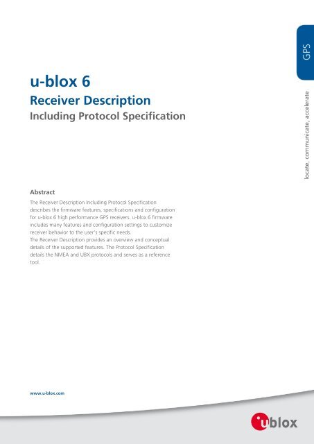
u-<strong>blox</strong> 6<br />
Receiver Description<br />
Including Protocol Specification<br />
Abstract<br />
The Receiver Description Including Protocol Specification<br />
describes the firmware features, specifications and configuration<br />
for u-<strong>blox</strong> 6 high performance GPS receivers. u-<strong>blox</strong> 6 firmware<br />
includes many features and configuration settings to customize<br />
receiver behavior to the user's specific needs.<br />
The Receiver Description provides an overview and conceptual<br />
details of the supported features. The Protocol Specification<br />
details the NMEA and UBX protocols and serves as a reference<br />
tool.<br />
www.u-<strong>blox</strong>.com
Document Information<br />
Title u-<strong>blox</strong> 6 Receiver Description<br />
Subtitle Including Protocol Specification<br />
Document type Manual<br />
Document number GPS.G6-SW-10018-A 46333, 1 Apr 2011<br />
Document status Revision for FW 7.03 (Public Release)<br />
This document and the use of any information contained therein, is subject to the acceptance of the u-<strong>blox</strong> terms and conditions. They can<br />
be downloaded from www.u-<strong>blox</strong>.com. u-<strong>blox</strong> makes no warranties based on the accuracy or completeness of the contents of this<br />
document and reserves the right to make changes to specifications and product descriptions at any time without notice. u-<strong>blox</strong> reserves all<br />
rights to this document and the information contained herein. Reproduction, use or disclosure to third parties without express permission<br />
is strictly prohibited. Copyright © 2011, u-<strong>blox</strong> AG.<br />
GPS.G6-SW-10018-A Public Release Page ii
Table of Contents<br />
Receiver Description .................................................................................................................................... 1<br />
1 Overview ............................................................................................................................................. 1<br />
2 Navigation Configuration Settings Description................................................................................ 1<br />
2.1 Platform settings .......................................................................................................................... 1<br />
2.2 Navigation Input Filters ............................................................................................................... 2<br />
2.3 Navigation Output Filters ............................................................................................................ 2<br />
2.4 Static Hold .................................................................................................................................... 3<br />
2.5 Freezing the Course Over Ground .............................................................................................. 3<br />
2.6 Degraded Navigation................................................................................................................... 3<br />
2.6.1 2D Navigation........................................................................................................................ 3<br />
2.6.2 Dead Reckoning, Extrapolating Positioning........................................................................ 3<br />
3 SBAS Configuration Settings Description ......................................................................................... 4<br />
3.1 SBAS (Satellite Based Augmentation Systems)........................................................................... 4<br />
3.2 SBAS Features ............................................................................................................................... 5<br />
3.3 SBAS Configuration...................................................................................................................... 6<br />
4 Serial Communication Ports Description........................................................................................... 7<br />
4.1 UART Ports.................................................................................................................................... 7<br />
4.2 USB Port ........................................................................................................................................ 8<br />
4.3 DDC Port ....................................................................................................................................... 8<br />
4.3.1 Read Access............................................................................................................................ 9<br />
4.3.1.1 Random Read Access ................................................................................................... 10<br />
4.3.1.2 Current Address Read .................................................................................................. 10<br />
4.3.2 Write Access......................................................................................................................... 11<br />
4.4 SPI Port........................................................................................................................................ 11<br />
4.4.1 Read Access.......................................................................................................................... 12<br />
4.4.2 Back-To-Back Read and Write Access................................................................................. 12<br />
4.5 How to change between protocols........................................................................................... 12<br />
5 Receiver Configuration..................................................................................................................... 14<br />
5.1 Configuration Concept .............................................................................................................. 14<br />
5.2 Organization of the Configuration Sections ............................................................................ 15<br />
5.3 Permanent Configuration Storage Media ................................................................................ 15<br />
5.4 Receiver Default Configuration ................................................................................................ 16<br />
6 NMEA Protocol Configuration.......................................................................................................... 16<br />
7 Forcing a Receiver Reset................................................................................................................... 16<br />
8 Remote Inventory ............................................................................................................................. 17<br />
8.1 Description.................................................................................................................................. 17<br />
8.2 Usage .......................................................................................................................................... 17<br />
9 Power Management ......................................................................................................................... 18<br />
9.1 Maximum Performance Mode................................................................................................... 18<br />
9.2 Eco Mode .................................................................................................................................... 18<br />
GPS.G6-SW-10018-A Public Release Page iii
9.3 Power Save Mode....................................................................................................................... 18<br />
9.3.1 Operation ............................................................................................................................ 18<br />
9.3.1.1 ON/OFF operation - long update period .................................................................... 19<br />
9.3.1.2 Cyclic tracking operation - short update period ........................................................ 20<br />
9.3.1.3 User controlled operation - update and search period of zero ................................ 20<br />
9.3.1.4 Satellite data download .............................................................................................. 20<br />
9.3.2 Configuration...................................................................................................................... 21<br />
9.3.2.1 Mode of operation ...................................................................................................... 21<br />
9.3.2.2 Update and search period ........................................................................................... 21<br />
9.3.2.3 Acquisition timeout ..................................................................................................... 22<br />
9.3.2.4 On time and wait for timefix ...................................................................................... 22<br />
9.3.2.5 Do not enter 'inactive for search' state when no fix ................................................. 22<br />
9.3.2.6 Update RTC and Eph.................................................................................................... 22<br />
9.3.2.7 EXTINT pin control ....................................................................................................... 22<br />
9.3.2.8 Grid offset .................................................................................................................... 22<br />
9.3.3 Communication, wake-up, FixNow interface, USB and AssistNow Autonomous ........... 23<br />
9.3.3.1 Communication............................................................................................................ 23<br />
9.3.3.2 Wake-up ....................................................................................................................... 23<br />
9.3.3.3 FixNow interface .......................................................................................................... 23<br />
9.3.3.4 behavior while USB host connected ........................................................................... 24<br />
9.3.3.5 Cooperation with the AssistNow Autonomous feature ............................................ 24<br />
9.3.4 Examples.............................................................................................................................. 24<br />
9.3.4.1 Use Grid Offset............................................................................................................. 24<br />
9.3.4.2 Use update periods of zero ......................................................................................... 25<br />
9.4 Peak current settings ................................................................................................................. 25<br />
9.5 Power On/Off command............................................................................................................ 25<br />
10 Time Mode Configuration .............................................................................................................. 25<br />
10.1 Introduction.............................................................................................................................. 25<br />
10.2 Fixed Position ........................................................................................................................... 25<br />
10.3 Survey-in ................................................................................................................................... 25<br />
11 Timepulse ....................................................................................................................................... 26<br />
11.1 Recommendations.................................................................................................................... 26<br />
11.2 Timepulse Configuration (u-<strong>blox</strong> 6) ........................................................................................ 27<br />
11.3 Configuring Timpulse with UBX-CFG-TP5............................................................................... 27<br />
11.3.1 Example 1: ......................................................................................................................... 28<br />
11.3.2 Example 2: ......................................................................................................................... 29<br />
11.4 Configuring Timpulse with UBX-CFG-TP ................................................................................ 30<br />
11.4.1 Example: ............................................................................................................................ 31<br />
12 Receiver Status Monitoring ........................................................................................................... 31<br />
12.1 Input/Output system ................................................................................................................ 32<br />
12.2 Jamming/Interference Indicator.............................................................................................. 32<br />
12.3 Jamming/Interference Monitor ............................................................................................... 32<br />
13 Aiding and Acquisition ................................................................................................................... 33<br />
13.1 Introduction.............................................................................................................................. 33<br />
GPS.G6-SW-10018-A Public Release Page iv
13.2 Startup Strategies..................................................................................................................... 33<br />
13.3 Aiding / Assisted GPS (A-GPS) .................................................................................................. 34<br />
13.4 Aiding Data .............................................................................................................................. 34<br />
13.5 Aiding Sequence ...................................................................................................................... 34<br />
13.6 AssistNow Online ..................................................................................................................... 34<br />
13.7 AssistNow Offline..................................................................................................................... 35<br />
13.7.1 Flash-based AlmanacPlus Overview ................................................................................. 36<br />
13.7.1.1 Download Procedure ................................................................................................. 36<br />
13.7.2 Host-based AlmanacPlus Overview .................................................................................. 37<br />
13.7.3 Message specifics............................................................................................................... 37<br />
13.7.3.1 Range checks .............................................................................................................. 37<br />
13.7.3.2 Changing ALP files ..................................................................................................... 38<br />
13.7.3.3 Sample Code............................................................................................................... 38<br />
13.8 AssistNow Autonomous........................................................................................................... 38<br />
13.8.1 Introduction....................................................................................................................... 38<br />
13.8.2 Concept.............................................................................................................................. 38<br />
13.8.3 Interface............................................................................................................................. 39<br />
13.8.4 Benefits and Drawbacks ................................................................................................... 40<br />
14 Precise Point Positioning ................................................................................................................ 41<br />
14.1 Introduction.............................................................................................................................. 41<br />
14.2 Configuration ........................................................................................................................... 41<br />
14.3 Monitoring ............................................................................................................................... 41<br />
15 Automotive Dead Reckoning (ADR) .............................................................................................. 41<br />
15.1 Introduction.............................................................................................................................. 42<br />
15.2 Timing ....................................................................................................................................... 42<br />
15.2.1 First Byte Reception .......................................................................................................... 43<br />
15.2.2 Time Mark on External Input ........................................................................................... 44<br />
15.2.3 Latency............................................................................................................................... 45<br />
15.3 Setup recommendations.......................................................................................................... 45<br />
15.3.1 GPS antenna placement, gyro placement and single tick origin ................................... 45<br />
15.3.2 Startup/Shutdown integration guideline ........................................................................ 46<br />
15.3.3 Navigation and measurement rate recommendations................................................... 46<br />
15.4 ESF Measurement Data (LEA-6R)............................................................................................. 46<br />
15.5 Gyro and Wheel Tick (GWT) Solution Configuration (LEA-6R) ............................................. 46<br />
15.5.1 Attached Gyroscope and Analog Wheel Ticks ................................................................ 46<br />
15.5.2 Using Serial Wheel Ticks ................................................................................................... 47<br />
NMEA Protocol ........................................................................................................................................... 49<br />
16 Protocol Overview .......................................................................................................................... 49<br />
17 Latitude and Longitude Format ..................................................................................................... 50<br />
18 Position Fix Flags in NMEA Mode .................................................................................................. 51<br />
19 NMEA Messages Overview ............................................................................................................ 52<br />
20 Standard Messages......................................................................................................................... 53<br />
20.1 DTM........................................................................................................................................... 53<br />
20.2 GBS ............................................................................................................................................ 54<br />
GPS.G6-SW-10018-A Public Release Page v
20.3 GGA........................................................................................................................................... 55<br />
20.4 GLL ............................................................................................................................................ 56<br />
20.5 GPQ ........................................................................................................................................... 57<br />
20.6 GRS ............................................................................................................................................ 58<br />
20.7 GSA............................................................................................................................................ 59<br />
20.8 GST ............................................................................................................................................ 60<br />
20.9 GSV............................................................................................................................................ 61<br />
20.10 RMC......................................................................................................................................... 62<br />
20.11 TXT .......................................................................................................................................... 63<br />
20.12 VTG.......................................................................................................................................... 64<br />
20.13 ZDA ......................................................................................................................................... 65<br />
21 Proprietary Messages ..................................................................................................................... 66<br />
21.1 UBX,00 ...................................................................................................................................... 66<br />
21.2 UBX,03 ...................................................................................................................................... 68<br />
21.3 UBX,04 ...................................................................................................................................... 70<br />
21.4 UBX,05 ...................................................................................................................................... 71<br />
21.5 UBX,06 ...................................................................................................................................... 73<br />
21.6 UBX ........................................................................................................................................... 75<br />
21.7 UBX,40 ...................................................................................................................................... 76<br />
21.8 UBX,41 ...................................................................................................................................... 77<br />
UBX Protocol............................................................................................................................................... 78<br />
22 UBX Protocol Key Features............................................................................................................. 78<br />
23 UBX Packet Structure...................................................................................................................... 78<br />
24 UBX Class IDs................................................................................................................................... 78<br />
25 UBX Payload Definition Rules ........................................................................................................ 79<br />
25.1 Structure Packing ..................................................................................................................... 79<br />
25.2 Message Naming ...................................................................................................................... 79<br />
25.3 Number Formats....................................................................................................................... 79<br />
26 UBX Checksum................................................................................................................................. 79<br />
27 UBX Message Flow.......................................................................................................................... 80<br />
27.1 Acknowledgement................................................................................................................... 80<br />
27.2 Polling Mechanism ................................................................................................................... 80<br />
28 UBX Messages Overview................................................................................................................ 81<br />
29 ACK (0x05) ....................................................................................................................................... 85<br />
29.1 ACK-ACK (0x05 0x01) ............................................................................................................... 85<br />
29.1.1 Message Acknowledged ................................................................................................... 85<br />
29.2 ACK-NAK (0x05 0x00)............................................................................................................... 85<br />
29.2.1 Message Not-Acknowledged............................................................................................ 85<br />
30 AID (0x0B)........................................................................................................................................ 86<br />
30.1 AID-ALM (0x0B 0x30) ............................................................................................................... 86<br />
30.1.1 Poll GPS Aiding Almanac Data ......................................................................................... 86<br />
30.1.2 Poll GPS Aiding Almanac Data for a SV ........................................................................... 86<br />
30.1.3 GPS Aiding Almanac Input/Output Message................................................................... 87<br />
30.2 AID-ALPSRV (0x0B 0x32) .......................................................................................................... 87<br />
GPS.G6-SW-10018-A Public Release Page vi
30.2.1 ALP client requests AlmanacPlus data from server ......................................................... 87<br />
30.2.2 ALP server sends AlmanacPlus data to client .................................................................. 88<br />
30.2.3 ALP client sends AlmanacPlus data to server. ................................................................. 89<br />
30.3 AID-ALP (0x0B 0x50)................................................................................................................. 89<br />
30.3.1 ALP file data transfer to the receiver............................................................................... 89<br />
30.3.2 Mark end of data transfer ................................................................................................ 90<br />
30.3.3 Acknowledges a data transfer ......................................................................................... 90<br />
30.3.4 Indicate problems with a data transfer ........................................................................... 90<br />
30.3.5 Poll the AlmanacPlus status.............................................................................................. 91<br />
30.4 AID-AOP (0x0B 0x33)................................................................................................................ 91<br />
30.4.1 Poll AssistNow Autonomous data .................................................................................... 91<br />
30.4.2 Poll AssistNow Autonomous data for one satellite ........................................................ 92<br />
30.4.3 AssistNow Autonomous data ........................................................................................... 92<br />
30.5 AID-DATA (0x0B 0x10) ............................................................................................................. 93<br />
30.5.1 Polls all GPS Initial Aiding Data........................................................................................ 93<br />
30.6 AID-EPH (0x0B 0x31) ................................................................................................................ 93<br />
30.6.1 Poll GPS Aiding Ephemeris Data ...................................................................................... 93<br />
30.6.2 Poll GPS Aiding Ephemeris Data for a SV ........................................................................ 93<br />
30.6.3 GPS Aiding Ephemeris Input/Output Message ................................................................ 94<br />
30.7 AID-HUI (0x0B 0x02)................................................................................................................. 95<br />
30.7.1 Poll GPS Health, UTC and ionosphere parameters.......................................................... 95<br />
30.7.2 GPS Health, UTC and ionosphere parameters ................................................................. 95<br />
30.8 AID-INI (0x0B 0x01) .................................................................................................................. 96<br />
30.8.1 Poll GPS Initial Aiding Data .............................................................................................. 96<br />
30.8.2 Aiding position, time, frequency, clock drift................................................................... 97<br />
30.9 AID-REQ (0x0B 0x00) ................................................................................................................ 98<br />
30.9.1 Sends a poll (AID-DATA) for all GPS Aiding Data ........................................................... 98<br />
31 CFG (0x06)........................................................................................................................................ 99<br />
31.1 CFG-ANT (0x06 0x13)................................................................................................................ 99<br />
31.1.1 Poll Antenna Control Settings.......................................................................................... 99<br />
31.1.2 Get/Set Antenna Control Settings.................................................................................... 99<br />
31.2 CFG-CFG (0x06 0x09) .............................................................................................................. 100<br />
31.2.1 Clear, Save and Load configurations ............................................................................ 100<br />
31.3 CFG-DAT (0x06 0x06).............................................................................................................. 102<br />
31.3.1 Poll Datum Setting.......................................................................................................... 102<br />
31.3.2 Set Standard Datum........................................................................................................ 102<br />
31.3.3 Set User-defined Datum ................................................................................................. 102<br />
31.3.4 Get currently selected Datum......................................................................................... 103<br />
31.4 CFG-EKF (0x06 0x12)............................................................................................................... 104<br />
31.4.1 Poll EKF Module Settings................................................................................................ 104<br />
31.4.2 Get/Set EKF Module Settings.......................................................................................... 104<br />
31.5 CFG-ESFGWT (0x06 0x29) ....................................................................................................... 106<br />
31.5.1 Get/Set settings of gyro+wheel tick sol (GWT) - LEA-6R............................................... 106<br />
31.6 CFG-FXN (0x06 0x0E) .............................................................................................................. 107<br />
GPS.G6-SW-10018-A Public Release Page vii
31.6.1 Poll FXN configuration.................................................................................................... 107<br />
31.6.2 RXM FixNOW configuration. ......................................................................................... 107<br />
31.7 CFG-INF (0x06 0x02) ............................................................................................................... 108<br />
31.7.1 Poll INF message configuration for one protocol ......................................................... 108<br />
31.7.2 Information message configuration .............................................................................. 109<br />
31.8 CFG-ITFM (0x06 0x39)............................................................................................................. 110<br />
31.8.1 Jamming/Interference Monitor configuration. ............................................................. 110<br />
31.9 CFG-MSG (0x06 0x01) ............................................................................................................. 111<br />
31.9.1 Poll a message configuration ......................................................................................... 111<br />
31.9.2 Set Message Rate(s)......................................................................................................... 111<br />
31.9.3 Set Message Rate ............................................................................................................ 112<br />
31.10 CFG-NAV5 (0x06 0x24) ......................................................................................................... 112<br />
31.10.1 Poll Navigation Engine Settings ................................................................................... 112<br />
31.10.2 Get/Set Navigation Engine Settings ............................................................................. 113<br />
31.11 CFG-NAVX5 (0x06 0x23)....................................................................................................... 114<br />
31.11.1 Poll Navigation Engine Expert Settings ....................................................................... 114<br />
31.11.2 Get/Set Navigation Engine Expert Settings ................................................................. 114<br />
31.12 CFG-NMEA (0x06 0x17) ........................................................................................................ 116<br />
31.12.1 Poll the NMEA protocol configuration ........................................................................ 116<br />
31.12.2 Set/Get the NMEA protocol configuration .................................................................. 116<br />
31.13 CFG-NVS (0x06 0x22) ............................................................................................................ 117<br />
31.13.1 Clear, Save and Load non-volatile storage data ......................................................... 117<br />
31.14 CFG-PM2 (0x06 0x3B) ........................................................................................................... 119<br />
31.14.1 Poll extended Power Management configuration ..................................................... 119<br />
31.14.2 Extended Power Management configuration............................................................. 119<br />
31.15 CFG-PM (0x06 0x32) ............................................................................................................. 121<br />
31.15.1 Poll Power Management configuration ...................................................................... 121<br />
31.15.2 Power Management configuration ............................................................................. 121<br />
31.16 CFG-PRT (0x06 0x00)............................................................................................................. 123<br />
31.16.1 Polls the configuration of the used I/O Port................................................................ 123<br />
31.16.2 Polls the configuration for one I/O Port ...................................................................... 123<br />
31.16.3 Get/Set Port Configuration for UART .......................................................................... 123<br />
31.16.4 Get/Set Port Configuration for USB Port ..................................................................... 126<br />
31.16.5 Get/Set Port Configuration for SPI Port ....................................................................... 127<br />
31.16.6 Get/Set Port Configuration for DDC Port .................................................................... 130<br />
31.17 CFG-RATE (0x06 0x08) .......................................................................................................... 132<br />
31.17.1 Poll Navigation/Measurement Rate Settings............................................................... 132<br />
31.17.2 Navigation/Measurement Rate Settings ...................................................................... 132<br />
31.18 CFG-RINV (0x06 0x34)........................................................................................................... 133<br />
31.18.1 Poll contents of Remote Inventory .............................................................................. 133<br />
31.18.2 Set/Get contents of Remote Inventory ........................................................................ 133<br />
31.19 CFG-RST (0x06 0x04)............................................................................................................. 134<br />
31.19.1 Reset Receiver / Clear Backup Data Structures ............................................................ 134<br />
31.20 CFG-RXM (0x06 0x11)........................................................................................................... 135<br />
GPS.G6-SW-10018-A Public Release Page viii
31.20.1 Poll RXM configuration ................................................................................................ 135<br />
31.20.2 RXM configuration........................................................................................................ 135<br />
31.21 CFG-SBAS (0x06 0x16) .......................................................................................................... 136<br />
31.21.1 Poll contents of SBAS Configuration ........................................................................... 136<br />
31.21.2 SBAS Configuration....................................................................................................... 136<br />
31.22 CFG-TMODE2 (0x06 0x3D) ................................................................................................... 138<br />
31.22.1 Poll Time Mode Settings............................................................................................... 138<br />
31.22.2 Time Mode Settings 2 ................................................................................................... 138<br />
31.23 CFG-TMODE (0x06 0x1D) ..................................................................................................... 139<br />
31.23.1 Poll Time Mode Settings............................................................................................... 139<br />
31.23.2 Time Mode Settings ...................................................................................................... 139<br />
31.24 CFG-TP5 (0x06 0x31)............................................................................................................. 140<br />
31.24.1 Poll Timepulse Parameters............................................................................................ 140<br />
31.24.2 Poll TimePulse Parameters............................................................................................ 140<br />
31.24.3 Get/Set TimePulse Parameters...................................................................................... 141<br />
31.25 CFG-TP (0x06 0x07)............................................................................................................... 142<br />
31.25.1 Poll TimePulse Parameters............................................................................................ 142<br />
31.25.2 Get/Set TimePulse Parameters...................................................................................... 142<br />
31.26 CFG-USB (0x06 0x1B) ............................................................................................................ 143<br />
31.26.1 Poll a USB configuration............................................................................................... 143<br />
31.26.2 Get/Set USB Configuration ........................................................................................... 143<br />
32 ESF (0x10) ...................................................................................................................................... 145<br />
32.1 ESF-MEAS (0x10 0x02) ............................................................................................................ 145<br />
32.1.1 External Sensor Fusion Measurements (LEA-6R) ........................................................... 145<br />
32.2 ESF-STATUS (0x10 0x10) ......................................................................................................... 146<br />
32.2.1 Sensor Fusion Status Information (LEA-6R) ................................................................... 146<br />
33 INF (0x04)....................................................................................................................................... 148<br />
33.1 INF-DEBUG (0x04 0x04) .......................................................................................................... 148<br />
33.1.1 ASCII String output, indicating debug output .............................................................. 148<br />
33.2 INF-ERROR (0x04 0x00)........................................................................................................... 148<br />
33.2.1 ASCII String output, indicating an error ........................................................................ 148<br />
33.3 INF-NOTICE (0x04 0x02) ......................................................................................................... 149<br />
33.3.1 ASCII String output, with informational contents ........................................................ 149<br />
33.4 INF-TEST (0x04 0x03) .............................................................................................................. 149<br />
33.4.1 ASCII String output, indicating test output................................................................... 149<br />
33.5 INF-WARNING (0x04 0x01)..................................................................................................... 150<br />
33.5.1 ASCII String output, indicating a warning..................................................................... 150<br />
34 MON (0x0A)................................................................................................................................... 151<br />
34.1 MON-HW2 (0x0A 0x0B).......................................................................................................... 151<br />
34.1.1 Extended Hardware Status ............................................................................................. 151<br />
34.2 MON-HW (0x0A 0x09)............................................................................................................ 152<br />
34.2.1 Hardware Status.............................................................................................................. 152<br />
34.2.2 Hardware Status.............................................................................................................. 153<br />
34.3 MON-IO (0x0A 0x02) .............................................................................................................. 154<br />
GPS.G6-SW-10018-A Public Release Page ix
34.3.1 I/O Subsystem Status ....................................................................................................... 154<br />
34.4 MON-MSGPP (0x0A 0x06) ...................................................................................................... 155<br />
34.4.1 Message Parse and Process Status.................................................................................. 155<br />
34.5 MON-RXBUF (0x0A 0x07)....................................................................................................... 155<br />
34.5.1 Receiver Buffer Status..................................................................................................... 155<br />
34.6 MON-RXR (0x0A 0x21) ........................................................................................................... 156<br />
34.6.1 Receiver Status Information ........................................................................................... 156<br />
34.7 MON-TXBUF (0x0A 0x08) ....................................................................................................... 156<br />
34.7.1 Transmitter Buffer Status ............................................................................................... 156<br />
34.8 MON-VER (0x0A 0x04) ........................................................................................................... 157<br />
34.8.1 Receiver/Software/ROM Version .................................................................................... 157<br />
35 NAV (0x01)..................................................................................................................................... 158<br />
35.1 NAV-AOPSTATUS (0x01 0x60)................................................................................................ 158<br />
35.1.1 AssistNow Autonomous Status....................................................................................... 158<br />
35.2 NAV-CLOCK (0x01 0x22) ........................................................................................................ 158<br />
35.2.1 Clock Solution ................................................................................................................. 158<br />
35.3 NAV-DGPS (0x01 0x31)........................................................................................................... 159<br />
35.3.1 DGPS Data Used for NAV................................................................................................ 159<br />
35.4 NAV-DOP (0x01 0x04) ............................................................................................................ 160<br />
35.4.1 Dilution of precision ....................................................................................................... 160<br />
35.5 NAV-EKFSTATUS (0x01 0x40)................................................................................................. 160<br />
35.5.1 Dead Reckoning Software Status................................................................................... 160<br />
35.6 NAV-POSECEF (0x01 0x01) ..................................................................................................... 162<br />
35.6.1 Position Solution in ECEF ................................................................................................ 162<br />
35.7 NAV-POSLLH (0x01 0x02) ....................................................................................................... 163<br />
35.7.1 Geodetic Position Solution ............................................................................................. 163<br />
35.8 NAV-SBAS (0x01 0x32) ........................................................................................................... 163<br />
35.8.1 SBAS Status Data............................................................................................................. 163<br />
35.9 NAV-SOL (0x01 0x06) ............................................................................................................. 165<br />
35.9.1 Navigation Solution Information ................................................................................... 165<br />
35.10 NAV-STATUS (0x01 0x03) ..................................................................................................... 166<br />
35.10.1 Receiver Navigation Status ........................................................................................... 166<br />
35.11 NAV-SVINFO (0x01 0x30) ..................................................................................................... 168<br />
35.11.1 Space Vehicle Information............................................................................................ 168<br />
35.12 NAV-TIMEGPS (0x01 0x20) ................................................................................................... 170<br />
35.12.1 GPS Time Solution......................................................................................................... 170<br />
35.13 NAV-TIMEUTC (0x01 0x21)................................................................................................... 170<br />
35.13.1 UTC Time Solution......................................................................................................... 170<br />
35.14 NAV-VELECEF (0x01 0x11).................................................................................................... 171<br />
35.14.1 Velocity Solution in ECEF .............................................................................................. 171<br />
35.15 NAV-VELNED (0x01 0x12) .................................................................................................... 172<br />
35.15.1 Velocity Solution in NED............................................................................................... 172<br />
36 RXM (0x02) .................................................................................................................................... 173<br />
36.1 RXM-ALM (0x02 0x30)............................................................................................................ 173<br />
GPS.G6-SW-10018-A Public Release Page x
36.1.1 Poll GPS Constellation Almanach Data .......................................................................... 173<br />
36.1.2 Poll GPS Constellation Almanach Data for a SV............................................................ 173<br />
36.1.3 GPS Aiding Almanach Input/Output Message............................................................... 174<br />
36.2 RXM-EPH (0x02 0x31)............................................................................................................. 174<br />
36.2.1 Poll GPS Constellation Ephemeris Data ......................................................................... 174<br />
36.2.2 Poll GPS Constellation Ephemeris Data for a SV ........................................................... 175<br />
36.2.3 GPS Aiding Ephemeris Input/Output Message .............................................................. 175<br />
36.3 RXM-PMREQ (0x02 0x41) ....................................................................................................... 176<br />
36.3.1 Requests a Power Management task............................................................................. 176<br />
36.4 RXM-RAW (0x02 0x10) ........................................................................................................... 176<br />
36.4.1 Raw Measurement Data ................................................................................................. 176<br />
36.5 RXM-SFRB (0x02 0x11) ........................................................................................................... 177<br />
36.5.1 Subframe Buffer.............................................................................................................. 177<br />
36.6 RXM-SVSI (0x02 0x20) ............................................................................................................ 178<br />
36.6.1 SV Status Info .................................................................................................................. 178<br />
37 TIM (0x0D) ..................................................................................................................................... 180<br />
37.1 TIM-SVIN (0x0D 0x04)............................................................................................................. 180<br />
37.1.1 Survey-in data.................................................................................................................. 180<br />
37.2 TIM-TM2 (0x0D 0x03) ............................................................................................................. 180<br />
37.2.1 Time mark data ............................................................................................................... 180<br />
37.3 TIM-TP (0x0D 0x01) ................................................................................................................ 182<br />
37.3.1 Timepulse Timedata........................................................................................................ 182<br />
37.4 TIM-VRFY (0x0D 0x06)............................................................................................................ 183<br />
37.4.1 Sourced Time Verification .............................................................................................. 183<br />
RTCM Protocol .......................................................................................................................................... 184<br />
38 Introduction................................................................................................................................... 184<br />
39 Supported Messages..................................................................................................................... 184<br />
40 Configuration ................................................................................................................................ 184<br />
41 Output ........................................................................................................................................... 184<br />
42 Restrictions .................................................................................................................................... 184<br />
43 Reference....................................................................................................................................... 185<br />
Appendix .................................................................................................................................................. 186<br />
A u-<strong>blox</strong> 6 Default Settings............................................................................................................... 186<br />
A.1 Antenna Supervisor Settings (UBX-CFG-ANT)........................................................................ 186<br />
A.2 Datum Settings (UBX-CFG-DAT) ............................................................................................. 186<br />
A.3 Navigation Settings (UBX-CFG-NAV5) .................................................................................... 186<br />
A.4 Navigation Settings (UBX-CFG-NAVX5).................................................................................. 187<br />
A.5 Output Rates (UBX-CFG-RATE) ............................................................................................... 187<br />
A.6 Fix Now Configuration (UBX-CFG-FXN).................................................................................. 187<br />
A.7 Power Management Configuration (UBX-CFG-PM) .............................................................. 188<br />
A.8 Power Management 2 Configuration (UBX-CFG-PM2) ......................................................... 188<br />
A.9 Receiver Manager Configuration (UBX-CFG-RXM)................................................................ 189<br />
A.10 SBAS Configuration (UBX-CFG-SBAS) ................................................................................... 189<br />
A.11 Port Setting (UBX-CFG-PRT) .................................................................................................. 189<br />
GPS.G6-SW-10018-A Public Release Page xi
A.12 Port Setting (UBX-CFG-USB).................................................................................................. 190<br />
A.13 Message Settings (UBX-CFG-MSG)........................................................................................ 190<br />
A.14 NMEA Protocol Settings (UBX-CFG-NMEA).......................................................................... 190<br />
A.15 INF Messages Settings (UBX-CFG-INF) .................................................................................. 190<br />
A.16 Timepulse Settings (UBX-CFG-TP) ......................................................................................... 191<br />
A.17 Timepulse Settings (UBX-CFG-TP5) ...................................................................................... 191<br />
A.18 Jammer/Interference Monitor (UBX-CFG-ITFM)................................................................... 192<br />
A.19 Remote inventory (UBX-CFG-RINV) ...................................................................................... 192<br />
B u-<strong>blox</strong> 6 Standard firmware versions............................................................................................ 192<br />
C Geodetic Datum .............................................................................................................................. 193<br />
C.1 Predefined Datum.................................................................................................................... 193<br />
C.2 Ellipsoids ................................................................................................................................... 199<br />
C.3 Rotation and Scale ................................................................................................................... 199<br />
Related Documents ................................................................................................................................. 200<br />
Overview .............................................................................................................................................. 200<br />
Related Documents for Modules ........................................................................................................ 200<br />
u-<strong>blox</strong> 6 ............................................................................................................................................. 200<br />
Contact...................................................................................................................................................... 201<br />
Headquarters........................................................................................................................................ 201<br />
Offices................................................................................................................................................... 201<br />
GPS.G6-SW-10018-A Public Release Page xii
Receiver Description<br />
1 Overview<br />
The Receiver Description including Protocol Specification is an important resource for integrating and<br />
configuring your u-<strong>blox</strong> 6 GPS receiver. This document has a modular structure and it is not necessary to read it<br />
from the beginning to the end. There are 2 main sections: The Receiver Description and the Protocol<br />
Specification.<br />
The Receiver Description describes the software aspects of system features and configuration of u-<strong>blox</strong> 6 GPS<br />
technology. The Receiver Description is structured according to functionalities, with links provided to the<br />
corresponding NMEA and UBX messages, which are described in the Protocol Specification.<br />
The Protocol Specification is a reference describing the software messages used by your u-<strong>blox</strong> receiver and is<br />
organized by the specific NMEA and UBX messages.<br />
2 Navigation Configuration Settings Description<br />
This section relates to the configuration message CFG-NAV5.<br />
2.1 Platform settings<br />
u-<strong>blox</strong> positioning technology supports different dynamic platform models to adjust the navigation engine to<br />
the expected application environment. These platform settings can be changed dynamically without performing<br />
a power cycle or reset. The settings improve the receiver's interpretation of the measurements and thus provide<br />
a more accurate position output. Setting the receiver to an unsuitable platform model for the given application<br />
environment results in a loss of receiver performance and position accuracy.<br />
Dynamic Platform Model<br />
Platform<br />
Portable<br />
Stationary<br />
Pedestrian<br />
Automotive<br />
At sea<br />
Airborne
Dynamic Platform Model continued<br />
Platform<br />
Airborne
message must be checked.<br />
2.4 Static Hold<br />
Static Hold mode allows the navigation algorithms to decrease the noise in the position output when the<br />
velocity is below a pre-defined ‘Static Hold Threshold’. This reduces the position wander caused by<br />
environmental factors such as multi-path and improves position accuracy especially in stationary applications.<br />
By default, static hold mode is disabled.<br />
Static Hold mode may not be used on GPS receivers with Automotive Dead Reckoning (ADR)<br />
enabled.<br />
If the speed drops below the defined ‘Static Hold Threshold’, the static hold mode will be activated. Once Static<br />
Hold mode has been entered, the position output is kept static and the velocity is set to zero until there is<br />
evidence of movement again. Such evidence can be velocity, acceleration, changes of the valid flag (e.g.<br />
position accuracy estimate exceeding the Position Accuracy Mask, see also section Navigation Output Filters),<br />
position displacement, etc.<br />
2.5 Freezing the Course Over Ground<br />
The receiver derives the course over ground from the GNSS velocity information. If the velocity cannot be<br />
calculated with sufficient accuracy (e.g., with bad signals) or if the absolute speed value is very low (under 0.<br />
1m/s) then the course over ground value becomes inaccurate too. In this case the course over ground value is<br />
frozen, i.e. the previous value is kept and its accuracy is degraded over time. These frozen values will not be<br />
output in the NMEA messages NMEA-RMC and NMEA-VTG unless the NMEA protocol is explicitely configured<br />
to do so (see NMEA Protocol Configuration).<br />
The course over ground will never be frozen on GPS receivers with Automotive Dead Reckoning<br />
(ADR) enabled.<br />
2.6 Degraded Navigation<br />
Degraded navigation describes all navigation modes which use less than 4 Satellite Vehicles (SVs).<br />
2.6.1 2D Navigation<br />
If the receiver only has 3 SVs for calculating a position, the navigation algorithm uses a constant altitude to<br />
compensate for the missing fourth SV. When an SV is lost after a successful 3D fix (min. 4 SVs available), the<br />
altitude is kept constant at the last known value. This is called a 2D fix.<br />
u-<strong>blox</strong> positioning technology does not calculate any solution with less than 3 SVs. Only u-<strong>blox</strong><br />
timing receivers can, when stationary, calculate a timing solution with only 1 SV.<br />
2.6.2 Dead Reckoning, Extrapolating Positioning<br />
This linear extrapolation feature is enabled by setting the drLimit parameter in CFG-NAV5. The extrapolation<br />
algorithm becomes active as soon as the receiver no longer achieves a position fix with a sufficient position<br />
accuracy or DOP value (see section Navigation Output Filters). It keeps a fixed track (heading is equal to the last<br />
calculated heading) until the dead reckoning limit is reached, or a position fix is again possible. The position is<br />
extrapolated, and the fix type is indicated as 1 (DR only). See NMEA V2.1 for NMEA fix flags.<br />
For automotive dead reckoning (ADR), u-<strong>blox</strong> offers a solution based on input from external sensors as<br />
described in section Description of Automotive Dead Reckoning (ADR). The mentioned ADR solution is<br />
unrelated to this linear extrapolation feature. The ADR solution allows high accuracy position solutions for<br />
automotive applications in situations with poor or no GPS coverage. This technology relies on additional inputs<br />
such as a turn rate sensor (gyro) or a speed sensor (odometer or wheel tick).<br />
GPS.G6-SW-10018-A Public Release Page 3 of 201
Do not use the linear extrapolation feature together with a u-<strong>blox</strong> ADR sensor-based Dead<br />
Reckoning GPS solution, as it will dilute the result!<br />
3 SBAS Configuration Settings Description<br />
3.1 SBAS (Satellite Based Augmentation Systems)<br />
SBAS (Satellite Based Augmentation System) is an augmentation technology for GPS, which calculates GPS<br />
integrity and correction data with RIMS (Ranging and Integrity Monitoring Stations) on the ground and uses<br />
geostationary satellites (GEOs) to broadcast GPS integrity and correction data to GPS users. The correction data<br />
is transmitted on the GPS L1 frequency (1575.42 MHz), and therefore no additional receiver is required to<br />
make use of the correction and integrity data.<br />
SBAS Principle<br />
There are several compatible SBAS systems available or in development all around the world:<br />
• WAAS (Wide Area Augmentation System) for North America has been in operation since 2003.<br />
• MSAS (Multi-Functional Satellite Augmentation System) for Asia has been in operation since 2007.<br />
• EGNOS (European Geostationary Navigation Overlay Service) is at the time of writing in test mode.<br />
• GAGAN (GPS Aided Geo Augmented Navigation), developed by the Indian government is at the time of<br />
writing in test mode.<br />
SBAS support allows u-<strong>blox</strong> GPS technology to take full advantage of the augmentation systems that are<br />
currently available (WAAS, EGNOS, MSAS), as well as those being tested and planned (such as GAGAN).<br />
With SBAS enabled the user benefits from additional satellites for ranging (navigation). u-<strong>blox</strong> GPS technology<br />
uses the available SBAS Satellites for navigation just like GPS satellites, if the SBAS satellites offer this service.<br />
To improve position accuracy SBAS uses different types of correction data:<br />
• Fast Corrections for short-term disturbances in GPS signals (due to clock problems, etc).<br />
• Long-term corrections for GPS clock problems, broadcast orbit errors etc.<br />
GPS.G6-SW-10018-A Public Release Page 4 of 201
• Ionosphere corrections for Ionosphere activity<br />
Another benefit of SBAS is the use of GPS integrity information. In this way SBAS Control stations can ‘disable’<br />
the use of GPS satellites within a 6 second alarm time in case of major GPS satellite problems. If integrity<br />
monitoring is enabled, u-<strong>blox</strong> GPS technology only uses satellites, for which integrity information is available.<br />
For more information on SBAS and associated services please refer to<br />
• RTCA/DO-229D (MOPS). Available from www.rtca.org<br />
• gps.faa.gov for information on WAAS.<br />
• www.esa.int for information on EGNOS.<br />
• www.essp-sas.eu for information about European Satellite Services Provider (ESSP), the EGNOS operations<br />
manager.<br />
GEO satellites used by WAAS, EGNOS and MSAS (as of November 2010)<br />
GEO Identification Position GPS PRN SBAS Provider<br />
AMR 98° W 133 WAAS<br />
Inmarsat 3F3, POR 178° E 134 WAAS<br />
TeleSat Anik F1R 107.3° W 138 WAAS<br />
Inmarsat 3F2 AOR-E 15.5° W 120 EGNOS<br />
Artemis 21.5° W 124 EGNOS<br />
Inmarsat 3F5 IOR-W 25° E 126 EGNOS<br />
MTSAT-1R 140° E 129 MSAS<br />
MTSAT-2 145° E 137 MSAS<br />
3.2 SBAS Features<br />
This u-<strong>blox</strong> SBAS implementation is, in accordance with standard RTCA/DO-229D, a class Beta-1<br />
equipment. All timeouts etc. are chosen for the En Route Case. Do not use this equipment under<br />
any circumstances for safety of life applications!<br />
u-<strong>blox</strong> receivers are capable of receiving multiple SBAS satellites in parallel, even from different SBAS systems<br />
(WAAS, EGNOS, MSAS, etc.). They can be tracked and used for navigation simultaneously. At least three SBAS<br />
satellites can be tracked in parallel. Every SBAS satellite tracked utilizes one vacant GPS receiver tracking<br />
channel. Only the number of receiver channels limits the total number of satellites used. Each SBAS satellite,<br />
which broadcasts ephemeris or almanac information, can be used for navigation, just like a normal GPS<br />
satellite.<br />
For receiving correction data, the u-<strong>blox</strong> GPS receiver automatically chooses the best SBAS satellite as its<br />
primary source. It will select only one since the information received from other SBAS GEOs is redundant and/or<br />
could be inconsistent. The selection strategy is determined by the proximity of the GEOs, the services offered by<br />
the GEO, the configuration of the receiver (Testmode allowed/disallowed, Integrity enabled/disabled) and the<br />
signal link quality to the GEO.<br />
In case corrections are available from the chosen GEO and used in the navigation calculation, the DGPS flag is<br />
set in the receiver’s output protocol messages (see NAV-SOL, NAV-STATUS, NAV-SVINFO, NMEA Position<br />
Fix Flags description). The message NAV-SBAS provides detailed information about which corrections<br />
are available and applied.<br />
The most important SBAS feature for accuracy improvement is Ionosphere correction. The measured data from<br />
RIMS stations of a region are combined to a TEC (Total Electron Content) Map. This map is transferred to the<br />
GPS devices via the GEOs to allow a correction of the ionosphere error on each received satellite.<br />
GPS.G6-SW-10018-A Public Release Page 5 of 201
Supported SBAS messages<br />
Message Type Message Content Used from GEO<br />
0(0/2) Test Mode All<br />
1 PRN Mask Assignment Primary<br />
2, 3, 4, 5 Fast Corrections Primary<br />
6 Integrity Primary<br />
7 Fast Correction Degradation Primary<br />
9 GEO Navigation (Ephemeris) All<br />
10 Degradation Primary<br />
12 Time Offset Primary<br />
17 GEO Almanacs All<br />
18 Ionosphere Grid Point Assignment Primary<br />
24 Mixed Fast / Long term Corrections Primary<br />
25 Long term Corrections Primary<br />
26 Ionosphere Delays Primary<br />
As each GEO services a specific region, the correction signal is only useful within that region. Therefore, mission<br />
planning is crucial to determine the best possible configuration. The different stages (Testmode vs. Operational)<br />
of the various SBAS systems further complicate this task. The following examples show possible scenarios:<br />
Example 1: SBAS Receiver in North America<br />
At the time of writing, the WAAS system is in operational stage, whereas the EGNOS system is still in test<br />
mode. Therefore, and especially in the eastern parts of the US, care must be taken in order not to have EGNOS<br />
satellites taking preference over WAAS satellites. This can be achieved by disallowing Test Mode use (this<br />
inhibits EGNOS satellites from being used as a correction data source), but keeping the PRN Mask to have all<br />
SBAS GEOs enabled (which allows EGNOS GEOs to be used for navigation).<br />
Example 2: SBAS Receiver in Europe<br />
At the time of writing, the EGNOS system is still in test mode. To try out EGNOS operation, Testmode usage<br />
must be enabled. Since some WAAS satellites can be received in the western parts of Europe but don't carry<br />
correction data for the European continent, the GEOs from all but the EGNOS system should be disallowed,<br />
using the PRN Mask. It is important to understand that while EGNOS is in test mode, anything can happen to<br />
the EGNOS signals, such as sudden interruption of service or broadcast of invalid or inconsistent data.<br />
Although u-<strong>blox</strong> GPS receivers try to select the best available SBAS correction data, it is<br />
recommended to disallow the usage of unwanted SBAS satellites by configuration.<br />
3.3 SBAS Configuration<br />
To configure the SBAS functionalities use the UBX proprietary message UBX–CFG–SBAS (SBAS<br />
Configuration).<br />
SBAS Configuration parameters<br />
Parameter<br />
Description<br />
Mode - SBAS Subsystem<br />
Enables or disables the SBAS subsystem<br />
Mode - Allow test mode usage Allow / Disallow SBAS usage from satellites in Test Mode (Message 0)<br />
Services/Usage - Ranging<br />
Use the SBAS satellites for navigation<br />
Services/Usage - Apply SBAS<br />
correction data<br />
Services/Usage - Apply integrity<br />
information<br />
Combined enable/disable switch for Fast-, Long-Term and Ionosphere<br />
Corrections<br />
Use integrity data<br />
GPS.G6-SW-10018-A Public Release Page 6 of 201
SBAS Configuration parameters continued<br />
Parameter<br />
Number of tracking channels<br />
PRN Mask<br />
Description<br />
Sets how many channels are reserved for SBAS tracking (e.g., if this is<br />
set to three and five SBAS SVs are acquired, only three of these will<br />
prioritized over available GPS signals.<br />
Allows selectively enabling/disabling SBAS satellites (e.g. restrict SBAS<br />
usage to WAAS-only).<br />
By default SBAS is enabled with three prioritized SBAS channels and it will use any received SBAS satellites<br />
(except for those in test mode) for navigation, ionosphere parameters and corrections.<br />
4 Serial Communication Ports Description<br />
u-<strong>blox</strong> positioning technology comes with a highly flexible communication interface. It supports the NMEA and<br />
the proprietary UBX protocols, and is truly multi-port and multi-protocol capable. Each protocol (UBX, NMEA)<br />
can be assigned to several ports at the same time (multi-port capability) with individual settings (e.g. baud rate,<br />
message rates, etc.) for each port. It is even possible to assign more than one protocol (e.g. UBX protocol and<br />
NMEA at the same time) to a single port (multi-protocol capability), which is particularly useful for debugging<br />
purposes.<br />
To enable a message on a port the UBX and/or NMEA protocol must be enabled on that port using the UBX<br />
proprietary message CFG-PRT. This message also allows changing port-specific settings (baud rate, address etc.<br />
). See CFG-MSG for a description of the mechanism for enabling and disabling messages.<br />
A target in the context of the I/O system is an I/O port. The following table shows the target numbers used<br />
Target Number assignment<br />
Target #<br />
0 DDC (I2C compatible)<br />
1 UART 1<br />
2 UART 2<br />
3 USB<br />
4 SPI<br />
5 reserved<br />
Electrical Interface<br />
4.1 UART Ports<br />
One or two Universal Asynchronous Receiver/Transmitter (UART) ports are featured, that can be used to<br />
transmit GPS measurements, monitor status information and configure the receiver. See our online product<br />
selector matrix for availability.<br />
The serial ports consist of an RX and a TX line. Neither handshaking signals nor hardware flow control signals<br />
are available. These serial ports operate in asynchronous mode. The baud rates can be configured individually<br />
for each serial port. However, there is no support for setting different baud rates for reception and transmission<br />
or for different protocols on the same port.<br />
Possible UART Interface Configurations<br />
Baud Rate Data Bits Parity Stop Bits<br />
4800 8 none 1<br />
9600 8 none 1<br />
19200 8 none 1<br />
38400 8 none 1<br />
57600 8 none 1<br />
GPS.G6-SW-10018-A Public Release Page 7 of 201
Possible UART Interface Configurations continued<br />
Baud Rate Data Bits Parity Stop Bits<br />
115200 8 none 1<br />
If the amount of data configured is too much for a certain port's bandwidth (e.g. all UBX messages<br />
output on a UART port with a baud rate of 9600), the buffer will fill up. Once the buffer space is<br />
exceeded, new messages to be sent will be dropped.<br />
To ensure data validity on all communication interfaces (SPI, DDC, USB, UART) Firmware 6.02<br />
implements a maximum lifetime for transmit packets of 2 seconds. After a message is generated, if<br />
transmission does not begin within this time limit, the message will be discarded.<br />
If the number of bytes to be transmitted and the baud rate are selected so that transmission cannot be fully<br />
completed within the timeout period, then the host will not receive some messages. To prevent message losses<br />
due to timeout, the baudrate and communication speed or the number of enabled messages should be<br />
selected so that the expected number of bytes can be transmitted in less than one second.<br />
Firmware 7.01 and later do not implement a timeout for messages, but will drop new messages if<br />
the internal buffer is full.<br />
If the host does not communicate over SPI or DDC for more than approximately 2 seconds, the device assumes<br />
that the host is no longer using this interface and no more packets are scheduled for this port. This mechanism<br />
can be changed enabling "extended TX timeouts", in which case the receiver delays idling the port until the<br />
allocated and undelivered bytes for this port reach 4 kB. This feature is especially useful when using the<br />
TX-ready feature with a message output rate of less than once per second, and polling data only when data is<br />
available, determined by the TX-ready pin becoming active.<br />
Note that for protocols such as NMEA or UBX, it does not make sense to change the default word length<br />
values (data bits) since these properties are defined by the protocol and not by the electrical interface.<br />
See CFG-PRT for UART for a description of the contents of the UART port configuration message.<br />
4.2 USB Port<br />
One Universal Serial Bus (USB) port is featured. See our online product selector matrix for availability. This port<br />
can be used for communication purposes and to power the GPS receiver.<br />
The USB interface supports two different power modes:<br />
• In Self Powered Mode the receiver is powered by its own power supply. VDDUSB is used to detect the<br />
availability of the USB port, i.e. whether the receiver is connected to a USB host.<br />
• In Bus Powered Mode the device is powered by the USB bus, therefore no additional power supply is<br />
needed. In this mode the default maximum current that can be drawn by the receiver is 100 mA for u-<strong>blox</strong> 6<br />
(120 mA for u-<strong>blox</strong> 5). See CFG-USB for a description on how to change this maximum. Configuring Bus<br />
Powered Mode indicates that the device will enter a low power state with disabled GPS functionality when<br />
the host suspends the device, e.g. when the host is put into stand-by mode.<br />
The voltage range for VDDUSB is specified from 3.0V to 3.6V, which differs slightly from the<br />
specification for VCC<br />
4.3 DDC Port<br />
A Display Data Channel (DDC) bus is implemented, which is a 2-wire communication interface compatible with<br />
the I2C standard (Inter-Integrated Circuit). See our online product selector matrix for availability.<br />
Unlike all other interfaces, the DDC is not able to communicate in full-duplex mode, i.e. TX and RX are mutually<br />
exclusive. u-<strong>blox</strong> receivers act as a slave in the communication setup, therefore they cannot initiate data<br />
transfers on their own. The host, which is always master, provides the data clock (SCL), and the clock frequency<br />
GPS.G6-SW-10018-A Public Release Page 8 of 201
is therefore not configurable on the slave.<br />
The clock rate on the SCL line generated by the master must not exceed 100kHz (standard-mode).<br />
The receiver's DDC address is set to 0x42 by default. This address can be changed by setting the mode field in<br />
CFG-PRT for DDC accordingly.<br />
As the receiver will be run in slave mode and the physical layer lacks a handshake mechanism to inform the<br />
master about data availability, a layer has been inserted between the physical layer and the UBX and NMEA<br />
layer. The DDC implements a simple streaming interface that allows the constant polling of data, discarding<br />
everything that is not parseable. This means that the receiver returns 0xFF if no data is available. With firmware<br />
7.01 the TX-ready feature was introduced to inform the master about data availability. It can be used as a<br />
trigger for data transmission.<br />
If no data is polled for 2 seconds, the interface is assumed to be idle. The receiver clears all pending data and<br />
no new messages will be scheduled to this interface. This mechanism can be disabled using the extended TX<br />
timeout flag in the port configuration, which allows longer time without bus read access. Note that interface<br />
data will be deleted when the internal buffer limit of 4 kB is exceeded.<br />
4.3.1 Read Access<br />
To allow both polled access to the full message stream and quick access to the key data, the register layout<br />
depicted in Figure DDC Register Layout is provided. The data registers 0 to 252, at addresses 0x00 to 0xFC,<br />
each 1 byte in size, contain information to be defined at a later point in time. At addresses 0xFD and 0xFE, the<br />
currently available number of bytes in the message stream can be read. At address 0xFF, the message stream is<br />
located. Subsequent reads from 0xFF return the messages in the transmit buffer, byte by byte. If the number of<br />
bytes read exceeds the number of bytes indicated, the payload is padded using the value 0xFF.<br />
The registers 0x00 to 0xFC will be defined in a later firmware release. Do not use them, as they<br />
don't provide any meaningful data!<br />
DDC Register Layout<br />
GPS.G6-SW-10018-A Public Release Page 9 of 201
4.3.1.1 Random Read Access<br />
Random read operations allow the master to access any register in a random manner. To perform this type of<br />
read operation, first the register address to read from must be written to the receiver (see Figure DDC Random<br />
Read Access). Following the start condition from the master, the 7-bit device address and the RW bit (which is a<br />
logic low for write access) are clocked onto the bus by the master transmitter. The receiver answers with an<br />
acknowledge (logic low) to indicate that it is responsible for the given address. Next, the 8-bit address of the<br />
register to be read must be written to the bus. Following the receiver’s acknowledge, the master again triggers<br />
a start condition and writes the device address, but this time the RW bit is a logic high to initiate the read<br />
access. Now, the master can read 1 to N bytes from the receiver, generating a not-acknowledge and a stop<br />
condition after the last byte being read. After every byte being read, the internal address counter is<br />
incremented by one, saturating at 0xFF. This saturation means, that, after having read all registers coming after<br />
the initially set register address, the raw message stream can be read.<br />
DDC Random Read Access<br />
4.3.1.2 Current Address Read<br />
The receiver contains an address counter that maintains the address of the last register accessed, internally<br />
incremented by one. Therefore, if the previous read access was to address n (where n is any legal address), the<br />
next current address read operation would access data from address n+1 (see Figure DDC Current Address<br />
Read Access). Upon receipt of the device address with the RW bit set to one, the receiver issues an acknowledge<br />
and the master can read 1 to N bytes from the receiver, generating a not-acknowledge and a stop condition<br />
after the last byte being read.<br />
To allow direct access to streaming data, the internal address counter is initialized to 0xFF, meaning that<br />
current address reads without a preceding random read access return the raw message stream. The address<br />
counter can be set to another address at any point using a random read access.<br />
GPS.G6-SW-10018-A Public Release Page 10 of 201
DDC Current Address Read Access<br />
4.3.2 Write Access<br />
The receiver does not provide any write access except for writing UBX messages (and NMEA messages) to the<br />
receiver, such as configuration or aiding data. Therefore, the register set mentioned in section Read Access is<br />
not writable. Following the start condition from the master, the 7-bit device address and the RW bit (which is a<br />
logic low for write access) are clocked onto the bus by the master transmitter. The receiver answers with an<br />
acknowledge (logic low) to indicate that it is responsible for the given address. Now, the master can write 2 to<br />
N bytes to the receiver, generating a stop condition after the last byte being written. The number of data bytes<br />
must be at least 2 to properly distinguish from the write access to set the address counter in random read<br />
accesses.<br />
DDC Write Access<br />
4.4 SPI Port<br />
A Serial Peripheral Interface (SPI) bus is available with selected receivers. See our online product selector matrix<br />
for availability.<br />
SPI is a four-wire synchronous communication interface. In contrast to UART, the master provides the clock<br />
signal, which therefore doesn't need to be specified for the slave in advance. Moreover, a baud rate setting is<br />
not applicable for the slave. SPI modes 0-3 are implemented and can be configured using the field mode.<br />
spiMode in CFG-PRT for SPI (default is SPI mode 0).<br />
GPS.G6-SW-10018-A Public Release Page 11 of 201
The SPI clock speed is limited depending on hardware and firmware versions!<br />
Maximum SPI clock speed<br />
Generation Firmware Max SPI speed<br />
u-<strong>blox</strong> 6 7 200 kHz<br />
u-<strong>blox</strong> 6 6.02 100 kHz<br />
u-<strong>blox</strong> 5 all 25 kHz<br />
4.4.1 Read Access<br />
As the register mode is not implemented for the SPI port, only the UBX/NMEA message stream is provided. This<br />
stream is accessed using the Back-To-Back Read and Write Access (see section Back-To-Back Read and Write<br />
Access). When no data is available to be written to the receiver, MOSI should be held logic high, i.e. all bytes<br />
written to the receiver are set to 0xFF.<br />
To prevent the receiver from being busy parsing incoming data, the parsing process is stopped after 50<br />
subsequent bytes containing 0xFF. The parsing process is re-enabled with the first byte not equal to 0xFF. The<br />
number of bytes to wait for deactivation (50 by default) can be adjusted using the field mode.ffCnt in<br />
CFG-PRT for SPI, which is only necessary when messages shall be sent containing a large number of subsequent<br />
0xFF bytes.<br />
If the receiver has no more data to send, it sets MISO to logic high, i.e. all bytes transmitted decode to 0xFF. An<br />
efficient parser in the host will ignore all 0xFF bytes which are not part of a message and will resume data<br />
processing as soon as the first byte not equal to 0xFF is received.<br />
4.4.2 Back-To-Back Read and Write Access<br />
The receiver does not provide any write access except for writing UBX and NMEA messages to the receiver,<br />
such as configuration or aiding data. For every byte written to the receiver, a byte will simultaneous be read<br />
from the receiver. While the master writes to MOSI, at the same time it needs to read from MISO, as any<br />
pending data will be output by the receiver with this access. The data on MISO represents the results from a<br />
current address read, returning 0xFF when no more data is available.<br />
SPI Back-To-Back Read/Write Access<br />
4.5 How to change between protocols<br />
Reconfiguring a port from one protocol to another is a two-step process:<br />
• First of all, the preferred protocol(s) needs to be enabled on a port using CFG-PRT. One port can handle<br />
several protocols at the same time (e.g. NMEA and UBX). By default, all ports are configured for UBX and<br />
GPS.G6-SW-10018-A Public Release Page 12 of 201
NMEA protocol so in most cases, it’s not necessary to change the port settings at all. Port settings can be<br />
viewed and changed using the CFG-PRT messages.<br />
• As a second step, activate certain messages on each port using CFG-MSG.<br />
Despite the fact that concatenation of several configurations is still possible on receivers before<br />
u-<strong>blox</strong> 5, the use of this feature is discouraged as it won't work on receivers from u-<strong>blox</strong> 5 and<br />
above. u-<strong>blox</strong> 5 has 6 I/O ports, so backwards compatibility is dropped at this point.<br />
GPS.G6-SW-10018-A Public Release Page 13 of 201
5 Receiver Configuration<br />
5.1 Configuration Concept<br />
u-<strong>blox</strong> positioning technology is fully configurable with UBX protocol configuration messages (message class<br />
UBX-CFG). The configuration used by the GPS receiver during normal operation is termed "Current<br />
Configuration". The Current Configuration can be changed during normal operation by sending any<br />
UBX-CFG-XXX message to the receiver over an I/O port. The receiver will change its Current Configuration<br />
immediately after receiving the configuration message. The GPS receiver always uses only the Current<br />
Configuration.<br />
Unless the Current Configuration is made permanent by using CFG-CFG as described below, the Current<br />
Configuration will be lost in case of (see message CFG-RST)<br />
• a power cycle<br />
• a hardware reset<br />
• a (complete) controlled software reset<br />
The Current Configuration can be made permanent (stored in a non-volatile memory) by saving it to the<br />
"Permanent Configuration". This is done by sending a UBX-CFG-CFG message with an appropriate saveMask<br />
(UBX-CFG-CFG/save).<br />
The Permanent Configurations are copied to the Current Configuration after start-up or when a UBX-CFG-CFG<br />
message with an appropriate loadMask (UBX-CFG-CFG/load) is sent to the receiver.<br />
The Permanent Configuration can be restored to the receiver's Default Configuration by sending a<br />
UBX-CFG-CFG message with an appropriate clearMask (UBX-CFG-CFG/clear) to the receiver.<br />
This only replaces the Permanent Configuration, not the Current Configuration. To make the receiver operate<br />
with the Default Configuration which was restored to the Permanent Configuration, a UBX-CFG-CFG/load<br />
command must be sent or the receiver must be reset.<br />
The mentioned masks (saveMask, loadMask, clearMask) are 4-byte bitfields. Every bit represents one<br />
configuration sub-section. These sub-sections are defined in section "Organization of the Configuration<br />
Sections"). All three masks are part of every UBX-CFG-CFG message. Save, load and clear commands can be<br />
combined in the same message. Order of execution is clear, save, load.<br />
The following diagram illustrates the process:<br />
GPS.G6-SW-10018-A Public Release Page 14 of 201
5.2 Organization of the Configuration Sections<br />
The configuration is divided into several sub-sections. Each of these sub-sections corresponds to one or several<br />
UBX-CFG-XXX messages. The sub-section numbers in the following tables correspond to the bit position in the<br />
masks mentioned above.<br />
Configuration sub-sections on u-<strong>blox</strong> 6<br />
sub-section CFG messages Description<br />
0 UBX-CFG-PRT Port and USB settings<br />
UBX-CFG-USB<br />
1 UBX-CFG-MSG Message settings (enable/disable, update rate)<br />
2 UBX-CFG-INF Information output settings (Errors, Warnings, Notice, Test etc.)<br />
3 UBX-CFG-NAV5<br />
UBX-CFG-NAVX5<br />
UBX-CFG-DAT<br />
UBX-CFG-RATE<br />
UBX-CFG-SBAS<br />
UBX-CFG-NMEA<br />
UBX-CFG-TMODE<br />
UBX-CFG-ESFGWT<br />
UBX-CFG-ESFDWT<br />
4 UBX-CFG-TP<br />
UBX-CFG-TP2<br />
UBX-CFG-RXM<br />
UBX-CFG-PM<br />
UBX-CFG-PM2<br />
Navigation Parameter, Receiver Datum, Measurement and Navigation Rate<br />
setting, Timemode settings, SBAS settings, NMEA protocol settings, ADR<br />
settings<br />
Power Mode Settings, Timepulse Settings<br />
5-8 N/A Reserved<br />
9 UBX-CFG-RINV Remote Inventory configuration<br />
10 UBX-CFG-ANT Antenna configuration<br />
11-31 N/A Reserved<br />
5.3 Permanent Configuration Storage Media<br />
The Current Configuration is stored in the receiver's volatile RAM. Hence, any changes made to the Current<br />
Configuration without saving will be lost in the events listed in the section above. By using UBX-CFG-CFG/save,<br />
the selected configuration sub-sections are saved to all non-volatile memories available:<br />
• On-chip BBR (battery backed RAM). In order for the BBR to work, a backup battery must be applied to the<br />
receiver.<br />
• External FLASH memory, where available.<br />
• External EEPROM (Electrically Erasable Programmable Read-Only Memory), where available via DDC (I2C<br />
compatible).<br />
• External serial FLASH memory, where available via SPI.<br />
When executing flash firmware, and writing configuration to flash device, the receiver will be<br />
stopped for the duration of the erase/write process. While this time communication through the<br />
interfaces will not be possible, and any input data might be lost.<br />
GPS.G6-SW-10018-A Public Release Page 15 of 201
5.4 Receiver Default Configuration<br />
Permanent Configurations can be reset to Default Configurations through a UBX-CFG-CFG/clear message. The<br />
receiver's Default Configuration is determined at system startup. Refer to specific product data sheet for further<br />
details.<br />
6 NMEA Protocol Configuration<br />
The NMEA protocol on u-<strong>blox</strong> receivers can be configured to the need of customer applications using<br />
CFG-NMEA. As default all invalid positions out of the defined accuracy range are not reported.<br />
There are two NMEA standards supported. The default NMEA protocol version is 2.3. Alternatively also<br />
Specification version 2.1 can be enabled (for details on how this affect the output refer to section Position Fix<br />
Flags in NMEA Mode ).<br />
NMEA filtering flags<br />
Parameter<br />
Position filtering<br />
Masked position<br />
filtering<br />
Time filtering<br />
Date filtering<br />
SBAS filtering<br />
Track filtering<br />
Description<br />
If disabled, invalid or old position output is being communicated, but the valid flag<br />
indicates that the data is not current.<br />
If disabled, Masked position data is still being output, but the valid flag will indicate that<br />
the defined accuracy range has been exceeded.<br />
If disabled, the receiver's best knowledge of time is output, even though it might be<br />
wrong.<br />
If disabled, the receiver's best knowledge of date is output, even though it might be<br />
wrong.<br />
If enabled, SBAS satellites are reported according to the NMEA standard.<br />
If disabled, an unfiltered course over ground (COG) output is being output.<br />
NMEA flags<br />
Parameter<br />
Compatibility Mode<br />
Consideration Mode<br />
Description<br />
Some NMEA applications only work with a fixed number of digits behind the decimal<br />
comma. Therefore u-<strong>blox</strong> receivers offer a compatibility mode to communicate with the<br />
most popular map applications.<br />
u-<strong>blox</strong> receivers use a sophisticated signal quality detection scheme, in order to produce<br />
the best possible position output. This algorithm considers all SV measurements, and<br />
eventually decides to only use a subset thereof, if it improves the overall position<br />
accuracy. If Consideration mode is enabled, all Satellites, which were considered for<br />
navigation, are being communicated as being used for the position determination. If<br />
Consideration Mode is disabled, only those satellites are marked as being used, which<br />
after the consideration step remained in the position output.<br />
7 Forcing a Receiver Reset<br />
Typically, in GPS receivers, one distinguishes between Cold, Warm, and Hot starts, depending on the type of<br />
valid information the receiver has at the time of the restart.<br />
• Cold start In this mode, the receiver has no information from the last position (e.g. time, velocity, frequency<br />
etc.) at startup. Therefore, the receiver must search the full time and frequency space, and all possible<br />
satellite numbers. If a satellite signal is found, it is tracked to decode the ephemeris (18-36 seconds under<br />
strong signal conditions), whereas the other channels continue to search satellites. Once there is a sufficient<br />
number of satellites with valid ephemeris, the receiver can calculate position- and velocity data. Please note<br />
that some competitors call this startup mode Factory Startup.<br />
GPS.G6-SW-10018-A Public Release Page 16 of 201
• Warm start In Warm start mode, the receiver has approximate information for time, position, and coarse<br />
satellite position data (Almanac). In this mode, after power-up, the receiver basically needs to download<br />
ephemeris until it can calculate position- and velocity data. As the ephemeris data usually is outdated after 4<br />
hours, the receiver will typically start with a Warm start if it has been powered down for more than 4 hours.<br />
In this scenario, several augmentations exist. See the section on Aiding and Acquisition.<br />
• Hot start In Hot start, the receiver was powered down only for a short time (4 hours or less), so that its<br />
ephemeris is still valid. Since the receiver doesn't need to download ephemeris again, this is the fastest<br />
startup method.<br />
In the UBX-CFG-RST message, one can force the receiver to reset and clear data, in order to see the effects of<br />
maintaining/losing such data between restarts. For this, the CFG-RST message offers the navBbrMask field,<br />
where Hot, Warm and Cold starts can be initiated, and also other combinations thereof.<br />
The Reset Type can also be specified. This is not related to GPS, but to the way the software restarts the<br />
system.<br />
• Hardware Reset uses the on-chip Watchdog, in order to electrically reset the chip. This is an immediate,<br />
asynchronous reset. No Stop events are generated. This is equivalent to pulling the Reset signal on the<br />
receiver.<br />
• Controlled Software Reset terminates all running processes in an orderly manner and, once the system is<br />
idle, restarts operation, reloads its configuration and starts to acquire and track GPS satellites.<br />
• Controlled Software Reset (GPS only) only restarts the GPS tasks, without reinitializing the full system or<br />
reloading any stored configuration.<br />
• Controlled GPS Stop stops all GPS tasks. The receiver will not be restarted, but will stop any GPS related<br />
processing.<br />
• Controlled GPS Start starts all GPS tasks.<br />
8 Remote Inventory<br />
8.1 Description<br />
The Remote Inventory enables storing user-defined data in the non-volatile memory of the receiver. The data<br />
can be either binary or a string of ASCII characters. In the second case, it is possible to dump the data at<br />
startup.<br />
8.2 Usage<br />
• The contents of the Remote Inventory can be set and polled with the message UBX-CFG-RINV. Refer to the<br />
message specification for a detailed description.<br />
• If the contents of the Remote Inventory are polled without having been set before, the default configuration<br />
(see table below) is output.<br />
Default configuration<br />
Parameter<br />
flags<br />
data<br />
Value<br />
0x00<br />
"Notice: no data saved!"<br />
As with all configuration changes, these must be saved in order to be made permanent. Make sure<br />
to save the section RINV before resetting or switching off the receiver. More information about<br />
saving a configuration section can be found in chapter Configuration Concept.<br />
GPS.G6-SW-10018-A Public Release Page 17 of 201
9 Power Management<br />
u-<strong>blox</strong> receivers support different power modes. These modes represent strategies of how to control the<br />
acquisition and tracking engines in order to achieve either the best possible performance or good performance<br />
with reduced power consumption.<br />
Power modes are selected using the message CFG-RXM.<br />
9.1 Maximum Performance Mode<br />
During a Cold start, a receiver in Maximum Performance Mode continuously deploys the acquisition engine to<br />
search for all satellites. Once the receiver has a position fix (or if pre-positioning information is available), the<br />
acquisition engine continues to be used to search for all visible satellites that are not being tracked.<br />
9.2 Eco Mode<br />
During a Cold start, a receiver in Eco Mode works exactly as in Maximum Performance Mode. Once a position<br />
can be calculated and a sufficient number of satellites are being tracked, the acquisition engine is powered off<br />
resulting in significant power savings. The tracking engine continuously tracks acquired satellites and acquires<br />
other available or emerging satellites.<br />
Note that even if the acquisition engine is powered off, satellites continue to be acquired.<br />
9.3 Power Save Mode<br />
Power Save Mode (PSM) allows a reduction in system power consumption by selectively switching parts of the<br />
receiver on and off.<br />
9.3.1 Operation<br />
Power Save Mode has two modes of operation: cyclic tracking and ON/OFF operation. The mode of operation<br />
can be configured directly and depending on the setting, the receiver demonstrates different behavior. In cyclic<br />
tracking the receiver does not shut down completely between fixes, but uses low power tracking instead. Cyclic<br />
tracking operation is therefore used for short update periods. In ON/OFF operation the receiver switches<br />
between normal operation and a state of low or no activity. Hence, this mode of operation is suitable for long<br />
update periods.<br />
PSM is based on a state machine with five different states: Inactive for update and Inactive for search states,<br />
Acquisition state, Tracking state and Power Optimized Tracking (POT) state.<br />
• Inactive states: Most parts of the receiver are switched off.<br />
• Acquisition state: The receiver actively searches for and acquires signals. Maximum power consumption.<br />
• Tracking state: The receiver continuously tracks and downloads data. Less power consumption than in<br />
Acquisition state.<br />
• POT state: The receiver repeatedly loops through a sequence of tracking (TRK), calculating the position fix<br />
(Calc), and entering an idle period (Idle). No new signals are acquired and no data is downloaded. Much less<br />
power consumption than in Tracking state.<br />
The following figure illustrates the state machine:<br />
GPS.G6-SW-10018-A Public Release Page 18 of 201
State machine<br />
9.3.1.1 ON/OFF operation - long update period<br />
When the receiver is switched on, it first enters Acquisition state. If it is able to obtain a position fix within the<br />
time given by the acquisition timeout, it switches to Tracking state. Otherwise it enters Inactive for search state<br />
and re-starts within the configured search grid. As soon as the receiver gets a position fix which is not masked<br />
(the masks, for example 3D only, can be set using CFG-NAV5), it enters Tracking state. Upon entering Tracking<br />
state, the on time is started. Once the on time is over Inactive for update state is entered and the receiver<br />
re-starts according to the configured update grid. If the signal is lost while in Tracking state, Acquisition state is<br />
entered. If the signal is not found within the acquisition timeout, the receiver enters Inactive for search state.<br />
Otherwise the receiver will re-enter Tracking state and stay there until the newly started on time is over.<br />
The diagram below illustrates how ON/OFF operation works:<br />
GPS.G6-SW-10018-A Public Release Page 19 of 201
Diagram of ON/OFF operation<br />
9.3.1.2 Cyclic tracking operation - short update period<br />
When the receiver is switched on, it first enters Acquisition state. If it is able to obtain a position fix within the<br />
time given by the acquisition timeout, it switches to Tracking state. Otherwise, it will enter Inactive for search<br />
state and re-start within the configured search grid. After a valid position fix, Tracking state is entered and the<br />
on time is started. In other words the on time is started with the first position fix that is not masked (the masks,<br />
for example 3d only, can be set with CFG-NAV5). Once the on time is over, POT state is entered. In POT state<br />
the receiver continues to output position fixes according to the update period. To have maximum power<br />
savings, set the on time to zero. This causes the receiver to enter POT state as soon as possible. If the signal<br />
becomes weak or is lost during POT state, Tracking state is entered. Once the signal is good again and the<br />
newly started on time is over, the receiver will re-enter POT state. If the receiver can't get a position fix in the<br />
Tracking state, it enters Acquisition state. Should the acquisition fail as well, Inactive for search state is entered.<br />
The diagram below illustrates how cyclic tracking operation works:<br />
Diagram of cyclic tracking operation<br />
9.3.1.3 User controlled operation - update and search period of zero<br />
Setting the update period to zero causes the receiver to wait in the Inactive for update state until woken up by<br />
the user. Setting the search period to zero causes the receiver to wait in the Inactive for search state indefinitely<br />
after an unsuccessful start-up. Any wake-up event will re-start the receiver. See chapter Wake-up for more<br />
information on wake-up events.<br />
External wake-up is required when setting update or search period to zero!<br />
9.3.1.4 Satellite data download<br />
The receiver is not able to download satellite data (e.g. the ephemeris) while it is working in ON/OFF or cyclic<br />
tracking operation. Therefore it has to temporarily switch to continuous operation for the time the satellites<br />
transmit the desired data. To save power the receiver schedules the downloads according to an internal<br />
timetable and only switches to continuous operation while data of interest is being transmitted by the SVs.<br />
Each SV transmits its own ephemeris data. Ephemeris data download is feasible when the corresponding SV<br />
GPS.G6-SW-10018-A Public Release Page 20 of 201
has been tracked with a minimal C/No over a certain period of time. The download is scheduled in a 30 minute<br />
grid or immediately when fewer than a certain number of visible SVs have valid ephemeris data.<br />
Almanac, ionosphere, UTC correction and SV health data are transmitted by all SVs simultaneously. Therefore<br />
these parameters can be downloaded when a single SV is tracked with a high enough C/No.<br />
9.3.2 Configuration<br />
Power Save Mode is enabled and disabled with the UBX-CFG-RXM message and configured with the<br />
UBX-CFG-PM2 message.<br />
When enabling Power Save Mode, SBAS support can be disabled (UBX-CFG-SBAS) since the<br />
receiver will be unable to download any SBAS data in this mode.<br />
A number of parameters can be used to customize PSM to your specific needs. These parameters are listed in<br />
the following table:<br />
Power Save Mode configuration options<br />
Parameter<br />
Mode of operation<br />
Update period<br />
Search period<br />
Acquisition timeout<br />
On-time<br />
Wait for timefix<br />
Do not enter Inactive for<br />
search state<br />
Update RTC<br />
Update Ephemeris<br />
EXTINT selection<br />
EXTINT 'high' keeps<br />
awake<br />
Description<br />
Receiver mode of operation<br />
Time between two position fix attempts<br />
Time between two acquisition attempts if the receiver is unable to get a position fix<br />
Time after which the receiver stops acquisition and enters Inactive for search state<br />
Time the receiver remains in Tracking state and produces position fixes<br />
Wait for time fix before entering Tracking state<br />
Receiver does not enter Inactive for search state if it can't get a position fix but keeps<br />
trying instead<br />
Enables periodic Real Time Clock (RTC) update<br />
Enables periodic ephemeris update<br />
Selects EXTINT pin used with pin control feature<br />
Enables force-ON pin control feature<br />
EXTINT 'low' forces sleep Enables force-OFF pin control feature<br />
Grid offset<br />
Time offset of update grid with respect to GPS start of week<br />
9.3.2.1 Mode of operation<br />
The mode of operation to use mainly depends on the update period: For short update periods (in the range of<br />
a few seconds), cyclic tracking should be configured. On the other hand, for long update periods (in the range<br />
of minutes or longer) only work with ON/OFF operation.<br />
See chapter ON/OFF operation - long update period and Cyclic tracking operation - short update period for<br />
more information on the two modes of operation.<br />
9.3.2.2 Update and search period<br />
The update period specifies the time between successive position fixes. If no position fix can be obtained within<br />
the acquisition timeout, the receiver will retry after the time specified by the search period. Update and search<br />
period are fixed with respect to an absolute time grid based on GPS time. They do not refer to the time of the<br />
last valid position fix or last position fix attempt.<br />
New settings are ignored if the update period or the search period exceeds the maximum number<br />
of milliseconds in a week. In that case the previously stored values remain effective.<br />
GPS.G6-SW-10018-A Public Release Page 21 of 201
9.3.2.3 Acquisition timeout<br />
The receiver tries to obtain a position fix within the time given in the acquisition timeout. This setting is treated<br />
as a minimum value. If the receiver determines that it needs more time for the given starting conditions, it will<br />
automatically prolong this time. If set to zero, the acquisition timeout is exclusively determined by the receiver.<br />
In case of a very weak or no GPS signal, the timeout determined by the receiver may be shortened in order to<br />
save power. However, the acquisition timeout will never be shorter than the configured value.<br />
9.3.2.4 On time and wait for timefix<br />
The on time specifies how long the receiver stays in Tracking state before switching to POT and Inactive for<br />
update state respectively. The quality of the position fixes can be configured by setting the masks in the<br />
message UBX-CFG-NAV5. If the wait for timefix option is enabled the transition from Acquisition to Tracking<br />
state is made only if the time is known and within the configured limits, and the receiver is continuously<br />
producing position fixes for more than two seconds. Thus enabling the wait for timefix option usually delays<br />
the transition from Acquisition to Tracking state by a few seconds. Keep in mind that setting harder limits in<br />
UBX-CFG-NAVX5 will prolong start-up time so you might want to increase the acquisition timeout.<br />
9.3.2.5 Do not enter 'inactive for search' state when no fix<br />
If this option is enabled, the receiver acts differently in case it can't get a fix: instead of entering Inactive for<br />
search state, it keeps trying to acquire a fix. In other words, the receiver will never be in Inactive for search state<br />
and therefore the search period and the acquisition timeout are obsolete.<br />
9.3.2.6 Update RTC and Eph<br />
To maintain the ability of a fast start-up, the receiver needs to calibrate its RTC and update its ephemeris data<br />
on a regular basis. This can be ensured by activating the update RTC and update Eph option. The RTC is<br />
calibrated every 5 minutes and the ephemeris data is updated approximately every 30 minutes. See chapter<br />
Satellite data download for more information.<br />
9.3.2.7 EXTINT pin control<br />
The pin control feature allows overriding the automatic active/inactive cycle of Power Save Mode. The state of<br />
the receiver can be controlled through either the EXTINT0 or the EXTINT1 pin.<br />
If the Force-ON feature is enabled, the receiver will not enter the Inactive states as long as the configured<br />
EXTINT pin (either EXTINT0 or EXTINT1) is at a 'high' level. The receiver will therefore always be in Acquisition/Tr<br />
acking states (ON/OFF operation) and Acquisition/Tracking/POT states (cyclic tracking operation) respectively.<br />
When the pin level changes to 'low' the receiver continues with its configured behavior. UBX-CFG-PM2 is used<br />
to select and configure the pin that will control the behavior as described above.<br />
If the Force-OFF feature is enabled, the receiver will enter Inactive state (with a delay of up to five seconds) and<br />
remain there until the next wake-up event. Any wake-up event can wake up the receiver, even while the<br />
EXTINT pin is set to Force-OFF. However, the receiver will only wake up for the time period needed to read the<br />
configuration pin settings, i.e. Force-OFF, and will then enter Inactive state again.<br />
9.3.2.8 Grid offset<br />
Once the receiver has a valid time, the update grid is aligned to the start of the GPS week (Sunday at 00:00<br />
o'clock). Before having a valid time, the update grid is unaligned. A grid offset now shifts the update grid with<br />
respect to the start of the GPS week. An example of usage can be found in chapter Use grid offset.<br />
The grid offset does not work in cyclic tracking operation.<br />
GPS.G6-SW-10018-A Public Release Page 22 of 201
9.3.3 Communication, wake-up, FixNow interface, USB and AssistNow Autonomous<br />
9.3.3.1 Communication<br />
When PSM is enabled, communication with the receiver (e.g. UBX message to disable PSM) requires particular<br />
attention. This is because the receiver may be in Inactive state and therefore unable to receive any message<br />
through its interfaces. To ensure that the configuration messages are processed by the receiver, even while in<br />
Inactive state, the following steps need to be taken:<br />
• Send a dummy sequence of 0xFF (one byte is sufficient) to the receiver's UART interface. This will wake the<br />
receiver up in case it is in Inactive state. If the receiver is not in Inactive state, the sequence will be ignored.<br />
• Send the configuration message about half a second after the dummy sequence. If the interval between the<br />
dummy sequence and the configuration message is too short, the receiver may not yet be ready. On the<br />
other hand, if the interval is too long, the receiver may return to Inactive state before the configuration<br />
message was received.<br />
• Send the configuration save message immediately after the configuration message.<br />
9.3.3.2 Wake-up<br />
The receiver can be woken up by generating an edge on one of the following pins:<br />
• rising or falling edge on one of the EXTINT pins<br />
• rising or falling edge on the RXD1 pin<br />
• rising edge on NRESET pin<br />
All wake-up signals are interpreted as a position request, where the receiver wakes up and tries to obtain a<br />
position fix. Wake-up signals have no effect if the receiver is already in Acquisition, Tracking or POT state.<br />
9.3.3.3 FixNow interface<br />
The CFG-FXN message is still accepted, but may be discontinued in future versions of the software.<br />
Do not use UBX-CFG-FXN message for new designs.<br />
Since u-<strong>blox</strong> 5/6 Power Management has other configuration parameters than FixNow, the parameters of<br />
CFG-FXN message have to be mapped to those of the CFG-PM2 message. The following tables show how the<br />
mapping is done.<br />
FXN to PM parameter mapping with "FXN On/Off Time" enabled<br />
Power Management parameter FixNow parameter(s) Default Value<br />
Update Period T_on + T_off -<br />
On-time T_on -<br />
Search Period T_acq + T_acq_off -<br />
Min acq.time T_acq -<br />
Grid Offset Base TOW -<br />
Wait for Timefix - Disabled<br />
Update RTC - Disabled<br />
Update Ephemeris - Disabled<br />
EXTINT Selection - EXTINT0<br />
EXTINT Forces ON - Disabled<br />
EXTINT Forces OFF - Disabled<br />
GPS.G6-SW-10018-A Public Release Page 23 of 201
FXN to PM parameter mapping with "FXN On/Off Time" disabled<br />
Power Management parameter FixNow parameter(s) Default Value<br />
Update Period - 1000 [ms]<br />
On-time T_on -<br />
Search Period T_acq + T_acq_off -<br />
Min acq.time T_acq -<br />
Grid Offset - 0<br />
Wait for Timefix - Disabled<br />
Update RTC - Disabled<br />
Update Ephemeris - Disabled<br />
EXTINT Selection - EXTINT0<br />
EXTINT Forces ON - Disabled<br />
EXTINT Forces OFF - Disabled<br />
System mode is always set to backup. If use on/off time is not enabled, update period is set to 1 s. This causes<br />
the receiver to operate in cyclic tracking.<br />
9.3.3.4 behavior while USB host connected<br />
As long as the receiver is connected to a USB host, it will not enter backup state. Instead, CPU-on state is<br />
entered. This assures that the USB specification is not violated. The drawback, however, is that power<br />
consumption is higher.<br />
Wake-up by pin/UART/USB is possible even if the receiver is connected to a USB host. The state of<br />
the pin must be changed for at least one millisecond.<br />
9.3.3.5 Cooperation with the AssistNow Autonomous feature<br />
If both PSM and AssistNow Autonomous features are enabled, the receiver won't enter Inactive for update<br />
state as long as AssistNow Autonomous carries out calculations. This prevents losing data from unfinished<br />
calculations and, in the end, reduces the total extra power needed for AssistNow Autonomous. The delay<br />
before entering Inactive for update state, if any, will be in the range of several seconds, rarely more than 20<br />
seconds.<br />
Only entering Inactive for update state is affected by AssistNow Autonomous. In other words: in cyclic tracking<br />
operation, AssistNow Autonomous will not interfere with the PSM (apart from the increased power<br />
consumption).<br />
Enabling the AssistNow Autonomous feature will lead to increased power consumption while<br />
prediction is calculated. The main goal of PSM is to reduce the overall power consumption.<br />
Therefore for each application special care must be taken to judge whether AssistNow<br />
Autonomous is beneficial to the overall power consumption or not.<br />
9.3.4 Examples<br />
9.3.4.1 Use Grid Offset<br />
Scenario: Get a position fix once a day at a fixed time. If the position fix cannot be obtained try again every two<br />
hours.<br />
Solution: First set the update period to 24*3600s and the search period to 2*3600s. Now a position fix is<br />
obtained every 24 hours and if the position fix fails retrials are scheduled in two hour intervals. As the update<br />
grid is aligned to midnight Saturday/Sunday, the position fixes happen at midnight. By setting the grid offset to<br />
12*3600s the position fixes are shifted to once a day at noon. If the position fix at noon fails, retrials take place<br />
every two hours, the first at 14:00. Upon successfully acquiring a position fix the next fix attempt is scheduled<br />
GPS.G6-SW-10018-A Public Release Page 24 of 201
for noon the following day.<br />
9.3.4.2 Use update periods of zero<br />
Scenario: Get a position fix on request.<br />
Solution: Set update and search period to zero. This way the receiver stays inactive until it is woken up.<br />
9.4 Peak current settings<br />
The peak current during acquisition can be reduced by activating the corresponding option in CFG-PM2. A<br />
peak current reduction will result in longer start-up times of the receiver.<br />
This setting is independent of the activated mode (Maximum Performance, Eco or Power Save<br />
Mode).<br />
9.5 Power On/Off command<br />
With message RXM-PMREQ the receiver can be forced to enter backup state. It will stay in backup state for the<br />
time specified in the message or until it is woken up by an EXTINT or activity on the RXD1 line.<br />
Sending the message RXM-PMREQ while the receiver is in Power Save Mode will overrule PSM and<br />
force the receiver to enter Inactive state. It will stay in Inactive state until woken up. After wake-up<br />
the receiver continues working in Power Save Mode as configured.<br />
10 Time Mode Configuration<br />
This section relates to the configuration messages CFG-TMODE and CFG-TMODE2.<br />
10.1 Introduction<br />
Time Mode is a special stationary GPS receiver mode where the position of the receiver is known and fixed and<br />
only the time is calculated using all available satellites. This mode allows for maximum time accuracy as well as<br />
for single-SV solutions.<br />
10.2 Fixed Position<br />
In order to use the Time Mode, the receiver's position must be known as exactly as possible. Either the user<br />
already knows and enters the position, or it is determined using a Survey-in. Errors in the fixed position will<br />
translate into time errors depending on the satellite constellation. Using the TDOP value (see UBX-NAV-DOP)<br />
and assuming a symmetrical 3D position error , the expected time error can be estimated as<br />
time error = tdop * position error<br />
As a rule of thumb the position should be known with an accuracy of better than 1 m for a timing accuracy in<br />
the order of nanoseconds. If an accuracy is required only in the order of microseconds, a position accuracy of<br />
roughly 300 m is sufficient.<br />
10.3 Survey-in<br />
Survey-in is the procedure of determining a stationary receiver's position prior to using Time Mode by<br />
averaging. The current implementation builds a weighted mean of all valid 3D position solutions. Two stop<br />
criteria can be specified:<br />
• The minimum observation time defines a minimum amount of observation time regardless of the actual<br />
number of valid fixes that were used for the position calculation. Reasonable values range from one day for<br />
high accuracy requirements to a few minutes for coarse position determination.<br />
• The required 3D position standard deviation forces the calculated position to be of at least the given<br />
GPS.G6-SW-10018-A Public Release Page 25 of 201
accuracy. As the position error translates into a time error when using Time Mode (see above), one should<br />
carefully evaluate the time accuracy requirements and the choose an appropriate position accuracy<br />
requirement.<br />
Survey-in ends, when both requirements are met. After Survey-in has finished successfully, the receiver will<br />
automatically enter fixed position Time Mode. The Survey-in status can queried using the UBX-TIM-SVIN<br />
message.<br />
The "Standard Deviation" parameter defines uncertainty of the manually provided "True Position"<br />
set of parameters. This uncertainty directly affects the accuracy of the timepulse. This is to prevent<br />
an error that would otherwise be present in the timepulse because of the initially inaccurate<br />
position (assumed to be correct by the receiver) without users being aware of it. The "3D accuracy"<br />
parameter in "Fixed Position" as well as the "Position accuracy limit" in "Survey-in" affect the<br />
produced time information and the timepulse in the same way. Please note that the availability of<br />
the position accuracy does not mitigate the error in the timepulse but only accounts for it when<br />
calculating the resulting time accuracy.<br />
11 Timepulse<br />
u-<strong>blox</strong> GPS receivers include a Timepulse function providing clock pulses with configurable duration and<br />
frequency. The UBX-TIM-TP message provides time information for the next pulse, time source and the<br />
quantization error of the output pin.<br />
11.1 Recommendations<br />
• For best timepulse performance it is recommended to disable the SBAS subsystem.<br />
• When using Timepulse for Precision Timing applications it is recommended to calibrate the RF signal delay<br />
against a reference-timing source.<br />
• Care needs to be given to the Cable Delay settings in the receiver configuration.<br />
• In order to get the best timing accuracy with the antenna, a fixed and accurate position is needed. Once the<br />
receiver is in timing mode, the dynamic model does not influence the timing accuracy.<br />
GPS.G6-SW-10018-A Public Release Page 26 of 201
• If relative time accuracy between multiple receivers is required, do not mix receivers of different product<br />
families. If this is required, the receivers must be calibrated by accordingly setting cable delay and user delay.<br />
The sequential order of the signal present at the TIMEPULSE pin and the respective output message for the<br />
simple case of 1 pulse per second (1PPS) and a one second navigation update rate is shown in the following<br />
figure.<br />
11.2 Timepulse Configuration (u-<strong>blox</strong> 6)<br />
u-<strong>blox</strong> 6 receivers provide one or two (e.g. LEA-6T) TIMEPULSE pins delivering a Timepulse (TP) signal with a<br />
configurable pulse period from 1 ms to 60 s (i.e. 1/60Hz to 1kHz), pulse length and polarity (rising or falling<br />
edge). For LEA-6T Precision Timing Modules the TP pulse period is configurable from 0.1us to 60s (i.e. 1/60Hz<br />
to 10MHz).<br />
It is possible to define different signal behavior (i.e. output frequency and pulse length) depending on whether<br />
or not the receiver is locked to GPS time. Timepulse signals can be configured using the UBX proprietary<br />
message CFG-TP5. In addition, the UBX message CFG-TP is also available to change settings. This message is<br />
provided for legacy purposes, and it is recommended to use CFG-TP5.<br />
11.3 Configuring Timpulse with UBX-CFG-TP5<br />
The UBX message CFG-TP5 can be used to change the Timepulse settings, and includes the following<br />
parameters defining the pulse:<br />
• timepulse index - Index of Timepulse.<br />
• antenna cable delay - Signal delay due to the cable between antenna and receiver.<br />
• RF group delay - Signal delay in the RF module of the receiver (read-only).<br />
• pulse frequency/period - Frequency or period time of the pulse.<br />
• pulse frequency/period lock - Frequency or period time of the pulse, as soon as receiver has calculated a<br />
valid time from a received signal. Only used if the according flag is set to use another setting in locked mode.<br />
• pulse length/ratio - Length or duty cycle of the generated pulse, either specifies a time or ratio for the<br />
pulse to be on/off.<br />
• pulse length/ratio lock - Length or duty cycle of the generated pulse, as soon as receiver has calculated a<br />
valid time from a received signal. Only used if the according flag is set to use another setting in locked mode.<br />
• user delay - The cable delay from u-<strong>blox</strong> 6 receiver to the user device plus signal delay of any user<br />
application.<br />
• active - Timepulse will be active if this bit is set.<br />
• lock to gps freq - Use frequency gained from GPS signal information rather than local oscillator's frequency<br />
GPS.G6-SW-10018-A Public Release Page 27 of 201
if flag is set.<br />
• locked other setting - If this bit is set, as soon as the receiver can calculate a valid time, the alternative<br />
setting is used. This mode can be used for example to disable Timepulse if time is not locked, or indicate lock<br />
with different duty cycles.<br />
• is frequency - Interpret the 'Frequency/Period' field as frequency rather than period if flag is set.<br />
• is length - Interpret the 'Length/Ratio' field as length rather than ratio if flag is set.<br />
• align to TOW - If this bit is set, pulses are aligned to the top of a second. Alignment is only possible with an<br />
integer count of pulses fitting into one second, if it does not and the bit is set, it will be cleared by the<br />
receiver.<br />
• polarity - If set, the first edge of the pulse is a rising edge.<br />
• grid UTC/GPS - Selection between UTC (0) or GPS (1) timegrid. Also effects the time output by TIM-TP<br />
message.<br />
The pulse interval must be an integer fraction of 1 second to enable alignment to TOW. The<br />
maximum pulse length can't exceed the pulse period.<br />
Timepulse settings shall be chosen in such a way, that neither the high nor the low period of the<br />
output is less than 100 ns (except when disabling it completely), otherwise pulses can be lost.<br />
11.3.1 Example 1:<br />
The example below shows the 1PPS TP signal generated on the TIMEPULSE output according to the specific<br />
parameters of the CFG-TP5 message. The 1 Hz output is maintained whether or not the receiver is locked to<br />
GPS time. The alignment to TOW can only be maintained when GPS time is locked.<br />
GPS.G6-SW-10018-A Public Release Page 28 of 201
11.3.2 Example 2:<br />
The following example shows a 10 MHz TP signal generated on the TIMEPULSE2 output when the receiver is<br />
locked to GPS time. Without the lock to GPS time no frequency is output.<br />
GPS.G6-SW-10018-A Public Release Page 29 of 201
11.4 Configuring Timpulse with UBX-CFG-TP<br />
The CFG-TP message comprises the following parameters defining the hardware-synchronized Timepulse<br />
signal:<br />
• pulse interval - time interval between pulses<br />
• pulse length - duration of the pulse (time period between rising and falling edge)<br />
• pulse mode - if not disabled the pulse synchronization can be configured to be done on rising or falling<br />
edge<br />
• time reference - the reference time source (time base) used for pulse synchronization and pulse time given<br />
in TIM-TP output message<br />
• synchronization mode - the pulse can be configured to be always synchronized and will be available only<br />
in this case. If the pulse is allowed to be asynchronized it will be available at any time even when the time is<br />
not valid<br />
• antenna cable delay - the signal delay due to the cable between antenna and receiver<br />
GPS.G6-SW-10018-A Public Release Page 30 of 201
• RF group delay - delay of the signal in the RF module of the u-<strong>blox</strong> 5 receiver (hard coded)<br />
• user delay - the cable delay from u-<strong>blox</strong> 5 receiver to the user device plus signal delay of any user<br />
application<br />
The pulse interval must be an integer division of 60 seconds. This represents the time of the<br />
receiver's re-synchronization, and if the declared number of pulses within this period is not a whole<br />
number, a stream of non-equidistant timepulses is generated.<br />
The maximum pulse length shall not exceed the pulse period minus 1 microsecond. Timepulse is<br />
only output when the receiver has determined the time with sufficient accuracy and reliability.<br />
11.4.1 Example:<br />
The example shows the 1PPS TP signal generated according the specific parameters of the CFG-TP message.<br />
12 Receiver Status Monitoring<br />
Messages in the UBX class MON are used to report the status of the parts of the embedded computer system<br />
that are not GPS-specific.<br />
The main purposes are<br />
• Stack and CPU load (Antaris 4 only)<br />
• Hardware and Software Versions, using MON-VER<br />
• Status of the Communications Input/Output system<br />
GPS.G6-SW-10018-A Public Release Page 31 of 201
• Status of various Hardware Sections with MON-HW<br />
12.1 Input/Output system<br />
The I/O system is a GPS-internal layer where all data input- and output capabilities (such as UART, DDC, SPI,<br />
USB) of the GPS receiver are combined. Each communications task has buffers assigned, where data is queued.<br />
For data originating at the receiver, to be communicated over one or multiple communications queues, the<br />
message MON-TXBUF can be used. This message shows the current and maximum buffer usage, as well as<br />
error conditions.<br />
If the amount of data configured is too much for a certain port's bandwidth (e.g. all UBX messages<br />
output on a UART port with a baud rate of 9600), the buffer will fill up. Once the buffer space is<br />
exceeded, new messages to be sent will be dropped. For details see section Serial Communication<br />
Ports Description<br />
Inbound data to the GPS receiver is placed in buffers. Usage of these buffers is shown with the message<br />
MON-RXBUF. Further, as data is then decoded within the receiver (e.g. to separate UBX and NMEA data), the<br />
MON-MSGPP can be used. This message shows (for each port and protocol) how many messages were<br />
successfully received. It also shows (for each port) how many bytes were discarded because they were not in<br />
any of the supported protocol framings.<br />
A target in the context of the I/O system is a I/O port. The following table shows the target numbers used:<br />
Target Number assignment<br />
Target #<br />
0 DDC (I2C compatible)<br />
1 UART 1<br />
2 UART 2<br />
3 USB<br />
4 SPI<br />
5 reserved<br />
Electrical Interface<br />
Protocol Number assignment<br />
Protocol #<br />
Protocol Name<br />
0 UBX Protocol<br />
1 NMEA Protocol<br />
2 RTCM Protocol (not supported on u-<strong>blox</strong> 5)<br />
3 RAW Protocol (not supported on u-<strong>blox</strong> 5)<br />
4..7 Reserved for future use<br />
12.2 Jamming/Interference Indicator<br />
The field jamInd of the UBX-MON-HW message can be used as an indicator for continuous wave (narrowband)<br />
jammers/interference only. The interpretation of the value depends on the application. It is necessary to run the<br />
receiver in the application and then calibrate the 'not jammed' case. If the value rises significantly above this<br />
threshold, this indicates that a continuous wave jammer is present.<br />
This indicator is always enabled.<br />
12.3 Jamming/Interference Monitor<br />
The field jammingState of the MON-HW message can be used as an indicator for both broadband and<br />
continuous wave (CW) jammers/interference. It is independent of the (CW only) jamming indicator described in<br />
Jamming/Interference Indicator above.<br />
GPS.G6-SW-10018-A Public Release Page 32 of 201
This monitor reports whether jamming has been detected or suspected by the receiver. The receiver monitors<br />
the background noise and looks for significant changes. Normally, with no interference detected, it will report<br />
'OK'. If the receiver detects that the noise has risen above a preset threshold, the receiver reports 'Warning'. If<br />
in addition, there is no current valid fix, the receiver reports 'Critical'.<br />
The monitor has four states as shown in the following table:<br />
Jamming/Interference monitor reported states<br />
Value Reported state Description<br />
0 Unknown jammer monitor not enabled, uninitialized or antenna<br />
disconnected<br />
1 OK no interference detected<br />
2 Warning position ok but interference is visible (above the thresholds)<br />
3 Critical no reliable position fix with interference visible (above the<br />
thresholds); interference is probable reason why there is no fix<br />
The monitor is disabled by default. The monitor is enabled by sending an appropriate UBX-CFG-ITFM<br />
message with the enable bit set. In this message it is also possible to specify the thresholds at which<br />
broadband and CW jamming are reported. These thresholds should be interpreted as the dB level above<br />
'normal'. It is also possible to specify whether the receiver expects an active or passive antenna.<br />
The monitor algorithm relies on comparing the currently measured spectrum with a reference from<br />
when a good fix was obtained. Thus the monitor will only function when the receiver has had at<br />
least one (good) first fix, and will report 'Unknown' before this time.<br />
Jamming/Interference monitor is only supported by u-<strong>blox</strong> 6 Firmware 7.01 and above. This<br />
functionality is not supported in Power Save Mode (PSM).<br />
13 Aiding and Acquisition<br />
13.1 Introduction<br />
The UBX Message Class AID provides all mechanisms for providing Assisted GPS Data to u-<strong>blox</strong> GPS receivers,<br />
including AssistNow Online and AssistNow Offline.<br />
13.2 Startup Strategies<br />
• Cold start: In this startup mode, the receiver has no information about last position, time, velocity,<br />
frequency etc. Therefore, the receiver has to search the full time- and frequency space, and also all possible<br />
satellite numbers. If a satellite signal is found, it is being tracked to decode ephemeris (18-36 seconds under<br />
strong signal conditions), whereas the other channels continue to search satellites. Once there are sufficient<br />
number of satellites with valid ephemeris, the receiver can calculate position- and velocity data. Note that<br />
some competitors call this startup mode Factory Startup.<br />
• Warm start: In Warm start mode, the receiver has approximate information of time, position, and coarse<br />
data on Satellite positions (Almanac). In this mode, after power-up, the receiver basically needs to download<br />
ephemeris until it can calculate position- and velocity data. As the ephemeris data usually is outdated after 4<br />
hours, the receiver will typically start with a warmstart if it was powered down for more than that amount of<br />
time. For this scenario, several augmentations exist. See the sections on AssistNOW online and offline below.<br />
• Hot start: In Hot start, the receiver was powered down only for a short time (4 hours or less), so that its<br />
ephemeris is still valid. Since the receiver doesn't need to download ephemeris again, this is the fastest<br />
startup method. In the UBX-CFG-RST message, one can force the receiver to reset and clear data, in order to<br />
see the effects of maintaining/losing such data between restarts. For that, the CFG-RST message offers the<br />
GPS.G6-SW-10018-A Public Release Page 33 of 201
navBbrMaskfield, where Hot, Warm and Cold starts can be initiated, and also other combinations thereof.<br />
13.3 Aiding / Assisted GPS (A-GPS)<br />
The Challenge of Stand-alone GPS<br />
GPS users expect instant position information. With standard GPS this is not always possible because at least<br />
four satellites must transmit their precise orbital position data, called Ephemeris, to the GPS receiver. Under<br />
adverse signal conditions, data downloads from the satellites to the receiver can take minutes, hours or even<br />
fail altogether.<br />
Assisted GPS (A-GPS) boosts acquisition performance by providing data such as Ephemeris, Almanac, accurate<br />
time and satellite status to the GPS receiver via mobile networks or the Internet. The aiding data enables the<br />
receiver to compute a position within seconds, even under poor signal conditions.<br />
13.4 Aiding Data<br />
The following aiding data can be submitted to the receiver:<br />
• Position: Position information can be submitted to the receiver using the UBX-AID-INI message. Both,<br />
ECEF X/Y/Z and latitude/longitude/height formats are supported.<br />
• Time: The time can either be supplied as an inexact value via the standard communication interfaces,<br />
suffering from latency depending on the baud rate, or using hardware time synchronization where an<br />
accurate time pulse is connected to an external interrupt. Both methods are supported in the UBX-AID-INI<br />
message.<br />
• Frequency: It is possible to supply hardware frequency aiding by connecting a periodic rectangular signal<br />
with a frequency up to 500 kHz and arbitrary duty cycle (low/high phase duration must not be shorter than<br />
50 ns) to an external interrupt, and providing the applied frequency value using the UBX-AID-INI<br />
message.<br />
• Orbit data: Orbit data can be submitted using UBX-AID-ALM and UBX-AID-EPH.<br />
• Additional information: UBX-AID-HUI can be used to supply health information, UTC parameters and<br />
ionospheric data to the receiver.<br />
13.5 Aiding Sequence<br />
A typical aiding sequence comprises the following steps:<br />
• Power-up the GPS receiver<br />
• Send UBX-AID-INI (time, clock and position) message.<br />
• Send UBX-AID-EPH (ephemeris) message.<br />
• Apply optional hardware time synchronization pulse within 0.5 s after (or before, depending on the<br />
configuration in UBX-AID-INI) sending the UBX-AID-INI message if hardware time synchronization is<br />
required. When sending the message before applying the pulse, make sure to allow the GPS receiver to<br />
parse and process the aiding message. The time for parsing depends on the baud rate. The processing time<br />
is 100 ms maximum.<br />
• Send optional UBX-AID-HUI (health, UTC and ionosphere parameters) message.<br />
• Send optional UBX-AID-ALM (almanac) message.<br />
13.6 AssistNow Online<br />
AssistNow Online is u-<strong>blox</strong>' end-to-end Assisted GPS (A-GPS) solution that boosts GPS acquisition performance,<br />
bringing Time To First Fix (TTFF) down to seconds. The system works by accessing assistance data such as<br />
Ephemeris, Almanac and accurate time from our Global Reference Network of GPS receivers placed around the<br />
GPS.G6-SW-10018-A Public Release Page 34 of 201
globe. With A-GPS, the receiver can acquire satellites and provide accurate position data instantly on demand,<br />
even under poor signal conditions.<br />
AssistNow Online makes use of User Plane communication and open standards such as TCP/IP. Therefore, it<br />
works on all standard mobile communication networks that support Internet access, including GPRS, UMTS and<br />
Wireless LAN. No special arrangements need to be made with mobile network operators to enable AssistNow<br />
Online.<br />
In terms of the messages AssistNow Online consists of Aiding data which deliver Position and Time<br />
UBX-AID-INI, Ephemerides UBX-AID-EPH, Almanac UBX-AID-ALM and Health/UTC/Iono information<br />
UBX-AID-HUI<br />
13.7 AssistNow Offline<br />
AssistNow Offline is an A-GPS service that boosts GPS acquisition performance, bringing Time To First Fix (TTFF)<br />
down to seconds. Unlike AssistNow Online, this solution enables instant positioning without the need for<br />
connectivity at start-up. The system works by using AlmanacPlus (ALP) differential almanac correction data to<br />
speed up acquisition, enabling a position fix within seconds. Users access the data by means of occasional<br />
Internet downloads, at the user's convenience.<br />
u-<strong>blox</strong> provides AlmanacPlus data files in different sizes, which contain differential almanac corrections that are<br />
valid for a period of between 1 and 14 days thereafter. Users can download correction data anytime they have<br />
an Internet connection. The GPS receiver stores the downloaded data in the non-volatile memory. As an<br />
alternative, a host CPU may store the file, but deliver the data in pieces when requested.<br />
GPS.G6-SW-10018-A Public Release Page 35 of 201
AssistNow Offline works in locations without any wireless connectivity as the correction data files reside in the<br />
receiver or the host. This makes them immediately available upon start-up, eliminating connection set-up<br />
delays, download waiting times and call charges.<br />
The simplest set-up is for GPS receivers including an internal Flash Memory or an external SPI Flash Memory<br />
where ALP data can be stored. In this case, the UBX-AID-ALP message is used.<br />
When the GPS receiver has neither an internal Flash Memory nor an external SPI Flash Memory, the ALP file<br />
must be stored to the host CPU. The GPS receiver can then request data from the host when needed. This<br />
arrangement is implemented using the UBX-AID-ALPSRV message.<br />
In both cases, status reporting on ALP data currently available to the GPS receiver can be taken from message<br />
AID-ALP (STAT).<br />
AssistNow Offline data are published at http://alp.u-<strong>blox</strong>.com/.<br />
13.7.1 Flash-based AlmanacPlus Overview<br />
Flash-based AlmanacPlus functionality means that AlmanacPlus data is stored in the program flash memory<br />
connected to the u-<strong>blox</strong> 6 chip.<br />
The task of a server is simply to download the data from an Internet server or other sources, and then deliver<br />
the full file piece by piece to the GPS receiver. This is different to the method described in UBX-AID-ALPSRV<br />
where the file would remain within the host and the GPS receiver would request chunks from that file when<br />
needed.<br />
The message AID-ALP exists in several variants, combining all functionality needed to download data and report<br />
status within one Class/Message ID.<br />
13.7.1.1 Download Procedure<br />
The following steps are a typical sequence for downloading an ALP file to the receiver:<br />
• The server downloads a copy of a current ALP file, and stores it locally<br />
• It sends the first N bytes from that file, using the AID-ALP (TX) message<br />
• The server awaits a AID-ALP (ACK) or AID-ALP (NAK) message<br />
• If can then continue, sending the next N bytes if the message was acknowledged<br />
• Once all data has been transferred, or a NAK has been received, the server sends an AID-ALP (STOP)<br />
message<br />
Note that:<br />
• N should not be larger than ~700 bytes (due to the input buffers on the RS232/USB lines). Smaller values of<br />
N might improve reliability<br />
• N must be a multiple of 2<br />
• There is no re-send mechanism; if a NAK message is received, the full downloading process must be<br />
restarted<br />
• There is no explicit checksum, but an implicit one, as the ALP file already includes a checksum to verify<br />
consistency<br />
Overview of the different versions of AID-ALP messages<br />
Short Name Content Direction<br />
AID-ALP (TX) ALP server sends Data to client Server -> Client<br />
AID-ALP ALP server terminates a transfer sequence<br />
Server -> Client<br />
(STOP)<br />
AID-ALP (ACK) ALP client acknowledges successful receipt of data.<br />
Client -> Server<br />
GPS.G6-SW-10018-A Public Release Page 36 of 201
Overview of the different versions of AID-ALP messages continued<br />
Short Name Content Direction<br />
AID-ALP (NAK) ALP client indicates a failed reception of data<br />
AID-ALP ALP client reports status of the ALP data stored in flash memory<br />
(STAT)<br />
Client -> Server<br />
Client -> Server<br />
13.7.2 Host-based AlmanacPlus Overview<br />
This functionality is only supported from u-<strong>blox</strong> 5 Firmware 4.0 and above.<br />
All three versions of AID-ALPSRV messages are used for the case where the storage of an ALP file is not within<br />
the receiver's Flash memory, but on the host, and where the host needs to repeatedly deliver data to the GPS<br />
receiver. This allows support of the AlmanacPlus functionality for GPS receivers which do not have Flash<br />
memory. For messaging details of an implementation where the data is to reside in the receiver's Flash<br />
memory, see Flash-based AlmanacPlus Overview<br />
In the following, the GPS receiver is called the client, as it primarily requests data, and the host CPU where the<br />
ALP file is located in its entirety is called the server.<br />
The operation is such that the client sends periodic data requests (the ALP client requests ALPSRV-REQ ) to the<br />
host, and the host should answer them accordingly, as described below at ALPSRV-SRV<br />
For this mechanism to work, the AID-ALPSRV message needs to be activated using the normal<br />
CFG-MSG commands. If it is not activated, no requests are sent out.<br />
The client may attempt to modify the data which is stored on the server, using the ALPSRV-CLI message. The<br />
server can safely ignore such a request, in case the ALP file cannot be modified. However, for improved<br />
performance for consecutive receiver restarts, it is recommended to modify the data.<br />
Overview of the three versions of AID-ALPSRV messages<br />
Short Name Content Direction<br />
ALPSRV-REQ ALP client requests AlmanacPlus data from server Client -> Server<br />
ALPSRV-SRV ALP server sends AlmanacPlus data to client Server -> Client<br />
ALPSRV-CLI ALP client sends AlmanacPlus data to server. Client -> Server<br />
13.7.3 Message specifics<br />
The three variants of this message always have a header and variable-size data appended within the same<br />
message. The first field, idSize gives the number of bytes where the header within the UBX payload ends and<br />
data starts.<br />
In case of the ALP client request, the server must assemble a new message according to the<br />
AID-ALPSRV-SRV variant. The header needs to be duplicated for as many as idSize bytes. Additionally, the<br />
server needs to fill in the fileId and dataSize fields. Appended to the idSize-sized header, data must be<br />
added as requested by the client (from offset ofs, for size number of values).<br />
13.7.3.1 Range checks<br />
The server needs to perform an out-of-bounds check on the ofs (offsets) and size fields, as the client may<br />
request data beyond the actually available data. If the client request is within the bounds of available data, the<br />
dataSize field needs to be filled in with 2 x the content of the size field (the size field is in units of 16 bits,<br />
whereas the dataSize field expects number of bytes). If the client request would request data beyond the<br />
limits of the buffer, the data should be reduced accordingly, and this actual number of bytes sent shall be<br />
indicated in the dataSize field<br />
GPS.G6-SW-10018-A Public Release Page 37 of 201
13.7.3.2 Changing ALP files<br />
The server function periodically attempts to receive new ALP data from an upstream server, as the result of an<br />
HTTP request or other means of file transfer.<br />
In case a new file becomes available, the server shall indicate this to the Client. This is the function of the<br />
fileId field.<br />
The server should number ALP files it serves arbitrarily. The only requirement is that the fileId actually is<br />
changed when a new file is being served, and that it does not change as long as the same file is being<br />
changed.<br />
If the client, as a result of a client request, receives a fileId different from the one in earlier requests' replies,<br />
it will reinitialize the ALP engine and request data anew.<br />
Further, if the client attempts to send data to the server, using the ALPSRV-CLI method, it indicates, which<br />
fileId needs to be written. The server shall ignore that request in case the fileId numbers do not match.<br />
13.7.3.3 Sample Code<br />
u-<strong>blox</strong> makes available sample code, written in C language, showing a server implementation, serving ALP data<br />
from its file system to a client. Please contact your nearest u-<strong>blox</strong> Field Application Engineer to receive a copy.<br />
13.8 AssistNow Autonomous<br />
This functionality is only supported by u-<strong>blox</strong> 6 Firmware 7.01 and above.<br />
13.8.1 Introduction<br />
The A-GPS scenarios covered by AssistNow Online and AssistNow Offline require an online connection and a<br />
host that can use this connection to download aiding data and provide this to the receiver when required.<br />
The AssistNow Autonomous feature provides a functionality similar to A-GPS without the need for a host and a<br />
connection. Based on a broadcast ephemeris downloaded from the satellite (or obtained by A-GPS) the receiver<br />
can autonomously (i.e. without any host interaction or online connection) generate an accurate satellite orbit<br />
representation («AssistNow Autonomous data») that is usable for navigation much longer than the underlying<br />
broadcast ephemeris was intended for. This makes downloading new ephemeris or aiding data for the first fix<br />
unnecessary for subsequent start-ups of the receiver.<br />
The AssistNow Autonomous feature is disabled by default.<br />
13.8.2 Concept<br />
The figure below illustrates the AssistNow Autonomous concept in a graphical way. Note that the figure is a<br />
qualitative illustration and is not to scale.<br />
• A broadcast ephemeris downloaded from the satellite is a precise representation of a part (nominally four<br />
hours) of the satellite's true orbit (trajectory). It is not usable for positioning beyond this validity period<br />
because it diverges dramatically from the true orbit afterwards.<br />
• The AssistNow Autonomous orbit is an extension of a broadcast ephemeris. It provides a long-term orbit for<br />
the satellite for several revolutions. Although this orbit is not perfectly precise it is a sufficiently accurate<br />
representation of the true orbit to be used for navigation.<br />
• The AssistNow Autonomous data is automatically and autonomously generated from downloaded (or<br />
assisted) ephemerides. Data for approximately twenty satellites is stored automatically in the on-chip battery<br />
backup RAM. Optionally, data for the full constellation (32 satellites) can be stored in external flash memory<br />
(if available) or on the host.<br />
GPS.G6-SW-10018-A Public Release Page 38 of 201
• If no broadcast ephemeris is available for navigation AssistNow Autonomous automatically generates the<br />
required parts of the orbits suitable for navigation from the stored data. The data is also automatically kept<br />
current in order to minimize the calculation time once the navigation engine needs orbits.<br />
• The operation of the AssistNow Autonomous feature is transparent to the user and the operation of the<br />
receiver. All calculations are done in background and do not affect the normal operation of the receiver.<br />
• The AssistNow Autonomous subsystem automatically invalidates data that has become too old and that<br />
would introduce unacceptable positioning errors. This threshold is configurable (see below).<br />
13.8.3 Interface<br />
Several UBX protocol messages provide interfaces to the AssistNow Autonomous feature. They are:<br />
• The UBX-CFG-NAVX5 message is used to enable or disable the AssistNow Autonomous feature. It is<br />
disabled by default. Once enabled, the receiver will automatically produce AssistNow Autonomous data for<br />
newly received broadcast ephemerides and, if that data is available, automatically provide the navigation<br />
subsystem with orbits when necessary and adequate. The message also allows for a configuration of the<br />
maximum acceptable orbit error. See the next section for an explanation of this feature. It is recommended<br />
to use the firmware default value that corresponds to an orbit data validity of approximately three days.<br />
• The UBX-NAV-AOPSTATUS message provides information on the current state of the AssistNow<br />
Autonomous subsystem as well as on the availability of AssistNow Autonomous data for individual GPS<br />
satellites. The status indicates whether the feature is enabled, and if it is enabled, whether the AssistNow<br />
Autonomous subsystem is currently idle or busy generating data or orbits. Hosts should monitor this<br />
information and only power-off the receiver when the subsystem is idle (that is, when the status field<br />
shows a steady zero).<br />
• The UBX-NAV-SVINFO message indicates the use of AssistNow Autonomous orbits for individual satellites.<br />
Two means to preserve AssistNow Autonomous data in power-off mode where no battery backup is available<br />
are provided:<br />
GPS.G6-SW-10018-A Public Release Page 39 of 201
• The UBX-AID-AOP message provides the host interface to read AssistNow Autonomous data from and<br />
store it back to the receiver. Note that it is recommended to also read and store GPS almanac data using the<br />
UBX-AID-ALM message for best performance. Note that this message can contain additional (optional) data<br />
that is not stored in the battery backup RAM or on external flash due to space limitations. This additional<br />
data helps the receiver to carry out some calculations faster than without it. It does not, however, affect the<br />
orbit quality. Hence, the optional data may be stripped from the message payload if, for example, host<br />
storage capacity is limited. Furthermore, it is recommended to use high baud rates on serial interfaces when<br />
polling and sending this message due to its relatively large size. Sending (a) valid UBX-AID-AOP message(s),<br />
to the receiver will automatically enable the AssistNow Autonomous feature.<br />
• The UBX-CFG-NVS message provides a means to instruct the receiver to store all available AssistNow<br />
Autonomous data to an external flash memory. Upon start-up the receiver automatically reads this data if<br />
available and merges it with the data from the battery backup RAM (if available). Note that it is<br />
recommended to also save GPS almanac data for best performance.<br />
Note that the receiver requires an approximate value of the absolute time to calculate AssistNow Autonomous<br />
orbits. For best performance it is, therefore, recommended to supply this information to the receiver using the<br />
UBX-AID-INI message in a scenario without a running RTC (i.e. without backup battery).<br />
13.8.4 Benefits and Drawbacks<br />
AssistNow Autonomous can provide quicker start-up times (lower the TTFF) provided that data is available for<br />
enough visible satellites. This is particularly true under weak signal conditions where it might not be possible to<br />
download broadcast ephemerides at all, and, therefore, no fix at all would be possible without AssistNow<br />
Autonomous (or A-GPS). It is, however, required that the receiver roughly know the absolute time, either from<br />
an RTC or from time-aiding using the UBX-AID-INI message, and that it knows which satellites are visible,<br />
either from the almanac or from tracking the respective signals.<br />
The AssistNow Autonomous orbit (satellite position) accuracy depends on various factors, such as the particular<br />
type of satellite vehicle, the accuracy of the underlying broadcast ephemeris, or the orbital phase of the satellite<br />
and Earth, and the age of the data (errors add up over time).<br />
AssistNow Autonomous will typically extend a broadcast ephemeris for up to three days. The UBX-CFG-NAVX5<br />
(see above) message allows to change this threshold by setting the «maximum acceptable modelled orbit<br />
error» (in meters). Note that this number does not reflect the true orbit error introduced by extending the<br />
ephemeris. It is a statistical value that represents a certain expected upper limit based on a number of<br />
parameters. A rough approximation that relates the maximum extension time to this setting is: maxError [m] =<br />
maxAge [d] * 38.<br />
There is no direct relation between (true and statistical) orbit accuracy and positioning accuracy. The positioning<br />
accuracy depends on various factors, such as the satellite position accuracy, the number of visible satellites, and<br />
the geometry (DOP) of the visible satellits. Position fixes that include AssistNow Autonomous orbit information<br />
may be significantly worse than fixes using only broadcast ephemerides. It might be necessary to adjust the<br />
limits of the Navigation Output Filters.<br />
A fundamental deficiency of any ephemeris extension system is unknown future events. Hence, the receiver will<br />
not be able to know about satellites that will have become unhealthy, have undergone a clock swap, or have<br />
had a manoeuvre. This means that the navigation engine might rarely mistake a wrong satellite position as the<br />
true satellite position. However, provided that there are enough other good satellites, the navigation algorithms<br />
will eventually eliminate a defective orbit from the navigation solution.<br />
The repeatability of the GPS satellite constellation is a potential pitfall for the use of the AssistNow<br />
Autonomous feature. For a given location on Earth the constellation (geometry of visible satellites) repeats<br />
every 24 hours. Hence, when the receiver «learned» about a number of satellites at some point in time the<br />
same satellites will not be visible 12 hours later, and the available AssistNow Autonomous data will not be of<br />
GPS.G6-SW-10018-A Public Release Page 40 of 201
any help. Again 12 hours later, however, usable data would be available because it had been generated 24<br />
hours ago.<br />
The longer a receiver observes the sky the more satellites it will have seen. At the equator, and with full sky<br />
view, approximately ten satellites will show up in a one hour window. After four hours of observation approx.<br />
16 satellites (i.e. half the constellation), after 10 hours approx. 24 satellites (2/3rd of the constellation), and<br />
after approx. 16 hours the full constellation will have been observed (and AssistNow Autonomous data<br />
generated for). Lower sky visibility reduces these figures. Further away from the equator the numbers improve<br />
because the satellites can be seen twice a day. E.g. at 47 degrees north the full constellation can be observed in<br />
approx. 12 hours with full sky view.<br />
The calculations required for AssistNow Autonomous are carried out on the receiver. This requires energy and<br />
users may therefore occasionally see increased power consumption during short periods (several seconds, rarely<br />
more than 60 seconds) when such calculations are running. Ongoing calculations will automatically prevent the<br />
power save mode from entering the power-off state. The power-down will be delayed until all calculations are<br />
done.<br />
Note that the AssistNow Autonomous subsystem will not produce any data and orbits while AssistNow Offline<br />
data is available.<br />
14 Precise Point Positioning<br />
Please note that this functionality is only supported by u-<strong>blox</strong> 6 Firmware 7.01 and above.<br />
14.1 Introduction<br />
Precise Point Positioning (PPP) is a premium feature which offers enhanced positioning accuracy by utilizing the<br />
carrier phase measurements to smooth the pseudoranges measured to the satellites. The algorithm needs<br />
continuous carrier phase measurements to be able to smooth the pseudorange measurements effectively.<br />
Additionally ionospheric corrections like those received from SBAS or from GPS are required. A positioning<br />
improvement can only be expected in an environment with unobstructed sky view during a period on the order<br />
of minutes.<br />
Best results are achieved by combining the PPP algorithm with valuable SBAS corrections.<br />
14.2 Configuration<br />
In order to use the Precise Point Positioning algorithm, PPP must be enabled by setting the appropriate flag in<br />
UBX-CFG-NAVX5.<br />
PPP can only be activated if the Premium Feature Precise Point Positioning is available.<br />
14.3 Monitoring<br />
The message UBX-NAV-SVINFO indicates for each satellite in use whether or not the pseudorange has been<br />
smoothed by the PPP algorithm.<br />
15 Automotive Dead Reckoning (ADR)<br />
GPS.G6-SW-10018-A Public Release Page 41 of 201
15.1 Introduction<br />
u-<strong>blox</strong> GPS solutions for Automotive Dead Reckoning (ADR) allow high accuracy positioning for various<br />
applications at places with poor or no GPS coverage. This technology relies on additional inputs from external<br />
sensors measuring the motion of the platform.<br />
ADR is based on Sensor Fusion Dead Reckoning (SFDR) technology using sensors external to the GPS receiver.<br />
The following solutions / sets of sensors are supported being combined with GPS:<br />
• Gyro and single wheel tick (GWT) solution<br />
The ADR solution uses the messages of the External Sensor Fusion (ESF) class.<br />
15.2 Timing<br />
Knowing the timing of the external sensor measurements in the GPS receiver time frame is essential for<br />
achieving optimal performance with the ADR-based navigation solution. Sensor timing must be precisely<br />
aligned with the GPS receiver time frame. There are different ways to reduce the latency of the external sensor<br />
measurements, and to solve the timing of the external sensor measurements in relation to the GPS receiver<br />
time frame:<br />
• First Byte Reception: reception time of first byte of ESF-MEAS message<br />
• Time Mark on External Input: time mark signal on external input<br />
GPS.G6-SW-10018-A Public Release Page 42 of 201
15.2.1 First Byte Reception<br />
The easiest way to solve the issue is to have the GPS receiver assume the time of the reception of the first byte<br />
of the ESF-MEAS message (minus a constant latency) to be the time of sensor measurement. This approach is<br />
the simplest to implement, but the next approach can yield better latency control and compensation.<br />
GPS.G6-SW-10018-A Public Release Page 43 of 201
15.2.2 Time Mark on External Input<br />
In this case, the preprocessor unit generating the measurements sends a signal to the EXTINT input of the GPS<br />
receiver, marking the moment of measurement generation. The subsequently following ESF-MEAS message is<br />
then flagged accordingly. The time of the signal reception will then be attributed to the measurement values<br />
contained in the message. This approach is the preferred solution, but it can be difficult to realize an exact<br />
analog time signal for the preprocessor unit.<br />
GPS.G6-SW-10018-A Public Release Page 44 of 201
15.2.3 Latency<br />
Depending on the timing approach chosen, the latency of the sensor data corresponds to the time period<br />
between the point when the sensor measurement was taken and the detection of either the first byte of the<br />
ESF-MEAS message or the pre-processor's time mark at the receiver.<br />
15.3 Setup recommendations<br />
For an optimum ADR navigation performance, the following setup recommendations should be considered.<br />
15.3.1 GPS antenna placement, gyro placement and single tick origin<br />
Due to geometric and dynamic aspects of driving vehicles, it is important to correctly place the GPS antenna<br />
and the external sensors - from a geometric point of view - in order to get consistent measurement information<br />
from the different sensors.<br />
For standard road vehicles (no articulation): The GPS antenna should be placed above the middle of the rear<br />
(unsteered) axis. The gyro can be placed anywhere on the vehicle. Single ticks should origin from the rear<br />
(unsteered) wheels.<br />
For articulated vehicles, the sensors should be placed on the front car as if this was a standard road vehicle.<br />
In case the GWT solution is used for rail vehicles: The GPS antenna should be placed in the middle of a<br />
wagon, while the gyro can be placed anywhere on the same wagon and the single ticks can origin from any<br />
wheels of the same wagon.<br />
Large geometrical deviations from the optimum placement - especially of the GPS antenna (e.g.<br />
when placing it above the front axis of a long bus) - can result in significant performance<br />
degradations!<br />
GPS.G6-SW-10018-A Public Release Page 45 of 201
15.3.2 Startup/Shutdown integration guideline<br />
Continuous dead reckoning performance is possible if<br />
• NVS storage is available (i.e., BBR is actually battery backed)<br />
• the sensor data stream is only started/stopped while the vehicle is not moving<br />
• the vehicle is not moved or turned while the receiver is off<br />
In general, when the last sensor information was that the vehicle is moving, the receiver switches to GPS-only<br />
navigation during periods of external sensor data unavailability.<br />
15.3.3 Navigation and measurement rate recommendations<br />
For an optimum ADR navigation performance, the standard navigation rate of 1 Hz and sensor measurement<br />
inputs with frequencies of 10 Hz are recommended.<br />
The wheel tick quantization error is a limiting factor when using high frequency updates. This<br />
means that navigation rates higher than 1 Hz may result in lower position accuracies.<br />
15.4 ESF Measurement Data (LEA-6R)<br />
The ESF-MEAS message is used to provide external sensor data to the ESF Dead Reckoning solution. In<br />
ESF-MEAS a variable number of data fields are available which can contain various types of measurements. The<br />
type of each measurement in a data field is defined as follows:<br />
Definition of data types<br />
Type Description Unit Format of the 24 data bits<br />
0 none, data field contains no data<br />
1..4 reserved<br />
5 gyro reading vertical axis deg/<br />
signed<br />
s<br />
*2^-<br />
12<br />
6..9 reserved<br />
10 single tick (speed tick) Bits 0-22: unsigned tick value. Bit 23:<br />
direction indicator (0=forwards,<br />
1=backwards)<br />
11 reserved<br />
12 temperature deg<br />
signed<br />
celsi<br />
us *<br />
1e-2<br />
13..255 reserved<br />
LEA-6R module only processes single tick (speed tick) measurements. Any other type of<br />
measurements contained in ESF-MEAS is ignored.<br />
15.5 Gyro and Wheel Tick (GWT) Solution Configuration (LEA-6R)<br />
15.5.1 Attached Gyroscope and Analog Wheel Ticks<br />
u-<strong>blox</strong> Dead Reckoning GPS solutions based on Gyroscope and Wheel Ticks (GWT) allow high accuracy<br />
positioning for automotive applications at places with poor or no GPS coverage. This technology relies on<br />
additional inputs of a gyroscope and a speed sensor providing heading rate and wheel tick measurements.<br />
Optionally an additional temperature sensor can be used to continuously compensate temperature-dependent<br />
GPS.G6-SW-10018-A Public Release Page 46 of 201
gyroscope measurement errors.<br />
For GWT based dead reckoning certain sensor parameters need to be defined. The UBX configuration messages<br />
CFG-EKF is used to set those mandatory parameters:<br />
• inverseFlags: invert meaning of the gyroscope rotation sense<br />
• nomZero: nominal gyroscope zero point output<br />
• nomSens: nominal gyroscope sensitivity<br />
If the drift of the gyroscope bias should be compensated by means of a zero velocity temperature<br />
compensation the following parameters are mandatory:<br />
• rmsTemp: maximum allowable RMS threshold for zero velocity temperature compensation<br />
• tempUpdate: time interval in which the temperature compensation table is saved to non-volatile storage<br />
The temperature compensation RMS threshold depends on the gyroscope noise and the<br />
environmental conditions (vibrations) and must be set appropriately.<br />
Optional parameters are:<br />
• nomPPDist: nominal pulses per distance<br />
• pulsesPerM: nominal pulses per distance is given in pulses per m instead of pulses per km<br />
If the nominal pulses per distance is not defined a coarse a-priori value is estimated before starting the sensor<br />
calibration.<br />
15.5.2 Using Serial Wheel Ticks<br />
Instead of an analog signal the wheel tick measurements can be received in ESF-MEAS messages via serial port.<br />
The useSerWt flag has to be set accordingly in CFG-EKF. In addition, the time and wheel tick parameters are<br />
mandatory and must be defined using CFG-ESFGWT:<br />
• timeTagFactor: sensor time tag factor<br />
• timeTagMax: maximum value of sensor time tag<br />
• wtCountMax: maximum value of tick counter<br />
• wtLatency: latency of wheel tick data<br />
• wtFrequency: nominal wheel tick data frequency<br />
In connection with wheel tick (WT) measurements it will be distinguished between relative and absolute wheel<br />
ticks which are defined as follows:<br />
Definition of relative and absolute WT measurements<br />
Name<br />
Description<br />
absolute WT count continuous count of wheel ticks since start up at ttag = 0<br />
relative WT count<br />
count of wheel ticks between a certain time period<br />
The time period dt belonging to the relative wheel tick count is calculated from its ttag and the ttag of the<br />
previous measurement.<br />
It is strongly recommended to use absolute wheel ticks in order to ensure a robust measurement<br />
processing even after sensor failures or outages.<br />
The ttag is always expected to be a continuous ttag since start up at ttag = 0.<br />
The latency of the sensor data should be given as accurate as possible to achieve best positioning performance.<br />
The minimum accuracy should be at least 10ms. The data frequency is used to initialize the data base and<br />
should be known with an accuracy of about 10%.<br />
The following parameters of the CFG-ESFGWT message are optional:<br />
GPS.G6-SW-10018-A Public Release Page 47 of 201
• wtFactor: wheel tick factor<br />
• wtQuantError: wheel tick quantization error<br />
If the tick factor wtFactor is not given, it will be estimated by the receiver. This estimation can take up to<br />
several minutes, depending on the receiver dynamics and the quality of the GPS solution. Once determined, the<br />
tick factor will be stored to the non-volatile storage so that it will be immediately available after a restart. The<br />
quantization error wtQuantError only needs to be set if the tick measurement does not contain raw tick<br />
counts (e.g., if the tick measurement is in fact a distance).<br />
If the optional parameters are previously known it is recommended to configure them to avoid<br />
possible estimation inaccuracies.<br />
GPS.G6-SW-10018-A Public Release Page 48 of 201
NMEA Protocol<br />
16 Protocol Overview<br />
NMEA messages sent by the GPS receiver are based on NMEA 0183 Version 2.3. The following picture shows<br />
the structure of a NMEA protocol message.<br />
For further information on the NMEA Standard please refer to NMEA 0183 Standard For Interfacing Marine<br />
Electronic Devices, Version 2.30, March 1, 1998. See http://www.nmea.org/ for ordering instructions.<br />
The NMEA standard allows for proprietary, manufacturer-specific messages to be added. These shall be marked<br />
with a manufacturer mnemonic. The mnemonic assigned to u-<strong>blox</strong> is UBX and is used for all non-standard<br />
messages. These proprietary NMEA messages therefore have the address field set to PUBX. The first data field<br />
in a PUBX message identifies the message number with two digits.<br />
GPS.G6-SW-10018-A Public Release Page 49 of 201
17 Latitude and Longitude Format<br />
According to the NMEA Standard, Latitude and Longitude are output in the format Degrees, Minutes and<br />
(Decimal) Fractions of Minutes. To convert to Degrees and Fractions of Degrees, or Degrees, Minutes, Seconds<br />
and Fractions of seconds, the 'Minutes' and 'Fractional Minutes' parts need to be converted. In other words: If<br />
the GPS Receiver reports a Latitude of 4717.112671 North and Longitude of 00833.914843 East, this is<br />
Latitude 47 Degrees, 17.112671 Minutes<br />
Longitude 8 Degrees, 33.914843 Minutes<br />
or<br />
Latitude 47 Degrees, 17 Minutes, 6.76026 Seconds<br />
Longitude 8 Degrees, 33 Minutes, 54.89058 Seconds<br />
or<br />
Latitude 47.28521118 Degrees<br />
Longitude 8.56524738 Degrees<br />
GPS.G6-SW-10018-A Public Release Page 50 of 201
18 Position Fix Flags in NMEA Mode<br />
The following list shows how u-<strong>blox</strong> implements the NMEA protocol, and the conditions determining how flags<br />
are set in version 2.3 and above.<br />
NMEA Message: Field<br />
No position fix (at<br />
Valid position fix<br />
Valid dead<br />
Dead reckoning (linear<br />
2D position fix 3D position fix combined GPS/SFDR<br />
power-up, after<br />
with GPS, but user<br />
reckoning fix, but<br />
extrapolation, ADR<br />
position fix (ADR with<br />
losing satellite lock)<br />
limits exceeded<br />
user limits exceeded<br />
with external sensors,<br />
external sensors)<br />
or map matching)<br />
GLL, RMC: Status V V V A A A A<br />
A=Data VALID, V=Data Invalid (Navigation Receiver Warning)<br />
GGA: Quality Indicator 0 0 6 6 1 / 2 1 / 2 1 / 2<br />
0=Fix not available/invalid, 1=GPS SPS Mode, Fix valid, 2=Differential GPS, SPS Mode, Fix Valid, 6=Estimated/Dead Reckoning<br />
GSA: Nav Mode 1 1 2 2 2 3 3<br />
1=Fix Not available, 2=2D Fix, 3=3D Fix<br />
GLL, RMC, VTG: Mode<br />
Indicator<br />
N N E E A / D A / D A / D<br />
N=No Fix, A=Autonomous GNSS Fix, D=Differential GNSS Fix, E=Estimated/Dead Reckoning Fix<br />
UBX GPSFixOK 0 0 0 1 1 1 1<br />
UBX GPSFix 0 >1 1 1 2 3 4<br />
The following list shows how u-<strong>blox</strong> implements the NMEA protocol, and the conditions determining how flags<br />
are set in version 2.2 and below.<br />
NMEA Message: Field<br />
No position fix (at<br />
Valid position fix<br />
Valid dead<br />
Dead reckoning (linear<br />
2D position fix 3D position fix combined GPS/SFDR<br />
power-up, after<br />
with GPS, but user<br />
reckoning fix, but<br />
extrapolation, ADR<br />
position fix (ADR with<br />
losing satellite lock<br />
limits exceeded<br />
user limits exceeded<br />
with external sensors,<br />
external sensors)<br />
or map matching)<br />
GLL, RMC: Status V V V A A A A<br />
A=Data VALID, V=Data Invalid (Navigation Receiver Warning)<br />
GGA: Quality Indicator 0 0 1 1 1 / 2 1 / 2 1 / 2<br />
0=Fix not available/invalid, 1=GPS SPS Mode, Fix valid, 2=Differential GPS, SPS Mode, Fix Valid<br />
GSA: Nav Mode 1 1 2 2 2 3 3<br />
1=Fix Not available, 2=2D Fix, 3=3D Fix<br />
GLL, RMC, VTG: Mode Indicator. This field is not output by this NMEA version.<br />
UBX GPSFixOK 0 0 0 1 1 1 1<br />
UBX GPSFix 0 >1 1 1 2 3 4<br />
By default the receiver will not output invalid data. In such cases, it will output empty fields.<br />
• A valid position fix is reported as follows:<br />
$GPGLL,4717.11634,N,00833.91297,E,124923.00,A,A*6E<br />
• An invalid position fix (but time valid) is reported as follows:<br />
$GPGLL,,,,,124924.00,V,N*42<br />
• If Time is unknown (e.g. during a cold-start):<br />
$GPGLL,,,,,,V,N*64<br />
An exception from the above default are dead reckoning fixes, which are also output when invalid<br />
(user limits exceeded).<br />
GPS.G6-SW-10018-A Public Release Page 51 of 201
In Antaris firmware versions older than 3.0, the receiver did output invalid data and marked it with<br />
the 'Invalid/Valid' Flags. If required, this function can still be enabled in later firmware versions,<br />
using the UBX protocol message CFG-NMEA.<br />
Differing from the NMEA standard, u-<strong>blox</strong> reports valid dead reckoning fixes with user limits met<br />
(not exceeded) as valid (A) instead of invalid (V).<br />
19 NMEA Messages Overview<br />
When configuring NMEA messages using the UBX protocol message CFG-MSG, the Class/Ids shown in the<br />
table shall be used.<br />
Page Mnemonic Cls/ID Description<br />
NMEA Proprietary Messages<br />
Proprietary Messages<br />
66 UBX,00 0xF1 0x00 Lat/Long Position Data<br />
68 UBX,03 0xF1 0x03 Satellite Status<br />
70 UBX,04 0xF1 0x04 Time of Day and Clock Information<br />
71 UBX,05 0xF1 0x05 Lat/Long Position Data<br />
73 UBX,06 0xF1 0x06 Lat/Long Position Data<br />
76 UBX,40 0xF1 0x40 Set NMEA message output rate<br />
77 UBX,41 0xF1 0x41 Set Protocols and Baudrate<br />
75 UBX 0xF1 0x40 Poll a PUBX message<br />
NMEA Standard Messages<br />
Standard Messages<br />
53 DTM 0xF0 0x0A Datum Reference<br />
54 GBS 0xF0 0x09 GNSS Satellite Fault Detection<br />
55 GGA 0xF0 0x00 Global positioning system fix data<br />
56 GLL 0xF0 0x01 Latitude and longitude, with time of position fix and status<br />
57 GPQ 0xF0 0x40 Poll message<br />
58 GRS 0xF0 0x06 GNSS Range Residuals<br />
59 GSA 0xF0 0x02 GNSS DOP and Active Satellites<br />
60 GST 0xF0 0x07 GNSS Pseudo Range Error Statistics<br />
61 GSV 0xF0 0x03 GNSS Satellites in View<br />
62 RMC 0xF0 0x04 Recommended Minimum data<br />
63 TXT 0xF0 0x41 Text Transmission<br />
64 VTG 0xF0 0x05 Course over ground and Ground speed<br />
65 ZDA 0xF0 0x08 Time and Date<br />
GPS.G6-SW-10018-A Public Release Page 52 of 201
20 Standard Messages<br />
Standard Messages : i.e. Messages as defined in the NMEA Standard.<br />
20.1 DTM<br />
Message<br />
DTM<br />
Description<br />
Datum Reference<br />
Firmware Supported on u-<strong>blox</strong> 6 from firmware version 6.00 up to version 7.03.<br />
Type<br />
Comment<br />
Output Message<br />
This message gives the difference between the currently selected Datum, and the reference<br />
Datum.<br />
If the currently configured Datum is not WGS84 or WGS72, then the field LLL will be set to<br />
999, and the field LSD is set to a variable-lenght string, representing the Name of the<br />
Datum. The list of supported datums can be found in CFG-DAT.<br />
The reference Datum can not be changed and is always set to WGS84.<br />
ID for CFG-MSG<br />
Message Info 0xF0 0x0A 11<br />
Message Structure:<br />
Number of fields<br />
$GPDTM,LLL,LSD,lat,N/S,lon,E/W,alt,RRR*cs<br />
Example:<br />
$GPDTM,W84,,0.0,N,0.0,E,0.0,W84*6F<br />
$GPDTM,W72,,0.00,S,0.01,W,-2.8,W84*4F<br />
$GPDTM,999,CH95,0.08,N,0.07,E,-47.7,W84*1C<br />
Field<br />
Example Format Name Unit Description<br />
No.<br />
0 $GPDTM string $GPDTM - Message ID, DTM protocol header<br />
1 W72 string LLL - Local Datum Code, W84 = WGS84, W72 = WGS72,<br />
999 = user defined<br />
2 - string LSD - Local Datum Subdivision Code, This field outputs<br />
the currently selected Datum as a string (see also<br />
note above).<br />
3 0.08 numeric lat min Offset in Latitude<br />
utes<br />
4 S character NS - North/South indicator<br />
5 0.07 numeric lon min Offset in Longitude<br />
utes<br />
6 E character EW - East/West indicator<br />
7 -2.8 numeric alt m Offset in altitude<br />
8 W84 string RRR - Reference Datum Code, W84 = WGS 84. This is the<br />
only supported Reference datum.<br />
9 *67 hexadecimal cs - Checksum<br />
10 - character - Carriage Return and Line Feed<br />
GPS.G6-SW-10018-A Public Release Page 53 of 201
20.2 GBS<br />
Message<br />
GBS<br />
Description<br />
GNSS Satellite Fault Detection<br />
Firmware Supported on u-<strong>blox</strong> 6 from firmware version 6.00 up to version 7.03.<br />
Type<br />
Comment<br />
Output Message<br />
This message outputs the results of the Receiver Autonomous Integrity Monitoring<br />
Algorithm (RAIM).<br />
• The fields errlat, errlon and erralt output the standard deviation of the position<br />
calculation, using all satellites which pass the RAIM test successfully.<br />
• The fields errlat, errlon and erralt are only output if the RAIM process passed<br />
successfully (i.e. no or successful Edits happened). These fields are never output if 4 or<br />
fewer satellites are used for the navigation calculation (because - in this case - integrity<br />
can not be determined by the receiver autonomously)<br />
• The fields prob, bias and stdev are only output if at least one satellite failed in the<br />
RAIM test. If more than one satellites fail the RAIM test, only the information for the<br />
worst satellite is output in this message.<br />
ID for CFG-MSG<br />
Message Info 0xF0 0x09 11<br />
Message Structure:<br />
Number of fields<br />
$GPGBS,hhmmss.ss,errlat,errlon,erralt,svid,prob,bias,stddev*cs<br />
Example:<br />
$GPGBS,235503.00,1.6,1.4,3.2,,,,*40<br />
$GPGBS,235458.00,1.4,1.3,3.1,03,,-21.4,3.8*5B<br />
Field<br />
Example Format Name Unit Description<br />
No.<br />
0 $GPGBS string $GPGBS - Message ID, GBS protocol header<br />
1 235503.00 hhmmss.sss hhmmss.<br />
ss<br />
- UTC Time, Time to which this RAIM sentence<br />
belongs<br />
2 1.6 numeric errlat m Expected error in latitude<br />
3 1.4 numeric errlon m Expected error in longitude<br />
4 3.2 numeric erralt m Expected error in altitude<br />
5 03 numeric svid - Satellite ID of most likely failed satellite<br />
6 - numeric prob - Probability of missed detection, no supported<br />
(empty)<br />
7 -21.4 numeric bias m Estimate on most likely failed satellite (a priori<br />
residual)<br />
8 3.8 numeric stddev m Standard deviation of estimated bias<br />
9 *40 hexadecimal cs - Checksum<br />
10 - character - Carriage Return and Line Feed<br />
GPS.G6-SW-10018-A Public Release Page 54 of 201
20.3 GGA<br />
Message<br />
GGA<br />
Description<br />
Global positioning system fix data<br />
Firmware Supported on u-<strong>blox</strong> 6 from firmware version 6.00 up to version 7.03.<br />
Type<br />
Comment<br />
Output Message<br />
The output of this message is dependent on the currently selected datum (Default:<br />
WGS84)<br />
Time and position, together with GPS fixing related data (number of satellites in use, and<br />
the resulting HDOP, age of differential data if in use, etc.).<br />
ID for CFG-MSG<br />
Message Info 0xF0 0x00 17<br />
Message Structure:<br />
Number of fields<br />
$GPGGA,hhmmss.ss,Latitude,N,Longitude,E,FS,NoSV,HDOP,msl,m,Altref,m,DiffAge,DiffStation*cs<br />
Example:<br />
$GPGGA,092725.00,4717.11399,N,00833.91590,E,1,8,1.01,499.6,M,48.0,M,,0*5B<br />
Field<br />
Example Format Name Unit Description<br />
No.<br />
0 $GPGGA string $GPGGA - Message ID, GGA protocol header<br />
1 092725.00 hhmmss.sss hhmmss. - UTC Time, Current time<br />
ss<br />
2 4717.11399 ddmm.mmmm Latitude - Latitude, Degrees + minutes, see Format description<br />
3 N character N - N/S Indicator, N=north or S=south<br />
4 00833.91590 dddmm.<br />
mmmm<br />
Longitud<br />
e<br />
- Longitude, Degrees + minutes, see Format<br />
description<br />
5 E character E - E/W indicator, E=east or W=west<br />
6 1 digit FS - Position Fix Status Indicator, See Table below and<br />
Position Fix Flags description<br />
7 8 numeric NoSV - Satellites Used, Range 0 to 12<br />
8 1.01 numeric HDOP - HDOP, Horizontal Dilution of Precision<br />
9 499.6 numeric msl m MSL Altitude<br />
10 M character uMsl - Units, Meters (fixed field)<br />
11 48.0 numeric Altref m Geoid Separation<br />
12 M character uSep - Units, Meters (fixed field)<br />
13 - numeric DiffAge s Age of Differential Corrections, Blank (Null) fields<br />
when DGPS is not used<br />
14 0 numeric DiffStat - Diff. Reference Station ID<br />
ion<br />
15 *5B hexadecimal cs - Checksum<br />
16 - character - Carriage Return and Line Feed<br />
Table Fix Status<br />
Fix Status<br />
Description, see also Position Fix Flags description<br />
0 No Fix / Invalid<br />
1 Standard GPS (2D/3D)<br />
2 Differential GPS<br />
6 Estimated (DR) Fix<br />
GPS.G6-SW-10018-A Public Release Page 55 of 201
20.4 GLL<br />
Message<br />
GLL<br />
Description<br />
Latitude and longitude, with time of position fix and status<br />
Firmware Supported on u-<strong>blox</strong> 6 from firmware version 6.00 up to version 7.03.<br />
Type<br />
Comment<br />
Output Message<br />
The output of this message is dependent on the currently selected datum (Default:<br />
WGS84)<br />
-<br />
ID for CFG-MSG<br />
Number of fields<br />
Message Info 0xF0 0x01 (9) or (10)<br />
Message Structure:<br />
$GPGLL,Latitude,N,Longitude,E,hhmmss.ss,Valid,Mode*cs<br />
Example:<br />
$GPGLL,4717.11364,N,00833.91565,E,092321.00,A,A*60<br />
Field<br />
Example Format Name Unit Description<br />
No.<br />
0 $GPGLL string $GPGLL - Message ID, GLL protocol header<br />
1 4717.11364 ddmm.mmmm Latitude - Latitude, Degrees + minutes, see Format description<br />
2 N character N - N/S Indicator, hemisphere N=north or S=south<br />
3 00833.91565 dddmm.<br />
mmmm<br />
Longitud<br />
e<br />
- Longitude, Degrees + minutes, see Format<br />
description<br />
4 E character E - E/W indicator, E=east or W=west<br />
5 092321.00 hhmmss.sss hhmmss. - UTC Time, Current time<br />
ss<br />
6 A character Valid - V = Data invalid or receiver warning, A = Data valid.<br />
See Position Fix Flags description<br />
Start of optional block<br />
7 A character Mode - Positioning Mode, see Position Fix Flags description<br />
End of optional block<br />
7 *60 hexadecimal cs - Checksum<br />
8 - character - Carriage Return and Line Feed<br />
GPS.G6-SW-10018-A Public Release Page 56 of 201
20.5 GPQ<br />
Message<br />
Description<br />
GPQ<br />
Poll message<br />
Firmware Supported on u-<strong>blox</strong> 6 from firmware version 6.00 up to version 7.03.<br />
Type<br />
Comment<br />
Input Message<br />
Polls a standard NMEA message.<br />
ID for CFG-MSG<br />
Message Info 0xF0 0x40 4<br />
Message Structure:<br />
$xxGPQ,sid*cs<br />
Example:<br />
$EIGPQ,RMC*3A<br />
Field<br />
No.<br />
Number of fields<br />
Example Format Name Unit Description<br />
0 $EIGPQ string $xxGPQ - Message ID, GPQ protocol header, xx = talker<br />
identifier<br />
1 RMC string sid - Sentence identifier<br />
2 *3A hexadecimal cs - Checksum<br />
3 - character - Carriage Return and Line Feed<br />
GPS.G6-SW-10018-A Public Release Page 57 of 201
20.6 GRS<br />
Message<br />
GRS<br />
Description<br />
GNSS Range Residuals<br />
Firmware Supported on u-<strong>blox</strong> 6 from firmware version 6.00 up to version 7.03.<br />
Type<br />
Comment<br />
Output Message<br />
This messages relates to associated GGA and GSA messages.<br />
If less than 12 SVs are available, the remaining fields are output empty. If more than 12 SVs<br />
are used, only the residuals of the first 12 SVs are output, in order to remain consistent<br />
with the NMEA standard.<br />
ID for CFG-MSG<br />
Message Info 0xF0 0x06 17<br />
Message Structure:<br />
Number of fields<br />
$GPGRS,hhmmss.ss, mode {,residual}*cs<br />
Example:<br />
$GPGRS,082632.00,1,0.54,0.83,1.00,1.02,-2.12,2.64,-0.71,-1.18,0.25,,,*70<br />
Field<br />
Example Format Name Unit Description<br />
No.<br />
0 $GPGRS string $GPGRS - Message ID, GRS protocol header<br />
1 082632.00 hhmmss.sss hhmmss. - UTC Time, Time of associated position fix<br />
ss<br />
2 1 digit mode - Mode (see table below), u-<strong>blox</strong> receivers will always<br />
output Mode 1 residuals<br />
Start of repeated block (12 times)<br />
3 +<br />
1*N<br />
0.54 numeric residual m Range residuals for SVs used in navigation. The SV<br />
order matches the order from the GSA sentence.<br />
End of repeated block<br />
15 *70 hexadecimal cs - Checksum<br />
16 - character - Carriage Return and Line Feed<br />
Table Mode<br />
Mode<br />
Description<br />
0 Residuals were used to calculate the position given in the matching GGA sentence.<br />
1 Residuals were recomputed after the GGA position was computed.<br />
GPS.G6-SW-10018-A Public Release Page 58 of 201
20.7 GSA<br />
Message<br />
Description<br />
GSA<br />
GNSS DOP and Active Satellites<br />
Firmware Supported on u-<strong>blox</strong> 6 from firmware version 6.00 up to version 7.03.<br />
Type<br />
Comment<br />
Output Message<br />
• If less than 12 SVs are used for navigation, the remaining fields are left empty. If more<br />
than 12 SVs are used for navigation, only the IDs of the first 12 are output.<br />
• The SV Numbers (Fields 'Sv') are in the range of 1 to 32 for GPS satellites, and 33 to 64<br />
for SBAS satellites (33 = SBAS PRN 120, 34 = SBAS PRN 121, and so on)<br />
ID for CFG-MSG<br />
Message Info 0xF0 0x02 20<br />
Message Structure:<br />
Number of fields<br />
$GPGSA,Smode,FS{,sv},PDOP,HDOP,VDOP*cs<br />
Example:<br />
$GPGSA,A,3,23,29,07,08,09,18,26,28,,,,,1.94,1.18,1.54*0D<br />
Field<br />
No.<br />
Example Format Name Unit Description<br />
0 $GPGSA string $GPGSA - Message ID, GSA protocol header<br />
1 A character Smode - Smode, see first table below<br />
2 3 digit FS - Fix status, see second table below and Position Fix<br />
Flags description<br />
Start of repeated block (12 times)<br />
3 +<br />
1*N<br />
29 numeric sv - Satellite number<br />
End of repeated block<br />
15 1.94 numeric PDOP - Position dilution of precision<br />
16 1.18 numeric HDOP - Horizontal dilution of precision<br />
17 1.54 numeric VDOP - Vertical dilution of precision<br />
18 *0D hexadecimal cs - Checksum<br />
19 - character - Carriage Return and Line Feed<br />
Table Smode<br />
Smode<br />
M<br />
A<br />
Table Fix Status<br />
Fix Status<br />
Description<br />
1 Fix not available<br />
2 2D Fix<br />
3 3D Fix<br />
Manual - forced to operate in 2D or 3D mode<br />
Allowed to automatically switch 2D/3D mode<br />
Description, see also Position Fix Flags description<br />
GPS.G6-SW-10018-A Public Release Page 59 of 201
20.8 GST<br />
Message<br />
GST<br />
Description GNSS Pseudo Range Error Statistics<br />
Firmware Supported on u-<strong>blox</strong> 6 from firmware version 6.00 up to version 7.03.<br />
Type<br />
Output Message<br />
Comment -<br />
ID for CFG-MSG Number of fields<br />
Message Info 0xF0 0x07 11<br />
Message Structure:<br />
$GPGST,hhmmss.ss,range_rms,std_major,std_minor,hdg,std_lat,std_long,std_alt*cs<br />
Example:<br />
$GPGST,082356.00,1.8,,,,1.7,1.3,2.2*7E<br />
Field<br />
Example Format Name Unit Description<br />
No.<br />
0 $GPGST string $GPGST - Message ID, GST protocol header<br />
1 082356.00 hhmmss.sss hhmmss. - UTC Time, Time of associated position fix<br />
ss<br />
2 1.8 numeric range_rm m RMS value of the standard deviation of the ranges<br />
s<br />
3 - numeric std_majo<br />
r<br />
m Standard deviation of semi-major axis, not<br />
supported (empty)<br />
4 - numeric std_mino<br />
r<br />
m<br />
5 - numeric hdg degr<br />
ees<br />
Standard deviation of semi-minor axis, not<br />
supported (empty)<br />
Orientation of semi-major axis, not supported<br />
(empty)<br />
6 1.7 numeric std_lat m Standard deviation of latitude, error in meters<br />
7 1.3 numeric std_long m Standard deviation of longitude, error in meters<br />
8 2.2 numeric std_alt m Standard deviation of altitude, error in meters<br />
9 *7E hexadecimal cs - Checksum<br />
10 - character - Carriage Return and Line Feed<br />
GPS.G6-SW-10018-A Public Release Page 60 of 201
20.9 GSV<br />
Message<br />
GSV<br />
Description<br />
GNSS Satellites in View<br />
Firmware Supported on u-<strong>blox</strong> 6 from firmware version 6.00 up to version 7.03.<br />
Type<br />
Comment<br />
Output Message<br />
The number of satellites in view, together with each PRN (SV ID), elevation and azimuth,<br />
and C/No (Signal/Noise Ratio) value. Only four satellite details are transmitted in one<br />
message.<br />
ID for CFG-MSG<br />
Message Info 0xF0 0x03 7..16<br />
Message Structure:<br />
Number of fields<br />
$GPGSV,NoMsg,MsgNo,NoSv,{,sv,elv,az,cno}*cs<br />
Example:<br />
$GPGSV,3,1,10,23,38,230,44,29,71,156,47,07,29,116,41,08,09,081,36*7F<br />
$GPGSV,3,2,10,10,07,189,,05,05,220,,09,34,274,42,18,25,309,44*72<br />
$GPGSV,3,3,10,26,82,187,47,28,43,056,46*77<br />
Field<br />
Example Format Name Unit Description<br />
No.<br />
0 $GPGSV string $GPGSV - Message ID, GSV protocol header<br />
1 3 digit NoMsg - Number of messages, total number of GPGSV<br />
messages being output<br />
2 1 digit MsgNo - Number of this message<br />
3 10 numeric NoSv - Satellites in View<br />
Start of repeated block (1..4 times)<br />
4 +<br />
4*N<br />
5 +<br />
4*N<br />
6 +<br />
4*N<br />
7 +<br />
4*N<br />
23 numeric sv - Satellite ID<br />
38 numeric elv degr<br />
ees<br />
230 numeric az degr<br />
ees<br />
44 numeric cno dBH<br />
z<br />
Elevation, range 0..90<br />
Azimuth, range 0..359<br />
C/N0, range 0..99, null when not tracking<br />
End of repeated block<br />
5..<br />
16<br />
6..<br />
16<br />
*7F hexadecimal cs - Checksum<br />
- character - Carriage Return and Line Feed<br />
GPS.G6-SW-10018-A Public Release Page 61 of 201
20.10 RMC<br />
Message<br />
RMC<br />
Description<br />
Recommended Minimum data<br />
Firmware Supported on u-<strong>blox</strong> 6 from firmware version 6.00 up to version 7.03.<br />
Type<br />
Comment<br />
Output Message<br />
The output of this message is dependent on the currently selected datum (Default:<br />
WGS84)<br />
The Recommended Minimum sentence defined by NMEA for GPS/Transit system data.<br />
ID for CFG-MSG<br />
Message Info 0xF0 0x04 15<br />
Message Structure:<br />
Number of fields<br />
$GPRMC,hhmmss,status,latitude,N,longitude,E,spd,cog,ddmmyy,mv,mvE,mode*cs<br />
Example:<br />
$GPRMC,083559.00,A,4717.11437,N,00833.91522,E,0.004,77.52,091202,,,A*57<br />
Field<br />
Example Format Name Unit Description<br />
No.<br />
0 $GPRMC string $GPRMC - Message ID, RMC protocol header<br />
1 083559.00 hhmmss.sss hhmmss. - UTC Time, Time of position fix<br />
ss<br />
2 A character Status - Status, V = Navigation receiver warning, A = Data<br />
valid, see Position Fix Flags description<br />
3 4717.11437 ddmm.mmmm Latitude - Latitude, Degrees + minutes, see Format description<br />
4 N character N - N/S Indicator, hemisphere N=north or S=south<br />
5 00833.91522 dddmm.<br />
mmmm<br />
Longitud<br />
e<br />
- Longitude, Degrees + minutes, see Format<br />
description<br />
6 E character E - E/W indicator, E=east or W=west<br />
7 0.004 numeric Spd knot Speed over ground<br />
s<br />
8 77.52 numeric Cog degr Course over ground<br />
ees<br />
9 091202 ddmmyy date - Date in day, month, year format<br />
10 - numeric mv degr<br />
ees<br />
Magnetic variation value, not being output by<br />
receiver<br />
11 - character mvE - Magnetic variation E/W indicator, not being output<br />
by receiver<br />
12 - character mode - Mode Indicator, see Position Fix Flags description<br />
13 *57 hexadecimal cs - Checksum<br />
14 - character - Carriage Return and Line Feed<br />
GPS.G6-SW-10018-A Public Release Page 62 of 201
20.11 TXT<br />
Message<br />
TXT<br />
Description<br />
Text Transmission<br />
Firmware Supported on u-<strong>blox</strong> 6 from firmware version 6.00 up to version 7.03.<br />
Type<br />
Comment<br />
Output Message<br />
This message is not configured through CFG-MSG, but instead through CFG-INF.<br />
This message outputs various information on the receiver, such as power-up screen,<br />
software version etc. This message can be configured using UBX Protocol message CFG-INF<br />
ID for CFG-MSG<br />
Message Info 0xF0 0x41 7<br />
Message Structure:<br />
$GPTXT,xx,yy,zz,ascii data*cs<br />
Example:<br />
Number of fields<br />
$GPTXT,01,01,02,u-<strong>blox</strong> ag - www.u-<strong>blox</strong>.com*50<br />
$GPTXT,01,01,02,ANTARIS ATR0620 HW 00000040*67<br />
Field<br />
Example Format Name Unit Description<br />
No.<br />
0 $GPTXT string $GPTXT - Message ID, TXT protocol header<br />
1 01 numeric xx - Total number of messages in this transmission, 01..<br />
99<br />
2 01 numeric yy - Message number in this transmission, range 01..xx<br />
3 02 numeric zz - Text identifier, u-<strong>blox</strong> GPS receivers specify the<br />
severity of the message with this number.<br />
- 00 = ERROR<br />
- 01 = WARNING<br />
- 02 = NOTICE<br />
- 07 = USER<br />
4 www.u-<strong>blox</strong>. string string - Any ASCII text<br />
com<br />
5 *67 hexadecimal cs - Checksum<br />
6 - character - Carriage Return and Line Feed<br />
GPS.G6-SW-10018-A Public Release Page 63 of 201
20.12 VTG<br />
Message<br />
VTG<br />
Description Course over ground and Ground speed<br />
Firmware Supported on u-<strong>blox</strong> 6 from firmware version 6.00 up to version 7.03.<br />
Type<br />
Output Message<br />
Comment<br />
Velocity is given as Course over Ground (COG) and Speed over Ground (SOG).<br />
ID for CFG-MSG Number of fields<br />
Message Info 0xF0 0x05 12<br />
Message Structure:<br />
$GPVTG,cogt,T,cogm,M,sog,N,kph,K,mode*cs<br />
Example:<br />
$GPVTG,77.52,T,,M,0.004,N,0.008,K,A*06<br />
Field<br />
Example Format Name Unit Description<br />
No.<br />
0 $GPVTG string $GPVTG - Message ID, VTG protocol header<br />
1 77.52 numeric cogt degr Course over ground (true)<br />
ees<br />
2 T character T - Fixed field: true<br />
3 - numeric cogm degr Course over ground (magnetic), not output<br />
ees<br />
4 M character M - Fixed field: magnetic<br />
5 0.004 numeric sog knot Speed over ground<br />
s<br />
6 N character N - Fixed field: knots<br />
7 0.008 numeric kph km/ Speed over ground<br />
h<br />
8 K character K - Fixed field: kilometers per hour<br />
9 A character mode - Mode Indicator, see Position Fix Flags description<br />
10 *06 hexadecimal cs - Checksum<br />
11 - character - Carriage Return and Line Feed<br />
GPS.G6-SW-10018-A Public Release Page 64 of 201
20.13 ZDA<br />
Message<br />
ZDA<br />
Description Time and Date<br />
Firmware Supported on u-<strong>blox</strong> 6 from firmware version 6.00 up to version 7.03.<br />
Type<br />
Output Message<br />
Comment -<br />
ID for CFG-MSG Number of fields<br />
Message Info 0xF0 0x08 9<br />
Message Structure:<br />
$GPZDA,hhmmss.ss,day,month,year,ltzh,ltzn*cs<br />
Example:<br />
$GPZDA,082710.00,16,09,2002,00,00*64<br />
Field<br />
Example Format Name Unit Description<br />
No.<br />
0 $GPZDA string $GPZDA - Message ID, ZDA protocol header<br />
1 082710.00 hhmmss.sss hhmmss. - UTC Time<br />
ss<br />
2 16 dd day day UTC time: day, 01..31<br />
3 09 mm month mon UTC time: month, 01..12<br />
th<br />
4 2002 yyyy year year UTC time: 4 digit year<br />
5 00 -xx ltzh - Local zone hours, not supported (fixed to 00)<br />
6 00 zz ltzn - Local zone minutes, not supported (fixed to 00)<br />
7 *64 hexadecimal cs - Checksum<br />
8 - character - Carriage Return and Line Feed<br />
GPS.G6-SW-10018-A Public Release Page 65 of 201
21 Proprietary Messages<br />
Proprietary Messages : i.e. Messages defined by u-<strong>blox</strong>.<br />
21.1 UBX,00<br />
Message<br />
UBX,00<br />
Description<br />
Lat/Long Position Data<br />
Firmware Supported on u-<strong>blox</strong> 6 from firmware version 6.00 up to version 7.03.<br />
Type<br />
Comment<br />
Output Message<br />
The output of this message is dependent on the currently selected datum (Default:<br />
WGS84)<br />
This message contains position solution data. The datum selection may be changed using<br />
the message CFG-DAT.<br />
ID for CFG-MSG<br />
Message Info 0xF1 0x00 23<br />
Message Structure:<br />
Number of fields<br />
$PUBX,00,hhmmss.ss,Latitude,N,Longitude,E,AltRef,NavStat,Hacc,Vacc,SOG,COG,Vvel,ageC,HDOP,VDOP,TDOP<br />
,GU,RU,DR,*cs<br />
Example:<br />
$PUBX,00,081350.00,4717.113210,N,00833.915187,E,546.589,G3,2.1,2.0,0.007,77.52,0.007,,0.92,1.19,0.7<br />
7,9,0,0*5F<br />
Field<br />
Example Format Name Unit Description<br />
No.<br />
0 $PUBX string $PUBX - Message ID, UBX protocol header, proprietary<br />
sentence<br />
1 00 numeric ID - Proprietary message identifier: 00<br />
2 081350.00 hhmmss.sss hhmmss. - UTC Time, Current time<br />
ss<br />
3 4717.113210 ddmm.mmmm Latitude - Latitude, Degrees + minutes, see Format description<br />
4 N character N - N/S Indicator, N=north or S=south<br />
5 00833.915187 dddmm.<br />
mmmm<br />
Longitud<br />
e<br />
- Longitude, Degrees + minutes, see Format<br />
description<br />
6 E character E - E/W indicator, E=east or W=west<br />
7 546.589 numeric AltRef m Altitude above user datum ellipsoid.<br />
8 G3 string NavStat - Navigation Status, See Table below<br />
9 2.1 numeric Hacc m Horizontal accuracy estimate.<br />
10 2.0 numeric Vacc m Vertical accuracy estimate.<br />
11 0.007 numeric SOG km/ Speed over ground<br />
h<br />
12 77.52 numeric COG degr Course over ground<br />
ees<br />
13 0.007 numeric Vvel m/s Vertical velocity, positive=downwards<br />
14 - numeric ageC s Age of most recent DGPS corrections, empty = none<br />
available<br />
15 0.92 numeric HDOP - HDOP, Horizontal Dilution of Precision<br />
16 1.19 numeric VDOP - VDOP, Vertical Dilution of Precision<br />
GPS.G6-SW-10018-A Public Release Page 66 of 201
UBX,00 continued<br />
Field<br />
No.<br />
Example Format Name Unit Description<br />
17 0.77 numeric TDOP - TDOP, Time Dilution of Precision<br />
18 9 numeric GU - Number of GPS satellites used in the navigation<br />
solution<br />
19 0 numeric RU - Number of GLONASS satellites used in the<br />
navigation solution<br />
20 0 numeric DR - DR used<br />
21 *5B hexadecimal cs - Checksum<br />
22 - character - Carriage Return and Line Feed<br />
Table Navigation Status<br />
Navigation Status<br />
NF<br />
DR<br />
G2<br />
G3<br />
D2<br />
D3<br />
RK<br />
TT<br />
Description<br />
No Fix<br />
Dead reckoning only solution<br />
Stand alone 2D solution<br />
Stand alone 3D solution<br />
Differential 2D solution<br />
Differential 3D solution<br />
Combined GPS + dead reckoning solution<br />
Time only solution<br />
GPS.G6-SW-10018-A Public Release Page 67 of 201
21.2 UBX,03<br />
Message<br />
UBX,03<br />
Description Satellite Status<br />
Firmware Supported on u-<strong>blox</strong> 6 from firmware version 6.00 up to version 7.03.<br />
Type<br />
Output Message<br />
Comment<br />
The PUBX,03 message contains satellite status information.<br />
ID for CFG-MSG Number of fields<br />
Message Info 0xF1 0x03 5 + 6*GT<br />
Message Structure:<br />
$PUBX,03,GT{,SVID,s,AZM,EL,SN,LK},*cs<br />
Example:<br />
$PUBX,03,11,23,-,,,45,010,29,-,,,46,013,07,-,,,42,015,08,U,067,31,42,025,10,U,195,33,46,026,18,U,32<br />
6,08,39,026,17,-,,,32,015,26,U,306,66,48,025,27,U,073,10,36,026,28,U,089,61,46,024,15,-,,,39,014*0D<br />
Field<br />
Example Format Name Unit Description<br />
No.<br />
0 $PUBX string $PUBX - Message ID, UBX protocol header, proprietary<br />
sentence<br />
1 03 numeric ID - Proprietary message identifier: 03<br />
2 11 numeric GT - Number of GPS satellites tracked<br />
Start of repeated block (GT times)<br />
3 +<br />
6*N<br />
4 +<br />
6*N<br />
5 +<br />
6*N<br />
6 +<br />
6*N<br />
7 +<br />
6*N<br />
8 +<br />
6*N<br />
23 numeric SVID - Satellite PRN number<br />
- character s - Satellite status, see table below<br />
- numeric AZM degr<br />
ees<br />
Satellite azimuth, range 000..359<br />
- numeric EL degr Satellite elevation, range 00..90<br />
ees<br />
45 numeric SN dBH Signal to noise ratio, range 00..55<br />
z<br />
010 numeric LK s Satellite carrier lock time, range 00..64<br />
0 = code lock only<br />
64 = lock for 64 seconds or more<br />
End of repeated block<br />
3 +<br />
6*G<br />
T<br />
4 +<br />
6*G<br />
T<br />
*0D hexadecimal cs - Checksum<br />
- character - Carriage Return and Line Feed<br />
GPS.G6-SW-10018-A Public Release Page 68 of 201
Table Satellite Status<br />
Satellite Status Description<br />
- Not used<br />
U<br />
Used in solution<br />
e<br />
Ephemeris available, but not used for navigation<br />
GPS.G6-SW-10018-A Public Release Page 69 of 201
21.3 UBX,04<br />
Message<br />
UBX,04<br />
Description Time of Day and Clock Information<br />
Firmware Supported on u-<strong>blox</strong> 6 from firmware version 6.00 up to version 7.03.<br />
Type<br />
Output Message<br />
Comment -<br />
ID for CFG-MSG Number of fields<br />
Message Info 0xF1 0x04 12<br />
Message Structure:<br />
$PUBX,04,hhmmss.ss,ddmmyy,UTC_TOW,UTC_WNO,LEAP_SEC,Clk_B,Clk_D,PG,*cs<br />
Example:<br />
$PUBX,04,073731.00,091202,113851.00,1196,15D,1930035,-2660.664,43,*3C<br />
Field<br />
Example Format Name Unit Description<br />
No.<br />
0 $PUBX string $PUBX - Message ID, UBX protocol header, proprietary<br />
sentence<br />
1 04 numeric ID - Proprietary message identifier: 04<br />
2 073731.00 hhmmss.sss hhmmss. - UTC Time, Current time in hour, minutes, seconds<br />
ss<br />
3 091202 ddmmyy ddmmyy - UTC Date, day, month, year format<br />
4 113851.00 numeric UTC_TOW s UTC Time of Week<br />
5 1196 numeric UTC_WNO - UTC week number, continues beyond 1023<br />
6 15D numeric/text LEAP_SEC s Before FW 7.01: reserved. FW 7.01 and above: Leap<br />
seconds, The number is marked with a ‘D’ if the<br />
value is the firmware default value (15 for FW 7.00).<br />
If the value is not marked it has been received from<br />
a satellite.<br />
7 1930035 numeric Clk_B ns Receiver clock bias<br />
8 -2660.664 numeric Clk_D ns/s Receiver clock drift<br />
9 43 numeric PG ns Timepulse Granularity, The quantization error of the<br />
Timepulse pin<br />
10 *3C hexadecimal cs - Checksum<br />
11 - character - Carriage Return and Line Feed<br />
GPS.G6-SW-10018-A Public Release Page 70 of 201
21.4 UBX,05<br />
Message<br />
Description<br />
Firmware<br />
Type<br />
Comment<br />
UBX,05<br />
Lat/Long Position Data<br />
Supported on u-<strong>blox</strong> 6 firmware version 6.00 (only available with premium feature in<br />
SFDR products).<br />
Output Message<br />
This message is only provided for backwards compatibility and should not be<br />
utilized for future designs.<br />
-<br />
ID for CFG-MSG<br />
Number of fields<br />
Message Info 0xF1 0x05 19<br />
Message Structure:<br />
$PUBX,05,,*cs<br />
Example:<br />
$PUBX,06,,0*5F<br />
Field<br />
Example Format Name Unit Description<br />
No.<br />
0 $PUBX string $PUBX - Message ID, UBX protocol header, proprietary<br />
sentence<br />
1 05 numeric ID - Proprietary message identifier: 05<br />
2 1346 numeric pulses - Number of pulses in last time period [0-9999]<br />
3 1000 numeric period ms Duration of last time period [0-9999]<br />
4 32424 numeric gyroMean - Uncorrected average Gyro value in last period<br />
[0-65535]<br />
5 17.8 numeric temperat °C Temperature<br />
ure<br />
6 F character directio<br />
n<br />
- Forward(F)/Backward(B) Indicator<br />
7 3 numeric pulseSca<br />
leCS<br />
8 2 numeric gyroScal<br />
eCS<br />
9 3 numeric gyroBias<br />
CS<br />
10 0.0171 numeric pulseSca<br />
le<br />
- Calibration status of speed pulse scale factor (see<br />
table below)<br />
- Calibration status of gyroscope scale factor (see<br />
table below)<br />
- Calibration status of gyroscope bias (see table<br />
below)<br />
- Current scale factor of speed pulse<br />
11 0.00323 numeric gyroBias rad/ Current gyroscope bias<br />
s<br />
12 0.998 numeric gyroScal<br />
e<br />
- Current gyroscope scale factor<br />
13 94 numeric pulseSca<br />
leAcc<br />
14 98 numeric gyroBias<br />
Acc<br />
15 97 numeric gyroScal<br />
eAcc<br />
% Accuracy of speed pulse scale factor in percentage<br />
of initial value<br />
% Accuracy of gyroscope bias in percentage of initial<br />
value<br />
% Accuracy of gyroscope scale factor in percentage of<br />
initial value<br />
GPS.G6-SW-10018-A Public Release Page 71 of 201
UBX,05 continued<br />
Field<br />
No.<br />
Example Format Name Unit Description<br />
16 0F hexadecimal measUsed - Measurements used (see table below)<br />
17 *0D hexadecimal cs - Checksum<br />
18 - character - Carriage Return and Line Feed<br />
Table Sensor Calibration Status<br />
Sensor Calibration<br />
Status<br />
Description<br />
0 no calibration<br />
1 calibrating<br />
2 coarse calibration<br />
3 fine calibration<br />
Table Measurements used<br />
Measurements used<br />
Bit 0<br />
Bit 1<br />
Bit 2<br />
Bit 3<br />
Bit 4<br />
Bit 5<br />
Bit 6<br />
Bit 7<br />
Description<br />
Speed pulse used<br />
forward/backward signal used<br />
Gyroscope used<br />
Temperature used<br />
GPS position used<br />
GPS velocity used<br />
Inconsitency with the gyroscope sensor input detected. Sensor Fusion temporarily disabled. GPS-only data being<br />
output.<br />
Inconsitency with the speed pulse sensor input detected. Sensor Fusion temporarily disabled. GPS-only data being<br />
output.<br />
GPS.G6-SW-10018-A Public Release Page 72 of 201
21.5 UBX,06<br />
Message<br />
Description<br />
Firmware<br />
Type<br />
Comment<br />
UBX,06<br />
Lat/Long Position Data<br />
Supported on u-<strong>blox</strong> 6 firmware version 6.00 (only available with premium feature in<br />
SFDR products).<br />
Output Message<br />
This message is only provided for backwards compatibility and should not be<br />
utilized for future designs.<br />
-<br />
ID for CFG-MSG<br />
Number of fields<br />
Message Info 0xF1 0x06 23<br />
Message Structure:<br />
$PUBX,06,hhmmss.ss,Latitude,N,Longitude,E,AltRef,NavStat,Hacc,Vacc,SOG,COG,Vvel,ageC,HDOP,VDOP,TDOP<br />
,GU,RU,DR,*cs<br />
Example:<br />
$PUBX,06,081350.00,4717.113210,N,00833.915187,E,546.589,G3,2.1,2.0,0.007,77.52,0.007,,0.92,1.19,0.7<br />
7,9,0,0*5F<br />
Field<br />
Example Format Name Unit Description<br />
No.<br />
0 $PUBX string $PUBX - Message ID, UBX protocol header, proprietary<br />
sentence<br />
1 06 numeric ID - Proprietary message identifier: 06<br />
2 081350.00 hhmmss.sss hhmmss. - UTC Time, Current time<br />
ss<br />
3 4717.113210 ddmm.mmmm Latitude - Latitude, Degrees + minutes, see Format description<br />
4 N character N - N/S Indicator, N=north or S=south<br />
5 00833.915187 dddmm.<br />
mmmm<br />
Longitud<br />
e<br />
- Longitude, Degrees + minutes, see Format<br />
description<br />
6 E character E - E/W indicator, E=east or W=west<br />
7 546.589 numeric AltRef m Altitude above user datum ellipsoid.<br />
8 G3 string NavStat - Navigation Status, See Table below<br />
9 2.1 numeric Hacc m Horizontal accuracy estimate.<br />
10 2.0 numeric Vacc m Vertical accuracy estimate.<br />
11 0.007 numeric SOG km/ Speed over ground<br />
h<br />
12 77.52 numeric COG degr Course over ground<br />
ees<br />
13 0.007 numeric Vvel m/s Vertical velocity, positive=downwards<br />
14 - numeric ageC s Age of most recent DGPS corrections, empty = none<br />
available<br />
15 0.92 numeric HDOP - HDOP, Horizontal Dilution of Precision<br />
16 1.19 numeric VDOP - VDOP, Vertical Dilution of Precision<br />
17 0.77 numeric TDOP - TDOP, Time Dilution of Precision<br />
18 9 numeric GU - Number of GPS satellites used in the navigation<br />
solution<br />
GPS.G6-SW-10018-A Public Release Page 73 of 201
UBX,06 continued<br />
Field<br />
No.<br />
Example Format Name Unit Description<br />
19 0 numeric RU - Number of GLONASS satellites used in the<br />
navigation solution<br />
20 0 numeric reserved -<br />
21 *0D- hexadecimal cs Che<br />
cksu<br />
m<br />
22 - character - Carriage Return and Line Feed<br />
Table Navigation Status<br />
Navigation Status<br />
NF<br />
DR<br />
G2<br />
G3<br />
D2<br />
D3<br />
RK<br />
TT<br />
Description<br />
No Fix<br />
Dead reckoning only solution<br />
Stand alone 2D solution<br />
Stand alone 3D solution<br />
Differential 2D solution<br />
Differential 3D solution<br />
Combined GPS + dead reckoning solution<br />
Time only solution<br />
GPS.G6-SW-10018-A Public Release Page 74 of 201
21.6 UBX<br />
Message<br />
Description<br />
UBX<br />
Poll a PUBX message<br />
Firmware Supported on u-<strong>blox</strong> 6 from firmware version 6.00 up to version 7.03.<br />
Type<br />
Comment<br />
Input Message<br />
A PUBX is message is polled by sending the PUBX message without any data fields.<br />
ID for CFG-MSG<br />
Message Info 0xF1 0x40 4<br />
Message Structure:<br />
$PUBX,xx*cs<br />
Example:<br />
$PUBX,04*37<br />
Field<br />
No.<br />
Number of fields<br />
Example Format Name Unit Description<br />
0 $PUBX string $PUBX - Message ID, UBX protocol header, proprietary<br />
sentence<br />
1 04 numeric MsgID - Requested PUBX message identifier<br />
2 *37 hexadecimal cs - Checksum<br />
3 - character - Carriage Return and Line Feed<br />
GPS.G6-SW-10018-A Public Release Page 75 of 201
21.7 UBX,40<br />
Message<br />
UBX,40<br />
Description<br />
Set NMEA message output rate<br />
Firmware Supported on u-<strong>blox</strong> 6 from firmware version 6.00 up to version 6.02.<br />
Type<br />
Comment<br />
Set Message<br />
Set/Get message rate configuration (s) to/from the receiver.<br />
• Send rate is relative to the event a message is registered on. For example, if the rate of a<br />
navigation message is set to 2, the message is sent every second navigation solution.<br />
ID for CFG-MSG<br />
Message Info 0xF1 0x40 11<br />
Message Structure:<br />
Number of fields<br />
$PUBX,40,msgId,rddc,rus1,rus2,rusb,rspi,reserved*cs<br />
Example:<br />
$PUBX,40,GLL,1,0,0,0,0,0*5D<br />
Field<br />
Example Format Name Unit Description<br />
No.<br />
0 $PUBX string $PUBX - Message ID, UBX protocol header, proprietary<br />
sentence<br />
1 40 numeric ID - Proprietary message identifier<br />
2 GLL string MsgId - NMEA message identifier<br />
3 1 numeric rddc cycl<br />
es<br />
4 1 numeric rus1 cycl<br />
es<br />
5 1 numeric rus2 cycl<br />
es<br />
6 1 numeric rusb cycl<br />
es<br />
7 1 numeric rspi cycl<br />
es<br />
output rate on DDC<br />
- 0 disables that message from being output on this<br />
port<br />
- 1 means that this message is output every epoch<br />
output rate on USART 1<br />
- 0 disables that message from being output on this<br />
port<br />
- 1 means that this message is output every epoch<br />
output rate on USART 2<br />
- 0 disables that message from being output on this<br />
port<br />
- 1 means that this message is output every epoch<br />
output rate on USB<br />
- 0 disables that message from being output on this<br />
port<br />
- 1 means that this message is output every epoch<br />
output rate on SPI<br />
- 0 disables that message from being output on this<br />
port<br />
- 1 means that this message is output every epoch<br />
8 0 numeric reserved - Reserved, Always fill with 0<br />
9 *5D hexadecimal cs - Checksum<br />
10 - character - Carriage Return and Line Feed<br />
GPS.G6-SW-10018-A Public Release Page 76 of 201
21.8 UBX,41<br />
Message<br />
UBX,41<br />
Description Set Protocols and Baudrate<br />
Firmware Supported on u-<strong>blox</strong> 6 from firmware version 6.00 up to version 7.03.<br />
Type<br />
Set Message<br />
Comment -<br />
ID for CFG-MSG Number of fields<br />
Message Info 0xF1 0x41 9<br />
Message Structure:<br />
$PUBX,41,portId,inProto,outProto,baudrate,autobauding*cs<br />
Example:<br />
$PUBX,41,1,0007,0003,19200,0*25<br />
Field<br />
Example Format Name Unit Description<br />
No.<br />
0 $PUBX string $PUBX - Message ID, UBX protocol header, proprietary<br />
sentence<br />
1 41 numeric ID - Proprietary message identifier<br />
2 1 numeric portID - ID of communication port, for a list of port IDs see<br />
CFG-PRT.<br />
3 0007 hexadecimal inProto - Input protocol mask. Bitmask, specifying which<br />
protocols(s) are allowed for input. For details see<br />
corresponding field in CFG-PRT.<br />
4 0003 hexadecimal outProto - Output protocol mask. Bitmask, specifying which<br />
protocols(s) are allowed for input. For details see<br />
corresponding field in CFG-PRT.<br />
5 19200 numeric baudrate bits/<br />
s<br />
Baudrate<br />
6 0 numeric autobaud<br />
ing<br />
- Autobauding: 1=enable, 0=disable (not supported<br />
on u-<strong>blox</strong> 5, set to 0)<br />
7 *25 hexadecimal cs - Checksum<br />
8 - character - Carriage Return and Line Feed<br />
GPS.G6-SW-10018-A Public Release Page 77 of 201
UBX Protocol<br />
22 UBX Protocol Key Features<br />
u-<strong>blox</strong> GPS receivers use a u-<strong>blox</strong> proprietary protocol to transmit GPS data to a host computer using<br />
asynchronous RS232 ports. This protocol has the following key features:<br />
• Compact - uses 8 Bit Binary Data.<br />
• Checksum Protected - uses a low-overhead checksum algorithm<br />
• Modular - uses a 2-stage message identifier (Class- and Message ID)<br />
23 UBX Packet Structure<br />
A basic UBX Packet looks as follows:<br />
• Every Message starts with 2 Bytes: 0xB5 0x62<br />
• A 1 Byte Class Field follows. The Class defines the basic subset of the message<br />
• A 1 Byte ID Field defines the message that is to follow<br />
• A 2 Byte Length Field is following. Length is defined as being the length of the payload, only. It does not<br />
include Sync Chars, Length Field, Class, ID or CRC fields. The number format of the length field is an<br />
unsigned 16-Bit integer in Little Endian Format.<br />
• The Payload is a variable length field.<br />
• CK_A and CK_B is a 16 Bit checksum whose calculation is defined below.<br />
24 UBX Class IDs<br />
A Class is a grouping of messages which are related to each other. The following table gives the short names,<br />
description and Class ID Definitions.<br />
Name Class Description<br />
NAV 0x01 Navigation Results: Position, Speed, Time, Acc, Heading, DOP, SVs used<br />
RXM 0x02 Receiver Manager Messages: Satellite Status, RTC Status<br />
INF 0x04 Information Messages: Printf-Style Messages, with IDs such as Error, Warning, Notice<br />
ACK 0x05 Ack/Nack Messages: as replies to CFG Input Messages<br />
CFG 0x06 Configuration Input Messages: Set Dynamic Model, Set DOP Mask, Set Baud Rate, etc.<br />
MON 0x0A Monitoring Messages: Comunication Status, CPU Load, Stack Usage, Task Status<br />
AID 0x0B AssistNow Aiding Messages: Ephemeris, Almanac, other A-GPS data input<br />
TIM 0x0D Timing Messages: Timepulse Output, Timemark Results<br />
GPS.G6-SW-10018-A Public Release Page 78 of 201
UBX Class IDs continued<br />
Name Class Description<br />
ESF 0x10 External Sensor Fusion Messages: External sensor measurements and status information<br />
All remaining class IDs are reserved.<br />
25 UBX Payload Definition Rules<br />
25.1 Structure Packing<br />
Values are placed in an order that structure packing is not a problem. This means that 2Byte values shall start<br />
on offsets which are a multiple of 2, 4-byte values shall start at a multiple of 4, and so on. This can easily be<br />
achieved by placing the largest values first in the Message payload (e.g. R8), and ending with the smallest (i.e.<br />
one-byters such as U1) values.<br />
25.2 Message Naming<br />
Referring to messages is done by adding the class name and a dash in front of the message name. For example,<br />
the ECEF-Message is referred to as NAV-POSECEF. Referring to values is done by adding a dash and the name,<br />
e.g. NAV-POSECEF-X<br />
25.3 Number Formats<br />
All multi-byte values are ordered in Little Endian format, unless otherwise indicated.<br />
All floating point values are transmitted in IEEE754 single or double precision. A technical description of the<br />
IEEE754 format can be found in the AnswerBook from the ADS1.x toolkit.<br />
The following table gives information about the various values:<br />
Short Type Size (Bytes) Comment Min/Max Resolution<br />
U1 Unsigned Char 1 0..255 1<br />
I1 Signed Char 1 2's complement -128..127 1<br />
X1 Bitfield 1 n/a n/a<br />
U2 Unsigned Short 2 0..65535 1<br />
I2 Signed Short 2 2's complement -32768..32767 1<br />
X2 Bitfield 2 n/a n/a<br />
U4 Unsigned Long 4 0..4'294'967'295 1<br />
I4 Signed Long 4 2's complement -2'147'483'648 .. 1<br />
2'147'483'647<br />
X4 Bitfield 4 n/a n/a<br />
R4 IEEE 754 Single Precision 4 -1*2^+127 .. ~ Value * 2^-24<br />
2^+127<br />
R8 IEEE 754 Double Precision 8 -1*2^+1023 .. ~ Value * 2^-53<br />
2^+1023<br />
CH ASCII / ISO 8859.1 Encoding 1<br />
26 UBX Checksum<br />
The checksum is calculated over the packet, starting and including the CLASS field, up until, but excluding, the<br />
Checksum Field:<br />
GPS.G6-SW-10018-A Public Release Page 79 of 201
The checksum algorithm used is the 8-Bit Fletcher Algorithm, which is used in the TCP standard (RFC 1145).<br />
This algorithm works as follows:<br />
Buffer[N] contains the data over which the checksum is to be calculated.<br />
The two CK_ values are 8-Bit unsigned integers, only! If implementing with larger-sized integer values, make<br />
sure to mask both CK_A and CK_B with 0xFF after both operations in the loop.<br />
CK_A = 0, CK_B = 0<br />
For(I=0;I
28 UBX Messages Overview<br />
Page Mnemonic Cls/ID Length Type Description<br />
UBX Class ACK<br />
Ack/Nack Messages<br />
85 ACK-ACK 0x05 0x01 2 Answer Message Acknowledged<br />
85 ACK-NAK 0x05 0x00 2 Answer Message Not-Acknowledged<br />
UBX Class AID<br />
AssistNow Aiding Messages<br />
86 AID-ALM 0x0B 0x30 0 Poll Request Poll GPS Aiding Almanac Data<br />
86 AID-ALM 0x0B 0x30 1 Poll Request Poll GPS Aiding Almanac Data for a SV<br />
87 AID-ALM 0x0B 0x30 (8) or (40) Input/Output Message GPS Aiding Almanac Input/Output Message<br />
87 AID-ALPSRV 0x0B 0x32 16 Output Message ALP client requests AlmanacPlus data from server<br />
88 AID-ALPSRV 0x0B 0x32 16 + 1*dataSize Input Message ALP server sends AlmanacPlus data to client<br />
89 AID-ALPSRV 0x0B 0x32 8 + 2*size Output Message ALP client sends AlmanacPlus data to server.<br />
89 AID-ALP 0x0B 0x50 0 + 2*Variable Input message ALP file data transfer to the receiver<br />
90 AID-ALP 0x0B 0x50 1 Input message Mark end of data transfer<br />
90 AID-ALP 0x0B 0x50 1 Output message Acknowledges a data transfer<br />
90 AID-ALP 0x0B 0x50 1 Output message Indicate problems with a data transfer<br />
91 AID-ALP 0x0B 0x50 24 Periodic/Polled Poll the AlmanacPlus status<br />
91 AID-AOP 0x0B 0x33 0 Poll request Poll AssistNow Autonomous data<br />
92 AID-AOP 0x0B 0x33 1 Poll request Poll AssistNow Autonomous data for one satellite<br />
92 AID-AOP 0x0B 0x33 (48) or (192) Input/Output Message AssistNow Autonomous data<br />
93 AID-DATA 0x0B 0x10 0 Poll Polls all GPS Initial Aiding Data<br />
93 AID-EPH 0x0B 0x31 0 Poll Request Poll GPS Aiding Ephemeris Data<br />
93 AID-EPH 0x0B 0x31 1 Poll Request Poll GPS Aiding Ephemeris Data for a SV<br />
94 AID-EPH 0x0B 0x31 (8) or (104) Input/Output Message GPS Aiding Ephemeris Input/Output Message<br />
95 AID-HUI 0x0B 0x02 0 Poll Request Poll GPS Health, UTC and ionosphere parameters<br />
95 AID-HUI 0x0B 0x02 72 Input/Output Message GPS Health, UTC and ionosphere parameters<br />
96 AID-INI 0x0B 0x01 0 Poll Request Poll GPS Initial Aiding Data<br />
97 AID-INI 0x0B 0x01 48 Polled Aiding position, time, frequency, clock drift<br />
98 AID-REQ 0x0B 0x00 0 Virtual Sends a poll (AID-DATA) for all GPS Aiding Data<br />
UBX Class CFG<br />
Configuration Input Messages<br />
99 CFG-ANT 0x06 0x13 0 Poll Request Poll Antenna Control Settings<br />
99 CFG-ANT 0x06 0x13 4 Get/Set Get/Set Antenna Control Settings<br />
100 CFG-CFG 0x06 0x09 (12) or (13) Command Clear, Save and Load configurations<br />
102 CFG-DAT 0x06 0x06 0 Poll Request Poll Datum Setting<br />
102 CFG-DAT 0x06 0x06 2 Set Set Standard Datum<br />
102 CFG-DAT 0x06 0x06 44 Set Set User-defined Datum<br />
103 CFG-DAT 0x06 0x06 52 Get Get currently selected Datum<br />
104 CFG-EKF 0x06 0x12 0 Poll Request Poll EKF Module Settings<br />
104 CFG-EKF 0x06 0x12 16 Get/Set Get/Set EKF Module Settings<br />
GPS.G6-SW-10018-A Public Release Page 81 of 201
UBX Messages Overview continued<br />
Page Mnemonic Cls/ID Length Type Description<br />
106 CFG-ESFGWT 0x06 0x29 44 Get/Set message Get/Set settings of gyro+wheel tick sol (GWT) - LEA-6R<br />
107 CFG-FXN 0x06 0x0E 0 Poll Request Poll FXN configuration<br />
107 CFG-FXN 0x06 0x0E 36 Command RXM FixNOW configuration.<br />
108 CFG-INF 0x06 0x02 1 Poll Request Poll INF message configuration for one protocol<br />
109 CFG-INF 0x06 0x02 0 + 10*Num Set/Get Information message configuration<br />
110 CFG-ITFM 0x06 0x39 8 Command Jamming/Interference Monitor configuration.<br />
111 CFG-MSG 0x06 0x01 2 Poll Request Poll a message configuration<br />
111 CFG-MSG 0x06 0x01 8 Set/Get Set Message Rate(s)<br />
112 CFG-MSG 0x06 0x01 3 Set/Get Set Message Rate<br />
112 CFG-NAV5 0x06 0x24 0 Poll Request Poll Navigation Engine Settings<br />
113 CFG-NAV5 0x06 0x24 36 Get/Set Get/Set Navigation Engine Settings<br />
114 CFG-NAVX5 0x06 0x23 0 Poll Request Poll Navigation Engine Expert Settings<br />
114 CFG-NAVX5 0x06 0x23 40 Get/Set Get/Set Navigation Engine Expert Settings<br />
116 CFG-NMEA 0x06 0x17 0 Poll Request Poll the NMEA protocol configuration<br />
116 CFG-NMEA 0x06 0x17 4 Set/Get Set/Get the NMEA protocol configuration<br />
117 CFG-NVS 0x06 0x22 13 Command Clear, Save and Load non-volatile storage data<br />
119 CFG-PM2 0x06 0x3B 0 Poll Request Poll extended Power Management configuration<br />
119 CFG-PM2 0x06 0x3B 44 Set/Get Extended Power Management configuration<br />
121 CFG-PM 0x06 0x32 0 Poll Request Poll Power Management configuration<br />
121 CFG-PM 0x06 0x32 24 Set/Get Power Management configuration<br />
123 CFG-PRT 0x06 0x00 0 Poll Request Polls the configuration of the used I/O Port<br />
123 CFG-PRT 0x06 0x00 1 Poll Request Polls the configuration for one I/O Port<br />
123 CFG-PRT 0x06 0x00 20 Get/Set Get/Set Port Configuration for UART<br />
126 CFG-PRT 0x06 0x00 20 Get/Set Get/Set Port Configuration for USB Port<br />
127 CFG-PRT 0x06 0x00 20 Get/Set Get/Set Port Configuration for SPI Port<br />
130 CFG-PRT 0x06 0x00 20 Get/Set Get/Set Port Configuration for DDC Port<br />
132 CFG-RATE 0x06 0x08 0 Poll Request Poll Navigation/Measurement Rate Settings<br />
132 CFG-RATE 0x06 0x08 6 Get/Set Navigation/Measurement Rate Settings<br />
133 CFG-RINV 0x06 0x34 0 Poll Request Poll contents of Remote Inventory<br />
133 CFG-RINV 0x06 0x34 1 + 1*n Set/Get Set/Get contents of Remote Inventory<br />
134 CFG-RST 0x06 0x04 4 Command Reset Receiver / Clear Backup Data Structures<br />
135 CFG-RXM 0x06 0x11 0 Poll Request Poll RXM configuration<br />
135 CFG-RXM 0x06 0x11 2 Set/Get RXM configuration<br />
136 CFG-SBAS 0x06 0x16 0 Poll Request Poll contents of SBAS Configuration<br />
136 CFG-SBAS 0x06 0x16 8 Command SBAS Configuration<br />
138 CFG-TMODE2 0x06 0x3D 0 Poll Request Poll Time Mode Settings<br />
138 CFG-TMODE2 0x06 0x3D 28 Get/Set Time Mode Settings 2<br />
139 CFG-TMODE 0x06 0x1D 0 Poll Request Poll Time Mode Settings<br />
GPS.G6-SW-10018-A Public Release Page 82 of 201
UBX Messages Overview continued<br />
Page Mnemonic Cls/ID Length Type Description<br />
139 CFG-TMODE 0x06 0x1D 28 Get/Set Time Mode Settings<br />
140 CFG-TP5 0x06 0x31 0 Poll Request Poll Timepulse Parameters<br />
140 CFG-TP5 0x06 0x31 1 Poll Request Poll TimePulse Parameters<br />
141 CFG-TP5 0x06 0x31 32 Get/Set Get/Set TimePulse Parameters<br />
142 CFG-TP 0x06 0x07 0 Poll Request Poll TimePulse Parameters<br />
142 CFG-TP 0x06 0x07 20 Get/Set Get/Set TimePulse Parameters<br />
143 CFG-USB 0x06 0x1B 0 Poll Request Poll a USB configuration<br />
143 CFG-USB 0x06 0x1B 108 Get/Set Get/Set USB Configuration<br />
UBX Class ESF<br />
External Sensor Fusion Messages<br />
145 ESF-MEAS 0x10 0x02 (8 + 4*num) or (12 Input/Output + 4*num) Message<br />
External Sensor Fusion Measurements (LEA-6R)<br />
146 ESF-STATUS 0x10 0x10 16 + 4*numSens Periodic/Polled Sensor Fusion Status Information (LEA-6R)<br />
UBX Class INF<br />
Information Messages<br />
148 INF-DEBUG 0x04 0x04 0 + 1*variable ASCII String output, indicating debug output<br />
148 INF-ERROR 0x04 0x00 0 + 1*variable ASCII String output, indicating an error<br />
149 INF-NOTICE 0x04 0x02 0 + 1*variable ASCII String output, with informational contents<br />
149 INF-TEST 0x04 0x03 0 + 1*variable ASCII String output, indicating test output<br />
150 INF-WARNING 0x04 0x01 0 + 1*variable ASCII String output, indicating a warning<br />
UBX Class MON<br />
Monitoring Messages<br />
151 MON-HW2 0x0A 0x0B 28 Periodic/Polled Extended Hardware Status<br />
152 MON-HW 0x0A 0x09 68 Periodic/Polled Hardware Status<br />
153 MON-HW 0x0A 0x09 68 Periodic/Polled Hardware Status<br />
154 MON-IO 0x0A 0x02 0 + 20*NPRT Periodic/Polled I/O Subsystem Status<br />
155 MON-MSGPP 0x0A 0x06 120 Periodic/Polled Message Parse and Process Status<br />
155 MON-RXBUF 0x0A 0x07 24 Periodic/Polled Receiver Buffer Status<br />
156 MON-RXR 0x0A 0x21 1 Get Receiver Status Information<br />
156 MON-TXBUF 0x0A 0x08 28 Periodic/Polled Transmitter Buffer Status<br />
157 MON-VER 0x0A 0x04 70 + 30*Num Answer to Poll Receiver/Software/ROM Version<br />
UBX Class NAV<br />
Navigation Results<br />
158 NAV-AOPSTATUS 0x01 0x60 20 Periodic/Polled AssistNow Autonomous Status<br />
158 NAV-CLOCK 0x01 0x22 20 Periodic/Polled Clock Solution<br />
159 NAV-DGPS 0x01 0x31 16 + 12*numCh Periodic/Polled DGPS Data Used for NAV<br />
160 NAV-DOP 0x01 0x04 18 Periodic/Polled Dilution of precision<br />
160 NAV-EKFSTATUS 0x01 0x40 36 Periodic/Polled Dead Reckoning Software Status<br />
162 NAV-POSECEF 0x01 0x01 20 Periodic/Polled Position Solution in ECEF<br />
163 NAV-POSLLH 0x01 0x02 28 Periodic/Polled Geodetic Position Solution<br />
163 NAV-SBAS 0x01 0x32 12 + 12*cnt Periodic/Polled SBAS Status Data<br />
165 NAV-SOL 0x01 0x06 52 Periodic/Polled Navigation Solution Information<br />
166 NAV-STATUS 0x01 0x03 16 Periodic/Polled Receiver Navigation Status<br />
GPS.G6-SW-10018-A Public Release Page 83 of 201
UBX Messages Overview continued<br />
Page Mnemonic Cls/ID Length Type Description<br />
168 NAV-SVINFO 0x01 0x30 8 + 12*numCh Periodic/Polled Space Vehicle Information<br />
170 NAV-TIMEGPS 0x01 0x20 16 Periodic/Polled GPS Time Solution<br />
170 NAV-TIMEUTC 0x01 0x21 20 Periodic/Polled UTC Time Solution<br />
171 NAV-VELECEF 0x01 0x11 20 Periodic/Polled Velocity Solution in ECEF<br />
172 NAV-VELNED 0x01 0x12 36 Periodic/Polled Velocity Solution in NED<br />
UBX Class RXM<br />
Receiver Manager Messages<br />
173 RXM-ALM 0x02 0x30 0 Poll Request Poll GPS Constellation Almanach Data<br />
173 RXM-ALM 0x02 0x30 1 Poll Request Poll GPS Constellation Almanach Data for a SV<br />
174 RXM-ALM 0x02 0x30 (8) or (40) Poll Answer / Periodic GPS Aiding Almanach Input/Output Message<br />
174 RXM-EPH 0x02 0x31 0 Poll Request Poll GPS Constellation Ephemeris Data<br />
175 RXM-EPH 0x02 0x31 1 Poll Request Poll GPS Constellation Ephemeris Data for a SV<br />
175 RXM-EPH 0x02 0x31 (8) or (104) Poll Answer / Periodic GPS Aiding Ephemeris Input/Output Message<br />
176 RXM-PMREQ 0x02 0x41 8 Input Requests a Power Management task<br />
176 RXM-RAW 0x02 0x10 8 + 24*numSV Periodic/Polled Raw Measurement Data<br />
177 RXM-SFRB 0x02 0x11 42 Periodic Subframe Buffer<br />
178 RXM-SVSI 0x02 0x20 8 + 6*numSV Periodic/Polled SV Status Info<br />
UBX Class TIM<br />
Timing Messages<br />
180 TIM-SVIN 0x0D 0x04 28 Periodic/Polled Survey-in data<br />
180 TIM-TM2 0x0D 0x03 28 Periodic/Polled Time mark data<br />
182 TIM-TP 0x0D 0x01 16 Periodic/Polled Timepulse Timedata<br />
183 TIM-VRFY 0x0D 0x06 20 Polled/Once Sourced Time Verification<br />
GPS.G6-SW-10018-A Public Release Page 84 of 201
29 ACK (0x05)<br />
Ack/Nack Messages: i.e. as replies to CFG Input Messages.<br />
Messages in this class are sent as a result of a CFG message being received, decoded and processed by the<br />
receiver.<br />
29.1 ACK-ACK (0x05 0x01)<br />
29.1.1 Message Acknowledged<br />
Message<br />
Description<br />
ACK-ACK<br />
Message Acknowledged<br />
Firmware Supported on u-<strong>blox</strong> 6 from firmware version 6.00 up to version 7.03.<br />
Type<br />
Comment<br />
Answer<br />
Output upon processing of an input message<br />
Header ID Length (Bytes) Payload Checksum<br />
Message Structure 0xB5 0x62 0x05 0x01 2 see below CK_A CK_B<br />
Payload Contents:<br />
Byte Offset<br />
Number<br />
Format<br />
Scaling Name Unit Description<br />
0 U1 - clsID - Class ID of the Acknowledged Message<br />
1 U1 - msgID - Message ID of the Acknowledged Message<br />
29.2 ACK-NAK (0x05 0x00)<br />
29.2.1 Message Not-Acknowledged<br />
Message<br />
Description<br />
ACK-NAK<br />
Message Not-Acknowledged<br />
Firmware Supported on u-<strong>blox</strong> 6 from firmware version 6.00 up to version 7.03.<br />
Type<br />
Comment<br />
Answer<br />
Output upon processing of an input message<br />
Header ID Length (Bytes) Payload Checksum<br />
Message Structure 0xB5 0x62 0x05 0x00 2 see below CK_A CK_B<br />
Payload Contents:<br />
Byte Offset<br />
Number<br />
Format<br />
Scaling Name Unit Description<br />
0 U1 - clsID - Class ID of the Not-Acknowledged Message<br />
1 U1 - msgID - Message ID of the Not-Acknowledged Message<br />
GPS.G6-SW-10018-A Public Release Page 85 of 201
30 AID (0x0B)<br />
AssistNow Aiding Messages: i.e. Ephemeris, Almanac, other A-GPS data input.<br />
Messages in this class are used to send aiding data to the receiver.<br />
30.1 AID-ALM (0x0B 0x30)<br />
30.1.1 Poll GPS Aiding Almanac Data<br />
Message<br />
Description<br />
AID-ALM<br />
Poll GPS Aiding Almanac Data<br />
Firmware Supported on u-<strong>blox</strong> 6 from firmware version 6.00 up to version 7.03.<br />
Type<br />
Comment<br />
Poll Request<br />
This message has an empty payload!<br />
Poll GPS Aiding Data (Almanac) for all 32 SVs by sending this message to the receiver<br />
without any payload. The receiver will return 32 messages of type AID-ALM as defined<br />
below.<br />
Header ID Length (Bytes) Payload Checksum<br />
Message Structure 0xB5 0x62 0x0B 0x30 0 see below CK_A CK_B<br />
No payload<br />
30.1.2 Poll GPS Aiding Almanac Data for a SV<br />
Message<br />
Description<br />
AID-ALM<br />
Poll GPS Aiding Almanac Data for a SV<br />
Firmware Supported on u-<strong>blox</strong> 6 from firmware version 6.00 up to version 7.03.<br />
Type<br />
Comment<br />
Poll Request<br />
Poll GPS Aiding Data (Almanac) for an SV by sending this message to the receiver. The<br />
receiver will return one message of type AID-ALM as defined below.<br />
Header ID Length (Bytes) Payload Checksum<br />
Message Structure 0xB5 0x62 0x0B 0x30 1 see below CK_A CK_B<br />
Payload Contents:<br />
Byte Offset<br />
Number<br />
Format<br />
Scaling Name Unit Description<br />
0 U1 - svid - SV ID for which the receiver shall return<br />
its Almanac Data (Valid Range: 1 .. 32 or 51, 56,<br />
63).<br />
GPS.G6-SW-10018-A Public Release Page 86 of 201
30.1.3 GPS Aiding Almanac Input/Output Message<br />
Message<br />
Description<br />
AID-ALM<br />
GPS Aiding Almanac Input/Output Message<br />
Firmware Supported on u-<strong>blox</strong> 6 from firmware version 6.00 up to version 7.03.<br />
Type<br />
Comment<br />
Input/Output Message<br />
• If the WEEK Value is 0, DWRD0 to DWRD7 are not sent as the Almanac is not available<br />
for the given SV. This may happen even if NAV-SVINFO and RXM-SVSI are indicating<br />
almanac availability as the internal data may not represent the content of an original<br />
broadcast almanac (or only parts thereof).<br />
• DWORD0 to DWORD7 contain the 8 words following the Hand-Over Word ( HOW )<br />
from the GPS navigation message, either pages 1 to 24 of sub-frame 5 or pages 2 to 10<br />
of subframe 4. See IS-GPS-200 for a full description of the contents of the Almanac<br />
pages.<br />
• In DWORD0 to DWORD7, the parity bits have been removed, and the 24 bits of data are<br />
located in Bits 0 to 23. Bits 24 to 31 shall be ignored.<br />
• Example: Parameter e (Eccentricity) from Almanac Subframe 4/5, Word 3, Bits 69-84<br />
within the subframe can be found in DWRD0, Bits 15-0 whereas Bit 0 is the LSB.<br />
Header ID Length (Bytes) Payload Checksum<br />
Message Structure 0xB5 0x62 0x0B 0x30 (8) or (40) see below CK_A CK_B<br />
Payload Contents:<br />
Byte Offset<br />
Number<br />
Format<br />
Scaling Name Unit Description<br />
0 U4 - svid - SV ID for which this<br />
Almanac Data is (Valid Range: 1 .. 32 or 51, 56,<br />
63).<br />
4 U4 - week - Issue Date of Almanac (GPS week number)<br />
Start of optional block<br />
8 U4[8] - dwrd - Almanac Words<br />
End of optional block<br />
30.2 AID-ALPSRV (0x0B 0x32)<br />
30.2.1 ALP client requests AlmanacPlus data from server<br />
Message<br />
Description<br />
AID-ALPSRV<br />
ALP client requests AlmanacPlus data from server<br />
Firmware Supported on u-<strong>blox</strong> 6 from firmware version 6.00 up to version 7.03.<br />
Type<br />
Comment<br />
Output Message<br />
This message is sent by the ALP client to the ALP server in order to request data. The given<br />
identifier must be prepended to the requested data when submitting the data.<br />
Header ID Length (Bytes) Payload Checksum<br />
Message Structure 0xB5 0x62 0x0B 0x32 16 see below CK_A CK_B<br />
Payload Contents:<br />
Byte Offset<br />
Number<br />
Format<br />
Scaling Name Unit Description<br />
0 U1 - idSize bytes Identifier size. This data, beginning at message<br />
start, must prepend the returned data.<br />
GPS.G6-SW-10018-A Public Release Page 87 of 201
AID-ALPSRV continued<br />
Byte Offset<br />
Number<br />
Format<br />
Scaling Name Unit Description<br />
1 U1 - type - Requested data type. Must be different from<br />
0xff, otherwise this is not a data request.<br />
2 U2 - ofs - Requested data offset [16bit words]<br />
4 U2 - size - Requested data size [16bit words]<br />
6 U2 - fileId - Unused when requesting data, filled in when<br />
sending back the data<br />
8 U2 - dataSize bytes Actual data size. Unused when requesting data,<br />
filled in when sending back the data.<br />
10 U1 - id1 - Identifier data<br />
11 U1 - id2 - Identifier data<br />
12 U4 - id3 - Identifier data<br />
30.2.2 ALP server sends AlmanacPlus data to client<br />
Message<br />
Description<br />
AID-ALPSRV<br />
ALP server sends AlmanacPlus data to client<br />
Firmware Supported on u-<strong>blox</strong> 6 from firmware version 6.00 up to version 7.03.<br />
Type<br />
Comment<br />
Input Message<br />
This message is sent by the ALP server to the ALP client and is usually sent in response to a<br />
data request. The server copies the identifier from the request and fills in the dataSize and<br />
fileId fields.<br />
Header ID Length (Bytes) Payload Checksum<br />
Message Structure 0xB5 0x62 0x0B 0x32 16 + 1*dataSize see below CK_A CK_B<br />
Payload Contents:<br />
Byte Offset<br />
Number<br />
Format<br />
Scaling Name Unit Description<br />
0 U1 - idSize bytes Identifier size<br />
1 U1 - type - Requested data type<br />
2 U2 - ofs - Requested data offset [16bit words]<br />
4 U2 - size - Requested data size [16bit words]<br />
6 U2 - fileId - Corresponding ALP file ID, must be filled in by<br />
the server!<br />
8 U2 - dataSize bytes Actual data contained in this message, must be<br />
filled in by the server!<br />
10 U1 - id1 - Identifier data<br />
11 U1 - id2 - Identifier data<br />
12 U4 - id3 - Identifier data<br />
Start of repeated block (dataSize times)<br />
16 + 1*N U1 - data - Data for the ALP client<br />
End of repeated block<br />
GPS.G6-SW-10018-A Public Release Page 88 of 201
30.2.3 ALP client sends AlmanacPlus data to server.<br />
Message<br />
Description<br />
AID-ALPSRV<br />
ALP client sends AlmanacPlus data to server.<br />
Firmware Supported on u-<strong>blox</strong> 6 from firmware version 6.00 up to version 7.03.<br />
Type<br />
Comment<br />
Output Message<br />
This message is sent by the ALP client to the ALP server in order to submit updated data.<br />
The server can either replace the current data at this position or ignore this new data<br />
(which will result in degraded performance).<br />
Header ID Length (Bytes) Payload Checksum<br />
Message Structure 0xB5 0x62 0x0B 0x32 8 + 2*size see below CK_A CK_B<br />
Payload Contents:<br />
Byte Offset<br />
Number<br />
Format<br />
Scaling Name Unit Description<br />
0 U1 - idSize bytes Identifier size<br />
1 U1 - type - Set to 0xff to mark that is *not* a data request<br />
2 U2 - ofs - Data offset [16bit words]<br />
4 U2 - size - Data size [16bit words]<br />
6 U2 - fileId - Corresponding ALP file id<br />
Start of repeated block (size times)<br />
8 + 2*N U2 - data - 16bit word data to be submitted to the ALP<br />
server<br />
End of repeated block<br />
30.3 AID-ALP (0x0B 0x50)<br />
30.3.1 ALP file data transfer to the receiver<br />
Message<br />
Description<br />
AID-ALP<br />
ALP file data transfer to the receiver<br />
Firmware Supported on u-<strong>blox</strong> 6 from firmware version 6.00 up to version 7.03.<br />
Type<br />
Comment<br />
Input message<br />
This message is used to transfer a chunk of data from the AlmanacPlus file to the receiver.<br />
Upon reception of this message, the receiver will write the payload data to its internal<br />
non-volatile memory, eventually also erasing that part of the memory first. Make sure that<br />
the payload size is even sized (i.e. always a multiple of 2). Do not use payloads larger than<br />
~ 700 bytes, as this would exceed the receiver's internal buffering capabilities. The receiver<br />
will (not-) acknowledge this message using the message alternatives given below. The host<br />
shall wait for an acknowledge message before sending the next chunk.<br />
Header ID Length (Bytes) Payload Checksum<br />
Message Structure 0xB5 0x62 0x0B 0x50 0 + 2*Variable see below CK_A CK_B<br />
Payload Contents:<br />
Byte Offset<br />
Number<br />
Format<br />
Scaling Name Unit Description<br />
Start of repeated block (Variable times)<br />
N*2 U2 - alpData - ALP file data<br />
End of repeated block<br />
GPS.G6-SW-10018-A Public Release Page 89 of 201
30.3.2 Mark end of data transfer<br />
Message<br />
Description<br />
AID-ALP<br />
Mark end of data transfer<br />
Firmware Supported on u-<strong>blox</strong> 6 from firmware version 6.00 up to version 7.03.<br />
Type<br />
Comment<br />
Input message<br />
This message is used to indicate that all chunks have been transferred, and normal receiver<br />
operation can resume. Upon reception of this message, the receiver will verify all chunks<br />
received so far, and enable AssistNow Offline and GPS receiver operation if successful. This<br />
message could also be sent to cancel an incomplete download.<br />
Header ID Length (Bytes) Payload Checksum<br />
Message Structure 0xB5 0x62 0x0B 0x50 1 see below CK_A CK_B<br />
Payload Contents:<br />
Byte Offset<br />
Number<br />
Format<br />
Scaling Name Unit Description<br />
0 U1 - dummy - Value is ignored<br />
30.3.3 Acknowledges a data transfer<br />
Message<br />
Description<br />
AID-ALP<br />
Acknowledges a data transfer<br />
Firmware Supported on u-<strong>blox</strong> 6 from firmware version 6.00 up to version 7.03.<br />
Type<br />
Comment<br />
Output message<br />
This message from the receiver acknowledges successful processing of a previously received<br />
chunk of data with the ``Chunk Transfer`` Message. This message will also be sent once a<br />
``Stop`` message has been received, and the integrity of all chunks received so far has been<br />
checked successfully.<br />
Header ID Length (Bytes) Payload Checksum<br />
Message Structure 0xB5 0x62 0x0B 0x50 1 see below CK_A CK_B<br />
Payload Contents:<br />
Byte Offset<br />
Number<br />
Format<br />
Scaling Name Unit Description<br />
0 U1 - ack - Set to 0x01<br />
30.3.4 Indicate problems with a data transfer<br />
Message<br />
Description<br />
AID-ALP<br />
Indicate problems with a data transfer<br />
Firmware Supported on u-<strong>blox</strong> 6 from firmware version 6.00 up to version 7.03.<br />
Type<br />
Comment<br />
Output message<br />
This message from the receiver indicates that an error has occurred while processing and<br />
storing the data received with the ``Chunk Transfer`` message. This message will also be<br />
sent once a stop command has been received, and the integrity of all chunks received<br />
failed.<br />
Header ID Length (Bytes) Payload Checksum<br />
Message Structure 0xB5 0x62 0x0B 0x50 1 see below CK_A CK_B<br />
Payload Contents:<br />
GPS.G6-SW-10018-A Public Release Page 90 of 201
AID-ALP continued<br />
Byte Offset<br />
Byte Offset<br />
Number<br />
Format<br />
Number<br />
Format<br />
Scaling Name Unit Description<br />
Scaling Name Unit Description<br />
0 U1 - nak - Set to 0x00<br />
30.3.5 Poll the AlmanacPlus status<br />
Message<br />
Description<br />
AID-ALP<br />
Poll the AlmanacPlus status<br />
Firmware Supported on u-<strong>blox</strong> 6 from firmware version 6.00 up to version 7.03.<br />
Type<br />
Comment -<br />
Periodic/Polled<br />
Header ID Length (Bytes) Payload Checksum<br />
Message Structure 0xB5 0x62 0x0B 0x50 24 see below CK_A CK_B<br />
Payload Contents:<br />
Byte Offset<br />
Number<br />
Format<br />
Scaling Name Unit Description<br />
0 U4 - predTow s Prediction start time of week<br />
4 U4 - predDur s Prediction duration from start of first data set to<br />
end of last data set<br />
8 I4 - age s Current age of ALP data<br />
12 U2 - predWno - Prediction start week number<br />
14 U2 - almWno - Truncated week number of reference almanac<br />
16 U4 - res1 - Reserved<br />
20 U1 - svs - Number of satellite data sets contained in the<br />
ALP data<br />
21 U1 - res2 - Reserved<br />
22 U2 - res3 - Reserved<br />
30.4 AID-AOP (0x0B 0x33)<br />
30.4.1 Poll AssistNow Autonomous data<br />
Message<br />
Description<br />
AID-AOP<br />
Poll AssistNow Autonomous data<br />
Firmware Supported on u-<strong>blox</strong> 6 firmware version 7.03.<br />
Type<br />
Comment<br />
Poll request<br />
This message has an empty payload.<br />
Poll AssistNow Autonomous aiding data for all satellits by sending this empty message. The<br />
receiver will return an AID-AOP message (see definition below) for each satellite for which<br />
data is available. For satellites for which no data is available it will return a corresponding<br />
AID-AOP poll request message (see below).<br />
Header ID Length (Bytes) Payload Checksum<br />
Message Structure 0xB5 0x62 0x0B 0x33 0 see below CK_A CK_B<br />
No payload<br />
GPS.G6-SW-10018-A Public Release Page 91 of 201
30.4.2 Poll AssistNow Autonomous data for one satellite<br />
Message<br />
Description<br />
AID-AOP<br />
Poll AssistNow Autonomous data for one satellite<br />
Firmware Supported on u-<strong>blox</strong> 6 firmware version 7.03.<br />
Type<br />
Comment<br />
Poll request<br />
Poll the AssistNow Autonomous data for the specified satellite. The receiver will return a<br />
AID-AOP message (see definition below) if data is available for the requested satellite. If no<br />
data is available it will return corresponding AID-AOP poll request message (i.e. this<br />
message).<br />
Header ID Length (Bytes) Payload Checksum<br />
Message Structure 0xB5 0x62 0x0B 0x33 1 see below CK_A CK_B<br />
Payload Contents:<br />
Byte Offset<br />
Number<br />
Format<br />
Scaling Name Unit Description<br />
0 U1 - svid - GPS SV id for which the data is requested (valid<br />
range: 1..32).<br />
30.4.3 AssistNow Autonomous data<br />
Message<br />
Description<br />
AID-AOP<br />
AssistNow Autonomous data<br />
Firmware Supported on u-<strong>blox</strong> 6 firmware version 7.03.<br />
Type<br />
Comment<br />
Input/Output Message<br />
If enabled, this message is output at irregular intervals. It is output whenever AssistNow<br />
Autonomous has produced new data for a satellite. Depending on the availability of the<br />
optional data the receiver will output either version of the message. At the user's choice<br />
the optional data may be chopped from the payload of a previously polled message when<br />
sending the message back to the receiver. Sending a valid AID-AOP message to the receiver<br />
will automatically enable the AssistNow Autonomous feature on the receiver. See the<br />
section AssistNow Autonomous in the receiver description for details on this feature.<br />
Header ID Length (Bytes) Payload Checksum<br />
Message Structure 0xB5 0x62 0x0B 0x33 (48) or (192) see below CK_A CK_B<br />
Payload Contents:<br />
Byte Offset<br />
Number<br />
Format<br />
Scaling Name Unit Description<br />
0 U1 - svid - GPS SV id<br />
1 U1[47] - data - AssistNow Autonomous data<br />
Start of optional block<br />
48 U1[48] - optional0 - Optional data chunk 1/3<br />
96 U1[48] - optional1 - Optional data chunk 2/3<br />
144 U1[48] - optional2 - Optional data chunk 3/3<br />
End of optional block<br />
GPS.G6-SW-10018-A Public Release Page 92 of 201
30.5 AID-DATA (0x0B 0x10)<br />
30.5.1 Polls all GPS Initial Aiding Data<br />
Message<br />
AID-DATA<br />
Description Polls all GPS Initial Aiding Data<br />
Firmware Supported on u-<strong>blox</strong> 6 from firmware version 6.00 up to version 7.03.<br />
Type<br />
Poll<br />
Comment<br />
If this poll is received, the messages AID-INI, AID-HUI, AID-EPH and AID-ALM are sent.<br />
Header ID Length (Bytes) Payload Checksum<br />
Message Structure 0xB5 0x62 0x0B 0x10 0 see below CK_A CK_B<br />
No payload<br />
30.6 AID-EPH (0x0B 0x31)<br />
30.6.1 Poll GPS Aiding Ephemeris Data<br />
Message<br />
Description<br />
AID-EPH<br />
Poll GPS Aiding Ephemeris Data<br />
Firmware Supported on u-<strong>blox</strong> 6 from firmware version 6.00 up to version 7.03.<br />
Type<br />
Comment<br />
Poll Request<br />
This message has an empty payload!<br />
Poll GPS Aiding Data (Ephemeris) for all 32 SVs by sending this message to the receiver<br />
without any payload. The receiver will return 32 messages of type AID-EPH as defined<br />
below.<br />
Header ID Length (Bytes) Payload Checksum<br />
Message Structure 0xB5 0x62 0x0B 0x31 0 see below CK_A CK_B<br />
No payload<br />
30.6.2 Poll GPS Aiding Ephemeris Data for a SV<br />
Message<br />
Description<br />
AID-EPH<br />
Poll GPS Aiding Ephemeris Data for a SV<br />
Firmware Supported on u-<strong>blox</strong> 6 from firmware version 6.00 up to version 7.03.<br />
Type<br />
Comment<br />
Poll Request<br />
Poll GPS Constellation Data (Ephemeris) for an SV by sending this message to the receiver.<br />
The receiver will return one message of type AID-EPH as defined below.<br />
Header ID Length (Bytes) Payload Checksum<br />
Message Structure 0xB5 0x62 0x0B 0x31 1 see below CK_A CK_B<br />
Payload Contents:<br />
Byte Offset<br />
Number<br />
Format<br />
Scaling Name Unit Description<br />
0 U1 - svid - SV ID for which the receiver shall return<br />
its Ephemeris Data (Valid Range: 1 .. 32).<br />
GPS.G6-SW-10018-A Public Release Page 93 of 201
30.6.3 GPS Aiding Ephemeris Input/Output Message<br />
Message<br />
Description<br />
AID-EPH<br />
GPS Aiding Ephemeris Input/Output Message<br />
Firmware Supported on u-<strong>blox</strong> 6 from firmware version 6.00 up to version 7.03.<br />
Type<br />
Comment<br />
Input/Output Message<br />
• SF1D0 to SF3D7 is only sent if ephemeris is available for this SV. If not, the payload may<br />
be reduced to 8 Bytes, or all bytes are set to zero, indicating that this SV Number does<br />
not have valid ephemeris for the moment. This may happen even if NAV-SVINFO and<br />
RXM-SVSI are indicating ephemeris availability as the internal data may not represent the<br />
content of an original broadcast ephemeris (or only parts thereof).<br />
• SF1D0 to SF3D7 contain the 24 words following the Hand-Over Word ( HOW ) from the<br />
GPS navigation message, subframes 1 to 3. The Truncated TOW Count is not valid and<br />
cannot be used. See IS-GPS-200 for a full description of the contents of the Subframes.<br />
• In SF1D0 to SF3D7, the parity bits have been removed, and the 24 bits of data are<br />
located in Bits 0 to 23. Bits 24 to 31 shall be ignored.<br />
• When polled, the data contained in this message does not represent the full original<br />
ephemeris broadcast. Some fields that are irrelevant to u-<strong>blox</strong> receivers may be missing.<br />
The week number in Subframe 1 has already been modified to match the Time Of<br />
Ephemeris (TOE).<br />
Header ID Length (Bytes) Payload Checksum<br />
Message Structure 0xB5 0x62 0x0B 0x31 (8) or (104) see below CK_A CK_B<br />
Payload Contents:<br />
Byte Offset<br />
Number<br />
Format<br />
Scaling Name Unit Description<br />
0 U4 - svid - SV ID for which this ephemeris data is<br />
(Valid Range: 1 .. 32).<br />
4 U4 - how - Hand-Over Word of first Subframe. This is<br />
required if data is sent to the receiver.<br />
0 indicates that no Ephemeris Data is following.<br />
Start of optional block<br />
8 U4[8] - sf1d - Subframe 1 Words 3..10 (SF1D0..SF1D7)<br />
40 U4[8] - sf2d - Subframe 2 Words 3..10 (SF2D0..SF2D7)<br />
72 U4[8] - sf3d - Subframe 3 Words 3..10 (SF3D0..SF3D7)<br />
End of optional block<br />
GPS.G6-SW-10018-A Public Release Page 94 of 201
30.7 AID-HUI (0x0B 0x02)<br />
30.7.1 Poll GPS Health, UTC and ionosphere parameters<br />
Message<br />
AID-HUI<br />
Description<br />
Poll GPS Health, UTC and ionosphere parameters<br />
Firmware Supported on u-<strong>blox</strong> 6 from firmware version 6.00 up to version 7.03.<br />
Type<br />
Comment<br />
Poll Request<br />
This message has an empty payload!<br />
-<br />
Header ID Length (Bytes) Payload Checksum<br />
Message Structure 0xB5 0x62 0x0B 0x02 0 see below CK_A CK_B<br />
No payload<br />
30.7.2 GPS Health, UTC and ionosphere parameters<br />
Message<br />
AID-HUI<br />
Description<br />
GPS Health, UTC and ionosphere parameters<br />
Firmware Supported on u-<strong>blox</strong> 6 from firmware version 6.00 up to version 7.03.<br />
Type<br />
Comment<br />
Input/Output Message<br />
This message contains a health bit mask, UTC time and Klobuchar parameters. For more<br />
information on these parameters, please see the ICD-GPS-200 documentation.<br />
Header ID Length (Bytes) Payload Checksum<br />
Message Structure 0xB5 0x62 0x0B 0x02 72 see below CK_A CK_B<br />
Payload Contents:<br />
Byte Offset<br />
Number<br />
Scaling Name Unit Description<br />
Format<br />
0 X4 - health - Bitmask, every bit represenst a GPS SV (1-32). If<br />
the bit is set the SV is healthy.<br />
4 R8 - utcA0 - UTC - parameter A0<br />
12 R8 - utcA1 - UTC - parameter A1<br />
20 I4 - utcTOW - UTC - reference time of week<br />
24 I2 - utcWNT - UTC - reference week number<br />
26 I2 - utcLS - UTC - time difference due to leap seconds<br />
before event<br />
28 I2 - utcWNF - UTC - week number when next leap second<br />
event occurs<br />
30 I2 - utcDN - UTC - day of week when next leap second event<br />
occurs<br />
32 I2 - utcLSF - UTC - time difference due to leap seconds after<br />
event<br />
34 I2 - utcSpare - UTC - Spare to ensure structure is a multiple of<br />
4 bytes<br />
36 R4 - klobA0 s Klobuchar - alpha 0<br />
40 R4 - klobA1 s/semici Klobuchar - alpha 1<br />
rcle<br />
44 R4 - klobA2 s/semici<br />
rcle^2<br />
Klobuchar - alpha 2<br />
GPS.G6-SW-10018-A Public Release Page 95 of 201
AID-HUI continued<br />
Byte Offset<br />
Number<br />
Scaling Name Unit Description<br />
Format<br />
48 R4 - klobA3 s/semici Klobuchar - alpha 3<br />
rcle^3<br />
52 R4 - klobB0 s Klobuchar - beta 0<br />
56 R4 - klobB1 s/semici Klobuchar - beta 1<br />
rcle<br />
60 R4 - klobB2 s/semici Klobuchar - beta 2<br />
rcle^2<br />
64 R4 - klobB3 s/semici Klobuchar - beta 3<br />
rcle^3<br />
68 X4 - flags - flags (see graphic below)<br />
Bitfield flags<br />
This Graphic explains the bits of flags<br />
Name<br />
health<br />
utc<br />
klob<br />
Description<br />
Healthmask field in this message is valid<br />
UTC parameter fields in this message are valid<br />
Klobuchar parameter fields in this message are valid<br />
30.8 AID-INI (0x0B 0x01)<br />
30.8.1 Poll GPS Initial Aiding Data<br />
Message<br />
AID-INI<br />
Description<br />
Poll GPS Initial Aiding Data<br />
Firmware Supported on u-<strong>blox</strong> 6 from firmware version 6.00 up to version 7.03.<br />
Type<br />
Comment<br />
Poll Request<br />
This message has an empty payload!<br />
-<br />
Header ID Length (Bytes) Payload Checksum<br />
Message Structure 0xB5 0x62 0x0B 0x01 0 see below CK_A CK_B<br />
No payload<br />
GPS.G6-SW-10018-A Public Release Page 96 of 201
30.8.2 Aiding position, time, frequency, clock drift<br />
Message<br />
AID-INI<br />
Description<br />
Aiding position, time, frequency, clock drift<br />
Firmware Supported on u-<strong>blox</strong> 6 from firmware version 6.00 up to version 7.03.<br />
Type<br />
Comment<br />
Polled<br />
This message contains position, time and clock drift information. The position can be input<br />
in either the ECEF X/Y/Z coordinate system or as lat/lon/height. The time can either beinput<br />
as inexact value via the standard communication interface, suffering fromlatency<br />
depending on the baudrate, or using harware time synchronization where an accuracte<br />
time pulse is input on the external interrupts. It is also possible to supply hardware<br />
frequency aiding by connecting a continuous signal to anexternal interrupt.<br />
Header ID Length (Bytes) Payload Checksum<br />
Message Structure 0xB5 0x62 0x0B 0x01 48 see below CK_A CK_B<br />
Payload Contents:<br />
Byte Offset<br />
Number<br />
Scaling Name Unit Description<br />
Format<br />
0 I4 - ecefXOrLat cm_or_<br />
deg*1e<br />
-7<br />
4 I4 - ecefYOrLon cm_or_<br />
deg*1e<br />
-7<br />
WGS84 ECEF X coordinate or latitude,<br />
depending on flags below<br />
WGS84 ECEF Y coordinate or longitude,<br />
depending on flags below<br />
8 I4 - ecefZOrAlt cm WGS84 ECEF Z coordinate or altitude,<br />
depending on flags below<br />
12 U4 - posAcc cm Position accuracy (stddev)<br />
16 X2 - tmCfg - Time mark configuration (see graphic below)<br />
18 U2 - wn - Actual week number<br />
20 U4 - tow ms Actual time of week<br />
24 I4 - towNs ns Sub-millisecond part of time of week<br />
28 U4 - tAccMs ms Milliseconds part of time accuracy<br />
32 U4 - tAccNs ns Nanoseconds part of time accuracy<br />
36 I4 - clkDOrFreq ns/s_or<br />
_Hz*1e<br />
-2<br />
40 U4 - clkDAccOrFreq<br />
Acc<br />
ns/s_or<br />
_ppb<br />
Clock drift or frequency, depending on flags<br />
below<br />
Accuracy of clock drift or frequency, depending<br />
on flags below<br />
44 X4 - flags - Bitmask with the following flags (see graphic<br />
below)<br />
Bitfield tmCfg<br />
This Graphic explains the bits of tmCfg<br />
GPS.G6-SW-10018-A Public Release Page 97 of 201
Bitfield tmCfg Description continued<br />
Name<br />
Description<br />
Name<br />
Description<br />
fEdge<br />
use falling edge (default rising)<br />
tm1 time mark on extint 1 (default extint 0)<br />
f1 frequency on extint 1 (default extint 0)<br />
Bitfield flags<br />
This Graphic explains the bits of flags<br />
Name<br />
pos<br />
time<br />
clockD<br />
tp<br />
clockF<br />
lla<br />
altInv<br />
prevTm<br />
Description<br />
Position is valid<br />
Time is valid<br />
Clock drift data contains valid clock drift, must not be set together with clockF<br />
Use time pulse<br />
Clock drift data contains valid frequency, must not be set together with clockD<br />
Position is given in LAT/LON/ALT (default is ECEF)<br />
Altitude is not valid, in case lla was set<br />
Use time mark received before AID-INI message (default uses mark received after message)<br />
30.9 AID-REQ (0x0B 0x00)<br />
30.9.1 Sends a poll (AID-DATA) for all GPS Aiding Data<br />
Message<br />
AID-REQ<br />
Description<br />
Sends a poll (AID-DATA) for all GPS Aiding Data<br />
Firmware Supported on u-<strong>blox</strong> 6 from firmware version 6.00 up to version 7.03.<br />
Type<br />
Comment<br />
Virtual<br />
AID-REQ is not a message but a placeholder for configuration purposes.<br />
If the virtual AID-REQ is configured to be output (see CFG-MSG), the receiver will output a<br />
request for aiding data (AID-DATA) after a start-up if its internally stored data (position,<br />
time) don't allow it to perform a hot start. If position and time information could be<br />
retrieved from internal storage,no AID-REQ will be sent, even when the receiver is missing<br />
valid ephemeris data.<br />
Header ID Length (Bytes) Payload Checksum<br />
Message Structure 0xB5 0x62 0x0B 0x00 0 see below CK_A CK_B<br />
No payload<br />
GPS.G6-SW-10018-A Public Release Page 98 of 201
31 CFG (0x06)<br />
Configuration Input Messages: i.e. Set Dynamic Model, Set DOP Mask, Set Baud Rate, etc..<br />
The CFG Class can be used to configure the receiver and read out current configuration values. Any messages<br />
in Class CFG sent to the receiver are acknowledged (with Message ACK-ACK) if processed successfully, and<br />
rejected (with Message ACK-NAK) if processing the message failed.<br />
31.1 CFG-ANT (0x06 0x13)<br />
31.1.1 Poll Antenna Control Settings<br />
Message<br />
CFG-ANT<br />
Description<br />
Poll Antenna Control Settings<br />
Firmware Supported on u-<strong>blox</strong> 6 from firmware version 6.00 up to version 7.03.<br />
Type<br />
Comment<br />
Poll Request<br />
Sending this (empty / no-payload) message to the receiver results in the receiver returning a<br />
message of type CFG-ANT with a payload as defined below<br />
Header ID Length (Bytes) Payload Checksum<br />
Message Structure 0xB5 0x62 0x06 0x13 0 see below CK_A CK_B<br />
No payload<br />
31.1.2 Get/Set Antenna Control Settings<br />
Message<br />
CFG-ANT<br />
Description Get/Set Antenna Control Settings<br />
Firmware Supported on u-<strong>blox</strong> 6 from firmware version 6.00 up to version 7.03.<br />
Type<br />
Get/Set<br />
Comment -<br />
Header ID Length (Bytes) Payload Checksum<br />
Message Structure 0xB5 0x62 0x06 0x13 4 see below CK_A CK_B<br />
Payload Contents:<br />
Byte Offset<br />
Number<br />
Scaling Name Unit Description<br />
Format<br />
0 X2 - flags - Antenna Flag Mask (see graphic below)<br />
2 X2 - pins - Antenna Pin Configuration (see graphic below)<br />
Bitfield flags<br />
This Graphic explains the bits of flags<br />
Name<br />
Description<br />
svcs<br />
Enable Antenna Supply Voltage Control Signal<br />
scd<br />
Enable Short Circuit Detection<br />
ocd<br />
Enable Open Circuit Detection<br />
pdwnOnSCD Power Down Antenna supply if Short Circuit is detected. (only in combination with Bit 1)<br />
GPS.G6-SW-10018-A Public Release Page 99 of 201
Bitfield flags Description continued<br />
Name<br />
recovery<br />
Description<br />
Enable automatic recovery from short state<br />
Bitfield pins<br />
This Graphic explains the bits of pins<br />
Name<br />
pinSwitch<br />
pinSCD<br />
pinOCD<br />
reconfig<br />
Description<br />
PIO-Pin used for switching antenna supply (internal to TIM-LP/TIM-LF)<br />
PIO-Pin used for detecting a short in the antenna supply<br />
PIO-Pin used for detecting open/not connected antenna<br />
if set to one, and this command is sent to the receiver, the receiver will reconfigure the pins as specified.<br />
31.2 CFG-CFG (0x06 0x09)<br />
31.2.1 Clear, Save and Load configurations<br />
Message<br />
CFG-CFG<br />
Description<br />
Clear, Save and Load configurations<br />
Firmware Supported on u-<strong>blox</strong> 6 from firmware version 6.00 up to version 7.03.<br />
Type<br />
Comment<br />
Command<br />
See the Receiver Configuration chapter for a detailed description on how Receiver<br />
Configuration should be used. The three masks are made up of individual bits, each bit<br />
indicating the sub-section of all configurations on which the corresponding action shall be<br />
carried out. The reserved bits in the masks must be set to '0'. For detailed information<br />
please refer to the Organization of the Configuration Sections.Please note that commands<br />
can be combined. The sequence of execution is Clear, Save, Load<br />
Header ID Length (Bytes) Payload Checksum<br />
Message Structure 0xB5 0x62 0x06 0x09 (12) or (13) see below CK_A CK_B<br />
Payload Contents:<br />
Byte Offset<br />
Number<br />
Scaling Name Unit Description<br />
Format<br />
0 X4 - clearMask - Mask with configuration sub-sections to Clear<br />
(=Load Default Configurations to Permanent<br />
Configurations in non-volatile memory) (see<br />
graphic below)<br />
4 X4 - saveMask - Mask with configuration sub-section to Save<br />
(=Save Current Configuration to Non-volatile<br />
Memory), see ID description of clearMask<br />
8 X4 - loadMask - Mask with configuration sub-sections to Load<br />
(=Load Permanent Configurations from<br />
Non-volatile Memory to Current<br />
Configurations), see ID description of clearMask<br />
GPS.G6-SW-10018-A Public Release Page 100 of 201
CFG-CFG continued<br />
Byte Offset<br />
Number<br />
Format<br />
Scaling Name Unit Description<br />
Start of optional block<br />
12 X1 - deviceMask - Mask which selects the devices for this<br />
command. (see graphic below)<br />
End of optional block<br />
Bitfield clearMask<br />
This Graphic explains the bits of clearMask<br />
Name<br />
ioPort<br />
msgConf<br />
infMsg<br />
navConf<br />
rxmConf<br />
rinvConf<br />
antConf<br />
Description<br />
Port Settings<br />
Message Configuration<br />
INF Message Configuration<br />
Navigation Configuration<br />
Receiver Manager Configuration<br />
Remote Inventory Configuration<br />
Antenna Configuration<br />
Bitfield deviceMask<br />
This Graphic explains the bits of deviceMask<br />
Name<br />
devBBR<br />
devFlash<br />
devEEPROM<br />
devSpiFlash<br />
Description<br />
device battery backed RAM<br />
device Flash<br />
device EEPROM<br />
device SPI Flash<br />
GPS.G6-SW-10018-A Public Release Page 101 of 201
31.3 CFG-DAT (0x06 0x06)<br />
31.3.1 Poll Datum Setting<br />
Message<br />
CFG-DAT<br />
Description Poll Datum Setting<br />
Firmware Supported on u-<strong>blox</strong> 6 from firmware version 6.00 up to version 7.03.<br />
Type<br />
Poll Request<br />
Comment<br />
Upon sending of this message, the receiver returns CFG-DAT as defined below<br />
Header ID Length (Bytes) Payload Checksum<br />
Message Structure 0xB5 0x62 0x06 0x06 0 see below CK_A CK_B<br />
No payload<br />
31.3.2 Set Standard Datum<br />
Message<br />
Description<br />
CFG-DAT<br />
Set Standard Datum<br />
Firmware Supported on u-<strong>blox</strong> 6 from firmware version 6.00 up to version 6.02.<br />
Type<br />
Comment<br />
Set<br />
See section Geodetic Datums in the appendix for a list of supported Datums<br />
Header ID Length (Bytes) Payload Checksum<br />
Message Structure 0xB5 0x62 0x06 0x06 2 see below CK_A CK_B<br />
Payload Contents:<br />
Byte Offset<br />
Number<br />
Format<br />
Scaling Name Unit Description<br />
0 U2 - datumNum - Datum Number<br />
31.3.3 Set User-defined Datum<br />
Message<br />
Description<br />
CFG-DAT<br />
Set User-defined Datum<br />
Firmware Supported on u-<strong>blox</strong> 6 from firmware version 6.00 up to version 7.03.<br />
Type<br />
Comment -<br />
Set<br />
Header ID Length (Bytes) Payload Checksum<br />
Message Structure 0xB5 0x62 0x06 0x06 44 see below CK_A CK_B<br />
Payload Contents:<br />
Byte Offset<br />
Number<br />
Format<br />
Scaling Name Unit Description<br />
0 R8 - majA m Semi-major Axis ( accepted range = 6,300,000.0<br />
to 6,500,000.0 metres ).<br />
8 R8 - flat - 1.0 / Flattening ( accepted range is 0.0 to 500.0<br />
).<br />
16 R4 - dX m X Axis shift at the origin ( accepted range is +/-<br />
5000.0 metres ).<br />
20 R4 - dY m Y Axis shift at the origin ( accepted range is +/-<br />
5000.0 metres ).<br />
24 R4 - dZ m Z Axis shift at the origin ( accepted range is +/-<br />
5000.0 metres ).<br />
GPS.G6-SW-10018-A Public Release Page 102 of 201
CFG-DAT continued<br />
Byte Offset<br />
Number<br />
Format<br />
Scaling Name Unit Description<br />
28 R4 - rotX s Rotation about the X Axis ( accepted range is<br />
+/- 20.0 milli-arc seconds ).<br />
32 R4 - rotY s Rotation about the Y Axis ( accepted range is<br />
+/- 20.0 milli-arc seconds ).<br />
36 R4 - rotZ s Rotation about the Z Axis ( accepted range is +/-<br />
20.0 milli-arc seconds ).<br />
40 R4 - scale ppm Scale change ( accepted range is 0.0 to 50.0<br />
parts per million ).<br />
31.3.4 Get currently selected Datum<br />
Message<br />
Description<br />
CFG-DAT<br />
Get currently selected Datum<br />
Firmware Supported on u-<strong>blox</strong> 6 from firmware version 6.00 up to version 7.03.<br />
Type<br />
Comment<br />
Get<br />
The Parameter datumName is only valid, if datumNum is not equal to -1. In case<br />
datumNum is -1,the receiver is configured for a custom datum. The parameters from majA<br />
to scale are valid for both custom or standard datum formats.<br />
Header ID Length (Bytes) Payload Checksum<br />
Message Structure 0xB5 0x62 0x06 0x06 52 see below CK_A CK_B<br />
Payload Contents:<br />
Byte Offset<br />
Number<br />
Format<br />
Scaling Name Unit Description<br />
0 U2 - datumNum - Datum Number according to Geodetic Datums<br />
2 CH[6] - datumName - ASCII String with Datum Mnemonic<br />
8 R8 - majA m Semi-major Axis ( accepted range = 6,300,000.0<br />
to 6,500,000.0 metres ).<br />
16 R8 - flat - 1.0 / Flattening ( accepted range is 0.0 to 500.0<br />
).<br />
24 R4 - dX m X Axis shift at the origin ( accepted range is +/-<br />
5000.0 metres ).<br />
28 R4 - dY m Y Axis shift at the origin ( accepted range is +/-<br />
5000.0 metres ).<br />
32 R4 - dZ m Z Axis shift at the origin ( accepted range is +/-<br />
5000.0 metres ).<br />
36 R4 - rotX s Rotation about the X Axis ( accepted range is<br />
+/- 20.0 milli-arc seconds ).<br />
40 R4 - rotY s Rotation about the Y Axis ( accepted range is<br />
+/- 20.0 milli-arc seconds ).<br />
44 R4 - rotZ s Rotation about the Z Axis ( accepted range is +/-<br />
20.0 milli-arc seconds ).<br />
48 R4 - scale ppm Scale change ( accepted range is 0.0 to 50.0<br />
parts per million ).<br />
GPS.G6-SW-10018-A Public Release Page 103 of 201
31.4 CFG-EKF (0x06 0x12)<br />
31.4.1 Poll EKF Module Settings<br />
Message<br />
Description<br />
Firmware<br />
Type<br />
Comment<br />
CFG-EKF<br />
Poll EKF Module Settings<br />
Supported on u-<strong>blox</strong> 6 firmware version 6.00 (only available with premium feature in<br />
SFDR products).<br />
Poll Request<br />
Sending this (empty / no-payload) message to the receiver results in the receiver returning a<br />
message of type CFG-EKF with a payload as definedbelow. This message is only available<br />
on EKF (Dead Reckoning) GPS Receivers.<br />
Header ID Length (Bytes) Payload Checksum<br />
Message Structure 0xB5 0x62 0x06 0x12 0 see below CK_A CK_B<br />
No payload<br />
31.4.2 Get/Set EKF Module Settings<br />
Message<br />
Description<br />
Firmware<br />
Type<br />
Comment<br />
CFG-EKF<br />
Get/Set EKF Module Settings<br />
Supported on u-<strong>blox</strong> 6 firmware version 6.00 (only available with premium feature in<br />
SFDR products).<br />
Get/Set<br />
This message is only available on EKF (Dead Reckoning) GPS Receivers.<br />
Header ID Length (Bytes) Payload Checksum<br />
Message Structure 0xB5 0x62 0x06 0x12 16 see below CK_A CK_B<br />
Payload Contents:<br />
Byte Offset<br />
Number<br />
Scaling Name Unit Description<br />
Format<br />
0 U1 - disableEkf - 1=EKF solution disabled. 0=EKF solution<br />
enabled.<br />
1 X1 - actionFlags - Meaning in input struct: Config action flags:<br />
(see graphic below)<br />
2 U1 - configFlags - configuration flags (see graphic below)<br />
3 X1 - inverseFlags - The following flags can be used to 'invert' the<br />
meaning of the sensor signals (see graphic<br />
below)<br />
4 U4 - reserved2 - For future use. Always set to zero.<br />
8 U2 - nomPPDist - Nominal tacho pulses per distance, permitted<br />
range and distance unit (m or km) depend on<br />
pulsesPerM flag<br />
10 U2 - nomZero mV Nominal gyro zero point output, permitted<br />
range: 2000--3000<br />
12 U1 - nomSens mV/(de<br />
g/s)<br />
Nominal gyro sensitivity, permitted range:<br />
20--40<br />
13 U1 0.1 rmsTemp mV Maximum allowable RMS threshold for zero<br />
velocity temperature compensation, permitted<br />
range: 1--10<br />
GPS.G6-SW-10018-A Public Release Page 104 of 201
CFG-EKF continued<br />
Byte Offset<br />
Number<br />
Scaling Name Unit Description<br />
Format<br />
14 U2 - tempUpdate s Temperature table save-to-flash-interval,<br />
minimum: 9<br />
Bitfield actionFlags<br />
This Graphic explains the bits of actionFlags<br />
Name<br />
clTab<br />
clCalib<br />
nomTacho<br />
nomGyro<br />
setTemp<br />
dir<br />
Description<br />
Clear temperature compensation table<br />
Clear stored calibration<br />
Set nominal tacho pulses as indicated below (Field nomPPKM)<br />
Set nominal gyro values as indicated below (Fields nomSens, nomZero)<br />
Set temp table config (Fields tempUpdate, rmsTemp)<br />
Set direction pin and gyro sense meaning (inverse_flags)<br />
Bitfield configFlags<br />
This Graphic explains the bits of configFlags<br />
Name<br />
pulsesPerM<br />
useSerWt<br />
Description<br />
pulses per distance (nomPPDist) is given in pulses per meter<br />
0: field nomPPDist contains pulses per kilometer (permitted range: 1100--45000)<br />
1: field nomPPDist contains pulses per meter<br />
use serial wheel tick instead of analog pulse<br />
Bitfield inverseFlags<br />
This Graphic explains the bits of inverseFlags<br />
Name<br />
Description<br />
GPS.G6-SW-10018-A Public Release Page 105 of 201
Bitfield inverseFlags Description continued<br />
Name<br />
invDir<br />
invGyro<br />
Description<br />
invert meaning of direction pin:<br />
0:High=Forwards<br />
1:High=Backwards<br />
invert meaning of gyro rotation sense:<br />
31.5 CFG-ESFGWT (0x06 0x29)<br />
0:clockwise positive (axis downwards for right handed system),<br />
1:anti-clockwise positive (axis upwards for right handed system)<br />
31.5.1 Get/Set settings of gyro+wheel tick sol (GWT) - LEA-6R<br />
Message<br />
Description<br />
Firmware<br />
Type<br />
Comment<br />
CFG-ESFGWT<br />
Get/Set settings of gyro+wheel tick sol (GWT) - LEA-6R<br />
Supported on u-<strong>blox</strong> 6 firmware version 6.00 (only available with premium feature in<br />
SFDR products).<br />
Get/Set message<br />
Get/Set settings of external gyroscope and wheel tick sensors. A detailed description on<br />
how to compose this configuration is given in section Gyro and Wheel Tick (GWT) Solution<br />
Configuration (LEA-6R).<br />
Header ID Length (Bytes) Payload Checksum<br />
Message Structure 0xB5 0x62 0x06 0x29 44 see below CK_A CK_B<br />
Payload Contents:<br />
Byte Offset<br />
Number<br />
Format<br />
Scaling Name Unit Description<br />
0 X2 - flags - Flags (see graphic below)<br />
2 U2 - id - identification number of the sensor data<br />
provider, set to zero if not advised differently by<br />
u-<strong>blox</strong>.<br />
4 U4 1e-6 wtFactor - wheel tick factor to obtain distance [m] from<br />
WT (0= not set)<br />
8 U4 - reserved1 - reserved<br />
12 U4 1e-6 wtQuantError m wheel tick quantization error, calculated as<br />
2*PI*wheelRadius divided by ticksPerRotation<br />
16 U4 1e-6 timeTagFactor - factor of sensor time tag to obtain seconds<br />
20 U4 - wtCountMax - maximum value of tick counter (rollover - 1) (0 if<br />
no rollover but relative values)<br />
24 U4 - timeTagMax - maximum value of sensor time tag (rollover - 1)<br />
(0 if no rollover but relative dt values)<br />
28 U2 - wtLatency ms latency of wheel tick data due to e. g. CAN-Bus<br />
30 U2 - reserved2 - reserved<br />
32 U1 - wtFrequency Hz Nominal wheel tick data frequency<br />
33 U1 - reserved3 - reserved<br />
34 U2 - speedDeadBand cm/s dead band of speed sensor (0 = not set)<br />
36 U4 - reserved4 - reserved<br />
40 U4 - reserved5 - reserved<br />
GPS.G6-SW-10018-A Public Release Page 106 of 201
Bitfield flags<br />
This Graphic explains the bits of flags<br />
Name<br />
setVehicle<br />
setTime<br />
setWt<br />
Description<br />
apply the vehicle settings<br />
apply the timing settings<br />
apply the wheel tick settings<br />
31.6 CFG-FXN (0x06 0x0E)<br />
31.6.1 Poll FXN configuration<br />
Message<br />
CFG-FXN<br />
Description<br />
Poll FXN configuration<br />
Firmware Supported on u-<strong>blox</strong> 6 from firmware version 6.00 up to version 7.03.<br />
Type<br />
Comment<br />
Poll Request<br />
Upon sending of this message, the receiver returns CFG-FXN configuration, as defined<br />
below<br />
Header ID Length (Bytes) Payload Checksum<br />
Message Structure 0xB5 0x62 0x06 0x0E 0 see below CK_A CK_B<br />
No payload<br />
31.6.2 RXM FixNOW configuration.<br />
Message<br />
CFG-FXN<br />
Description<br />
RXM FixNOW configuration.<br />
Firmware Supported on u-<strong>blox</strong> 6 from firmware version 6.00 up to version 7.03.<br />
Type<br />
Comment<br />
Command<br />
This message is outdated and supported on u-<strong>blox</strong> 5/6 only for easier migration<br />
from Antaris 4. Please use CFG-PM2 instead.<br />
This message only configures the FixNOW Mode, it does not enable it. To enable FixNOW,<br />
please use CFG-RXM.<br />
Header ID Length (Bytes) Payload Checksum<br />
Message Structure 0xB5 0x62 0x06 0x0E 36 see below CK_A CK_B<br />
Payload Contents:<br />
Byte Offset<br />
Number<br />
Scaling Name Unit Description<br />
Format<br />
0 X4 - flags - FXN configuration flags. Bitmask, Combination<br />
of the following flags. (see graphic below)<br />
4 U4 - tReacq ms Time the receiver tries to re-acquire satellites,<br />
before going to off state.<br />
8 U4 - tAcq ms Time the receiver tries to acquire satellites,<br />
before going to off state.<br />
GPS.G6-SW-10018-A Public Release Page 107 of 201
CFG-FXN continued<br />
Byte Offset<br />
Number<br />
Scaling Name Unit Description<br />
Format<br />
12 U4 - tReacqOff ms Time the receiver stays in Off-State, if<br />
re-acquisition failed.<br />
16 U4 - tAcqOff ms Time the receiver stays in Off-State, if<br />
acquisition failed.<br />
20 U4 - tOn ms On time (starts with first fix)<br />
24 U4 - tOff ms Sleep time after normal ontime (actual off time<br />
may vary due to data download)<br />
28 U4 - res - Reserved<br />
32 U4 - baseTow ms Base TOW to which t_on/t_sleep are aligned if<br />
ABSOLUTE_ALIGN is set<br />
Bitfield flags<br />
This Graphic explains the bits of flags<br />
Name<br />
sleep<br />
Description<br />
If this bit is set, the unit will enter Sleep Mode. Otherwise, it will enter CPU only mode.<br />
In Sleep Mode, the RF section and the CPU are shut down.<br />
In CPU only Mode, the RF section is shut down, but the CPU continues to run - this mode is suitable for SCK<br />
absAlign<br />
onOff<br />
applications, only.<br />
Absolute Alignment (only with on/off time)<br />
Use on/off time<br />
Remaining bits shall never be set.<br />
31.7 CFG-INF (0x06 0x02)<br />
31.7.1 Poll INF message configuration for one protocol<br />
Message<br />
CFG-INF<br />
Description Poll INF message configuration for one protocol<br />
Firmware Supported on u-<strong>blox</strong> 6 from firmware version 6.00 up to version 7.03.<br />
Type<br />
Poll Request<br />
Comment -<br />
Header ID Length (Bytes) Payload Checksum<br />
Message Structure 0xB5 0x62 0x06 0x02 1 see below CK_A CK_B<br />
Payload Contents:<br />
Byte Offset<br />
Number<br />
Format<br />
Scaling Name Unit Description<br />
GPS.G6-SW-10018-A Public Release Page 108 of 201
CFG-INF continued<br />
Byte Offset<br />
Number<br />
Format<br />
Scaling Name Unit Description<br />
0 U1 - protocolID - Protocol Identifier, identifying the output<br />
protocol for this Poll Request. The following are<br />
valid Protocol Identifiers:<br />
- 0: UBX Protocol<br />
- 1: NMEA Protocol<br />
- 2-255: Reserved<br />
31.7.2 Information message configuration<br />
Message<br />
Description<br />
CFG-INF<br />
Information message configuration<br />
Firmware Supported on u-<strong>blox</strong> 6 from firmware version 6.00 up to version 7.03.<br />
Type<br />
Comment<br />
Set/Get<br />
The value of INFMSG_mask below are that each bit represents one of the INF class<br />
messages (Bit 0 for ERROR, Bit 1 for WARNING and so on.). For a complete list, please see<br />
the Message Class INF. Several configurations can be concatenated to one input message.<br />
In this case the payload length can be a multiple of the normal length. Output messages<br />
from the module contain only one configuration unit. Please note that I/O Targets 1 and 2<br />
correspond to serial ports 1 and 2.I/O target 0 is DDC.I/O target 3 is USB.I/O target 4 is SPI.<br />
I/O target 5 is reserved for future use.<br />
Header ID Length (Bytes) Payload Checksum<br />
Message Structure 0xB5 0x62 0x06 0x02 0 + 10*Num see below CK_A CK_B<br />
Payload Contents:<br />
Byte Offset<br />
Number<br />
Format<br />
Scaling Name Unit Description<br />
Start of repeated block (Num times)<br />
N*10 U1 - protocolID - Protocol Identifier, identifying for which<br />
protocol the configuration is set/get. The<br />
following are valid Protocol Identifiers:<br />
- 0: UBX Protocol<br />
- 1: NMEA Protocol<br />
- 2-255: Reserved<br />
1 + 10*N U1 - res0 - Reserved<br />
2 + 10*N U2 - res1 - Reserved<br />
4 + 10*N X1[6] - infMsgMask - A bit mask, saying which information messages<br />
are enabled on each I/O target (see graphic<br />
below)<br />
End of repeated block<br />
GPS.G6-SW-10018-A Public Release Page 109 of 201
Bitfield infMsgMask<br />
This Graphic explains the bits of infMsgMask<br />
31.8 CFG-ITFM (0x06 0x39)<br />
31.8.1 Jamming/Interference Monitor configuration.<br />
Message<br />
CFG-ITFM<br />
Description Jamming/Interference Monitor configuration.<br />
Firmware Supported on u-<strong>blox</strong> 6 firmware version 7.03.<br />
Type<br />
Command<br />
Comment<br />
Configuration of Jamming/Interference monitor.<br />
Header ID Length (Bytes) Payload Checksum<br />
Message Structure 0xB5 0x62 0x06 0x39 8 see below CK_A CK_B<br />
Payload Contents:<br />
Byte Offset<br />
Number<br />
Scaling Name Unit Description<br />
Format<br />
0 X4 - config - interference config word. (see graphic below)<br />
4 X4 - config2 - extra settings for jamming/interference monitor<br />
(see graphic below)<br />
Bitfield config<br />
This Graphic explains the bits of config<br />
Name<br />
bbThreshold<br />
cwThreshold<br />
reserved1<br />
enable<br />
Description<br />
Broadband jamming detection threshold (dB)<br />
CW jamming detection threshold (dB)<br />
should be set to 0x15B156<br />
enable interference detection<br />
GPS.G6-SW-10018-A Public Release Page 110 of 201
Bitfield config2<br />
This Graphic explains the bits of config2<br />
Name<br />
Description<br />
reserved2 should be set to 0x31E in hex<br />
antSetting antennaSetting, 0=unknown, 1=passive, 2=active<br />
reserved3 reserved, set to 0<br />
31.9 CFG-MSG (0x06 0x01)<br />
31.9.1 Poll a message configuration<br />
Message<br />
CFG-MSG<br />
Description Poll a message configuration<br />
Firmware Supported on u-<strong>blox</strong> 6 from firmware version 6.00 up to version 7.03.<br />
Type<br />
Poll Request<br />
Comment -<br />
Header ID Length (Bytes) Payload Checksum<br />
Message Structure 0xB5 0x62 0x06 0x01 2 see below CK_A CK_B<br />
Payload Contents:<br />
Byte Offset<br />
Number<br />
Scaling Name Unit Description<br />
Format<br />
0 U1 - msgClass - Message Class<br />
1 U1 - msgID - Message Identifier<br />
31.9.2 Set Message Rate(s)<br />
Message<br />
CFG-MSG<br />
Description<br />
Set Message Rate(s)<br />
Firmware Supported on u-<strong>blox</strong> 6 from firmware version 6.00 up to version 7.03.<br />
Type<br />
Comment<br />
Set/Get<br />
Set/Get message rate configuration (s) to/from the receiver. See also section How to change<br />
between protocols.<br />
• Send rate is relative to the event a message is registered on. For example, if the rate of a<br />
navigation message is set to 2, the message is sent every second navigation solution.For<br />
configuring NMEA messages, the section NMEA Messages Overview describes Class and<br />
Identifier numbers used.<br />
Header ID Length (Bytes) Payload Checksum<br />
Message Structure 0xB5 0x62 0x06 0x01 8 see below CK_A CK_B<br />
Payload Contents:<br />
Byte Offset<br />
Number<br />
Scaling Name Unit Description<br />
Format<br />
0 U1 - msgClass - Message Class<br />
1 U1 - msgID - Message Identifier<br />
GPS.G6-SW-10018-A Public Release Page 111 of 201
CFG-MSG continued<br />
Byte Offset<br />
Number<br />
Format<br />
Scaling Name Unit Description<br />
2 U1[6] - rate - Send rate on I/O Target (6 Targets)<br />
31.9.3 Set Message Rate<br />
Message<br />
Description<br />
CFG-MSG<br />
Set Message Rate<br />
Firmware Supported on u-<strong>blox</strong> 6 from firmware version 6.00 up to version 7.03.<br />
Type<br />
Comment<br />
Set/Get<br />
Set message rate configuration for the current target. See also section How to change<br />
between protocols.<br />
Header ID Length (Bytes) Payload Checksum<br />
Message Structure 0xB5 0x62 0x06 0x01 3 see below CK_A CK_B<br />
Payload Contents:<br />
Byte Offset<br />
Number<br />
Format<br />
Scaling Name Unit Description<br />
0 U1 - msgClass - Message Class<br />
1 U1 - msgID - Message Identifier<br />
2 U1 - rate - Send rate on current Target<br />
31.10 CFG-NAV5 (0x06 0x24)<br />
31.10.1 Poll Navigation Engine Settings<br />
Message<br />
Description<br />
CFG-NAV5<br />
Poll Navigation Engine Settings<br />
Firmware Supported on u-<strong>blox</strong> 6 from firmware version 6.00 up to version 7.03.<br />
Type<br />
Comment<br />
Poll Request<br />
Sending this (empty / no-payload) message to the receiver results in the receiver returning a<br />
message of type CFG-NAV5 with a payload as defined below.<br />
Header ID Length (Bytes) Payload Checksum<br />
Message Structure 0xB5 0x62 0x06 0x24 0 see below CK_A CK_B<br />
No payload<br />
GPS.G6-SW-10018-A Public Release Page 112 of 201
31.10.2 Get/Set Navigation Engine Settings<br />
Message<br />
CFG-NAV5<br />
Description<br />
Get/Set Navigation Engine Settings<br />
Firmware Supported on u-<strong>blox</strong> 6 from firmware version 6.00 up to version 7.03.<br />
Type<br />
Comment<br />
Get/Set<br />
See the Navigation Configuration Settings Description for a detailed description of how<br />
these settings affect receiver operation.<br />
Header ID Length (Bytes) Payload Checksum<br />
Message Structure 0xB5 0x62 0x06 0x24 36 see below CK_A CK_B<br />
Payload Contents:<br />
Byte Offset<br />
Number<br />
Scaling Name Unit Description<br />
Format<br />
0 X2 - mask - Parameters Bitmask. Only the masked<br />
parameters will be applied. (see graphic below)<br />
2 U1 - dynModel - Dynamic Platform model:<br />
- 0 Portable<br />
- 2 Stationary<br />
- 3 Pedestrian<br />
- 4 Automotive<br />
- 5 Sea<br />
- 6 Airborne with
Bitfield mask<br />
This Graphic explains the bits of mask<br />
Name<br />
dyn<br />
minEl<br />
fixMode<br />
drLim<br />
posMask<br />
timeMask<br />
staticHoldMas<br />
k<br />
dgpsMask<br />
Description<br />
Apply dynamic model settings<br />
Apply minimum elevation settings<br />
Apply fix mode settings<br />
Apply DR limit settings<br />
Apply position mask settings<br />
Apply time mask settings<br />
Apply static hold settings<br />
Apply DGPS settings, firmware 7 and newer only<br />
31.11 CFG-NAVX5 (0x06 0x23)<br />
31.11.1 Poll Navigation Engine Expert Settings<br />
Message<br />
CFG-NAVX5<br />
Description<br />
Poll Navigation Engine Expert Settings<br />
Firmware Supported on u-<strong>blox</strong> 6 from firmware version 6.00 up to version 7.03.<br />
Type<br />
Comment<br />
Poll Request<br />
Sending this (empty / no-payload) message to the receiver results in the receiver returning a<br />
message of type CFG-NAVX5 with a payload as defined below.<br />
Header ID Length (Bytes) Payload Checksum<br />
Message Structure 0xB5 0x62 0x06 0x23 0 see below CK_A CK_B<br />
No payload<br />
31.11.2 Get/Set Navigation Engine Expert Settings<br />
Message<br />
CFG-NAVX5<br />
Description Get/Set Navigation Engine Expert Settings<br />
Firmware Supported on u-<strong>blox</strong> 6 from firmware version 6.00 up to version 7.03.<br />
Type<br />
Get/Set<br />
Comment -<br />
Header ID Length (Bytes) Payload Checksum<br />
Message Structure 0xB5 0x62 0x06 0x23 40 see below CK_A CK_B<br />
Payload Contents:<br />
Byte Offset<br />
Number<br />
Scaling Name Unit Description<br />
Format<br />
0 U2 - version - Message version. Current version is 0.<br />
GPS.G6-SW-10018-A Public Release Page 114 of 201
CFG-NAVX5 continued<br />
Byte Offset<br />
Number<br />
Format<br />
Scaling Name Unit Description<br />
2 X2 - mask1 - First Parameters Bitmask. Only the flagged<br />
parameters will be applied, unused bits must be<br />
set to 0. (see graphic below)<br />
4 X4 - mask2 - Second Parameters Bitmask. Reserved, must be<br />
set to 0.<br />
8 U1 - res1 - reserved, set to 0<br />
9 U1 - res2 - reserved, set to 0<br />
10 U1 - minSVs #SVs Minimum number of satellites for navigation<br />
11 U1 - maxSVs #SVs Maximum number of satellites for navigation<br />
12 U1 - minCNO dbHz Minimum satellite signal level for navigation<br />
13 U1 - res3 - reserved, set to 0<br />
14 U1 - iniFix3D - Initial Fix must be 3D flag (0=false/1=true)<br />
15 U1 - res4 - reserved, set to 0<br />
16 U1 - res5 - reserved, set to 0<br />
17 U1 - res6 - reserved, set to 0<br />
18 U2 - wknRollover - GPS week rollover number; GPS week numbers<br />
will be set correctly from this week up to 1024<br />
weeks after this week. Setting this to 0 reverts<br />
to firmware default.<br />
20 U4 - res7 - reserved, set to 0<br />
24 U1 - res8 - reserved, set to 0<br />
25 U1 - res9 - reserved, set to 0<br />
26 U1 - usePPP - use Precise Point Positioning flag<br />
(0=false/1=true)<br />
27 U1 - useAOP - AssistNow Autonomous, see the receiver<br />
description for details on this feature<br />
- 1 = enabled<br />
- 0 = disabled (default)<br />
28 U1 - res11 - reserved, set to 0<br />
29 U1 - res12 - reserved, set to 0<br />
30 U2 - aopOrbMaxErr [m] maximum acceptable (modelled) AssistNow<br />
Autonomous orbit error (valid range = 5..1000,<br />
or 0 = reset to firmware default)<br />
32 U4 - res13 - reserved, set to 0<br />
36 U4 - res14 - reserved, set to 0<br />
Bitfield mask1<br />
This Graphic explains the bits of mask1<br />
Name<br />
Description<br />
GPS.G6-SW-10018-A Public Release Page 115 of 201
Bitfield mask1 Description continued<br />
Name<br />
minMax<br />
minCno<br />
3dfix<br />
wknRoll<br />
ppp<br />
aop<br />
Description<br />
Apply min/max SVs settings<br />
Apply minimum C/N0 setting<br />
Apply initial 3D fix settings<br />
Apply GPS weeknumber rollover settings<br />
Apply PPP flag (see PPP configuration)<br />
Apply useAOP flag and aopOrbMaxErr setting (AssistNow Autonomous)<br />
31.12 CFG-NMEA (0x06 0x17)<br />
31.12.1 Poll the NMEA protocol configuration<br />
Message<br />
CFG-NMEA<br />
Description Poll the NMEA protocol configuration<br />
Firmware Supported on u-<strong>blox</strong> 6 from firmware version 6.00 up to version 7.03.<br />
Type<br />
Poll Request<br />
Comment -<br />
Header ID Length (Bytes) Payload Checksum<br />
Message Structure 0xB5 0x62 0x06 0x17 0 see below CK_A CK_B<br />
No payload<br />
31.12.2 Set/Get the NMEA protocol configuration<br />
Message<br />
CFG-NMEA<br />
Description<br />
Set/Get the NMEA protocol configuration<br />
Firmware Supported on u-<strong>blox</strong> 6 from firmware version 6.00 up to version 7.03.<br />
Type<br />
Comment<br />
Set/Get<br />
Set/Get the NMEA protocol configuration. See section NMEA Protocol Configuration for a<br />
detailed description of the configuration effects on NMEA output.<br />
Header ID Length (Bytes) Payload Checksum<br />
Message Structure 0xB5 0x62 0x06 0x17 4 see below CK_A CK_B<br />
Payload Contents:<br />
Byte Offset<br />
Number<br />
Scaling Name Unit Description<br />
Format<br />
0 X1 - filter - filter flags (see graphic below)<br />
1 U1 - version - 0x23 = NMEA version 2.3<br />
0x21 = NMEA version 2.1<br />
2 U1 - numSV - Maximum Number of SVs to report in NMEA<br />
protocol.<br />
This does not affect the receiver's operation.<br />
It only limits the number of SVs reported in<br />
NMEA mode (this might be needed with older<br />
mapping applications which only support 8- or<br />
12-channel receivers).<br />
3 X1 - flags - flags (see graphic below)<br />
GPS.G6-SW-10018-A Public Release Page 116 of 201
Bitfield filter<br />
This Graphic explains the bits of filter<br />
Name<br />
posFilt<br />
mskPosFilt<br />
timeFilt<br />
dateFilt<br />
sbasFilt<br />
trackFilt<br />
Description<br />
disable position filtering<br />
disable masked position filtering<br />
disable time filtering<br />
disable date filtering<br />
enable SBAS filtering<br />
disable track filtering<br />
Bitfield flags<br />
This Graphic explains the bits of flags<br />
Name<br />
compat<br />
consider<br />
Description<br />
enable compatibility mode.<br />
This might be needed for certain applications when customer's NMEA parser expects a fixed number of digits in<br />
position coordinates<br />
enable considering mode.<br />
31.13 CFG-NVS (0x06 0x22)<br />
31.13.1 Clear, Save and Load non-volatile storage data<br />
Message<br />
CFG-NVS<br />
Description<br />
Clear, Save and Load non-volatile storage data<br />
Firmware Supported on u-<strong>blox</strong> 6 firmware version 7.03.<br />
Type<br />
Comment<br />
Command<br />
Three masks are made up of individual bits that indicate which data is to be cleared, saved<br />
and/or loaded. The fourth mask defines on which devices the corresponding action shall be<br />
carried out. Please note that only one command should be flagged at once. Otherwise all<br />
commands are processed in the order Clear, Save, and Load.All reserved bits must be set to<br />
zero.<br />
Header ID Length (Bytes) Payload Checksum<br />
Message Structure 0xB5 0x62 0x06 0x22 13 see below CK_A CK_B<br />
Payload Contents:<br />
Byte Offset<br />
Number<br />
Format<br />
Scaling Name Unit Description<br />
GPS.G6-SW-10018-A Public Release Page 117 of 201
CFG-NVS continued<br />
Byte Offset<br />
Number<br />
Scaling Name Unit Description<br />
Format<br />
0 X4 - clearMask - Mask of data to be cleared (see graphic below)<br />
4 X4 - saveMask - Mask of data to be saved, uses the same bits as<br />
the clearMask<br />
8 X4 - loadMask - Mask of data to be loaded, uses the same bits<br />
as the clearMask<br />
12 X1 - deviceMask - Mask of devices to consider (default: all devices)<br />
(see graphic below)<br />
Bitfield clearMask<br />
This Graphic explains the bits of clearMask<br />
Name<br />
alm<br />
aop<br />
Description<br />
GPS Almanac data<br />
AOP data<br />
Bitfield deviceMask<br />
This Graphic explains the bits of deviceMask<br />
Name<br />
devBBR<br />
devFlash<br />
devEEPROM<br />
devSpiFlash<br />
Description<br />
built-in battery-backed RAM<br />
external flash memory<br />
external EEPROM<br />
external SPI Flash (only U5R6 and later)<br />
GPS.G6-SW-10018-A Public Release Page 118 of 201
31.14 CFG-PM2 (0x06 0x3B)<br />
31.14.1 Poll extended Power Management configuration<br />
Message<br />
CFG-PM2<br />
Description Poll extended Power Management configuration<br />
Firmware Supported on u-<strong>blox</strong> 6 firmware version 7.03.<br />
Type<br />
Poll Request<br />
Comment -<br />
Header ID Length (Bytes) Payload Checksum<br />
Message Structure 0xB5 0x62 0x06 0x3B 0 see below CK_A CK_B<br />
No payload<br />
31.14.2 Extended Power Management configuration<br />
Message<br />
Description<br />
CFG-PM2<br />
Extended Power Management configuration<br />
Firmware Supported on u-<strong>blox</strong> 6 firmware version 7.03.<br />
Type<br />
Comment -<br />
Set/Get<br />
Header ID Length (Bytes) Payload Checksum<br />
Message Structure 0xB5 0x62 0x06 0x3B 44 see below CK_A CK_B<br />
Payload Contents:<br />
Byte Offset<br />
Number<br />
Format<br />
Scaling Name Unit Description<br />
0 U1 - version - Message version (set to 1)<br />
1 U1 - res1 - Reserved<br />
2 U1 - res2 - Reserved<br />
3 U1 - res3 - Reserved<br />
4 X4 - flags - PSM configuration flags (see graphic below)<br />
8 U4 - updatePeriod ms Position update period. If set to 0, the receiver<br />
will never retry a fix<br />
12 U4 - searchPeriod ms Acquisition retry period. If set to 0, the receiver<br />
will never retry a startup<br />
16 U4 - gridOffset ms Grid offset relative to GPS start of week<br />
20 U2 - onTime s on time after first successful fix<br />
22 U2 - minAcqTime s minimal search time<br />
24 U2 - res4 - Reserved<br />
26 U2 - res5 - Reserved<br />
28 X4 - res6 - Reserved<br />
32 X4 - res7 - Reserved<br />
36 I1 - res8 - Reserved<br />
37 I1 - res9 - Reserved<br />
38 U2 - res10 - Reserved<br />
40 X4 - res11 - Reserved<br />
GPS.G6-SW-10018-A Public Release Page 119 of 201
Bitfield flags<br />
This Graphic explains the bits of flags<br />
Name<br />
internal<br />
extintSelect<br />
extintWake<br />
extintBackup<br />
Description<br />
Internal Flag: Must be set to '000'<br />
EXTINT Pin Select<br />
0 EXTINT0<br />
1 EXTINT1<br />
EXTINT Pin Control<br />
0 disabled<br />
1 enabled, keep receiver awake as long as selected EXTINT pin is 'high'<br />
EXTINT Pin Control<br />
0 disabled<br />
1 enabled, force receiver into BACKUP mode when selected EXTINT pin is 'low'<br />
limitPeakCurr Limit Peak Current<br />
00 disabled<br />
01 enabled, peak current is limited<br />
10 reserved<br />
WaitTimeFix<br />
updateRTC<br />
updateEPH<br />
11 reserved<br />
Wait for Timefix<br />
0 wait for normal Fix ok, before starting on-time<br />
1 wait for time fix ok, before starting on-time<br />
Update Real Time Clock<br />
0 Do not wake-up to update RTC. RTC is updated during normal on-time.<br />
1 Update RTC. The receiver adds extra wake-up cycles to update the RTC.<br />
Update Ephemeris<br />
0 Do not wake-up to update Ephemeris data<br />
1 Update Ephemeris. The receiver adds extra wake-up cycles to update the Ephemeris data<br />
doNotEnterOff Behavior of receiver in case of no fix<br />
0 receiver enters inactive for search state<br />
mode<br />
1 receiver does not enter inactive for search state but keeps trying to acquire a fix instead<br />
Mode of operation<br />
00 ON/OFF operation<br />
01 Cyclic tracking operation<br />
10 reserved<br />
11 reserved<br />
GPS.G6-SW-10018-A Public Release Page 120 of 201
31.15 CFG-PM (0x06 0x32)<br />
31.15.1 Poll Power Management configuration<br />
Message<br />
CFG-PM<br />
Description Poll Power Management configuration<br />
Firmware Supported on u-<strong>blox</strong> 6 from firmware version 6.00 up to version 7.03.<br />
Type<br />
Poll Request<br />
Comment -<br />
Header ID Length (Bytes) Payload Checksum<br />
Message Structure 0xB5 0x62 0x06 0x32 0 see below CK_A CK_B<br />
No payload<br />
31.15.2 Power Management configuration<br />
Message<br />
Description<br />
CFG-PM<br />
Power Management configuration<br />
Firmware Supported on u-<strong>blox</strong> 6 from firmware version 6.00 up to version 7.03.<br />
Type<br />
Comment<br />
Set/Get<br />
This message is outdated and provided for backward compatibility only. Please use the<br />
message UBX-CFG-PM2 instead.<br />
Header ID Length (Bytes) Payload Checksum<br />
Message Structure 0xB5 0x62 0x06 0x32 24 see below CK_A CK_B<br />
Payload Contents:<br />
Byte Offset<br />
Number<br />
Format<br />
Scaling Name Unit Description<br />
0 U1 - version - Message version (set to 0)<br />
1 U1 - res1 - Reserved<br />
2 U1 - res2 - Reserved<br />
3 U1 - res3 - Reserved<br />
4 X4 - flags - PSM configuration flags (see graphic below)<br />
8 U4 - updatePeriod ms Position update period. If set to 0, the receiver<br />
will never retry a fix<br />
12 U4 - searchPeriod ms Acquisition retry period. If set to 0, the receiver<br />
will never retry a startup<br />
16 U4 - gridOffset ms Grid offset relative to GPS start of week<br />
20 U2 - onTime s on time after first successful fix<br />
22 U2 - minAcqTime s minimal search time<br />
GPS.G6-SW-10018-A Public Release Page 121 of 201
Bitfield flags<br />
This Graphic explains the bits of flags<br />
Name<br />
internal<br />
extintSelect<br />
extintWake<br />
extintBackup<br />
Description<br />
Internal Flag: Must be set to '01'<br />
EXTINT Pin Select<br />
0 EXTINT0<br />
1 EXTINT1<br />
EXTINT Pin Control<br />
0 disabled<br />
1 enabled, keep receiver awake as long as selected EXTINT pin is 'high'<br />
EXTINT Pin Control<br />
0 disabled<br />
1 enabled, force receiver into BACKUP mode when selected EXTINT pin is 'low'<br />
limitPeakCurr Limit Peak Current<br />
00 disabled<br />
01 enabled, peak current is limited<br />
10 reserved<br />
WaitTimeFix<br />
updateRTC<br />
updateEPH<br />
11 reserved<br />
Wait for Timefix<br />
0 wait for normal Fix ok, before starting on-time<br />
1 wait for time fix ok, before starting on-time<br />
Update Real Time Clock<br />
0 Do not wake-up to update RTC. RTC is updated during normal on-time.<br />
1 Update RTC. The receiver adds extra wake-up cycles to update the RTC.<br />
Update Ephemeris<br />
0 Do not wake-up to update Ephemeris data<br />
1 Update Ephemeris. The receiver adds extra wake-up cycles to update the Ephemeris data<br />
GPS.G6-SW-10018-A Public Release Page 122 of 201
31.16 CFG-PRT (0x06 0x00)<br />
31.16.1 Polls the configuration of the used I/O Port<br />
Message<br />
CFG-PRT<br />
Description Polls the configuration of the used I/O Port<br />
Firmware Supported on u-<strong>blox</strong> 6 from firmware version 6.00 up to version 7.03.<br />
Type<br />
Poll Request<br />
Comment<br />
Polls the configuration of the I/O Port on which this message is received<br />
Header ID Length (Bytes) Payload Checksum<br />
Message Structure 0xB5 0x62 0x06 0x00 0 see below CK_A CK_B<br />
No payload<br />
31.16.2 Polls the configuration for one I/O Port<br />
Message<br />
Description<br />
CFG-PRT<br />
Polls the configuration for one I/O Port<br />
Firmware Supported on u-<strong>blox</strong> 6 from firmware version 6.00 up to version 7.03.<br />
Type<br />
Comment<br />
Poll Request<br />
Sending this message with a port ID as payload results in having the receiver return the<br />
configuration for the specified port.<br />
Header ID Length (Bytes) Payload Checksum<br />
Message Structure 0xB5 0x62 0x06 0x00 1 see below CK_A CK_B<br />
Payload Contents:<br />
Byte Offset<br />
Number<br />
Format<br />
Scaling Name Unit Description<br />
0 U1 - PortID - Port Identifier Number (see the other versions of<br />
CFG-PRT for valid values)<br />
31.16.3 Get/Set Port Configuration for UART<br />
Message<br />
Description<br />
CFG-PRT<br />
Get/Set Port Configuration for UART<br />
Firmware Supported on u-<strong>blox</strong> 6 from firmware version 6.00 up to version 7.03.<br />
Type<br />
Comment<br />
Get/Set<br />
Several configurations can be concatenated to one input message. In this case the payload<br />
length can be a multiple of the normal length (see the other versions of CFG-PRT). Output<br />
messages from the module contain only one configuration unit.<br />
Header ID Length (Bytes) Payload Checksum<br />
Message Structure 0xB5 0x62 0x06 0x00 20 see below CK_A CK_B<br />
Payload Contents:<br />
Byte Offset<br />
Number<br />
Format<br />
Scaling Name Unit Description<br />
0 U1 - portID - Port Identifier Number (= 1 or 2 for UART ports)<br />
1 U1 - res0 - Reserved<br />
2 X2 - txReady - reserved (set to 0) up to Firmware 7.01,<br />
TX ready PIN configuration (since Firmware 7.<br />
01) (see graphic below)<br />
GPS.G6-SW-10018-A Public Release Page 123 of 201
CFG-PRT continued<br />
Byte Offset<br />
Number<br />
Scaling Name Unit Description<br />
Format<br />
4 X4 - mode - A bit mask describing the UART mode (see<br />
graphic below)<br />
8 U4 - baudRate Bits/s Baudrate in bits/second<br />
12 X2 - inProtoMask - A mask describing which input protocols are<br />
active.<br />
Each bit of this mask is used for a protocol.<br />
Through that, multiple protocols can be defined<br />
on a single port. (see graphic below)<br />
14 X2 - outProtoMask - A mask describing which output protocols are<br />
active.<br />
Each bit of this mask is used for a protocol.<br />
Through that, multiple protocols can be defined<br />
on a single port. (see graphic below)<br />
16 X2 - flags - Reserved, set to 0<br />
18 U2 - res3 - Reserved, set to 0<br />
Bitfield txReady<br />
This Graphic explains the bits of txReady<br />
Name<br />
en<br />
pol<br />
pin<br />
thres<br />
Description<br />
Enable TX ready feature for this port<br />
Polarity<br />
0 High-active<br />
1 Low-active<br />
PIO to be used (must not be in use already by another function)<br />
Threshold<br />
The given threshold is multiplied by 8 bytes.<br />
The TX ready PIN goes active after >= thres*8 bytes are pending for the port and going inactive after the last<br />
pending bytes have been written to hardware (0-4 bytes before end of stream).<br />
0x000 no threshold<br />
0x001 8byte<br />
0x002 16byte<br />
...<br />
0x1FE 4080byte<br />
0x1FF 4088byte<br />
GPS.G6-SW-10018-A Public Release Page 124 of 201
Bitfield mode<br />
This Graphic explains the bits of mode<br />
Name<br />
reserved<br />
charLen<br />
Description<br />
Default 1 for compatibility with A4<br />
Character Length<br />
00 5bit (not supported)<br />
01 6bit (not supported)<br />
10 7bit (supported only with parity)<br />
parity<br />
11 8bit<br />
000 Even Parity<br />
001 Odd Parity<br />
10X No Parity<br />
nStopBits<br />
X1X Reserved<br />
Number of Stop Bits<br />
00 1 Stop Bit<br />
01 1.5 Stop Bit<br />
10 2 Stop Bit<br />
11 0.5 Stop Bit<br />
Bitfield inProtoMask<br />
This Graphic explains the bits of inProtoMask<br />
Bitfield outProtoMask<br />
This Graphic explains the bits of outProtoMask<br />
GPS.G6-SW-10018-A Public Release Page 125 of 201
31.16.4 Get/Set Port Configuration for USB Port<br />
Message<br />
CFG-PRT<br />
Description<br />
Get/Set Port Configuration for USB Port<br />
Firmware Supported on u-<strong>blox</strong> 6 from firmware version 6.00 up to version 7.03.<br />
Type<br />
Comment<br />
Get/Set<br />
Several configurations can be concatenated to one input message. In this case the payload<br />
length can be a multiple of the normal length (see the other versions of CFG-PRT). Output<br />
messages from the module contain only one configuration unit.<br />
Header ID Length (Bytes) Payload Checksum<br />
Message Structure 0xB5 0x62 0x06 0x00 20 see below CK_A CK_B<br />
Payload Contents:<br />
Byte Offset<br />
Number<br />
Scaling Name Unit Description<br />
Format<br />
0 U1 - portID - Port Identifier Number (= 3 for USB port)<br />
1 U1 - res0 - Reserved<br />
2 X2 - txReady - reserved (set to 0) up to Firmware 7.01,<br />
TX ready PIN configuration (since Firmware 7.<br />
01) (see graphic below)<br />
4 U4 - res2 - Reserved<br />
8 U4 - res3 - Reserved<br />
12 X2 - inProtoMask - A mask describing which input protocols are<br />
active.<br />
Each bit of this mask is used for a protocol.<br />
Through that, multiple protocols can be defined<br />
on a single port. (see graphic below)<br />
14 X2 - outProtoMask - A mask describing which output protocols are<br />
active.<br />
Each bit of this mask is used for a protocol.<br />
Through that, multiple protocols can be defined<br />
on a single port. (see graphic below)<br />
16 X2 - flags - Reserved, set to 0<br />
18 U2 - res4 - Reserved, set to 0<br />
Bitfield txReady<br />
This Graphic explains the bits of txReady<br />
Name<br />
en<br />
pol<br />
pin<br />
Description<br />
Enable TX ready feature for this port<br />
Polarity<br />
0 High-active<br />
1 Low-active<br />
PIO to be used (must not be in use already by another function)<br />
GPS.G6-SW-10018-A Public Release Page 126 of 201
Bitfield txReady Description continued<br />
Name<br />
Description<br />
thres<br />
Threshold<br />
The given threshold is multiplied by 8 bytes.<br />
The TX ready PIN goes active after >= thres*8 bytes are pending for the port and going inactive after the last<br />
pending bytes have been written to hardware (0-4 bytes before end of stream).<br />
0x000 no threshold<br />
0x001 8byte<br />
0x002 16byte<br />
...<br />
0x1FE 4080byte<br />
0x1FF 4088byte<br />
Bitfield inProtoMask<br />
This Graphic explains the bits of inProtoMask<br />
Bitfield outProtoMask<br />
This Graphic explains the bits of outProtoMask<br />
31.16.5 Get/Set Port Configuration for SPI Port<br />
Message<br />
Description<br />
CFG-PRT<br />
Get/Set Port Configuration for SPI Port<br />
Firmware Supported on u-<strong>blox</strong> 6 from firmware version 6.00 up to version 7.03.<br />
Type<br />
Comment<br />
Get/Set<br />
Several configurations can be concatenated to one input message. In this case the payload<br />
length can be a multiple of the normal length (see the other versions of CFG-PRT). Output<br />
messages from the module contain only one configuration unit.<br />
Header ID Length (Bytes) Payload Checksum<br />
Message Structure 0xB5 0x62 0x06 0x00 20 see below CK_A CK_B<br />
Payload Contents:<br />
Byte Offset<br />
Number<br />
Format<br />
Scaling Name Unit Description<br />
0 U1 - portID - Port Identifier Number (= 4 for SPI port)<br />
1 U1 - res0 - Reserved<br />
2 X2 - txReady - reserved (set to 0) up to Firmware 7.01,<br />
TX ready PIN configuration (since Firmware 7.<br />
01) (see graphic below)<br />
GPS.G6-SW-10018-A Public Release Page 127 of 201
CFG-PRT continued<br />
Byte Offset<br />
Number<br />
Scaling Name Unit Description<br />
Format<br />
4 X4 - mode - SPI Mode Flags (see graphic below)<br />
8 U4 - res2 - Reserved<br />
12 X2 - inProtoMask - A mask describing which input protocols are<br />
active.<br />
Each bit of this mask is used for a protocol.<br />
Through that, multiple protocols can be defined<br />
on a single port. (see graphic below)<br />
14 X2 - outProtoMask - A mask describing which output protocols are<br />
active.<br />
Each bit of this mask is used for a protocol.<br />
Through that, multiple protocols can be defined<br />
on a single port. (see graphic below)<br />
16 X2 - flags - Reserved, set to 0<br />
18 U2 - res3 - Reserved, set to 0<br />
Bitfield txReady<br />
This Graphic explains the bits of txReady<br />
Name<br />
en<br />
pol<br />
pin<br />
thres<br />
Description<br />
Enable TX ready feature for this port<br />
Polarity<br />
0 High-active<br />
1 Low-active<br />
PIO to be used (must not be in use already by another function)<br />
Threshold<br />
The given threshold is multiplied by 8 bytes.<br />
The TX ready PIN goes active after >= thres*8 bytes are pending for the port and going inactive after the last<br />
pending bytes have been written to hardware (0-4 bytes before end of stream).<br />
0x000 no threshold<br />
0x001 8byte<br />
0x002 16byte<br />
...<br />
0x1FE 4080byte<br />
0x1FF 4088byte<br />
GPS.G6-SW-10018-A Public Release Page 128 of 201
Bitfield mode<br />
This Graphic explains the bits of mode<br />
Name<br />
Description<br />
spiMode 00 SPI Mode 0: CPOL = 0, CPHA = 0<br />
01 SPI Mode 1: CPOL = 0, CPHA = 1<br />
10 SPI Mode 2: CPOL = 1, CPHA = 0<br />
11 SPI Mode 3: CPOL = 1, CPHA = 1<br />
flowControl (u-<strong>blox</strong> 6 only)<br />
0 Flow control disabled<br />
1 Flow control enabled (9-bit mode)<br />
ffCnt<br />
Number of bytes containing 0xFF to receive before switching off reception. Range: 0(mechanism off)-255<br />
Bitfield inProtoMask<br />
This Graphic explains the bits of inProtoMask<br />
Bitfield outProtoMask<br />
This Graphic explains the bits of outProtoMask<br />
GPS.G6-SW-10018-A Public Release Page 129 of 201
31.16.6 Get/Set Port Configuration for DDC Port<br />
Message<br />
CFG-PRT<br />
Description<br />
Get/Set Port Configuration for DDC Port<br />
Firmware Supported on u-<strong>blox</strong> 6 from firmware version 6.00 up to version 7.03.<br />
Type<br />
Comment<br />
Get/Set<br />
Several configurations can be concatenated to one input message. In this case the payload<br />
length can be a multiple of the normal length (see the other versions of CFG-PRT). Output<br />
messages from the module contain only one configuration unit.<br />
Header ID Length (Bytes) Payload Checksum<br />
Message Structure 0xB5 0x62 0x06 0x00 20 see below CK_A CK_B<br />
Payload Contents:<br />
Byte Offset<br />
Number<br />
Scaling Name Unit Description<br />
Format<br />
0 U1 - portID - Port Identifier Number (= 0 for DDC port)<br />
1 U1 - res0 - Reserved<br />
2 X2 - txReady - reserved (set to 0) up to Firmware 7.01,<br />
TX ready PIN configuration (since Firmware 7.<br />
01) (see graphic below)<br />
4 X4 - mode - DDC Mode Flags (see graphic below)<br />
8 U4 - res2 - Reserved<br />
12 X2 - inProtoMask - A mask describing which input protocols are<br />
active.<br />
Each bit of this mask is used for a protocol.<br />
Through that, multiple protocols can be defined<br />
on a single port. (see graphic below)<br />
14 X2 - outProtoMask - A mask describing which output protocols are<br />
active.<br />
Each bit of this mask is used for a protocol.<br />
Through that, multiple protocols can be defined<br />
on a single port. (see graphic below)<br />
16 X2 - flags - Reserved, set to 0<br />
18 U2 - res3 - Reserved, set to 0<br />
Bitfield txReady<br />
This Graphic explains the bits of txReady<br />
Name<br />
en<br />
pol<br />
pin<br />
Description<br />
Enable TX ready feature for this port<br />
Polarity<br />
0 High-active<br />
1 Low-active<br />
PIO to be used (must not be in use already by another function)<br />
GPS.G6-SW-10018-A Public Release Page 130 of 201
Bitfield txReady Description continued<br />
Name<br />
Description<br />
thres<br />
Threshold<br />
The given threshold is multiplied by 8 bytes.<br />
The TX ready PIN goes active after >= thres*8 bytes are pending for the port and going inactive after the last<br />
pending bytes have been written to hardware (0-4 bytes before end of stream).<br />
0x000 no threshold<br />
0x001 8byte<br />
0x002 16byte<br />
...<br />
0x1FE 4080byte<br />
0x1FF 4088byte<br />
Bitfield mode<br />
This Graphic explains the bits of mode<br />
Name<br />
slaveAddr<br />
Description<br />
Slave address<br />
Range: 0x07 < slaveAddr < 0x78. Bit 0 must be 0<br />
Bitfield inProtoMask<br />
This Graphic explains the bits of inProtoMask<br />
Bitfield outProtoMask<br />
This Graphic explains the bits of outProtoMask<br />
GPS.G6-SW-10018-A Public Release Page 131 of 201
31.17 CFG-RATE (0x06 0x08)<br />
31.17.1 Poll Navigation/Measurement Rate Settings<br />
Message<br />
Description<br />
CFG-RATE<br />
Poll Navigation/Measurement Rate Settings<br />
Firmware Supported on u-<strong>blox</strong> 6 from firmware version 6.00 up to version 7.03.<br />
Type<br />
Comment<br />
Poll Request<br />
Sending this (empty / no-payload) message to the receiver results in the receiver returning a<br />
message of type CFG-RATE with a payload as defined below<br />
Header ID Length (Bytes) Payload Checksum<br />
Message Structure 0xB5 0x62 0x06 0x08 0 see below CK_A CK_B<br />
No payload<br />
31.17.2 Navigation/Measurement Rate Settings<br />
Message<br />
Description<br />
CFG-RATE<br />
Navigation/Measurement Rate Settings<br />
Firmware Supported on u-<strong>blox</strong> 6 from firmware version 6.00 up to version 7.03.<br />
Type<br />
Get/Set<br />
Comment The u-<strong>blox</strong> positioning technology supports navigation update rates higher or lower than 1<br />
update per second. The calculation of the navigation solution will always be aligned to the<br />
top of a second.<br />
• The update rate has a direct influence on the power consumption. The more fixes that<br />
are required, the more CPU power and communication resources are required.<br />
• For most applications a 1 Hz update rate would be sufficient.<br />
Header ID Length (Bytes) Payload Checksum<br />
Message Structure 0xB5 0x62 0x06 0x08 6 see below CK_A CK_B<br />
Payload Contents:<br />
Byte Offset<br />
Number<br />
Format<br />
Scaling Name Unit Description<br />
0 U2 - measRate ms Measurement Rate, GPS measurements are<br />
taken every measRate milliseconds<br />
2 U2 - navRate cycles Navigation Rate, in number of measurement<br />
cycles. On u-<strong>blox</strong> 5 and u-<strong>blox</strong> 6, this parameter<br />
cannot be changed, and is always equals 1.<br />
4 U2 - timeRef - Alignment to reference time: 0 = UTC time, 1 =<br />
GPS time<br />
GPS.G6-SW-10018-A Public Release Page 132 of 201
31.18 CFG-RINV (0x06 0x34)<br />
31.18.1 Poll contents of Remote Inventory<br />
Message<br />
CFG-RINV<br />
Description Poll contents of Remote Inventory<br />
Firmware Supported on u-<strong>blox</strong> 6 from firmware version 6.00 up to version 7.03.<br />
Type<br />
Poll Request<br />
Comment -<br />
Header ID Length (Bytes) Payload Checksum<br />
Message Structure 0xB5 0x62 0x06 0x34 0 see below CK_A CK_B<br />
No payload<br />
31.18.2 Set/Get contents of Remote Inventory<br />
Message<br />
CFG-RINV<br />
Description<br />
Set/Get contents of Remote Inventory<br />
Firmware Supported on u-<strong>blox</strong> 6 from firmware version 6.00 up to version 7.03.<br />
Type<br />
Comment<br />
Set/Get<br />
If n is greater than 30, the excess bytes are discarded. In future firmware versions, this limit<br />
may change.<br />
Header ID Length (Bytes) Payload Checksum<br />
Message Structure 0xB5 0x62 0x06 0x34 1 + 1*n see below CK_A CK_B<br />
Payload Contents:<br />
Byte Offset<br />
Number<br />
Scaling Name Unit Description<br />
Format<br />
0 X1 - flags - Flags (see graphic below)<br />
Start of repeated block (n times)<br />
1 + 1*N U1 - data - Data to store/stored in Remote Inventory<br />
End of repeated block<br />
Bitfield flags<br />
This Graphic explains the bits of flags<br />
Name<br />
dump<br />
binary<br />
Description<br />
Dump data at startup. Does not work if flag binary is set.<br />
Data is binary<br />
GPS.G6-SW-10018-A Public Release Page 133 of 201
31.19 CFG-RST (0x06 0x04)<br />
31.19.1 Reset Receiver / Clear Backup Data Structures<br />
Message<br />
CFG-RST<br />
Description Reset Receiver / Clear Backup Data Structures<br />
Firmware Supported on u-<strong>blox</strong> 6 from firmware version 6.00 up to version 7.03.<br />
Type<br />
Command<br />
Comment -<br />
Header ID Length (Bytes) Payload Checksum<br />
Message Structure 0xB5 0x62 0x06 0x04 4 see below CK_A CK_B<br />
Payload Contents:<br />
Byte Offset<br />
Number<br />
Scaling Name Unit Description<br />
Format<br />
0 X2 - navBbrMask - BBR Sections to clear. The following Special Sets<br />
apply:<br />
0x0000 Hotstart<br />
0x0001 Warmstart<br />
0xFFFF Coldstart (see graphic below)<br />
2 U1 - resetMode - Reset Type<br />
- 0x00 - Hardware reset (Watchdog)<br />
immediately<br />
- 0x01 - Controlled Software reset<br />
- 0x02 - Controlled Software reset (GPS only)<br />
- 0x04 - Hardware reset (Watchdog) after<br />
shutdown (>=FW6.0)<br />
- 0x08 - Controlled GPS stop<br />
- 0x09 - Controlled GPS start<br />
3 U1 - res - Reserved<br />
Bitfield navBbrMask<br />
This Graphic explains the bits of navBbrMask<br />
Name<br />
eph<br />
alm<br />
health<br />
klob<br />
pos<br />
clkd<br />
osc<br />
utc<br />
rtc<br />
sfdr<br />
Description<br />
Ephemeris<br />
Almanach<br />
Health<br />
Klobuchard<br />
Position<br />
Clock Drift<br />
Oscilator Parameter<br />
UTC Correction Parameters<br />
RTC<br />
SFDR Parameters<br />
GPS.G6-SW-10018-A Public Release Page 134 of 201
Bitfield navBbrMask Description continued<br />
Name<br />
vmon<br />
tct<br />
aop<br />
Description<br />
SFDR Vehicle Monitoring Parameters<br />
TCT Parameters<br />
Autonomous Orbit Parameters<br />
31.20 CFG-RXM (0x06 0x11)<br />
31.20.1 Poll RXM configuration<br />
Message<br />
CFG-RXM<br />
Description Poll RXM configuration<br />
Firmware Supported on u-<strong>blox</strong> 6 from firmware version 6.00 up to version 7.03.<br />
Type<br />
Poll Request<br />
Comment<br />
Upon sending of this message, the receiver returns CFG-RXM as defined below<br />
Header ID Length (Bytes) Payload Checksum<br />
Message Structure 0xB5 0x62 0x06 0x11 0 see below CK_A CK_B<br />
No payload<br />
31.20.2 RXM configuration<br />
Message<br />
CFG-RXM<br />
Description RXM configuration<br />
Firmware Supported on u-<strong>blox</strong> 6 from firmware version 6.00 up to version 7.03.<br />
Type<br />
Set/Get<br />
Comment<br />
For a detailed description see section Power Management.<br />
Header ID Length (Bytes) Payload Checksum<br />
Message Structure 0xB5 0x62 0x06 0x11 2 see below CK_A CK_B<br />
Payload Contents:<br />
Byte Offset<br />
Number<br />
Scaling Name Unit Description<br />
Format<br />
0 U1 - reserved - set to 8<br />
1 U1 - lpMode - Low Power Mode<br />
0: Max. performance mode<br />
1: Power Save Mode (>= FW 6.00 only)<br />
2-3: reserved<br />
4: Eco mode<br />
5-255: reserved<br />
GPS.G6-SW-10018-A Public Release Page 135 of 201
31.21 CFG-SBAS (0x06 0x16)<br />
31.21.1 Poll contents of SBAS Configuration<br />
Message<br />
CFG-SBAS<br />
Description Poll contents of SBAS Configuration<br />
Firmware Supported on u-<strong>blox</strong> 6 from firmware version 6.00 up to version 7.03.<br />
Type<br />
Poll Request<br />
Comment -<br />
Header ID Length (Bytes) Payload Checksum<br />
Message Structure 0xB5 0x62 0x06 0x16 0 see below CK_A CK_B<br />
No payload<br />
31.21.2 SBAS Configuration<br />
Message<br />
Description<br />
CFG-SBAS<br />
SBAS Configuration<br />
Firmware Supported on u-<strong>blox</strong> 6 from firmware version 6.00 up to version 7.03.<br />
Type<br />
Comment<br />
Command<br />
This message configures the SBAS receiver subsystem (i.e. WAAS, EGNOS, MSAS).See the<br />
SBAS Configuration Settings Description for a detailed description of how these settings<br />
affect receiver operation.<br />
Header ID Length (Bytes) Payload Checksum<br />
Message Structure 0xB5 0x62 0x06 0x16 8 see below CK_A CK_B<br />
Payload Contents:<br />
Byte Offset<br />
Number<br />
Format<br />
Scaling Name Unit Description<br />
0 X1 - mode - SBAS Mode (see graphic below)<br />
1 X1 - usage - SBAS Usage (see graphic below)<br />
2 U1 - maxSBAS - Maximum Number of SBAS prioritized tracking<br />
channels (valid range: 0 - 3) to use<br />
3 X1 - scanmode2 - Continuation of scanmode bitmask below (see<br />
graphic below)<br />
4 X4 - scanmode1 - Which SBAS PRN numbers to search for<br />
(Bitmask)<br />
If all Bits are set to zero, auto-scan (i.e. all valid<br />
PRNs) are searched.<br />
Every bit corresponds to a PRN number (see<br />
graphic below)<br />
Bitfield mode<br />
This Graphic explains the bits of mode<br />
GPS.G6-SW-10018-A Public Release Page 136 of 201
Bitfield mode Description continued<br />
Name<br />
Name<br />
Description<br />
Description<br />
enabled SBAS Enabled (1) / Disabled (0)<br />
test SBAS Testbed: Use data anyhow (1) / Ignore data when in Test Mode (SBAS Msg 0)<br />
Bitfield usage<br />
This Graphic explains the bits of usage<br />
Name<br />
range<br />
diffCorr<br />
integrity<br />
Description<br />
Use SBAS GEOs as a ranging source (for navigation)<br />
Use SBAS Differential Corrections<br />
Use SBAS Integrity Information<br />
Bitfield scanmode2<br />
This Graphic explains the bits of scanmode2<br />
Bitfield scanmode1<br />
This Graphic explains the bits of scanmode1<br />
GPS.G6-SW-10018-A Public Release Page 137 of 201
31.22 CFG-TMODE2 (0x06 0x3D)<br />
31.22.1 Poll Time Mode Settings<br />
Message<br />
Description<br />
Firmware<br />
Type<br />
Comment<br />
CFG-TMODE2<br />
Poll Time Mode Settings<br />
Supported on u-<strong>blox</strong> 6 firmware version 7.03 (only available with premium feature<br />
timing).<br />
Poll Request<br />
This message is available only for timing receivers<br />
Sending this (empty / no-payload) message to the receiver results in the receiver returning a<br />
message of type CFG-TMODE2 with a payload as defined below<br />
Header ID Length (Bytes) Payload Checksum<br />
Message Structure 0xB5 0x62 0x06 0x3D 0 see below CK_A CK_B<br />
No payload<br />
31.22.2 Time Mode Settings 2<br />
Message<br />
CFG-TMODE2<br />
Description Time Mode Settings 2<br />
Firmware<br />
Type<br />
Comment<br />
Supported on u-<strong>blox</strong> 6 firmware version 7.03 (only available with premium feature<br />
timing).<br />
Get/Set<br />
This message is available only for timing receivers<br />
See the Time Mode Description for details.This message replaces the deprecated<br />
UBX-CFG-TMODE message.<br />
Header ID Length (Bytes) Payload Checksum<br />
Message Structure 0xB5 0x62 0x06 0x3D 28 see below CK_A CK_B<br />
Payload Contents:<br />
Byte Offset<br />
Number<br />
Scaling Name Unit Description<br />
Format<br />
0 U1 - timeMode - Time Transfer Mode:<br />
0 Disabled<br />
1 Survey In<br />
2 Fixed Mode (true position information<br />
required)<br />
3-255 Reserved<br />
1 U1 - res - Reserved for future use<br />
2 X2 - flags - Time mode flags (see graphic below)<br />
4 I4 - ecefXOrLat cm_or_<br />
deg*1e<br />
-7<br />
8 I4 - ecefYOrLon cm_or_<br />
deg*1e<br />
-7<br />
WGS84 ECEF X coordinate or latitude,<br />
depending on flags above<br />
WGS84 ECEF Y coordinate or longitude,<br />
depending on flags above<br />
12 I4 - ecefZOrAlt cm WGS84 ECEF Z coordinate or altitude,<br />
depending on flags above<br />
16 U4 - fixedPosAcc mm Fixed position 3D accuracy<br />
20 U4 - svinMinDur s Survey-in minimum duration<br />
GPS.G6-SW-10018-A Public Release Page 138 of 201
CFG-TMODE2 continued<br />
Byte Offset<br />
Number<br />
Scaling Name Unit Description<br />
Format<br />
24 U4 - svinAccLimit mm Survey-in position accuracy limit<br />
Bitfield flags<br />
This Graphic explains the bits of flags<br />
Name<br />
lla<br />
altInv<br />
Description<br />
Position is given in LAT/LON/ALT (default is ECEF)<br />
Altitude is not valid, in case lla was set<br />
31.23 CFG-TMODE (0x06 0x1D)<br />
31.23.1 Poll Time Mode Settings<br />
Message<br />
Description<br />
Firmware<br />
Type<br />
Comment<br />
CFG-TMODE<br />
Poll Time Mode Settings<br />
Supported on u-<strong>blox</strong> 6 from firmware version 6.00 up to version 7.03 (only available<br />
with premium feature timing).<br />
Poll Request<br />
This message is available only for timing receivers<br />
Sending this (empty / no-payload) message to the receiver results in the receiver returning a<br />
message of type CFG-TMODE with a payload as defined below<br />
Header ID Length (Bytes) Payload Checksum<br />
Message Structure 0xB5 0x62 0x06 0x1D 0 see below CK_A CK_B<br />
No payload<br />
31.23.2 Time Mode Settings<br />
Message<br />
Description<br />
Firmware<br />
Type<br />
Comment<br />
CFG-TMODE<br />
Time Mode Settings<br />
Supported on u-<strong>blox</strong> 6 from firmware version 6.00 up to version 7.03 (only available<br />
with premium feature timing).<br />
Get/Set<br />
This message is available only for timing receivers. The use of this message is<br />
deprecated, starting with firmware version 7.0 please use CFG-TMODE2.<br />
See the Time Mode Description for details.<br />
Header ID Length (Bytes) Payload Checksum<br />
Message Structure 0xB5 0x62 0x06 0x1D 28 see below CK_A CK_B<br />
Payload Contents:<br />
Byte Offset<br />
Number<br />
Format<br />
Scaling Name Unit Description<br />
GPS.G6-SW-10018-A Public Release Page 139 of 201
CFG-TMODE continued<br />
Byte Offset<br />
Number<br />
Format<br />
Scaling Name Unit Description<br />
0 U4 - timeMode - Time Transfer Mode:<br />
0 Disabled<br />
1 Survey In<br />
2 Fixed Mode (true position information<br />
required)<br />
3-255 Reserved<br />
4 I4 - fixedPosX cm Fixed Position ECEF X coordinate<br />
8 I4 - fixedPosY cm Fixed Position ECEF Y coordinate<br />
12 I4 - fixedPosZ cm Fixed Position ECEF Z coordinate<br />
16 U4 - fixedPosVar mm^2 Fixed position 3D variance<br />
20 U4 - svinMinDur s Survey-in minimum duration<br />
24 U4 - svinVarLimit mm^2 Survey-in position variance limit<br />
31.24 CFG-TP5 (0x06 0x31)<br />
31.24.1 Poll Timepulse Parameters<br />
Message<br />
Description<br />
CFG-TP5<br />
Poll Timepulse Parameters<br />
Firmware Supported on u-<strong>blox</strong> 6 from firmware version 6.00 up to version 7.03.<br />
Type<br />
Comment<br />
Poll Request<br />
Sending this (empty / no-payload) message to the receiver results in the receiver returning a<br />
message of type CFG-TP5 with a payload as defined below for Timepulse 0<br />
Header ID Length (Bytes) Payload Checksum<br />
Message Structure 0xB5 0x62 0x06 0x31 0 see below CK_A CK_B<br />
No payload<br />
31.24.2 Poll TimePulse Parameters<br />
Message<br />
Description<br />
CFG-TP5<br />
Poll TimePulse Parameters<br />
Firmware Supported on u-<strong>blox</strong> 6 from firmware version 6.00 up to version 7.03.<br />
Type<br />
Comment<br />
Poll Request<br />
Sending this message to the receiver results in the receiver returning a message of type<br />
CFG-TP5 with a payload as defined below for the specified Timepulse<br />
Header ID Length (Bytes) Payload Checksum<br />
Message Structure 0xB5 0x62 0x06 0x31 1 see below CK_A CK_B<br />
Payload Contents:<br />
Byte Offset<br />
Number<br />
Format<br />
Scaling Name Unit Description<br />
0 U1 - tpIdx - Timepulse selection (0 = TIMEPULSE, 1 =<br />
TIMEPULSE2)<br />
GPS.G6-SW-10018-A Public Release Page 140 of 201
31.24.3 Get/Set TimePulse Parameters<br />
Message<br />
CFG-TP5<br />
Description Get/Set TimePulse Parameters<br />
Firmware Supported on u-<strong>blox</strong> 6 from firmware version 6.00 up to version 7.03.<br />
Type<br />
Get/Set<br />
Comment -<br />
Header ID Length (Bytes) Payload Checksum<br />
Message Structure 0xB5 0x62 0x06 0x31 32 see below CK_A CK_B<br />
Payload Contents:<br />
Byte Offset<br />
Number<br />
Scaling Name Unit Description<br />
Format<br />
0 U1 - tpIdx - Timepulse selection (0 = TIMEPULSE, 1 =<br />
TIMEPULSE2)<br />
1 U1 - res0 - Reserved<br />
2 U2 - res1 - Reserved<br />
4 I2 - antCableDelay ns Antenna cable delay<br />
6 I2 - rfGroupDelay ns RF group delay<br />
8 U4 - freqPeriod Hz/us Frequency or period time, depending on setting<br />
of bit 'isFreq'<br />
12 U4 - freqPeriodLoc<br />
k<br />
Hz/us<br />
Frequency or period time when locked to GPS<br />
time, only used if 'lockedOtherSet' is set<br />
16 U4 1/2^-32 pulseLenRatio us/- Pulse length or duty cycle, depending on<br />
'isLength'<br />
20 U4 1/2^-32 pulseLenRatio<br />
Lock<br />
24 I4 - userConfigDel<br />
ay<br />
us/-<br />
ns<br />
Pulse length or duty cycle when locked to GPS<br />
time, only used if 'lockedOtherSet' is set<br />
User configurable timepulse delay<br />
28 X4 - flags - Configuration flags (see graphic below)<br />
Bitfield flags<br />
This Graphic explains the bits of flags<br />
Name<br />
Active<br />
LockGpsFreq<br />
lockedOtherSe<br />
t<br />
isFreq<br />
Description<br />
if set enable timepulse; if pin assigned to another function, other function takes precedence<br />
if set synchronize Timepulse to GPS as soon as GPS time is valid, otherwise use local clock<br />
if set use 'freqPeriodLock' and 'pulseLenRatioLock' as soon as GPS time is valid and 'freqPeriod' and<br />
'pulseLenRatio' if GPS time is invalid,<br />
if flag is cleared 'freqPeriod' and 'pulseLenRatio' used regardless of GPS time<br />
if set 'freqPeriodLock' and 'freqPeriod' interpreted as frequency , otherwise interpreted as period<br />
GPS.G6-SW-10018-A Public Release Page 141 of 201
Bitfield flags Description continued<br />
Name<br />
Description<br />
isLength if set 'pulseLenRatioLock' and 'pulseLenRatio' interpreted as pulselength , otherwise interpreted as duty cycle<br />
alignToTow align pulse to top of second (period time must be integer fraction of 1s)<br />
polarity pulse polarity:<br />
0=falling edge at top of second,<br />
gridUtcGps<br />
1=rising edge at top of second<br />
timegrid to use:<br />
0=UTC,<br />
1=GPS<br />
31.25 CFG-TP (0x06 0x07)<br />
31.25.1 Poll TimePulse Parameters<br />
Message<br />
CFG-TP<br />
Description<br />
Poll TimePulse Parameters<br />
Firmware Supported on u-<strong>blox</strong> 6 from firmware version 6.00 up to version 7.03.<br />
Type<br />
Comment<br />
Poll Request<br />
Sending this (empty / no-payload) message to the receiver results in the receiver returning a<br />
message of type CFG-TP with a payload as defined below<br />
Header ID Length (Bytes) Payload Checksum<br />
Message Structure 0xB5 0x62 0x06 0x07 0 see below CK_A CK_B<br />
No payload<br />
31.25.2 Get/Set TimePulse Parameters<br />
Message<br />
CFG-TP<br />
Description Get/Set TimePulse Parameters<br />
Firmware Supported on u-<strong>blox</strong> 6 from firmware version 6.00 up to version 7.03.<br />
Type<br />
Get/Set<br />
Comment -<br />
Header ID Length (Bytes) Payload Checksum<br />
Message Structure 0xB5 0x62 0x06 0x07 20 see below CK_A CK_B<br />
Payload Contents:<br />
Byte Offset<br />
Number<br />
Scaling Name Unit Description<br />
Format<br />
0 U4 - interval us Time interval for time pulse<br />
4 U4 - length us Length of time pulse<br />
8 I1 - status - Time pulse config setting<br />
+1 = positive<br />
0 = off<br />
-1 = negative<br />
9 U1 - timeRef - Alignment to reference time:<br />
0 = UTC time,<br />
1 = GPS time<br />
2 = Local time<br />
10 U1 - flags - Bitmask (see graphic below)<br />
11 U1 - res - Reserved<br />
GPS.G6-SW-10018-A Public Release Page 142 of 201
CFG-TP continued<br />
Byte Offset<br />
Number<br />
Scaling Name Unit Description<br />
Format<br />
12 I2 - antennaCableD ns Antenna Cable Delay<br />
elay<br />
14 I2 - rfGroupDelay ns Receiver RF Group Delay<br />
16 I4 - userDelay ns User Time Function Delay (positive delay results<br />
in earlier pulse)<br />
Bitfield flags<br />
This Graphic explains the bits of flags<br />
Name<br />
syncMode<br />
Description<br />
0=Time pulse always synchronized and only available if time is valid<br />
1=Time pulse allowed to be asynchronized and available even when time is not valid<br />
31.26 CFG-USB (0x06 0x1B)<br />
31.26.1 Poll a USB configuration<br />
Message<br />
CFG-USB<br />
Description Poll a USB configuration<br />
Firmware Supported on u-<strong>blox</strong> 6 from firmware version 6.00 up to version 7.03.<br />
Type<br />
Poll Request<br />
Comment -<br />
Header ID Length (Bytes) Payload Checksum<br />
Message Structure 0xB5 0x62 0x06 0x1B 0 see below CK_A CK_B<br />
No payload<br />
31.26.2 Get/Set USB Configuration<br />
Message<br />
CFG-USB<br />
Description Get/Set USB Configuration<br />
Firmware Supported on u-<strong>blox</strong> 6 from firmware version 6.00 up to version 7.03.<br />
Type<br />
Get/Set<br />
Comment -<br />
Header ID Length (Bytes) Payload Checksum<br />
Message Structure 0xB5 0x62 0x06 0x1B 108 see below CK_A CK_B<br />
Payload Contents:<br />
Byte Offset<br />
Number<br />
Format<br />
Scaling Name Unit Description<br />
GPS.G6-SW-10018-A Public Release Page 143 of 201
CFG-USB continued<br />
Byte Offset<br />
Number<br />
Scaling Name Unit Description<br />
Format<br />
0 U2 - vendorID - Vendor ID. This field shall only be set to<br />
registered<br />
Vendor IDs. Changing this field requires special<br />
Host drivers.<br />
2 U2 - productID - Product ID. Changing this field requires special<br />
Host drivers.<br />
4 U2 - reserved1 - This field is reserved. Always set to 0<br />
6 U2 - reserved2 - This field is reserved for special use. Always set<br />
to 1<br />
8 U2 - powerConsumpt - Power consumed by the device in mA<br />
ion<br />
10 X2 - flags - various configuration flags (see graphic below)<br />
12 CH[32] - vendorString - String containing the vendor name. 32 ASCII<br />
bytes including 0-termination.<br />
44 CH[32] - productString - String containing the product name. 32 ASCII<br />
bytes including 0-termination.<br />
76 CH[32] - serialNumber - String containing the serial number. 32 ASCII<br />
bytes including 0-termination.<br />
Changing the String fields requires special Host<br />
drivers.<br />
Bitfield flags<br />
This Graphic explains the bits of flags<br />
Name<br />
Description<br />
reEnum<br />
force re-enumeration<br />
powerMode self-powered (1), bus-powered (0)<br />
GPS.G6-SW-10018-A Public Release Page 144 of 201
32 ESF (0x10)<br />
External Sensor Fusion Messages: i.e. External sensor measurements and status information.<br />
32.1 ESF-MEAS (0x10 0x02)<br />
32.1.1 External Sensor Fusion Measurements (LEA-6R)<br />
Message<br />
Description<br />
Firmware<br />
Type<br />
Comment<br />
ESF-MEAS<br />
External Sensor Fusion Measurements (LEA-6R)<br />
Supported on u-<strong>blox</strong> 6 firmware version 6.00 (only available with premium feature in<br />
SFDR products).<br />
Input/Output Message<br />
Possible data types for the data field are described in section Description of ESF<br />
Measurement Data for LEA-6R.<br />
Header ID Length (Bytes) Payload Checksum<br />
Message Structure 0xB5 0x62 0x10 0x02 (8 + 4*num) or (12 + 4*num) see below CK_A CK_B<br />
Payload Contents:<br />
Byte Offset<br />
Number<br />
Scaling Name Unit Description<br />
Format<br />
0 U4 - timeTag - Time tag of measurement generated by external<br />
sensor<br />
4 X2 - flags - Flags, set all unused bits to zero (see graphic<br />
below)<br />
6 U2 - id - identification number of data provider<br />
Start of repeated block (num times)<br />
8 + 4*N X4 - data - data (see graphic below)<br />
End of repeated block<br />
Start of optional block<br />
8 + 4*num U4 - calibTtag ms receiver local time calibrated. This field must<br />
not be supplied as calibTtagValid is set to<br />
0.<br />
End of optional block<br />
Bitfield flags<br />
This Graphic explains the bits of flags<br />
Name<br />
timeMarkSent<br />
timeMarkEdge<br />
calibTtagVali<br />
d<br />
Description<br />
time mark signal was supplied just prior to sending this message: 0 = none, 1 = on Ext0, 2 = on Ext1<br />
trigger on falling (0) or rising (1) edge of time mark signal<br />
calibration time tag available, always set to zero<br />
GPS.G6-SW-10018-A Public Release Page 145 of 201
Bitfield data<br />
This Graphic explains the bits of data<br />
Name<br />
dataField<br />
dataType<br />
Description<br />
data<br />
type of data (0 = no data; 1..255 = data type)<br />
32.2 ESF-STATUS (0x10 0x10)<br />
32.2.1 Sensor Fusion Status Information (LEA-6R)<br />
Message<br />
ESF-STATUS<br />
Description<br />
Firmware<br />
Type<br />
Comment -<br />
Sensor Fusion Status Information (LEA-6R)<br />
Supported on u-<strong>blox</strong> 6 firmware version 6.00 (only available with premium feature in<br />
SFDR products).<br />
Periodic/Polled<br />
Header ID Length (Bytes) Payload Checksum<br />
Message Structure 0xB5 0x62 0x10 0x10 16 + 4*numSens see below CK_A CK_B<br />
Payload Contents:<br />
Byte Offset<br />
Number<br />
Scaling Name Unit Description<br />
Format<br />
0 U4 - iTOW ms GPS Millisecond Time of week<br />
4 U4 - res1 - reserved<br />
8 U4 - res2 - reserved<br />
12 U1 - status - Sensor fusion status (0=no fusion; 1=fusion,<br />
GNSS and sensor data are used; 2=disabled<br />
temporarily, invalid sensor data not used (e.g.<br />
car on ferry), 3=disabled permanently (until<br />
receiver reset), GNSS-only due to sensor failure)<br />
13 U1 - res3 - reserved<br />
14 U1 - res4 - reserved<br />
15 U1 - numSens - Number of sensors<br />
Start of repeated block (numSens times)<br />
16 + 4*N X1 - sensStatus1 - the sensor status, part 1 (see graphic below)<br />
17 + 4*N X1 - sensStatus2 - the sensor status, part 2 (see graphic below)<br />
18 + 4*N U1 - freq Hz observation frequency<br />
19 + 4*N U1 - res5 - reserved<br />
End of repeated block<br />
GPS.G6-SW-10018-A Public Release Page 146 of 201
Bitfield sensStatus1<br />
This Graphic explains the bits of sensStatus1<br />
Name<br />
type<br />
used<br />
Description<br />
sensor type<br />
0: wheel tick front left<br />
1: wheel tick front right<br />
2: wheel tick rear left<br />
3: wheel tick rear right<br />
4: single wheel tick<br />
5: reserved<br />
6: Z-axis gyroscope<br />
7: temperature<br />
sensor data in current solution flag<br />
Bitfield sensStatus2<br />
This Graphic explains the bits of sensStatus2<br />
Name<br />
calibStatus<br />
timeStatus<br />
Description<br />
00: no calibration<br />
01: calibrating<br />
10: coarse calibration<br />
11: fine calibration<br />
00: no data<br />
01: first byte<br />
10: event input<br />
11: tag given<br />
GPS.G6-SW-10018-A Public Release Page 147 of 201
33 INF (0x04)<br />
Information Messages: i.e. Printf-Style Messages, with IDs such as Error, Warning, Notice.<br />
The INF Class is basically an output class that allows the firmware and application code to output strings with a<br />
printf-style call. All INF messages have an associated type to indicate the kind of message.<br />
33.1 INF-DEBUG (0x04 0x04)<br />
33.1.1 ASCII String output, indicating debug output<br />
Message<br />
Description<br />
INF-DEBUG<br />
ASCII String output, indicating debug output<br />
Firmware Supported on u-<strong>blox</strong> 6 from firmware version 6.00 up to version 7.03.<br />
Type<br />
Comment<br />
This message has a variable length payload, representing an ASCII string.<br />
Header ID Length (Bytes) Payload Checksum<br />
Message Structure 0xB5 0x62 0x04 0x04 0 + 1*variable see below CK_A CK_B<br />
Payload Contents:<br />
Byte Offset<br />
Number<br />
Format<br />
Start of repeated block (variable times)<br />
Scaling Name Unit Description<br />
N*1 CH - char - ASCII Character<br />
End of repeated block<br />
33.2 INF-ERROR (0x04 0x00)<br />
33.2.1 ASCII String output, indicating an error<br />
Message<br />
INF-ERROR<br />
Description ASCII String output, indicating an error<br />
Firmware Supported on u-<strong>blox</strong> 6 from firmware version 6.00 up to version 7.03.<br />
Type<br />
Comment<br />
This message has a variable length payload, representing an ASCII string.<br />
Header ID Length (Bytes) Payload Checksum<br />
Message Structure 0xB5 0x62 0x04 0x00 0 + 1*variable see below CK_A CK_B<br />
Payload Contents:<br />
Byte Offset Number Scaling Name Unit Description<br />
Format<br />
Start of repeated block (variable times)<br />
N*1 CH - char - ASCII Character<br />
End of repeated block<br />
GPS.G6-SW-10018-A Public Release Page 148 of 201
33.3 INF-NOTICE (0x04 0x02)<br />
33.3.1 ASCII String output, with informational contents<br />
Message<br />
INF-NOTICE<br />
Description ASCII String output, with informational contents<br />
Firmware Supported on u-<strong>blox</strong> 6 from firmware version 6.00 up to version 7.03.<br />
Type<br />
Comment<br />
This message has a variable length payload, representing an ASCII string.<br />
Header ID Length (Bytes) Payload Checksum<br />
Message Structure 0xB5 0x62 0x04 0x02 0 + 1*variable see below CK_A CK_B<br />
Payload Contents:<br />
Byte Offset Number Scaling Name Unit Description<br />
Format<br />
Start of repeated block (variable times)<br />
N*1 CH - char - ASCII Character<br />
End of repeated block<br />
33.4 INF-TEST (0x04 0x03)<br />
33.4.1 ASCII String output, indicating test output<br />
Message<br />
INF-TEST<br />
Description ASCII String output, indicating test output<br />
Firmware Supported on u-<strong>blox</strong> 6 from firmware version 6.00 up to version 7.03.<br />
Type<br />
Comment<br />
This message has a variable length payload, representing an ASCII string.<br />
Header ID Length (Bytes) Payload Checksum<br />
Message Structure 0xB5 0x62 0x04 0x03 0 + 1*variable see below CK_A CK_B<br />
Payload Contents:<br />
Byte Offset Number Scaling Name Unit Description<br />
Format<br />
Start of repeated block (variable times)<br />
N*1 CH - char - ASCII Character<br />
End of repeated block<br />
GPS.G6-SW-10018-A Public Release Page 149 of 201
33.5 INF-WARNING (0x04 0x01)<br />
33.5.1 ASCII String output, indicating a warning<br />
Message<br />
INF-WARNING<br />
Description ASCII String output, indicating a warning<br />
Firmware Supported on u-<strong>blox</strong> 6 from firmware version 6.00 up to version 7.03.<br />
Type<br />
Comment<br />
This message has a variable length payload, representing an ASCII string.<br />
Header ID Length (Bytes) Payload Checksum<br />
Message Structure 0xB5 0x62 0x04 0x01 0 + 1*variable see below CK_A CK_B<br />
Payload Contents:<br />
Byte Offset Number Scaling Name Unit Description<br />
Format<br />
Start of repeated block (variable times)<br />
N*1 CH - char - ASCII Character<br />
End of repeated block<br />
GPS.G6-SW-10018-A Public Release Page 150 of 201
34 MON (0x0A)<br />
Monitoring Messages: i.e. Comunication Status, CPU Load, Stack Usage, Task Status.<br />
Messages in this class are sent to report GPS receiver status, such as CPU load, stack usage, I/O subsystem<br />
statistics etc.<br />
34.1 MON-HW2 (0x0A 0x0B)<br />
34.1.1 Extended Hardware Status<br />
Message<br />
Description<br />
MON-HW2<br />
Extended Hardware Status<br />
Firmware Supported on u-<strong>blox</strong> 6 from firmware version 6.00 up to version 7.03.<br />
Type<br />
Comment<br />
Periodic/Polled<br />
Status of different aspects of the hardware such as Imbalance, Low-Level Configuration<br />
and POST Results.<br />
The first four parameters of this message represent the complex signal from the RF front<br />
end. The following rules of thumb apply:<br />
• The smaller the absolute value of the variable ofsI and ofsQ respectively, the better.<br />
• Ideally, the magnitude of the I-part (magI) and the Q-part (magQ) of the complex signal<br />
should be the same.<br />
Header ID Length (Bytes) Payload Checksum<br />
Message Structure 0xB5 0x62 0x0A 0x0B 28 see below CK_A CK_B<br />
Payload Contents:<br />
Byte Offset<br />
Number<br />
Format<br />
Scaling Name Unit Description<br />
0 I1 - ofsI - Imbalance of I-part of complex signal, scaled<br />
(-128 = max. negative imbalance, 127 = max.<br />
positive imbalance)<br />
1 U1 - magI - Magnitude of I-part of complex signal, scaled (0<br />
= no signal, 255 = max. magnitude)<br />
2 I1 - ofsQ - Imbalance of Q-part of complex signal, scaled<br />
(-128 = max. negative imbalance, 127 = max.<br />
positive imbalance)<br />
3 U1 - magQ - Magnitude of Q-part of complex signal, scaled<br />
(0 = no signal, 255 = max. magnitude)<br />
4 U1 - cfgSource - Source of low-level configuration (114 = ROM,<br />
111 = OTP, 112 = config pins, 102 = flash<br />
image)<br />
5 U1[3] - pad1 - Reserved<br />
8 X4 - lowLevCfg - Low-level configuration<br />
12 X4[2] - res1 - Reserved<br />
20 X4 - postStatus - POST status word<br />
24 U4 - res2 - Reserved<br />
GPS.G6-SW-10018-A Public Release Page 151 of 201
34.2 MON-HW (0x0A 0x09)<br />
34.2.1 Hardware Status<br />
Message<br />
Description<br />
MON-HW<br />
Hardware Status<br />
Firmware Supported on u-<strong>blox</strong> 6 from firmware version 6.00 up to version 6.02.<br />
Type<br />
Comment<br />
Periodic/Polled<br />
Status of different aspect of the hardware, such as Antenna, PIO/Peripheral Pins, Noise<br />
Level, Automatic Gain Control (AGC)<br />
Header ID Length (Bytes) Payload Checksum<br />
Message Structure 0xB5 0x62 0x0A 0x09 68 see below CK_A CK_B<br />
Payload Contents:<br />
Byte Offset<br />
Number<br />
Format<br />
Scaling Name Unit Description<br />
0 X4 - pinSel - Mask of Pins Set as Peripheral/PIO<br />
4 X4 - pinBank - Mask of Pins Set as Bank A/B<br />
8 X4 - pinDir - Mask of Pins Set as Input/Output<br />
12 X4 - pinVal - Mask of Pins Value Low/High<br />
16 U2 - noisePerMS - Noise Level as measured by the GPS Core<br />
18 U2 - agcCnt - AGC Monitor (counts SIGHI xor SIGLO, range 0<br />
to 8191)<br />
20 U1 - aStatus - Status of the Antenna Supervisor State Machine<br />
(0=INIT, 1=DONTKNOW, 2=OK, 3=SHORT,<br />
4=OPEN)<br />
21 U1 - aPower - Current PowerStatus of Antenna (0=OFF, 1=ON,<br />
2=DONTKNOW)<br />
22 X1 - flags - Flags (see graphic below)<br />
23 U1 - res1 - Reserved<br />
24 X4 - usedMask - Mask of Pins that are used by the Virtual Pin<br />
Manager<br />
28 U1[25] - VP - Array of Pin Mappings for each of the 25<br />
Physical Pins<br />
53 U1 - jamInd - Jamming indicator, scaled (0 = no jamming, 255<br />
= strong jamming)<br />
54 U1[2] - res2 - Reserved<br />
56 X4 - pinIrq - Mask of Pins Value using the PIO Irq<br />
60 X4 - pullH - Mask of Pins Value using the PIO Pull High<br />
Resistor<br />
64 X4 - pullL - Mask of Pins Value using the PIO Pull Low<br />
Resistor<br />
GPS.G6-SW-10018-A Public Release Page 152 of 201
Bitfield flags<br />
This Graphic explains the bits of flags<br />
Name<br />
rtcCalib<br />
safeBoot<br />
Description<br />
RTC is calibrated<br />
safeBoot mode (0 = inactive, 1 = active)<br />
34.2.2 Hardware Status<br />
Message<br />
MON-HW<br />
Description<br />
Hardware Status<br />
Firmware Supported on u-<strong>blox</strong> 6 firmware version 7.03.<br />
Type<br />
Comment<br />
Periodic/Polled<br />
Status of different aspect of the hardware, such as Antenna, PIO/Peripheral Pins, Noise<br />
Level, Automatic Gain Control (AGC)<br />
Header ID Length (Bytes) Payload Checksum<br />
Message Structure 0xB5 0x62 0x0A 0x09 68 see below CK_A CK_B<br />
Payload Contents:<br />
Byte Offset<br />
Number<br />
Scaling Name Unit Description<br />
Format<br />
0 X4 - pinSel - Mask of Pins Set as Peripheral/PIO<br />
4 X4 - pinBank - Mask of Pins Set as Bank A/B<br />
8 X4 - pinDir - Mask of Pins Set as Input/Output<br />
12 X4 - pinVal - Mask of Pins Value Low/High<br />
16 U2 - noisePerMS - Noise Level as measured by the GPS Core<br />
18 U2 - agcCnt - AGC Monitor (counts SIGHI xor SIGLO, range 0<br />
to 8191)<br />
20 U1 - aStatus - Status of the Antenna Supervisor State Machine<br />
(0=INIT, 1=DONTKNOW, 2=OK, 3=SHORT,<br />
4=OPEN)<br />
21 U1 - aPower - Current PowerStatus of Antenna (0=OFF, 1=ON,<br />
2=DONTKNOW)<br />
22 X1 - flags - Flags (see graphic below)<br />
23 U1 - res1 - Reserved<br />
24 X4 - usedMask - Mask of Pins that are used by the Virtual Pin<br />
Manager<br />
28 U1[25] - VP - Array of Pin Mappings for each of the 25<br />
Physical Pins<br />
53 U1 - jamInd - CW Jamming indicator, scaled (0 = no CW<br />
jamming, 255 = strong CW jamming)<br />
54 U1[2] - res2 - Reserved<br />
56 X4 - pinIrq - Mask of Pins Value using the PIO Irq<br />
60 X4 - pullH - Mask of Pins Value using the PIO Pull High<br />
Resistor<br />
GPS.G6-SW-10018-A Public Release Page 153 of 201
MON-HW continued<br />
Byte Offset<br />
Number<br />
Scaling Name Unit Description<br />
Format<br />
64 X4 - pullL - Mask of Pins Value using the PIO Pull Low<br />
Resistor<br />
Bitfield flags<br />
This Graphic explains the bits of flags<br />
Name<br />
Description<br />
rtcCalib RTC is calibrated<br />
safeBoot safeBoot mode (0 = inactive, 1 = active)<br />
jammingState output from Jamming/Interference Monitor (0 = unknown or feature disabled, 1 = ok - no significant jamming, 2<br />
= warning - interference visible but fix OK, 3 = critical - interference visible and no fix)<br />
34.3 MON-IO (0x0A 0x02)<br />
34.3.1 I/O Subsystem Status<br />
Message<br />
MON-IO<br />
Description<br />
I/O Subsystem Status<br />
Firmware Supported on u-<strong>blox</strong> 6 from firmware version 6.00 up to version 7.03.<br />
Type<br />
Periodic/Polled<br />
Comment The size of the message is determined by the NPRT number of ports the receiver supports, i.<br />
e. on ANTARIS this is always 4, on u-<strong>blox</strong> 5 the number of ports is 6.<br />
Header ID Length (Bytes) Payload Checksum<br />
Message Structure 0xB5 0x62 0x0A 0x02 0 + 20*NPRT see below CK_A CK_B<br />
Payload Contents:<br />
Byte Offset<br />
Number<br />
Format<br />
Scaling Name Unit Description<br />
Start of repeated block (NPRT times)<br />
N*20 U4 - rxBytes bytes Number of bytes ever received<br />
4 + 20*N U4 - txBytes bytes Number of bytes ever sent<br />
8 + 20*N U2 - parityErrs - Number of 100ms timeslots with parity errors<br />
10 + 20*N U2 - framingErrs - Number of 100ms timeslots with framing errors<br />
12 + 20*N U2 - overrunErrs - Number of 100ms timeslots with overrun errors<br />
14 + 20*N U2 - breakCond - Number of 100ms timeslots with break<br />
conditions<br />
16 + 20*N U1 - rxBusy - Flag is receiver is busy<br />
17 + 20*N U1 - txBusy - Flag is transmitter is busy<br />
18 + 20*N U2 - res - reserved<br />
End of repeated block<br />
GPS.G6-SW-10018-A Public Release Page 154 of 201
34.4 MON-MSGPP (0x0A 0x06)<br />
34.4.1 Message Parse and Process Status<br />
Message<br />
Description<br />
MON-MSGPP<br />
Message Parse and Process Status<br />
Firmware Supported on u-<strong>blox</strong> 6 from firmware version 6.00 up to version 7.03.<br />
Type<br />
Comment -<br />
Periodic/Polled<br />
Header ID Length (Bytes) Payload Checksum<br />
Message Structure 0xB5 0x62 0x0A 0x06 120 see below CK_A CK_B<br />
Payload Contents:<br />
Byte Offset<br />
Number<br />
Format<br />
Scaling Name Unit Description<br />
0 U2[8] - msg1 msgs Number of successfully parsed messages for<br />
each protocol on target0<br />
16 U2[8] - msg2 msgs Number of successfully parsed messages for<br />
each protocol on target1<br />
32 U2[8] - msg3 msgs Number of successfully parsed messages for<br />
each protocol on target2<br />
48 U2[8] - msg4 msgs Number of successfully parsed messages for<br />
each protocol on target3<br />
64 U2[8] - msg5 msgs Number of successfully parsed messages for<br />
each protocol on target4<br />
80 U2[8] - msg6 msgs Number of successfully parsed messages for<br />
each protocol on target5<br />
96 U4[6] - skipped bytes Number skipped bytes for each target<br />
34.5 MON-RXBUF (0x0A 0x07)<br />
34.5.1 Receiver Buffer Status<br />
Message<br />
Description<br />
MON-RXBUF<br />
Receiver Buffer Status<br />
Firmware Supported on u-<strong>blox</strong> 6 from firmware version 6.00 up to version 7.03.<br />
Type<br />
Comment -<br />
Periodic/Polled<br />
Header ID Length (Bytes) Payload Checksum<br />
Message Structure 0xB5 0x62 0x0A 0x07 24 see below CK_A CK_B<br />
Payload Contents:<br />
Byte Offset<br />
Number<br />
Format<br />
Scaling Name Unit Description<br />
0 U2[6] - pending bytes Number of bytes pending in receiver buffer for<br />
each target<br />
12 U1[6] - usage % Maximum usage receiver buffer during the last<br />
sysmon period for each target<br />
18 U1[6] - peakUsage % Maximum usage receiver buffer for each target<br />
GPS.G6-SW-10018-A Public Release Page 155 of 201
34.6 MON-RXR (0x0A 0x21)<br />
34.6.1 Receiver Status Information<br />
Message<br />
MON-RXR<br />
Description Receiver Status Information<br />
Firmware Supported on u-<strong>blox</strong> 6 from firmware version 6.00 up to version 7.03.<br />
Type<br />
Get<br />
Comment<br />
The receiver ready message is sent when the receiver changes from or to backup mode.<br />
Header ID Length (Bytes) Payload Checksum<br />
Message Structure 0xB5 0x62 0x0A 0x21 1 see below CK_A CK_B<br />
Payload Contents:<br />
Byte Offset Number Scaling Name Unit Description<br />
Format<br />
0 U1 - flags - Receiver status flags (see graphic below)<br />
Bitfield flags<br />
This Graphic explains the bits of flags<br />
Name<br />
awake<br />
Description<br />
not in Backup mode<br />
34.7 MON-TXBUF (0x0A 0x08)<br />
34.7.1 Transmitter Buffer Status<br />
Message<br />
Description<br />
MON-TXBUF<br />
Transmitter Buffer Status<br />
Firmware Supported on u-<strong>blox</strong> 6 from firmware version 6.00 up to version 7.03.<br />
Type<br />
Comment -<br />
Periodic/Polled<br />
Header ID Length (Bytes) Payload Checksum<br />
Message Structure 0xB5 0x62 0x0A 0x08 28 see below CK_A CK_B<br />
Payload Contents:<br />
Byte Offset<br />
Number<br />
Format<br />
Scaling Name Unit Description<br />
0 U2[6] - pending bytes Number of bytes pending in transmitter buffer<br />
for each target<br />
12 U1[6] - usage % Maximum usage transmitter buffer during the<br />
last sysmon period for each target<br />
18 U1[6] - peakUsage % Maximum usage transmitter buffer for each<br />
target<br />
24 U1 - tUsage % Maximum usage of transmitter buffer during<br />
the last sysmon period for all targets<br />
GPS.G6-SW-10018-A Public Release Page 156 of 201
MON-TXBUF continued<br />
Byte Offset<br />
Number<br />
Scaling Name Unit Description<br />
Format<br />
25 U1 - tPeakusage % Maximum usage of transmitter buffer for all<br />
targets<br />
26 X1 - errors - Error bitmask (see graphic below)<br />
27 U1 - res - reserved<br />
Bitfield errors<br />
This Graphic explains the bits of errors<br />
Name<br />
limit<br />
mem<br />
alloc<br />
Description<br />
Buffer limit of corresponding target reached<br />
Memory Allocation error<br />
Allocation error (TX buffer full)<br />
34.8 MON-VER (0x0A 0x04)<br />
34.8.1 Receiver/Software/ROM Version<br />
Message<br />
MON-VER<br />
Description Receiver/Software/ROM Version<br />
Firmware Supported on u-<strong>blox</strong> 6 from firmware version 6.00 up to version 7.03.<br />
Type<br />
Answer to Poll<br />
Comment -<br />
Header ID Length (Bytes) Payload Checksum<br />
Message Structure 0xB5 0x62 0x0A 0x04 70 + 30*Num see below CK_A CK_B<br />
Payload Contents:<br />
Byte Offset<br />
Number<br />
Scaling Name Unit Description<br />
Format<br />
0 CH[30] - swVersion - Zero-terminated Software Version String<br />
30 CH[10] - hwVersion - Zero-terminated Hardware Version String<br />
40 CH[30] - romVersion - Zero-terminated ROM Version String<br />
Start of repeated block (Num times)<br />
70 + 30*N CH[30] - extension - Installed Extension Package Version<br />
End of repeated block<br />
GPS.G6-SW-10018-A Public Release Page 157 of 201
35 NAV (0x01)<br />
Navigation Results: i.e. Position, Speed, Time, Acc, Heading, DOP, SVs used.<br />
Messages in the NAV Class output Navigation Data such as position, altitude and velocity in a number of<br />
formats. Additionally, status flags and accuracy figures are output.<br />
35.1 NAV-AOPSTATUS (0x01 0x60)<br />
35.1.1 AssistNow Autonomous Status<br />
Message<br />
Description<br />
NAV-AOPSTATUS<br />
AssistNow Autonomous Status<br />
Firmware Supported on u-<strong>blox</strong> 6 firmware version 7.03.<br />
Type<br />
Comment<br />
Periodic/Polled<br />
This message provides information on the current availability of AssistNow Autonomous<br />
data and the current state of the subsystem on the receiver. For example, a host application<br />
can determine the optimal time to shut down the receiver by monitoring the status field<br />
for a steady 0. See the chapter AssistNow Autonomous in the receiver description for<br />
details on this feature.<br />
Header ID Length (Bytes) Payload Checksum<br />
Message Structure 0xB5 0x62 0x01 0x60 20 see below CK_A CK_B<br />
Payload Contents:<br />
Byte Offset<br />
Number<br />
Format<br />
Scaling Name Unit Description<br />
0 U4 - iTOW ms GPS millisecond time of week<br />
4 U1 - config - AssistNow Autonomous is disabled (0) or<br />
enabled (not 0)<br />
5 U1 - status - AssistNow Autonomous subsystem is idle (0) or<br />
running (not 0)<br />
6 U1 - reserved0 - reserved for future use, set to 0<br />
7 U1 - reserved1 - reserved for future use, set to 0<br />
8 U4 - avail - data availability mask for GPS SVs<br />
(bits 0-31 correspond to GPS PRN 1-32)<br />
12 U4 - reserved2 - reserved for future use, set to 0<br />
16 U4 - reserved3 - reserved for future use, set to 0<br />
35.2 NAV-CLOCK (0x01 0x22)<br />
35.2.1 Clock Solution<br />
Message<br />
Description<br />
NAV-CLOCK<br />
Clock Solution<br />
Firmware Supported on u-<strong>blox</strong> 6 from firmware version 6.00 up to version 7.03.<br />
Type<br />
Comment -<br />
Periodic/Polled<br />
Header ID Length (Bytes) Payload Checksum<br />
Message Structure 0xB5 0x62 0x01 0x22 20 see below CK_A CK_B<br />
Payload Contents:<br />
Byte Offset<br />
Number<br />
Format<br />
Scaling Name Unit Description<br />
0 U4 - iTOW ms GPS Millisecond Time of week<br />
GPS.G6-SW-10018-A Public Release Page 158 of 201
NAV-CLOCK continued<br />
Byte Offset<br />
Number<br />
Format<br />
Scaling Name Unit Description<br />
4 I4 - clkB ns Clock bias in nanoseconds<br />
8 I4 - clkD ns/s Clock drift in nanoseconds per second<br />
12 U4 - tAcc ns Time Accuracy Estimate<br />
16 U4 - fAcc ps/s Frequency Accuracy Estimate<br />
35.3 NAV-DGPS (0x01 0x31)<br />
35.3.1 DGPS Data Used for NAV<br />
Message<br />
Description<br />
NAV-DGPS<br />
DGPS Data Used for NAV<br />
Firmware Supported on u-<strong>blox</strong> 6 firmware version 7.03.<br />
Type<br />
Comment<br />
Periodic/Polled<br />
This message outputs the Correction data as it has been applied to the current NAV<br />
Solution.See also the notes on the RTCM protocol.<br />
Header ID Length (Bytes) Payload Checksum<br />
Message Structure 0xB5 0x62 0x01 0x31 16 + 12*numCh see below CK_A CK_B<br />
Payload Contents:<br />
Byte Offset<br />
Number<br />
Format<br />
Scaling Name Unit Description<br />
0 U4 - iTOW ms GPS Millisecond time of week<br />
4 I4 - age ms Age of newest correction data<br />
8 I2 - baseId - DGPS Base Station ID<br />
10 I2 - baseHealth - DGPS Base Station Health Status<br />
12 U1 - numCh - Number of channels for which correction data is<br />
following<br />
13 U1 - status - DGPS Correction Type Status.<br />
- 00: none<br />
- 01: PR+PRR Correction<br />
14 U2 - res1 - Reserved<br />
Start of repeated block (numCh times)<br />
16 + 12*N U1 - svid - Satellite ID<br />
17 + 12*N U1 - flags - Bitmask / Channel Number<br />
Bits 0x01 .. 0x08: = GPS Channel this SV is on<br />
Bit 0x10: is DGPS Used for this SV/Channel<br />
Bit 0x20 .. 0x80: reserved<br />
18 + 12*N U2 - ageC ms Age of latest correction data<br />
20 + 12*N R4 - prc m Pseudo Range Correction<br />
24 + 12*N R4 - prrc m/s Pseudo Range Rate Correction<br />
End of repeated block<br />
GPS.G6-SW-10018-A Public Release Page 159 of 201
35.4 NAV-DOP (0x01 0x04)<br />
35.4.1 Dilution of precision<br />
Message<br />
Description<br />
NAV-DOP<br />
Dilution of precision<br />
Firmware Supported on u-<strong>blox</strong> 6 from firmware version 6.00 up to version 7.03.<br />
Type<br />
Comment<br />
Periodic/Polled<br />
• DOP values are dimensionless.<br />
• All DOP values are scaled by a factor of 100. If the unit transmits a value of e.g. 156, the<br />
DOP value is 1.56.<br />
Header ID Length (Bytes) Payload Checksum<br />
Message Structure 0xB5 0x62 0x01 0x04 18 see below CK_A CK_B<br />
Payload Contents:<br />
Byte Offset<br />
Number<br />
Format<br />
Scaling Name Unit Description<br />
0 U4 - iTOW ms GPS Millisecond Time of Week<br />
4 U2 0.01 gDOP - Geometric DOP<br />
6 U2 0.01 pDOP - Position DOP<br />
8 U2 0.01 tDOP - Time DOP<br />
10 U2 0.01 vDOP - Vertical DOP<br />
12 U2 0.01 hDOP - Horizontal DOP<br />
14 U2 0.01 nDOP - Northing DOP<br />
16 U2 0.01 eDOP - Easting DOP<br />
35.5 NAV-EKFSTATUS (0x01 0x40)<br />
35.5.1 Dead Reckoning Software Status<br />
Message<br />
Description<br />
Firmware<br />
Type<br />
Comment<br />
NAV-EKFSTATUS<br />
Dead Reckoning Software Status<br />
Supported on u-<strong>blox</strong> 6 firmware version 6.00 (only available with premium feature in<br />
SFDR products).<br />
Periodic/Polled<br />
This message is only provided for backwards compatibility and should not be<br />
utilized for future designs. Instead, the messages ESF-STATUS and ESF-MEAS<br />
should be used.<br />
For u-<strong>blox</strong> 6 firmware the gyroscope value (gyroMean) is only output if the gyroscope is<br />
used in the navigation solution. This message is only available on LEA-4R and LEA-6R GPS<br />
Receivers.<br />
Header ID Length (Bytes) Payload Checksum<br />
Message Structure 0xB5 0x62 0x01 0x40 36 see below CK_A CK_B<br />
Payload Contents:<br />
Byte Offset<br />
Number<br />
Format<br />
Scaling Name Unit Description<br />
0 I4 - pulses - number of pulsed in last update period<br />
4 I4 - period ms Duration of last period<br />
8 U4 1e-2 gyroMean - Uncorrected average Gyro value in last period<br />
12 I2 2^-8 temperature degC Temperature<br />
GPS.G6-SW-10018-A Public Release Page 160 of 201
NAV-EKFSTATUS continued<br />
Byte Offset<br />
Number<br />
Format<br />
Scaling Name Unit Description<br />
14 I1 - direction - Direction flag<br />
15 X1 - calibStatus - Calibration Status (see graphic below)<br />
16 I4 1e-5 pulseScale - Current Scale Factor of Speed Pulse<br />
20 I4 1e-5 gyroBias - Current Bias of Gyro<br />
24 I4 1e-5 gyroScale - Current Scale Factor of Gyro<br />
28 I2 1e-4 accPulseScale - Accuracy of Speed Pulse Scale Factor<br />
[percentage of initial value]<br />
30 I2 1e-4 accGyroBias - Accuracy of Bias of Gyro [percentage of initial<br />
value]<br />
32 I2 1e-4 accGyroScale - Accuracy of Scale Factor of Gyro [percentage of<br />
initial value]<br />
34 X1 - measUsed - Measurements used (see graphic below)<br />
35 U1 - reserved2 - reserved<br />
Bitfield calibStatus<br />
This Graphic explains the bits of calibStatus<br />
Name<br />
calibTacho<br />
calibGyro<br />
calibGyroB<br />
Description<br />
Calibration of Scale factor Tacho<br />
00: no calibration<br />
01: calibrating<br />
02: coarse calibration<br />
03: fine calibration<br />
Calibration of Scale factor Gyro<br />
00: no calibration<br />
01: calibrating<br />
02: coarse calibration<br />
03: fine calibration<br />
Calibration of Bias Gyro<br />
00: no calibration<br />
01: calibrating<br />
02: coarse calibration<br />
03: fine calibration<br />
GPS.G6-SW-10018-A Public Release Page 161 of 201
Bitfield measUsed<br />
This Graphic explains the bits of measUsed<br />
Name<br />
pulse<br />
direction<br />
gyro<br />
temp<br />
pos<br />
vel<br />
errGyro<br />
errPulse<br />
Description<br />
Tacho Pulse used<br />
forward/backward signal used<br />
Gyro used<br />
Temperature used<br />
GPS Position used<br />
GPS Velocity used<br />
An inconsistency with the GYRO sensor input was detected.<br />
EKF is temporarily disabled. GPS-only data is being output<br />
An inconsistency with the speed pulse sensor input was detected.<br />
EKF is temporarily disabled. GPS-only data is being output<br />
35.6 NAV-POSECEF (0x01 0x01)<br />
35.6.1 Position Solution in ECEF<br />
Message<br />
NAV-POSECEF<br />
Description<br />
Position Solution in ECEF<br />
Firmware Supported on u-<strong>blox</strong> 6 from firmware version 6.00 up to version 7.03.<br />
Type<br />
Comment<br />
Periodic/Polled<br />
See important comments concerning validity of position given in section<br />
Navigation Output Filters.<br />
-<br />
Header ID Length (Bytes) Payload Checksum<br />
Message Structure 0xB5 0x62 0x01 0x01 20 see below CK_A CK_B<br />
Payload Contents:<br />
Byte Offset<br />
Number<br />
Scaling Name Unit Description<br />
Format<br />
0 U4 - iTOW ms GPS Millisecond Time of Week<br />
4 I4 - ecefX cm ECEF X coordinate<br />
8 I4 - ecefY cm ECEF Y coordinate<br />
12 I4 - ecefZ cm ECEF Z coordinate<br />
16 U4 - pAcc cm Position Accuracy Estimate<br />
GPS.G6-SW-10018-A Public Release Page 162 of 201
35.7 NAV-POSLLH (0x01 0x02)<br />
35.7.1 Geodetic Position Solution<br />
Message<br />
Description<br />
NAV-POSLLH<br />
Geodetic Position Solution<br />
Firmware Supported on u-<strong>blox</strong> 6 from firmware version 6.00 up to version 7.03.<br />
Type<br />
Comment<br />
Periodic/Polled<br />
See important comments concerning validity of position given in section<br />
Navigation Output Filters.<br />
This message outputs the Geodetic position in the currently selected Ellipsoid. The default is<br />
the WGS84 Ellipsoid, but can be changed with the message CFG-DAT.<br />
Header ID Length (Bytes) Payload Checksum<br />
Message Structure 0xB5 0x62 0x01 0x02 28 see below CK_A CK_B<br />
Payload Contents:<br />
Byte Offset<br />
Number<br />
Format<br />
Scaling Name Unit Description<br />
0 U4 - iTOW ms GPS Millisecond Time of Week<br />
4 I4 1e-7 lon deg Longitude<br />
8 I4 1e-7 lat deg Latitude<br />
12 I4 - height mm Height above Ellipsoid<br />
16 I4 - hMSL mm Height above mean sea level<br />
20 U4 - hAcc mm Horizontal Accuracy Estimate<br />
24 U4 - vAcc mm Vertical Accuracy Estimate<br />
35.8 NAV-SBAS (0x01 0x32)<br />
35.8.1 SBAS Status Data<br />
Message<br />
Description<br />
NAV-SBAS<br />
SBAS Status Data<br />
Firmware Supported on u-<strong>blox</strong> 6 from firmware version 6.00 up to version 7.03.<br />
Type<br />
Comment<br />
Periodic/Polled<br />
This message outputs the status of the SBAS sub system<br />
Header ID Length (Bytes) Payload Checksum<br />
Message Structure 0xB5 0x62 0x01 0x32 12 + 12*cnt see below CK_A CK_B<br />
Payload Contents:<br />
Byte Offset<br />
Number<br />
Format<br />
Scaling Name Unit Description<br />
0 U4 - iTOW ms GPS Millisecond time of week<br />
4 U1 - geo - PRN Number of the GEO where correction and<br />
integrity data is used from<br />
5 U1 - mode - SBAS Mode<br />
0 Disabled<br />
1 Enabled Integrity<br />
3 Enabled Testmode<br />
GPS.G6-SW-10018-A Public Release Page 163 of 201
NAV-SBAS continued<br />
Byte Offset<br />
Number<br />
Format<br />
Scaling Name Unit Description<br />
6 I1 - sys - SBAS System (WAAS/EGNOS/...)<br />
-1 Unknown<br />
0 WAAS<br />
1 EGNOS<br />
2 MSAS<br />
16 GPS<br />
7 X1 - service - SBAS Services available (see graphic below)<br />
8 U1 - cnt - Number of SV data following<br />
9 U1[3] - res - Reserved<br />
Start of repeated block (cnt times)<br />
12 + 12*N U1 - svid - SV Id<br />
13 + 12*N U1 - flags - Flags for this SV<br />
14 + 12*N U1 - udre - Monitoring status<br />
15 + 12*N U1 - svSys - System (WAAS/EGNOS/...)<br />
same as SYS<br />
16 + 12*N U1 - svService - Services available<br />
same as SERVICE<br />
17 + 12*N U1 - res0 - Reserved<br />
18 + 12*N I2 - prc cm Pseudo Range correction in [cm]<br />
20 + 12*N I2 - res1 - Reserved<br />
22 + 12*N I2 - ic cm Ionosphere correction in [cm]<br />
End of repeated block<br />
Bitfield service<br />
This Graphic explains the bits of service<br />
GPS.G6-SW-10018-A Public Release Page 164 of 201
35.9 NAV-SOL (0x01 0x06)<br />
35.9.1 Navigation Solution Information<br />
Message<br />
Description<br />
NAV-SOL<br />
Navigation Solution Information<br />
Firmware Supported on u-<strong>blox</strong> 6 from firmware version 6.00 up to version 7.03.<br />
Type<br />
Comment<br />
Periodic/Polled<br />
This message combines Position, velocity and time solution in ECEF, including accuracy<br />
figures<br />
Header ID Length (Bytes) Payload Checksum<br />
Message Structure 0xB5 0x62 0x01 0x06 52 see below CK_A CK_B<br />
Payload Contents:<br />
Byte Offset<br />
Number<br />
Format<br />
Scaling Name Unit Description<br />
0 U4 - iTOW ms GPS Millisecond Time of Week<br />
4 I4 - fTOW ns Fractional Nanoseconds remainder of rounded<br />
ms above, range -500000 .. 500000<br />
8 I2 - week - GPS week (GPS time)<br />
10 U1 - gpsFix - GPSfix Type, range 0..5<br />
0x00 = No Fix<br />
0x01 = Dead Reckoning only<br />
0x02 = 2D-Fix<br />
0x03 = 3D-Fix<br />
0x04 = GPS + dead reckoning combined<br />
0x05 = Time only fix<br />
0x06..0xff: reserved<br />
11 X1 - flags - Fix Status Flags (see graphic below)<br />
12 I4 - ecefX cm ECEF X coordinate<br />
16 I4 - ecefY cm ECEF Y coordinate<br />
20 I4 - ecefZ cm ECEF Z coordinate<br />
24 U4 - pAcc cm 3D Position Accuracy Estimate<br />
28 I4 - ecefVX cm/s ECEF X velocity<br />
32 I4 - ecefVY cm/s ECEF Y velocity<br />
36 I4 - ecefVZ cm/s ECEF Z velocity<br />
40 U4 - sAcc cm/s Speed Accuracy Estimate<br />
44 U2 0.01 pDOP - Position DOP<br />
46 U1 - res1 - reserved<br />
47 U1 - numSV - Number of SVs used in Nav Solution<br />
48 U4 - res2 - reserved<br />
GPS.G6-SW-10018-A Public Release Page 165 of 201
Bitfield flags<br />
This Graphic explains the bits of flags<br />
Name<br />
GPSfixOK<br />
DiffSoln<br />
WKNSET<br />
TOWSET<br />
Description<br />
i.e within DOP & ACC Masks<br />
1 if DGPS used<br />
1 if Week Number valid<br />
1 if Time of Week valid<br />
35.10 NAV-STATUS (0x01 0x03)<br />
35.10.1 Receiver Navigation Status<br />
Message<br />
NAV-STATUS<br />
Description<br />
Receiver Navigation Status<br />
Firmware Supported on u-<strong>blox</strong> 6 from firmware version 6.00 up to version 7.03.<br />
Type<br />
Comment<br />
Periodic/Polled<br />
See important comments concerning validity of position and velocity given in<br />
section Navigation Output Filters.<br />
-<br />
Header ID Length (Bytes) Payload Checksum<br />
Message Structure 0xB5 0x62 0x01 0x03 16 see below CK_A CK_B<br />
Payload Contents:<br />
Byte Offset<br />
Number<br />
Scaling Name Unit Description<br />
Format<br />
0 U4 - iTOW ms GPS Millisecond Time of Week<br />
4 U1 - gpsFix - GPSfix Type, this value does not qualify a fix as<br />
valid and within the limits. See note on flag<br />
gpsFixOk below.<br />
- 0x00 = no fix<br />
- 0x01 = dead reckoning only<br />
- 0x02 = 2D-fix<br />
- 0x03 = 3D-fix<br />
- 0x04 = GPS + dead reckoning combined<br />
- 0x05 = Time only fix<br />
- 0x06..0xff = reserved<br />
5 X1 - flags - Navigation Status Flags (see graphic below)<br />
6 X1 - fixStat - Fix Status Information (see graphic below)<br />
7 X1 - flags2 - further information about navigation output<br />
(see graphic below)<br />
8 U4 - ttff - Time to first fix (millisecond time tag)<br />
12 U4 - msss - Milliseconds since Startup / Reset<br />
GPS.G6-SW-10018-A Public Release Page 166 of 201
Bitfield flags<br />
This Graphic explains the bits of flags<br />
Name<br />
gpsFixOk<br />
diffSoln<br />
wknSet<br />
towSet<br />
Description<br />
position and velocity valid and within DOP and ACC Masks, see also important comments in section Navigation<br />
Output Filters.<br />
1 if DGPS used<br />
1 if Week Number valid<br />
1 if Time of Week valid<br />
Bitfield fixStat<br />
This Graphic explains the bits of fixStat<br />
Name<br />
dgpsIStat<br />
mapMatching<br />
Description<br />
DGPS Input Status<br />
0: none<br />
1: PR+PRR Correction<br />
map matching status, see section Map Matching Input for details.<br />
00: none<br />
01: valid, i.e. map matching data was received, but was too old<br />
10: used, map matching data was applied<br />
11: DR, map matching was the reason to enable the dead reckoning gpsFix type instead of publishing no fix<br />
Bitfield flags2<br />
This Graphic explains the bits of flags2<br />
Name<br />
psmState<br />
Description<br />
power safe mode state (0=ACQUISITION [or when psm disabled], 1=TRACKING, 2=POWER OPTIMIZED<br />
TRACKING, 3=INACTIVE). Only for FW version >= 7.01; undefined otherwise.<br />
GPS.G6-SW-10018-A Public Release Page 167 of 201
35.11 NAV-SVINFO (0x01 0x30)<br />
35.11.1 Space Vehicle Information<br />
Message<br />
Description<br />
NAV-SVINFO<br />
Space Vehicle Information<br />
Firmware Supported on u-<strong>blox</strong> 6 from firmware version 6.00 up to version 7.03.<br />
Type<br />
Comment -<br />
Periodic/Polled<br />
Header ID Length (Bytes) Payload Checksum<br />
Message Structure 0xB5 0x62 0x01 0x30 8 + 12*numCh see below CK_A CK_B<br />
Payload Contents:<br />
Byte Offset<br />
Number<br />
Format<br />
Scaling Name Unit Description<br />
0 U4 - iTOW ms GPS Millisecond time of week<br />
4 U1 - numCh - Number of channels<br />
5 X1 - globalFlags - Bitmask (see graphic below)<br />
6 U2 - res2 - Reserved<br />
Start of repeated block (numCh times)<br />
8 + 12*N U1 - chn - Channel number, 255 for SVs not assigned to a<br />
channel<br />
9 + 12*N U1 - svid - Satellite ID<br />
10 + 12*N X1 - flags - Bitmask (see graphic below)<br />
11 + 12*N X1 - quality - Bitfield (see graphic below)<br />
12 + 12*N U1 - cno dbHz Carrier to Noise Ratio (Signal Strength)<br />
13 + 12*N I1 - elev deg Elevation in integer degrees<br />
14 + 12*N I2 - azim deg Azimuth in integer degrees<br />
16 + 12*N I4 - prRes cm Pseudo range residual in centimetres<br />
End of repeated block<br />
Bitfield globalFlags<br />
This Graphic explains the bits of globalFlags<br />
Name<br />
chipGen<br />
Description<br />
Chip hardware generation<br />
0: Antaris, Antaris 4<br />
1: u-<strong>blox</strong> 5<br />
2: u-<strong>blox</strong> 6<br />
GPS.G6-SW-10018-A Public Release Page 168 of 201
Bitfield flags<br />
This Graphic explains the bits of flags<br />
Name<br />
svUsed<br />
diffCorr<br />
orbitAvail<br />
orbitEph<br />
unhealthy<br />
orbitAlm<br />
orbitAop<br />
smoothed<br />
Description<br />
SV is used for navigation<br />
Differential correction data is available for this SV<br />
Orbit information is available for this SV (Ephemeris or Almanach)<br />
Orbit information is Ephemeris<br />
SV is unhealthy / shall not be used<br />
Orbit information is Almanac Plus<br />
Orbit information is AssistNow Autonomous<br />
Carrier smoothed pseudorange used (see PPP for details)<br />
Bitfield quality<br />
This Graphic explains the bits of quality<br />
Name<br />
qualityInd<br />
Description<br />
Signal Quality indicator (range 0..7). The following list shows the meaning of the different QI values:<br />
0: This channel is idle<br />
1: Channel is searching<br />
2: Signal aquired<br />
3: Signal detected but unusable<br />
4: Code Lock on Signal<br />
5, 6, 7: Code and Carrier locked<br />
GPS.G6-SW-10018-A Public Release Page 169 of 201
35.12 NAV-TIMEGPS (0x01 0x20)<br />
35.12.1 GPS Time Solution<br />
Message<br />
NAV-TIMEGPS<br />
Description GPS Time Solution<br />
Firmware Supported on u-<strong>blox</strong> 6 from firmware version 6.00 up to version 7.03.<br />
Type<br />
Periodic/Polled<br />
Comment -<br />
Header ID Length (Bytes) Payload Checksum<br />
Message Structure 0xB5 0x62 0x01 0x20 16 see below CK_A CK_B<br />
Payload Contents:<br />
Byte Offset<br />
Number<br />
Scaling Name Unit Description<br />
Format<br />
0 U4 - iTOW ms GPS Millisecond time of Week<br />
4 I4 - fTOW ns Fractional Nanoseconds remainder of rounded<br />
ms above, range -500000 .. 500000<br />
8 I2 - week - GPS week (GPS time)<br />
10 I1 - leapS s Leap Seconds (GPS-UTC)<br />
11 X1 - valid - Validity Flags (see graphic below)<br />
12 U4 - tAcc ns Time Accuracy Estimate<br />
Bitfield valid<br />
This Graphic explains the bits of valid<br />
Name<br />
tow<br />
week<br />
utc<br />
Description<br />
1=Valid Time of Week<br />
1=Valid Week Number<br />
1=Valid Leap Seconds, i.e. Leap Seconds already known<br />
35.13 NAV-TIMEUTC (0x01 0x21)<br />
35.13.1 UTC Time Solution<br />
Message<br />
NAV-TIMEUTC<br />
Description UTC Time Solution<br />
Firmware Supported on u-<strong>blox</strong> 6 from firmware version 6.00 up to version 7.03.<br />
Type<br />
Periodic/Polled<br />
Comment -<br />
Header ID Length (Bytes) Payload Checksum<br />
Message Structure 0xB5 0x62 0x01 0x21 20 see below CK_A CK_B<br />
Payload Contents:<br />
Byte Offset<br />
Number<br />
Scaling Name Unit Description<br />
Format<br />
0 U4 - iTOW ms GPS Millisecond Time of Week<br />
GPS.G6-SW-10018-A Public Release Page 170 of 201
NAV-TIMEUTC continued<br />
Byte Offset<br />
Number<br />
Scaling Name Unit Description<br />
Format<br />
4 U4 - tAcc ns Time Accuracy Estimate<br />
8 I4 - nano ns Nanoseconds of second, range -1e9 .. 1e9<br />
(UTC)<br />
12 U2 - year y Year, range 1999..2099 (UTC)<br />
14 U1 - month month Month, range 1..12 (UTC)<br />
15 U1 - day d Day of Month, range 1..31 (UTC)<br />
16 U1 - hour h Hour of Day, range 0..23 (UTC)<br />
17 U1 - min min Minute of Hour, range 0..59 (UTC)<br />
18 U1 - sec s Seconds of Minute, range 0..59 (UTC)<br />
19 X1 - valid - Validity Flags (see graphic below)<br />
Bitfield valid<br />
This Graphic explains the bits of valid<br />
Name<br />
validTOW<br />
validWKN<br />
validUTC<br />
Description<br />
1 = Valid Time of Week<br />
1 = Valid Week Number<br />
1 = Valid UTC (Leap Seconds already known)<br />
35.14 NAV-VELECEF (0x01 0x11)<br />
35.14.1 Velocity Solution in ECEF<br />
Message<br />
NAV-VELECEF<br />
Description<br />
Velocity Solution in ECEF<br />
Firmware Supported on u-<strong>blox</strong> 6 from firmware version 6.00 up to version 7.03.<br />
Type<br />
Comment<br />
Periodic/Polled<br />
See important comments concerning validity of velocity given in section<br />
Navigation Output Filters.<br />
-<br />
Header ID Length (Bytes) Payload Checksum<br />
Message Structure 0xB5 0x62 0x01 0x11 20 see below CK_A CK_B<br />
Payload Contents:<br />
Byte Offset<br />
Number<br />
Scaling Name Unit Description<br />
Format<br />
0 U4 - iTOW ms GPS Millisecond Time of Week<br />
4 I4 - ecefVX cm/s ECEF X velocity<br />
8 I4 - ecefVY cm/s ECEF Y velocity<br />
12 I4 - ecefVZ cm/s ECEF Z velocity<br />
16 U4 - sAcc cm/s Speed Accuracy Estimate<br />
GPS.G6-SW-10018-A Public Release Page 171 of 201
35.15 NAV-VELNED (0x01 0x12)<br />
35.15.1 Velocity Solution in NED<br />
Message<br />
Description<br />
NAV-VELNED<br />
Velocity Solution in NED<br />
Firmware Supported on u-<strong>blox</strong> 6 from firmware version 6.00 up to version 7.03.<br />
Type<br />
Comment<br />
Periodic/Polled<br />
See important comments concerning validity of velocity given in section<br />
Navigation Output Filters.<br />
-<br />
Header ID Length (Bytes) Payload Checksum<br />
Message Structure 0xB5 0x62 0x01 0x12 36 see below CK_A CK_B<br />
Payload Contents:<br />
Byte Offset<br />
Number<br />
Format<br />
Scaling Name Unit Description<br />
0 U4 - iTOW ms GPS Millisecond Time of Week<br />
4 I4 - velN cm/s NED north velocity<br />
8 I4 - velE cm/s NED east velocity<br />
12 I4 - velD cm/s NED down velocity<br />
16 U4 - speed cm/s Speed (3-D)<br />
20 U4 - gSpeed cm/s Ground Speed (2-D)<br />
24 I4 1e-5 heading deg Heading of motion 2-D<br />
28 U4 - sAcc cm/s Speed Accuracy Estimate<br />
32 U4 1e-5 cAcc deg Course / Heading Accuracy Estimate<br />
GPS.G6-SW-10018-A Public Release Page 172 of 201
36 RXM (0x02)<br />
Receiver Manager Messages: i.e. Satellite Status, RTC Status.<br />
Messages in Class RXM output status and result data from the Receiver Manager.<br />
36.1 RXM-ALM (0x02 0x30)<br />
36.1.1 Poll GPS Constellation Almanach Data<br />
Message<br />
Description<br />
Firmware<br />
Type<br />
Comment<br />
RXM-ALM<br />
Poll GPS Constellation Almanach Data<br />
Supported on u-<strong>blox</strong> 6 from firmware version 6.00 up to version 7.03 (only available<br />
with premium feature raw data).<br />
Poll Request<br />
This message has an empty payload!<br />
Poll GPS Constellation Data (Almanach) for all 32 SVs by sending this message to the<br />
receiver without any payload.The receiver will return 32 messages of type RXM-ALM as<br />
defined below.<br />
Header ID Length (Bytes) Payload Checksum<br />
Message Structure 0xB5 0x62 0x02 0x30 0 see below CK_A CK_B<br />
No payload<br />
36.1.2 Poll GPS Constellation Almanach Data for a SV<br />
Message<br />
Description<br />
Firmware<br />
Type<br />
Comment<br />
RXM-ALM<br />
Poll GPS Constellation Almanach Data for a SV<br />
Supported on u-<strong>blox</strong> 6 from firmware version 6.00 up to version 7.03 (only available<br />
with premium feature raw data).<br />
Poll Request<br />
Poll GPS Constellation Data (Almanach) for an SV by sending this message to the receiver.<br />
The receiver will returnone message of type RXM-ALM as defined below.<br />
Header ID Length (Bytes) Payload Checksum<br />
Message Structure 0xB5 0x62 0x02 0x30 1 see below CK_A CK_B<br />
Payload Contents:<br />
Byte Offset<br />
Number<br />
Format<br />
Scaling Name Unit Description<br />
0 U1 - svid - SV ID for which the receiver shall return<br />
its Almanach Data (Valid Range: 1 .. 32).<br />
GPS.G6-SW-10018-A Public Release Page 173 of 201
36.1.3 GPS Aiding Almanach Input/Output Message<br />
Message<br />
Description<br />
Firmware<br />
Type<br />
Comment<br />
RXM-ALM<br />
GPS Aiding Almanach Input/Output Message<br />
Supported on u-<strong>blox</strong> 6 from firmware version 6.00 up to version 7.03 (only available<br />
with premium feature raw data).<br />
Poll Answer / Periodic<br />
This message is provided considered obsolete, please use AID-ALM instead!<br />
• If the WEEK Value is 0, DWRD0 to DWRD7 are not sent as the almanach is not available<br />
for the given SV.<br />
• DWORD0 to DWORD7 contain the 8 words following the Hand-Over Word ( HOW )<br />
from the GPS navigation message, either pages 1 to 24 of sub-frame 5 or pages 2 to 10<br />
of subframe 4. See IS-GPS-200 for a full description of the contents of the Almanac<br />
pages.<br />
• In DWORD0 to DWORD7, the parity bits have been removed, and the 24 bits of data are<br />
located in Bits 0 to 23. Bits 24 to 31 shall be ignored.<br />
• Example: Parameter e (Eccentricity) from Almanach Subframe 4/5, Word 3, Bits 69-84<br />
within the subframe can be found in DWRD0, Bits 15-0 whereas Bit 0 is the LSB.<br />
Header ID Length (Bytes) Payload Checksum<br />
Message Structure 0xB5 0x62 0x02 0x30 (8) or (40) see below CK_A CK_B<br />
Payload Contents:<br />
Byte Offset<br />
Number<br />
Format<br />
Scaling Name Unit Description<br />
0 U4 - svid - SV ID for which this<br />
Almanach Data is (Valid Range: 1 .. 32 or 51,<br />
56, 63).<br />
4 U4 - week - Issue Date of Almanach (GPS week number)<br />
Start of optional block<br />
8 U4[8] - dwrd - Almanach Words<br />
End of optional block<br />
36.2 RXM-EPH (0x02 0x31)<br />
36.2.1 Poll GPS Constellation Ephemeris Data<br />
Message<br />
Description<br />
Firmware<br />
Type<br />
Comment<br />
RXM-EPH<br />
Poll GPS Constellation Ephemeris Data<br />
Supported on u-<strong>blox</strong> 6 from firmware version 6.00 up to version 7.03 (only available<br />
with premium feature raw data).<br />
Poll Request<br />
This message has an empty payload!<br />
Poll GPS Constellation Data (Ephemeris) for all 32 SVs by sending this message to the<br />
receiver without any payload. The receiver will return 32 messages of type RXM-EPH as<br />
defined below.<br />
Header ID Length (Bytes) Payload Checksum<br />
Message Structure 0xB5 0x62 0x02 0x31 0 see below CK_A CK_B<br />
No payload<br />
GPS.G6-SW-10018-A Public Release Page 174 of 201
36.2.2 Poll GPS Constellation Ephemeris Data for a SV<br />
Message<br />
Description<br />
Firmware<br />
Type<br />
Comment<br />
RXM-EPH<br />
Poll GPS Constellation Ephemeris Data for a SV<br />
Supported on u-<strong>blox</strong> 6 from firmware version 6.00 up to version 7.03 (only available<br />
with premium feature raw data).<br />
Poll Request<br />
Poll GPS Constellation Data (Ephemeris) for an SV by sending this message to the receiver.<br />
The receiver will return one message of type RXM-EPH as defined below.<br />
Header ID Length (Bytes) Payload Checksum<br />
Message Structure 0xB5 0x62 0x02 0x31 1 see below CK_A CK_B<br />
Payload Contents:<br />
Byte Offset<br />
Number<br />
Format<br />
Scaling Name Unit Description<br />
0 U1 - svid - SV ID for which the receiver shall return<br />
its Ephemeris Data (Valid Range: 1 .. 32).<br />
36.2.3 GPS Aiding Ephemeris Input/Output Message<br />
Message<br />
Description<br />
Firmware<br />
Type<br />
Comment<br />
RXM-EPH<br />
GPS Aiding Ephemeris Input/Output Message<br />
Supported on u-<strong>blox</strong> 6 from firmware version 6.00 up to version 7.03 (only available<br />
with premium feature raw data).<br />
Poll Answer / Periodic<br />
This message is provided considered obsolete, please use AID-EPH instead!<br />
• SF1D0 to SF3D7 is only sent if ephemeris is available for this SV. If not, the payload may<br />
be reduced to 8 Bytes, or all bytes are set to zero, indicating that this SV Number does<br />
not have valid ephemeris for the moment.<br />
• SF1D0 to SF3D7 contain the 24 words following the Hand-Over Word ( HOW ) from the<br />
GPS navigation message, subframes 1 to 3. See IS-GPS-200 for a full description of the<br />
contents of the Subframes.<br />
• In SF1D0 to SF3D7, the parity bits have been removed, and the 24 bits of data are<br />
located in Bits 0 to 23. Bits 24 to 31 shall be ignored.<br />
Header ID Length (Bytes) Payload Checksum<br />
Message Structure 0xB5 0x62 0x02 0x31 (8) or (104) see below CK_A CK_B<br />
Payload Contents:<br />
Byte Offset<br />
Number<br />
Format<br />
Scaling Name Unit Description<br />
0 U4 - svid - SV ID for which this ephemeris data is<br />
(Valid Range: 1 .. 32).<br />
4 U4 - how - Hand-Over Word of first Subframe. This is<br />
required if data is sent to the receiver.<br />
0 indicates that no Ephemeris Data is following.<br />
Start of optional block<br />
8 U4[8] - sf1d - Subframe 1 Words 3..10 (SF1D0..SF1D7)<br />
40 U4[8] - sf2d - Subframe 2 Words 3..10 (SF2D0..SF2D7)<br />
72 U4[8] - sf3d - Subframe 3 Words 3..10 (SF3D0..SF3D7)<br />
End of optional block<br />
GPS.G6-SW-10018-A Public Release Page 175 of 201
36.3 RXM-PMREQ (0x02 0x41)<br />
36.3.1 Requests a Power Management task<br />
Message<br />
Description<br />
RXM-PMREQ<br />
Requests a Power Management task<br />
Firmware Supported on u-<strong>blox</strong> 6 from firmware version 6.00 up to version 7.03.<br />
Type<br />
Comment<br />
Input<br />
Request of a Power Management related task of the receiver.<br />
Header ID Length (Bytes) Payload Checksum<br />
Message Structure 0xB5 0x62 0x02 0x41 8 see below CK_A CK_B<br />
Payload Contents:<br />
Byte Offset<br />
Number<br />
Format<br />
Scaling Name Unit Description<br />
0 U4 - duration ms Duration of the requested task, set to zero for<br />
infinite duration<br />
4 X4 - flags - task flags (see graphic below)<br />
Bitfield flags<br />
This Graphic explains the bits of flags<br />
Name<br />
backup<br />
Description<br />
The receiver goes into backup mode for a time period defined by duration<br />
36.4 RXM-RAW (0x02 0x10)<br />
36.4.1 Raw Measurement Data<br />
Message<br />
Description<br />
Firmware<br />
Type<br />
Comment<br />
RXM-RAW<br />
Raw Measurement Data<br />
Supported on u-<strong>blox</strong> 6 from firmware version 6.00 up to version 7.03 (only available<br />
with premium feature raw data).<br />
Periodic/Polled<br />
This message contains all information needed to be able to generate a RINEX file.<br />
Header ID Length (Bytes) Payload Checksum<br />
Message Structure 0xB5 0x62 0x02 0x10 8 + 24*numSV see below CK_A CK_B<br />
Payload Contents:<br />
Byte Offset<br />
Number<br />
Format<br />
Scaling Name Unit Description<br />
0 I4 - iTOW ms Measurement integer millisecond GPS time of<br />
week (Receiver Time)<br />
4 I2 - week weeks Measurement GPS week number (Receiver<br />
Time).<br />
6 U1 - numSV - # of satellites following.<br />
GPS.G6-SW-10018-A Public Release Page 176 of 201
RXM-RAW continued<br />
Byte Offset<br />
Number<br />
Format<br />
Scaling Name Unit Description<br />
7 U1 - res1 - Reserved<br />
Start of repeated block (numSV times)<br />
8 + 24*N R8 - cpMes cycles Carrier phase measurement [L1 cycles]<br />
16 + 24*N R8 - prMes m Pseudorange measurement [m]<br />
24 + 24*N R4 - doMes Hz Doppler measurement [Hz]<br />
28 + 24*N U1 - sv - Space Vehicle Number<br />
29 + 24*N I1 - mesQI - Nav Measurements Quality Indicator:<br />
>=4 : PR+DO OK<br />
>=5 : PR+DO+CP OK<br />
36.6 RXM-SVSI (0x02 0x20)<br />
36.6.1 SV Status Info<br />
Message<br />
Description<br />
RXM-SVSI<br />
SV Status Info<br />
Firmware Supported on u-<strong>blox</strong> 6 from firmware version 6.00 up to version 7.03.<br />
Type<br />
Comment<br />
Periodic/Polled<br />
Status of the receiver manager knowledge about GPS Orbit Validity<br />
Header ID Length (Bytes) Payload Checksum<br />
Message Structure 0xB5 0x62 0x02 0x20 8 + 6*numSV see below CK_A CK_B<br />
Payload Contents:<br />
Byte Offset<br />
Number<br />
Format<br />
Scaling Name Unit Description<br />
0 I4 - iTOW ms Measurement integer millisecond GPS time of<br />
week<br />
4 I2 - week weeks Measurement GPS week number.<br />
6 U1 - numVis - Number of visible satellites<br />
7 U1 - numSV - Number of per-SV data blocks following<br />
Start of repeated block (numSV times)<br />
8 + 6*N U1 - svid - Satellite ID<br />
9 + 6*N X1 - svFlag - Information Flags (see graphic below)<br />
10 + 6*N I2 - azim - Azimuth<br />
12 + 6*N I1 - elev - Elevation<br />
13 + 6*N X1 - age - Age of Almanach and Ephemeris: (see graphic<br />
below)<br />
End of repeated block<br />
Bitfield svFlag<br />
This Graphic explains the bits of svFlag<br />
Name<br />
Description<br />
ura Figure of Merit (URA) range 0..15<br />
healthy<br />
SV healthy flag<br />
ephVal<br />
Ephemeris valid<br />
almVal<br />
Almanach valid<br />
notAvail SV not available<br />
GPS.G6-SW-10018-A Public Release Page 178 of 201
Bitfield age<br />
This Graphic explains the bits of age<br />
Name<br />
Description<br />
almAge Age of ALM in days offset by 4<br />
i.e. the reference time may be in the future:<br />
ageOfAlm = (age & 0x0f) - 4<br />
ephAge Age of EPH in hours offset by 4.<br />
i.e. the reference time may be in the future:<br />
ageOfEph = ((age & 0xf0) >> 4) - 4<br />
GPS.G6-SW-10018-A Public Release Page 179 of 201
37 TIM (0x0D)<br />
Timing Messages: i.e. Timepulse Output, Timemark Results.<br />
Messages in this class are output by the receiver, giving information on Timepulse and Timemark<br />
measurements.<br />
37.1 TIM-SVIN (0x0D 0x04)<br />
37.1.1 Survey-in data<br />
Message<br />
Description<br />
Firmware<br />
Type<br />
Comment<br />
TIM-SVIN<br />
Survey-in data<br />
Supported on u-<strong>blox</strong> 6 from firmware version 6.00 up to version 7.03 (only available<br />
with premium feature timing).<br />
Periodic/Polled<br />
This message is only supported on timing receivers<br />
This message contains information about survey-in parameters. For details about the Time<br />
Mode see section Time Mode Configuration.<br />
Header ID Length (Bytes) Payload Checksum<br />
Message Structure 0xB5 0x62 0x0D 0x04 28 see below CK_A CK_B<br />
Payload Contents:<br />
Byte Offset<br />
Number<br />
Format<br />
Scaling Name Unit Description<br />
0 U4 - dur s Passed survey-in observation time<br />
4 I4 - meanX cm Current survey-in mean position ECEF X<br />
coordinate<br />
8 I4 - meanY cm Current survey-in mean position ECEF Y<br />
coordinate<br />
12 I4 - meanZ cm Current survey-in mean position ECEF Z<br />
coordinate<br />
16 U4 - meanV mm^2 Current survey-in mean position 3D variance<br />
20 U4 - obs - Observations used during survey-in<br />
24 U1 - valid - Survey-in position validity flag<br />
25 U1 - active - Survey-in in progress flag<br />
26 U2 - reserved - Reserved<br />
37.2 TIM-TM2 (0x0D 0x03)<br />
37.2.1 Time mark data<br />
Message<br />
Description<br />
TIM-TM2<br />
Time mark data<br />
Firmware Supported on u-<strong>blox</strong> 6 from firmware version 6.00 up to version 7.03.<br />
Type<br />
Comment<br />
Periodic/Polled<br />
This message contains information for high precision time stamping / pulse counting.<br />
The delay figures and timebase given in CFG-TP are also applied to the time results output<br />
in this message.<br />
Header ID Length (Bytes) Payload Checksum<br />
Message Structure 0xB5 0x62 0x0D 0x03 28 see below CK_A CK_B<br />
Payload Contents:<br />
GPS.G6-SW-10018-A Public Release Page 180 of 201
TIM-TM2 continued<br />
Byte Offset<br />
Byte Offset<br />
Number<br />
Format<br />
Number<br />
Scaling Name Unit Description<br />
Scaling Name Unit Description<br />
Format<br />
0 U1 - ch time marker channel 0 or 1<br />
1 X1 - flags - Bitmask (see graphic below)<br />
2 U2 - count - rising edge counter.<br />
4 U2 - wnR - week number of last rising edge<br />
6 U2 - wnF - week number of last falling edge<br />
8 U4 - towMsR ms tow of rising edge<br />
12 U4 - towSubMsR ns millisecond fraction of tow of rising edge in<br />
nanoseconds<br />
16 U4 - towMsF ms tow of falling edge<br />
20 U4 - towSubMsF ns millisecond fraction of tow of falling edge in<br />
nanoseconds<br />
24 U4 - accEst ns Accuracy estimate<br />
Bitfield flags<br />
This Graphic explains the bits of flags<br />
Name<br />
mode<br />
run<br />
newFallingEdg<br />
e<br />
timeBase<br />
utc<br />
time<br />
Description<br />
0=single<br />
1=running<br />
0=armed<br />
1=stopped<br />
new falling edge detected<br />
0=Time base is Receiver Time<br />
1=Time base is GPS<br />
2=Time base is UTC<br />
0=UTC not available<br />
1=UTC available<br />
0=Time is not valid<br />
1=Time is valid (Valid GPS fix)<br />
newRisingEdge new rising edge detected<br />
GPS.G6-SW-10018-A Public Release Page 181 of 201
37.3 TIM-TP (0x0D 0x01)<br />
37.3.1 Timepulse Timedata<br />
Message<br />
Description<br />
TIM-TP<br />
Timepulse Timedata<br />
Firmware Supported on u-<strong>blox</strong> 6 from firmware version 6.00 up to version 7.03.<br />
Type<br />
Comment<br />
Periodic/Polled<br />
This message contains information for high precision timing. Note that contents are correct<br />
only if the timepulse is set to one pulse per second.<br />
Header ID Length (Bytes) Payload Checksum<br />
Message Structure 0xB5 0x62 0x0D 0x01 16 see below CK_A CK_B<br />
Payload Contents:<br />
Byte Offset<br />
Number<br />
Format<br />
Scaling Name Unit Description<br />
0 U4 - towMS ms Timepulse time of week according to time base<br />
4 U4 2^-32 towSubMS ms Submillisecond part of TOWMS<br />
8 I4 - qErr ps Quantization error of timepulse.<br />
12 U2 - week weeks Timepulse week number according to time base<br />
14 X1 - flags - bitmask (see graphic below)<br />
15 U1 - res - unused<br />
Bitfield flags<br />
This Graphic explains the bits of flags<br />
Name<br />
timeBase<br />
utc<br />
Description<br />
0=Time base is GPS<br />
1=Time base is UTC<br />
0=UTC not available<br />
1=UTC available<br />
GPS.G6-SW-10018-A Public Release Page 182 of 201
37.4 TIM-VRFY (0x0D 0x06)<br />
37.4.1 Sourced Time Verification<br />
Message<br />
Description<br />
TIM-VRFY<br />
Sourced Time Verification<br />
Firmware Supported on u-<strong>blox</strong> 6 firmware version 7.03.<br />
Type<br />
Comment<br />
Polled/Once<br />
This message contains verification information about previous time received via AID-INI or<br />
from RTC<br />
Header ID Length (Bytes) Payload Checksum<br />
Message Structure 0xB5 0x62 0x0D 0x06 20 see below CK_A CK_B<br />
Payload Contents:<br />
Byte Offset<br />
Number<br />
Format<br />
Scaling Name Unit Description<br />
0 I4 - itow ms integer millisecond tow received by source<br />
4 I4 - frac ns sub-millisecond part of tow<br />
8 I4 - deltaMs ms integer milliseconds of delta time (current time<br />
minus sourced time)<br />
12 I4 - deltaNs ns sub-millisecond part of delta time<br />
16 U2 - wno week week number<br />
18 X1 - flags - information flags (see graphic below)<br />
19 U1 - res1 - reserved<br />
Bitfield flags<br />
This Graphic explains the bits of flags<br />
Name<br />
src<br />
Description<br />
aiding time source<br />
0: no time aiding done<br />
2: source was RTC<br />
3: source was AID-INI<br />
GPS.G6-SW-10018-A Public Release Page 183 of 201
RTCM Protocol<br />
38 Introduction<br />
The RTCM (Radio Technical Commission for Maritime Services) protocol is a unidirectional protocol (input to the<br />
receiver) that is used to supply the GPS receiver with real-time differential correction data (DGPS). The RTCM<br />
protocol specification is available from http://www.rtcm.org.<br />
39 Supported Messages<br />
Starting with firmware version 7.01, u-<strong>blox</strong> 6 GPS Technology supports the following RTCM 2.3 messages:<br />
Supported RTCM 2.3 Message Types<br />
Message Type<br />
Description<br />
1 Differential GPS Corrections<br />
2 Delta Differential GPS Corrections<br />
3 GPS Reference Station Parameters<br />
9 GPS Partial Correction Set<br />
40 Configuration<br />
The DGPS feature does not need any configuration to work properly. When an RTCM stream is input on any of<br />
the communication interfaces, the data will be parsed and applied if possible, which will put the receiver into<br />
DGPS mode. However, the RTCM protocol must be enabled on the interface used by means of the<br />
UBX-CFG-PRT message.<br />
The only configurable parameter of DGPS mode is the timeout that can be specified using UBX-CFG-NAV5. This<br />
value defines the time after which old RTCM data will be discarded.<br />
41 Output<br />
DGPS mode will result in following modified output:<br />
• NMEA-GGA: The NMEA fix status will be 2 ("DPGS"), The age of DGPS corrections and Reference station id<br />
will be set.<br />
• NMEA-GLL, NMEA-RMC: The NMEA mode indicator will be D ("Differential").<br />
• NMEA-PUBX00: The status will be D2/D3; The age of DGPS corrections will be set.<br />
• UBX-NAV-SOL: The DGPS will be set.<br />
• UBX-NAV-STATUS: The DGPS will be set; The DGPS input will be set to "PR+PRR".<br />
• UBX-NAV-SVINFO: The DGPS flag will be set for channels with valid DGPS correction data.<br />
• UBX-NAV-DGPS: This message will contain all valid DGPS data<br />
• If the base line exceeds 100km and a message type 3 is received, a UBX-INF-WARNING will be output, e.,g.:<br />
"WARNING: DGPS baseline big: 330.3km"<br />
42 Restrictions<br />
The following restrictions apply to DGPS mode:<br />
• The DGPS solution will only include measurements from satellites for which DGPS corrections were provided.<br />
This is because the navigation algorithms cannot mix corrected with uncorrected measurements.<br />
• SBAS corrections will not be applied when using RTCM correction data.<br />
GPS.G6-SW-10018-A Public Release Page 184 of 201
• Precise Point Positioning will be deactivated when using RTCM correction data.<br />
• RTCM correction data cannot be applied when using AssistNow Offline or AssistNow Autonomous.<br />
43 Reference<br />
The u-<strong>blox</strong> 6 RTCM support was implemented according to RTCM 10402.3 ("RECOMMENDED STANDARDS<br />
FOR DIFFERENTIAL GNSS").<br />
GPS.G6-SW-10018-A Public Release Page 185 of 201
Appendix<br />
A u-<strong>blox</strong> 6 Default Settings<br />
The default settings listed in this section apply from u-<strong>blox</strong> 6 ROM-based receivers with ROM version 6.02 and<br />
above. These values assume that the default levels of the configuration pins have been left unchanged. Default<br />
settings are dependent on the configuration pin settings, for information regarding these settings, consult the<br />
applicable Data Sheet.<br />
A.1 Antenna Supervisor Settings (UBX-CFG-ANT)<br />
For parameter and protocol description see section UBX-CFG-ANT.<br />
Antenna Settings<br />
Parameter Default Setting Unit<br />
Enable Control Signal<br />
Enabled<br />
Enable Short Circuit Detection<br />
Enabled<br />
Enable Short Circuit Power Down logic<br />
Enabled<br />
Enable Automatic Short Circuit Recovery logic Enabled<br />
Enable Open Circuit Detection<br />
Disabled<br />
A.2 Datum Settings (UBX-CFG-DAT)<br />
For parameter and protocol description see section UBX-CFG-DAT.<br />
Datum Default Settings<br />
Parameter Default Setting Unit<br />
Datum<br />
0 – WGS84<br />
A.3 Navigation Settings (UBX-CFG-NAV5)<br />
For parameter and protocol description see section UBX-CFG-NAV5.<br />
Navigation Default Settings<br />
Parameter Default Setting Unit<br />
Dynamic Platform Model 0 – Portable<br />
Fix Mode Auto 2D/3D #<br />
Fixed Altitude N/A m<br />
Fixed Altitude Variance N/A m^2<br />
Min SV Elevation 5 deg<br />
DR Timeout 0 s<br />
PDOP Mask 25 -<br />
TDOP Mask 25 -<br />
P Accuracy 100 m<br />
T Accuracy 300 m<br />
Static Hold Threshold 0.00 m/s<br />
The Dynamic Platform Model default setting is different in a firmware with certain premium<br />
features enabled. See table below for details.<br />
GPS.G6-SW-10018-A Public Release Page 186 of 201
Dynamic Platform Model Default Setting Variations<br />
Firmware Variant<br />
Standard<br />
Timing Feature Enabled<br />
(LEA-6T)<br />
Automotive Dead<br />
Reckoning Enabled<br />
(ADR)<br />
Default Setting<br />
0 - Portable<br />
1 - Stationary<br />
3 - Automotive<br />
A.4 Navigation Settings (UBX-CFG-NAVX5)<br />
For parameter and protocol description see section UBX-CFG-NAVX5.<br />
Navigation Default Settings<br />
Parameter Default Setting Unit<br />
Apply min/max SVs<br />
Enabled<br />
settings<br />
Apply minimum C/N0 Enabled<br />
settings<br />
Apply initial 3D fix<br />
Enabled<br />
settings<br />
Apply GPS weeknumber Enabled<br />
rollover settings<br />
Minimum number of SV 3<br />
Maximum number of SV 16<br />
Minimum C/N0 for<br />
10 dBHz<br />
navigation<br />
Initial Fix must be 3D Disabled<br />
Use AssistNow<br />
Disabled<br />
Autonomous<br />
Weeknumber rollover 1603 (u-<strong>blox</strong> 6<br />
FW7)<br />
The minimun number of SV default setting is set to 1 in a firmware with the timing premium<br />
feature enabled (LEA-6T).<br />
A.5 Output Rates (UBX-CFG-RATE)<br />
For parameter and protocol description see section UBX-CFG-RATE.<br />
Output Rate Default Settings<br />
Parameter Default Setting Unit<br />
Time Source<br />
1 – GPS time<br />
Measurement Period 1000 ms<br />
Measurement Rate 1 Cycles<br />
A.6 Fix Now Configuration (UBX-CFG-FXN)<br />
Starting with u-<strong>blox</strong> 6 FW 6.00.<br />
For parameter and protocol description see section UBX-CFG-FXN.<br />
GPS.G6-SW-10018-A Public Release Page 187 of 201
Fix Now Configuration Default Settings<br />
Parameter Default Setting Unit<br />
Sleep<br />
Disabled<br />
Absolute Alignment<br />
Enabled<br />
Use on/off time<br />
Disabled<br />
Re-acquire time 0 ms<br />
Acquire time 0 ms<br />
Off time if re-acquisition failed 10000 ms<br />
Off time if acquisition failed 10000 ms<br />
On time 2000 ms<br />
Off time n/a ms<br />
Base TOW 0 ms<br />
A.7 Power Management Configuration (UBX-CFG-PM)<br />
For parameter and protocol description see section UBX-CFG-PM.<br />
Power Management Configuration Default Settings<br />
Parameter Default Setting Unit<br />
Version 0<br />
EXTINT pin selection<br />
EXTINT0<br />
EXTINT pin control - keep awake<br />
Disabled<br />
EXTINT pin control - force backup Disabled<br />
Limit peak current<br />
Disabled<br />
Wait for time fix<br />
Disabled<br />
Update Real Time Clock<br />
Disabled<br />
Update ephemeris<br />
Enabled<br />
Update period 1000 ms<br />
Search period 10000 ms<br />
Grid offset 0 ms<br />
On time 2 s<br />
Minimum acquisition time 0 s<br />
A.8 Power Management 2 Configuration (UBX-CFG-PM2)<br />
For parameter and protocol description see section UBX-CFG-PM2.<br />
Power Management 2 Configuration Default Settings<br />
Parameter Default Setting Unit<br />
Version 1<br />
EXTINT pin selection<br />
EXTINT0<br />
EXTINT pin control - keep awake<br />
Disabled<br />
EXTINT pin control - force backup Disabled<br />
Limit peak current<br />
Disabled<br />
Wait for time fix<br />
Disabled<br />
Update Real Time Clock<br />
Disabled<br />
Update ephemeris<br />
Enabled<br />
Do not enter 'inactive for search' state Disabled<br />
when no fix<br />
Mode of operation<br />
Cyclic tracking<br />
GPS.G6-SW-10018-A Public Release Page 188 of 201
Power Management 2 Configuration Default Settings continued<br />
Parameter Default Setting Unit<br />
Update period 1000 ms<br />
Search period 10000 ms<br />
Grid offset 0 ms<br />
On time 2 s<br />
Minimum acquisition time 0 s<br />
A.9 Receiver Manager Configuration (UBX-CFG-RXM)<br />
For parameter and protocol description see section UBX-CFG-RXM.<br />
Power Management Default Settings<br />
Parameter Default Setting Unit<br />
Low power mode 0 - max performance mode<br />
A.10 SBAS Configuration (UBX-CFG-SBAS)<br />
For parameter and protocol description see section UBX-CFG-SBAS.<br />
SBAS Configuration Default Settings<br />
Parameter Default Setting Unit<br />
SBAS Subsystem<br />
Enabled<br />
Allow test mode usage<br />
Disabled<br />
Ranging (Use SBAS for navigation)<br />
Enabled<br />
Apply SBAS Correction Data<br />
Enabled<br />
Apply integrity information<br />
Disabled<br />
Number of search channels 3<br />
PRN Codes (up to firmware 6.02) 120, 122, 124, 126-127, 129, 131, 134-135, 137-138<br />
PRN Codes (as of firmware 7.01) 120, 124, 126, 129, 133-134, 137-138<br />
A.11 Port Setting (UBX-CFG-PRT)<br />
For parameter and protocol description see section UBX-CFG-PRT.<br />
Port Default Settings<br />
Parameter Default Setting Unit<br />
All ports<br />
Extended TX timeout<br />
0 - disabled<br />
TX-ready feature<br />
0 - disabled<br />
DDC/I2C (Target0)<br />
Protocol in<br />
0+1 – UBX+NMEA<br />
Protocol out<br />
0+1 – UBX+NMEA<br />
USART1 (Target1)<br />
Protocol in<br />
0+1 – UBX+NMEA<br />
Protocol out<br />
0+1 – UBX+NMEA<br />
Baudrate 9600 baud<br />
USART2 (Target2)<br />
Protocol in<br />
None<br />
Protocol out<br />
None<br />
Baudrate 9600 baud<br />
GPS.G6-SW-10018-A Public Release Page 189 of 201
Port Default Settings continued<br />
Parameter Default Setting Unit<br />
USB (Target3)<br />
Protocol in<br />
Protocol out<br />
SPI (Target4)<br />
Protocol in<br />
Protocol out<br />
0+1 – UBX+NMEA<br />
0+1 – UBX+NMEA<br />
0+1 – UBX+NMEA<br />
0+1 – UBX+NMEA<br />
A.12 Port Setting (UBX-CFG-USB)<br />
For parameter and protocol description see section UBX-CFG-USB.<br />
USB default settings<br />
Parameter Default Setting Unit<br />
Power Mode<br />
Power Mode<br />
Bus powered<br />
Bus Current required 100 mA<br />
A.13 Message Settings (UBX-CFG-MSG)<br />
For parameter and protocol description see section UBX-CFG-MSG.<br />
Enabled output messages<br />
Message Type All Targets<br />
NMEA - GGA Out 1<br />
NMEA - GLL Out 1<br />
NMEA - GSA Out 1<br />
NMEA - GSV Out 1<br />
NMEA - RMC Out 1<br />
NMEA - VTG Out 1<br />
A.14 NMEA Protocol Settings (UBX-CFG-NMEA)<br />
For parameter and protocol description see section UBX-CFG-NMEA.<br />
NMEA Protocol Default Settings<br />
Parameter Default Setting Unit<br />
Enable position output even for invalid fixes<br />
Disabled<br />
Enable position even for masked fixes<br />
Disabled<br />
Enable time output even for invalid times<br />
Disabled<br />
Enable time output even for invalid dates<br />
Disabled<br />
Version 2.3<br />
Compatibility Mode<br />
Disabled<br />
Consideration Mode<br />
Enabled<br />
Number of SV<br />
Unlimited<br />
A.15 INF Messages Settings (UBX-CFG-INF)<br />
For parameter and protocol description see section UBX-CFG-INF.<br />
GPS.G6-SW-10018-A Public Release Page 190 of 201
NMEA default enabled INF msg<br />
Message Type All Targets Range/Remark<br />
INF-Error Out 1 In NMEA Protocol only (GPTXT)<br />
INF-Warning Out 1 In NMEA Protocol only (GPTXT)<br />
INF-Notice Out 1 In NMEA Protocol only (GPTXT)<br />
INF-Test<br />
Out<br />
INF-Debug Out<br />
INF-User Out 1 In NMEA Protocol only (GPTXT)<br />
A.16 Timepulse Settings (UBX-CFG-TP)<br />
For parameter and protocol description see section UBX-CFG-TP.<br />
TIMEPULSE default settings<br />
Parameter Default Setting Unit<br />
Pulse Mode<br />
+1 – rising<br />
Pulse Period 1000 ms<br />
Pulse Length 100 ms<br />
Time Source<br />
1 – GPS time<br />
Cable Delay 50 ns<br />
User Delay 0 ns<br />
SyncMode<br />
0 (no time pulse in case of no fix)<br />
A.17 Timepulse Settings (UBX-CFG-TP5)<br />
This message applies to u-<strong>blox</strong> 6.<br />
For parameter and protocol description see section UBX-CFG-TP5.<br />
TIMEPULSE default settings<br />
Parameter Default Setting Unit<br />
Cable Delay 50 ns<br />
RF Groupdelay 0 ns<br />
Period 1000000 us<br />
Period Locked 1000000 us<br />
Pulse Length 0 us<br />
Pulse Length Locked 100000 us<br />
User Delay 0 ns<br />
Timegrid<br />
1 (GPS Time)<br />
Polarity<br />
1 (rising edge at top of second)<br />
Align to TOW 1<br />
IsLength 1<br />
IsFreq 0<br />
Locked other setting 1<br />
Lock to GPS freq 1<br />
Active 1<br />
TIMEPULSE2 default settings<br />
Parameter Default Setting Unit<br />
Cable Delay 50 ns<br />
RF Groupdelay 0 ns<br />
GPS.G6-SW-10018-A Public Release Page 191 of 201
TIMEPULSE2 default settings continued<br />
Parameter Default Setting Unit<br />
Frequency 4 Hz<br />
Frequency Locked 1 Hz<br />
Pulse Length 125000 us<br />
Pulse Length Locked 100000 us<br />
User Delay 0 ns<br />
Timegrid<br />
1 (GPS Time)<br />
Polarity<br />
1 (rising edge at top of second)<br />
Align to TOW 1<br />
IsLength 1<br />
IsFreq 1<br />
Locked other setting 1<br />
Lock to GPS freq 1<br />
Active 0<br />
A.18 Jammer/Interference Monitor (UBX-CFG-ITFM)<br />
This message applies to u-<strong>blox</strong> 6, FW 7.01 and newer.<br />
For parameter and protocol description see section UBX-CFG-ITFM.<br />
Jamming/Interference monitor default settings<br />
Parameter Default Setting Unit<br />
Enable<br />
Disabled<br />
Broadband interference detection threshold 3 dB<br />
CW interference detection threshold 15 dB<br />
A.19 Remote inventory (UBX-CFG-RINV)<br />
This message applies to u-<strong>blox</strong> 6, FW 6.00 and newer.<br />
For parameter and protocol description see section UBX-CFG-RINV.<br />
Remote inventory default settings<br />
Parameter Default Setting Unit<br />
Dump data at startup<br />
Disabled<br />
Data is binary<br />
Disabled<br />
Data<br />
Notice: no data saved!<br />
B u-<strong>blox</strong> 6 Standard firmware versions<br />
Standard FW version strings<br />
Generation Version String<br />
u-<strong>blox</strong> 6 FW 7.03 ROM CORE 7.03 (45969) Mar 17 2011 16:18:34<br />
u-<strong>blox</strong> 6 EXT CORE 7.03 (45970) Mar 17 2011 16:26:24 ROM BASE x.xx ...<br />
u-<strong>blox</strong> 6 FW 7.01 ROM CORE 7.01 (44178) Nov 30 2010 11:40:16<br />
u-<strong>blox</strong> 6 EXT CORE 7.01 (44179) Nov 30 2010 11:49:29 ROM BASE x.xx ...<br />
u-<strong>blox</strong> 6 FW 6.02 ROM CORE 6.02 (36023) Oct 15 2009 16:52:08<br />
u-<strong>blox</strong> 6 EXT CORE 6.02 (36023) Oct 15 2009 16:51:54 ROM BASE x.xx ...<br />
GPS.G6-SW-10018-A Public Release Page 192 of 201
C Geodetic Datum<br />
C.1 Predefined Datum<br />
The following, predefined datum values are available up to firmware version 6.02 and can be configured using<br />
the UBX-CFG-DAT message. The use of these standard datums is deprecated and is not supported anymore<br />
starting with firmware version 7.01. Instead, the other variant of the UBX-CFG-DAT message must be used,<br />
where the parameters are set directly by the user.<br />
For the ellipsoid parameters, see ellipsoid section below. For the rotation and scale parameters, see rotation<br />
and scale section below.<br />
The receiver defaults to WGS84 datum<br />
Geodetic Datum Defined in Firmware<br />
Index Description Short Ellipsoid<br />
Rotation,<br />
dX [m] dY [m] dZ [m]<br />
0 World Geodetic System - 84 WGS84 0 0 0.0 0.0 0.0<br />
1 World Geodetic System - 72 WGS72 23 1 0.0 0.0 4.5<br />
2 Earth-90 - GLONASS Coordinate system ETH90 8 0 0.0 0.0 4.0<br />
3 Adindan - Mean Solution (Ethiopia & Sudan) ADI-M 7 0 -166.0 -15.0 204.0<br />
4 Adindan - Burkina Faso ADI-E 7 0 -118.0 -14.0 218.0<br />
5 Adindan - Cameroon ADI-F 7 0 -134.0 -2.0 210.0<br />
6 Adindan - Ethiopia ADI-A 7 0 -165.0 -11.0 206.0<br />
7 Adindan - Mali ADI-C 7 0 -123.0 -20.0 220.0<br />
8 Adindan - Senegal ADI-D 7 0 -128.0 -18.0 224.0<br />
9 Adindan - Sudan ADI-B 7 0 -161.0 -14.0 205.0<br />
10 Afgooye - Somalia AFG 21 0 -43.0 -163.0 45.0<br />
11 ARC 1950 - Mean (Botswana, Lesotho, Malawi, ARF-M 7 0 -143.0 -90.0 -294.0<br />
Swaziland, Zaire, Zambia, Zimbabwe)<br />
12 ARC 1950 - Botswana ARF-A 7 0 -138.0 -105.0 -289.0<br />
13 ARC 1950 - Burundi ARF-H 7 0 -153.0 -5.0 -292.0<br />
14 ARC 1950 - Lesotho ARF-B 7 0 -125.0 -108.0 -295.0<br />
15 ARC 1950 - Malawi ARF-C 7 0 -161.0 -73.0 -317.0<br />
16 ARC 1950 - Swaziland ARF-D 7 0 -134.0 -105.0 -295.0<br />
17 ARC 1950 - Zaire ARF-E 7 0 -169.0 -19.0 -278.0<br />
18 ARC 1950 - Zambia ARF-F 7 0 -147.0 -74.0 -283.0<br />
19 ARC 1950 - Zimbabwe ARF-G 7 0 -142.0 -96.0 -293.0<br />
20 ARC 1960 - Mean (Kenya, Tanzania) ARS 7 0 -160.0 -6.0 -302.0<br />
21 Ayabelle Lighthouse - Djibouti PHA 7 0 -79.0 -129.0 145.0<br />
22 Bissau - Guinea-Bissau BID 20 0 -173.0 253.0 27.0<br />
23 Cape - South Africa CAP 7 0 -136.0 -108.0 -292.0<br />
24 Carthage - Tunisia CGE 7 0 -263.0 6.0 431.0<br />
25 Dabola - Guinea DAL 7 0 -83.0 37.0 124.0<br />
26 Leigon - Ghana LEH 7 0 -130.0 29.0 364.0<br />
27 Liberia 1964 LIB 7 0 -90.0 40.0 88.0<br />
28 Massawa - Eritrea (Ethiopia) MAS 5 0 639.0 405.0 60.0<br />
29 Merchich - Morocco MER 7 0 31.0 146.0 47.0<br />
30 Minna - Cameroon MIN-A 7 0 -81.0 -84.0 115.0<br />
31 Minna - Nigeria MIN-B 7 0 -92.0 -93.0 122.0<br />
GPS.G6-SW-10018-A Public Release Page 193 of 201<br />
Index<br />
Scale
Geodetic Datum Defined in Firmware continued<br />
Index Description Short Ellipsoid<br />
Rotation,<br />
dX [m] dY [m] dZ [m]<br />
32 M'Poraloko - Gabon MPO 7 0 -74.0 -130.0 42.0<br />
33 North Sahara 1959 - Algeria NSD 7 0 -186.0 -93.0 310.0<br />
34 Old Egyptian 1907 - Egypt OEG 17 0 -130.0 110.0 -13.0<br />
35 Point 58 - Mean Solution (Burkina Faso & Niger) PTB 7 0 -106.0 -129.0 165.0<br />
36 Pointe Noire 1948 - Congo PTN 7 0 -148.0 51.0 -291.0<br />
37 Schwarzeck - Namibia SCK 5 0 616.0 97.0 -251.0<br />
38 Voirol 1960 - Algeria VOR 7 0 -123.0 -206.0 219.0<br />
39 Ain El Abd 1970 - Bahrain Island AIN-A 20 0 -150.0 -250.0 -1.0<br />
40 Ain El Abd 1970 - Saudi Arabia AIN-B 20 0 -143.0 -236.0 7.0<br />
41 Djakarta (Batavia)- Sumatra (Indonesia) BAT 5 0 -377.0 681.0 -50.0<br />
42 Hong Kong 1963 - Hong Kong HKD 20 0 -156.0 -271.0 -189.0<br />
43 Hu-Tzu-Shan - Taiwan HTN 20 0 -637.0 -549.0 -203.0<br />
44 Indian - Bangladesh IND-B 9 0 282.0 726.0 254.0<br />
45 Indian - India & Nepal IND-I 11 0 295.0 736.0 257.0<br />
46 Indian 1954 - Thailand INF-A 9 0 217.0 823.0 299.0<br />
47 Indian 1960 - Vietnam (near 16N) ING-A 9 0 198.0 881.0 317.0<br />
48 Indian 1960 - Con Son Island (Vietnam) ING-B 9 0 182.0 915.0 344.0<br />
49 Indian 1975 - Thailand INH-A 9 0 209.0 818.0 290.0<br />
50 Indonesian 1974 IDN 19 0 -24.0 -15.0 5.0<br />
51 Kandawala - Sri Lanka KAN 9 0 -97.0 787.0 86.0<br />
52 Kertau 1948 - West Malaysia & Singapore KEA 13 0 -11.0 851.0 5.0<br />
53 Nahrwan - Masirah Island (Oman) NAH-A 7 0 -247.0 -148.0 369.0<br />
54 Nahrwan - United Arab Emirates NAH-B 7 0 -249.0 -156.0 381.0<br />
55 Nahrwan - Saudi Arabia NAH-C 7 0 -243.0 -192.0 477.0<br />
56 Oman FAH 7 0 -346.0 -1.0 224.0<br />
57 Qatar National - Qatar QAT 20 0 -128.0 -283.0 22.0<br />
58 South Asia - Singapore SOA 15 0 7.0 -10.0 -26.0<br />
59 Timbalai 1948 - Brunei & East Malaysia<br />
TIL 10 0 -679.0 669.0 -48.0<br />
(Sarawak & Sabah)<br />
60 Tokyo - Mean Solution (Japan,Okinawa & TOY-M 5 0 -148.0 507.0 685.0<br />
South Korea)<br />
61 Tokyo - Japan TOY-A 5 0 -148.0 507.0 685.0<br />
62 Tokyo - Okinawa TOY-C 5 0 -158.0 507.0 676.0<br />
63 Tokyo - South Korea TOY-B 5 0 -146.0 507.0 687.0<br />
64 Australian Geodetic 1966 - Australia &<br />
AUA 3 0 -133.0 -48.0 148.0<br />
Tasmania<br />
65 Australian Geodetic 1984 - Australia &<br />
AUG 3 0 -134.0 -48.0 149.0<br />
Tasmania<br />
66 European 1950 - Mean (AU, B, DK, FN, F, G, EUR-M 20 0 -87.0 -98.0 -121.0<br />
GR, I, LUX, NL, N, P, E, S, CH)<br />
67 European 1950 - Western Europe (AU, DK, FR, EUR-A 20 0 -87.0 -96.0 -120.0<br />
G, NL, CH)<br />
68 European 1950 - Cyprus EUR-E 20 0 -104.0 -101.0 -140.0<br />
69 European 1950 - Egypt EUR-F 20 0 -130.0 -117.0 -151.0<br />
Index<br />
Scale<br />
GPS.G6-SW-10018-A Public Release Page 194 of 201
Geodetic Datum Defined in Firmware continued<br />
Index Description Short Ellipsoid<br />
Rotation,<br />
dX [m] dY [m] dZ [m]<br />
70 European 1950 - England, Wales, Scotland & EUR-G 20 0 -86.0 - 96.0 -120.0<br />
Channel Islands<br />
71 European 1950 - England, Wales, Scotland & EUR-K 20 0 -86.0 - 96.0 -120.0<br />
Ireland<br />
72 European 1950 - Greece EUR-B 20 0 -84.0 -95.0 -130.0<br />
73 European 1950 - Iran EUR-H 20 0 -117.0 -132.0 -164.0<br />
74 European 1950 - Italy - Sardinia EUR-I 20 0 -97.0 -103.0 -120.0<br />
75 European 1950 - Italy - Sicily EUR-J 20 0 -97.0 -88.0 -135.0<br />
76 European 1950 - Malta EUR-L 20 0 -107.0 -88.0 -149.0<br />
77 European 1950 - Norway & Finland EUR-C 20 0 -87.0 -95.0 -120.0<br />
78 European 1950 - Portugal & Spain EUR-D 20 0 -84.0 -107.0 -120.0<br />
79 European 1950 - Tunisia EUR-T 20 0 -112.0 -77.0 -145.0<br />
80 European 1979 - Mean Solution (AU, FN, NL, N, EUS 20 0 -86.0 -98.0 -119.0<br />
E, S, CH)<br />
81 Hjorsey 1955 - Iceland HJO 20 0 -73.0 46.0 -86.0<br />
82 Ireland 1965 IRL 2 0 506.0 -122.0 611.0<br />
83 Ordnance Survey of GB 1936 - Mean (E, IoM, S, OGB-M 1 0 375.0 -111.0 431.0<br />
ShI, W)<br />
84 Ordnance Survey of GB 1936 - England OGB-A 1 0 371.0 -112.0 434.0<br />
85 Ordnance Survey of GB 1936 - England, Isle of OGB-B 1 0 371.0 -111.0 434.0<br />
Man & Wales<br />
86 Ordnance Survey of GB 1936 - Scotland & OGB-C 1 0 384.0 -111.0 425.0<br />
Shetland Isles<br />
87 Ordnance Survey of GB 1936 - Wales OGB-D 1 0 370.0 -108.0 434.0<br />
88 Rome 1940 - Sardinia Island MOD 20 0 -225.0 -65.0 9.0<br />
89 S-42 (Pulkovo 1942) - Hungary SPK 21 0 28.0 -121.0 -77.0<br />
90 S-JTSK Czechoslavakia (prior to 1 Jan 1993) CCD 5 0 589.0 76.0 480.0<br />
91 Cape Canaveral - Mean Solution (Florida & CAC 6 0 -2.0 151.0 181.0<br />
Bahamas)<br />
92 N. American 1927 - Mean Solution (CONUS) NAS-C 6 0 -8.0 160.0 176.0<br />
93 N. American 1927 - Western US NAS-B 6 0 -8.0 159.0 175.0<br />
94 N. American 1927 - Eastern US NAS-A 6 0 -9.0 161.0 179.0<br />
95 N. American 1927 - Alaska (excluding Aleutian NAS-D 6 0 -5.0 135.0 172.0<br />
Islands)<br />
96 N. American 1927 - Aleutian Islands, East of NAS-V 6 0 -2.0 152.0 149.0<br />
180W<br />
97 N. American 1927 - Aleutian Islands, West of NAS-W 6 0 2.0 204.0 105.0<br />
180W<br />
98 N. American 1927 - Bahamas (excluding San NAS-Q 6 0 -4.0 154.0 178.0<br />
Salvador Island)<br />
99 N. American 1927 - San Salvador Island NAS-R 6 0 1.0 140.0 165.0<br />
100 N. American 1927 - Canada Mean Solution NAS-E 6 0 -10.0 158.0 187.0<br />
(including Newfoundland)<br />
101 N. American 1927 - Alberta & British Columbia NAS-F 6 0 -7.0 162.0 188.0<br />
Index<br />
Scale<br />
GPS.G6-SW-10018-A Public Release Page 195 of 201
Geodetic Datum Defined in Firmware continued<br />
Index Description Short Ellipsoid<br />
Rotation,<br />
dX [m] dY [m] dZ [m]<br />
102 N. American 1927 - Eastern Canada<br />
NAS-G 6 0 -22.0 160.0 190.0<br />
(Newfoundland, New Brunswick, Nova Scotia &<br />
Quebec)<br />
103 N. American 1927 - Manitoba & Ontario NAS-H 6 0 -9.0 157.0 184.0<br />
104 N. American 1927 - Northwest Territories & NAS-I 6 0 4.0 159.0 188.0<br />
Saskatchewan<br />
105 N. American 1927 - Yukon NAS-J 6 0 -7.0 139.0 181.0<br />
106 N. American 1927 - Canal Zone NAS-O 6 0 0.0 125.0 201.0<br />
107 N. American 1927 - Caribbean NAS-P 6 0 -3.0 142.0 183.0<br />
108 N. American 1927 - Central America NAS-N 6 0 0.0 125.0 194.0<br />
109 N. American 1927 - Cuba NAS-T 6 0 -9.0 152.0 178.0<br />
110 N. American 1927 - Greenland (Hayes<br />
NAS-U 6 0 11.0 114.0 195.0<br />
Peninsula)<br />
111 N. American 1927 - Mexico NAS-L 6 0 -12.0 130.0 190.0<br />
112 N. American 1983 - Alaska (excluding Aleutian NAR-A 16 0 0.0 0.0 0.0<br />
Islands)<br />
113 N. American 1983 - Aleutian Islands NAR-E 16 0 -2.0 0.0 4.0<br />
114 N. American 1983 - Canada NAR-B 16 0 0.0 0.0 0.0<br />
115 N. American 1983 - Mean Solution (CONUS) NAR-C 16 0 0.0 0.0 0.0<br />
116 N. American 1983 - Hawaii NAR-H 16 0 1.0 1.0 -1.0<br />
117 N. American 1983 - Mexico & Central America NAR-D 16 0 0.0 0.0 0.0<br />
118 Bogota Observatory - Colombia BOO 20 0 307.0 304.0 -318.0<br />
119 Campo Inchauspe 1969 - Argentina CAI 20 0 -148.0 136.0 90.0<br />
120 Chua Astro - Paraguay CHU 20 0 -134.0 229.0 -29.0<br />
121 Corrego Alegre - Brazil COA 20 0 -206.0 172.0 -6.0<br />
122 Prov S. American 1956 - Mean Solution (Bol, PRP-M 20 0 -288.0 175.0 -376.0<br />
Col, Ecu, Guy, Per & Ven)<br />
123 Prov S. American 1956 - Bolivia PRP-A 20 0 -270.0 188.0 -388.0<br />
124 Prov S. American 1956 - Northern Chile (near PRP-B 20 0 -270.0 183.0 -390.0<br />
19S)<br />
125 Prov S. American 1956 - Southern Chile (near PRP-C 20 0 -305.0 243.0 -442.0<br />
43S)<br />
126 Prov S. American 1956 - Colombia PRP-D 20 0 -282.0 169.0 -371.0<br />
127 Prov S. American 1956 - Ecuador PRP-E 20 0 -278.0 171.0 -367.0<br />
128 Prov S. American 1956 - Guyana PRP-F 20 0 -298.0 159.0 -369.0<br />
129 Prov S. American 1956 - Peru PRP-G 20 0 -279.0 175.0 -379.0<br />
130 Prov S. American 1956 - Venezuela PRP-H 20 0 -295.0 173.0 -371.0<br />
131 Prov South Chilean 1963 HIT 20 0 16.0 196.0 93.0<br />
132 South American 1969 - Mean Solution (Arg, SAN-M 22 0 -57.0 1.0 -41.0<br />
Bol, Bra, Chi, Col, Ecu, Guy, Par, Per, Tri & Tob,<br />
Ven)<br />
133 South American 1969 - Argentina SAN-A 22 0 -62.0 -1.0 -37.0<br />
134 South American 1969 - Bolivia SAN-B 22 0 -61.0 2.0 -48.0<br />
135 South American 1969 - Brazil SAN-C 22 0 -60.0 -2.0 -41.0<br />
136 South American 1969 - Chile SAN-D 22 0 -75.0 -1.0 -44.0<br />
Index<br />
Scale<br />
GPS.G6-SW-10018-A Public Release Page 196 of 201
Geodetic Datum Defined in Firmware continued<br />
Index Description Short Ellipsoid<br />
Rotation,<br />
dX [m] dY [m] dZ [m]<br />
137 South American 1969 - Colombia SAN-E 22 0 -44.0 6.0 -36.0<br />
138 South American 1969 - Ecuador (excluding SAN-F 22 0 -48.0 3.0 -44.0<br />
Galapagos Islands)<br />
139 South American 1969 - Baltra, Galapagos SAN-J 22 0 -47.0 26.0 -42.0<br />
Islands<br />
140 South American 1969 - Guyana SAN-G 22 0 -53.0 3.0 -47.0<br />
141 South American 1969 - Paraguay SAN-H 22 0 -61.0 2.0 -33.0<br />
142 South American 1969 - Peru SAN-I 22 0 -58.0 0.0 -44.0<br />
143 South American 1969 - Trinidad & Tobago SAN-K 22 0 -45.0 12.0 -33.0<br />
144 South American 1969 - Venezuela SAN-L 22 0 -45.0 8.0 -33.0<br />
145 Zanderij - Suriname ZAN 20 0 -265.0 120.0 -358.0<br />
146 Antigua Island Astro 1943 - Antigua, Leeward AIA 7 0 -270.0 13.0 62.0<br />
Islands<br />
147 Ascension Island 1958 ASC 20 0 -205.0 107.0 53.0<br />
148 Astro Dos 71/4 - St Helena Island SHB 20 0 -320.0 550.0 -494.0<br />
149 Bermuda 1957 - Bermuda Islands BER 6 0 -73.0 213.0 296.0<br />
150 Deception Island, Antarctica DID 7 0 260.0 12.0 -147.0<br />
151 Fort Thomas 1955 - Nevis, St Kitts, Leeward FOT 7 0 -7.0 215.0 225.0<br />
Islands<br />
152 Graciosa Base SW 1948 - Faial, Graciosa, Pico, GRA 20 0 -104.0 167.0 -38.0<br />
Sao Jorge, Terceira Islands (Azores)<br />
153 ISTS 061 Astro 1968 - South Georgia Islands ISG 20 0 -794.0 119.0 -298.0<br />
154 L.C. 5 Astro 1961 - Cayman Brac Island LCF 6 0 42.0 124.0 147.0<br />
155 Montserrat Island Astro 1958 - Montserrat ASM 7 0 174.0 359.0 365.0<br />
Leeward Islands<br />
156 Naparima, BWI - Trinidad & Tobago NAP 20 0 -10.0 375.0 165.0<br />
157 Observatorio Meteorologico 1939 - Corvo and FLO 20 0 -425.0 -169.0 81.0<br />
Flores Islands (Azores)<br />
158 Pico De Las Nieves - Canary Islands PLN 20 0 -307.0 -92.0 127.0<br />
159 Porto Santo 1936 - Porto Santo and Madeira POS 20 0 -499.0 -249.0 314.0<br />
Islands<br />
160 Puerto Rico - Puerto Rico & Virgin Islands PUR 6 0 11.0 72.0 -101.0<br />
161 Qornoq - South Greenland QUO 20 0 164.0 138.0 -189.0<br />
162 Sao Braz - Soa Miguel, Santa Maria Islands SAO 20 0 -203.0 141.0 53.0<br />
(Azores)<br />
163 Sapper Hill 1943 - East Falkland Island SAP 20 0 -355.0 21.0 72.0<br />
164 Selvagem Grande 1938 - Salvage Islands SGM 20 0 -289.0 -124.0 60.0<br />
165 Tristan Astro 1968 - Tristan du Cunha TDC 20 0 -632.0 438.0 -609.0<br />
166 Anna 1 Astro 1965 - Cocos Islands ANO 3 0 -491.0 -22.0 435.0<br />
167 Gandajika Base 1970 - Republic of Maldives GAA 20 0 -133.0 -321.0 50.0<br />
168 ISTS 073 Astro 1969 - Diego Garcia IST 20 0 208.0 -435.0 -229.0<br />
169 Kerguelen Island 1949 - Kerguelen Island KEG 20 0 145.0 -187.0 103.0<br />
170 Mahe 1971 - Mahe Island MIK 7 0 41.0 -220.0 -134.0<br />
171 Reunion - Mascarene Islands RUE 20 0 94.0 -948.0 -1262.0<br />
Index<br />
Scale<br />
GPS.G6-SW-10018-A Public Release Page 197 of 201
Geodetic Datum Defined in Firmware continued<br />
Index Description Short Ellipsoid<br />
Rotation,<br />
dX [m] dY [m] dZ [m]<br />
172 American Samoa 1962 - American Samoa AMA 6 0 -115.0 118.0 426.0<br />
Islands<br />
173 Astro Beacon E 1945 - Iwo Jima ATF 20 0 145.0 75.0 -272.0<br />
174 Astro Tern Island (Frig) 1961 - Tern Island TRN 20 0 114.0 -116.0 -333.0<br />
175 Astronomical Station 1952 - Marcus Island ASQ 20 0 124.0 -234.0 -25.0<br />
176 Bellevue (IGN) - Efate and Erromango Islands IBE 20 0 -127.0 -769.0 472.0<br />
177 Canton Astro 1966 - Phoenix Islands CAO 20 0 298.0 -304.0 -375.0<br />
178 Chatham Island Astro 1971 - Chatham Island CHI 20 0 175.0 -38.0 113.0<br />
(New Zeland)<br />
179 DOS 1968 - Gizo Island (New Georgia Islands) GIZ 20 0 230.0 -199.0 -752.0<br />
180 Easter Island 1967 - Easter Island EAS 20 0 211.0 147.0 111.0<br />
181 Geodetic Datum 1949 - New Zealand GEO 20 0 84.0 -22.0 209.0<br />
182 Guam 1963 - Guam Island GUA 6 0 -100.0 -248.0 259.0<br />
183 GUX 1 Astro - Guadalcanal Island DOB 20 0 252.0 -209.0 -751.0<br />
184 Indonesian 1974 - Indonesia IDN 19 0 -24.0 -15.0 5.0<br />
185 Johnston Island 1961 - Johnston Island JOH 20 0 189.0 -79.0 -202.0<br />
186 Kusaie Astro 1951 - Caroline Islands, Fed. KUS 20 0 647.0 1777.0 -1124.0<br />
States of Micronesia<br />
187 Luzon - Philippines (excluding Mindanao Island) LUZ-A 6 0 -133.0 -77.0 -51.0<br />
188 Luzon - Mindanao Island (Philippines) LUZ-B 6 0 -133.0 -79.0 -72.0<br />
189 Midway Astro 1961 - Midway Islands MID 20 0 912.0 -58.0 1227.0<br />
190 Old Hawaiian - Mean Solution OHA-M 6 0 61.0 -285.0 -181.0<br />
191 Old Hawaiian - Hawaii OHA-A 6 0 89.0 -279.0 -183.0<br />
192 Old Hawaiian - Kauai OHA-B 6 0 45.0 -290.0 -172.0<br />
193 Old Hawaiian - Maui OHA-C 6 0 65.0 -290.0 -190.0<br />
194 Old Hawaiian - Oahu OHA-D 6 0 58.0 -283.0 -182.0<br />
195 Pitcairn Astro 1967 - Pitcairn Island PIT 20 0 185.0 165.0 42.0<br />
196 Santo (Dos) 1965 - Espirito Santo Island SAE 20 0 170.0 42.0 84.0<br />
197 Viti Levu 1916 - Viti Levu Island (Fiji Islands) MVS 7 0 51.0 391.0 -36.0<br />
198 Wake-Eniwetok 1960 - Marshall Islands ENW 18 0 102.0 52.0 -38.0<br />
199 Wake Island Astro 1952 - Wake Atoll WAK 20 0 276.0 -57.0 149.0<br />
200 Bukit Rimpah - Bangka and Belitung Islands BUR 5 0 -384.0 664.0 -48.0<br />
(Indonesia)<br />
201 Camp Area Astro - Camp McMurdo Area, CAZ 20 0 -104.0 -129.0 239.0<br />
Antarctica<br />
202 European 1950 - Iraq, Israel, Jordan, Kuwait, EUR-S 20 0 -103.0 -106.0 -141.0<br />
Lebanon, Saudi Arabia & Syria<br />
203 Gunung Segara - Kalimantan (Indonesia) GSE 5 0 -403.0 684.0 41.0<br />
204 Herat North - Afghanistan HEN 20 0 -333.0 -222.0 114.0<br />
205 Indian - Pakistan IND-P 9 0 283.0 682.0 231.0<br />
206 Pulkovo 1942 - Russia PUK 21 0 28.0 -130.0 -95.0<br />
207 Tananarive Observatory 1925 - Madagascar TAN 20 0 -189.0 -242.0 -91.0<br />
208 Yacare - Uruguay YAC 20 0 -155.0 171.0 37.0<br />
209 Krassovsky 1942 - Russia KRA42 21 0 26.0 -139.0 -80.0<br />
210 Lommel Datum 1950 - Belgium & Luxembourg BLG50 20 0 -55.0 49.0 -158.0<br />
Index<br />
Scale<br />
GPS.G6-SW-10018-A Public Release Page 198 of 201
Geodetic Datum Defined in Firmware continued<br />
Index Description Short Ellipsoid<br />
Rotation,<br />
dX [m] dY [m] dZ [m]<br />
211 Reseau National Belge 1972 - Belgium RNB72 20 0 -104.0 80.0 -75.0<br />
212 NTF - Nouvelle Triangulation de la France NTF 7 0 -168.0 -60.0 320.0<br />
213 Netherlands 1921 - Netherlands NL21 5 0 719.0 47.0 640.0<br />
214 European Datum 1987, IAG RETrig<br />
ED87 20 2 -82.5 -91.7 -117.7<br />
Subcommision.<br />
215 Swiss Datum 1903+ (LV95) CH95 5 0 674.374 15.056 405.346<br />
Index<br />
Scale<br />
C.2 Ellipsoids<br />
Ellipsoids<br />
Index Description Semi Major Axis [m] Flattening<br />
0 WGS 84 6378137.000 298.257223563<br />
1 Airy 1830 6377563.396 299.3249646<br />
2 Modified Airy 6377340.189 299.3249646<br />
3 Australian National 6378160.000 298.25<br />
4 Bessel 1841 (Namibia) 6377483.865 299.1528128<br />
5 Bessel 1841 6377397.155 299.1528128<br />
6 Clarke 1866 6378206.400 294.9786982<br />
7 Clarke 1880 6378249.145 293.465<br />
8 Earth-90 6378136.000 298.257839303<br />
9 Everest (India 1830) 6377276.345 300.8017<br />
10 Everest (Sabah Sarawak) 6377298.556 300.8017<br />
11 Everest (India 1956) 6377301.243 300.8017<br />
12 Everest (Malaysia 1969) 6377295.664 300.8017<br />
13 Everest (Malay. & Singapore 1948) 6377304.063 300.8017<br />
14 Everest (Pakistan) 6377309.613 300.8017<br />
15 Modified Fischer 1960 6378155.000 298.3<br />
16 GRS 80 6378137.000 298.257222101<br />
17 Helmert 1906 6378200.000 298.3<br />
18 Hough 1960 6378270.000 297.0<br />
19 Indonesian 1974 6378160.000 298.247<br />
20 International 1924 6378388.000 297.0<br />
21 Krassovsky 1940 6378245.000 298.3<br />
22 South American 1969 6378160.000 298.25<br />
23 WGS 72 6378135.000 298.26<br />
C.3 Rotation and Scale<br />
Rotation and Scale<br />
Index Description Rot X<br />
Rot Y<br />
Rot Z<br />
Scale<br />
[seconds]<br />
[seconds]<br />
[seconds]<br />
0 +0.0000 +0.0000 +0.0000 0.000<br />
1 WGS 72 +0.0000 +0.0000 -0.5540 0.220<br />
2 European Datum 1987 IAG RETrig Subcommision. +0.1338 -0.0625 -0.0470 0.045<br />
GPS.G6-SW-10018-A Public Release Page 199 of 201
Related Documents<br />
Overview<br />
As part of our commitment to customer support, u-<strong>blox</strong> maintains an extensive volume of technical<br />
documentation for our products. In addition to product-specific data sheets and integration manuals, general<br />
documents are also available. These include:<br />
• GPS Compendium, Docu. No GPS-X-02007<br />
• GPS Antennas - RF Design Considerations for u-<strong>blox</strong> GPS Receivers, Docu. No GPS-X-08014<br />
Our website www.u-<strong>blox</strong>.com is a valuable resource for general and product specific documentation.<br />
For design and integration projects the Receiver Description including Protocol Specification should be used<br />
together with the Data Sheet and Hardware Integration Manual of the GPS receiver.<br />
Related Documents for Modules<br />
Documentation for the following products can be downloaded from our website. For other products please<br />
contact u-<strong>blox</strong>.<br />
u-<strong>blox</strong> 6<br />
• LEA-6 Data Sheet, Docu. No GPS.G6-HW-09004<br />
• NEO-6 Data Sheet, Docu. No GPS.G6-HW-09005<br />
• LEA-6/NEO-6 Hardware Integration Manual, Docu. No GPS.G6-HW-09007<br />
GPS.G6-SW-10018-A Public Release Page 200 of 201
Contact<br />
For complete contact information visit us at www.u-<strong>blox</strong>.com<br />
Headquarters<br />
u-<strong>blox</strong> AG<br />
Zuercherstrasse 68<br />
CH-8800 Thalwil<br />
Switzerland<br />
Phone: +41 44 722 74 44<br />
Fax: +41 44 722 74 47<br />
E-mail: info@u-<strong>blox</strong>.com<br />
Offices<br />
North, Central and South America Europe, Middle East, Africa Asia, Australia, Pacific<br />
u-<strong>blox</strong> America, Inc.<br />
Phone: +1 (703) 483 3180<br />
E-mail: info_us@u-<strong>blox</strong>.com<br />
Regional Office West Coast:<br />
Phone: +1 (408) 573 3640<br />
E-mail: info_us@u-<strong>blox</strong>.com<br />
Technical Support:<br />
Phone: +1 (703) 483 3185<br />
E-mail: support_us@u-<strong>blox</strong>.com<br />
u-<strong>blox</strong> AG<br />
Phone: +41 44 722 74 44<br />
E-mail: info@u-<strong>blox</strong>.com<br />
Technical Support:<br />
Phone: +41 44 722 74 44<br />
E-mail: info@u-<strong>blox</strong>.com<br />
u-<strong>blox</strong> Singapore Pte. Ltd.<br />
Phone: +65 6734 3811<br />
E-mail: info_ap@u-<strong>blox</strong>.com<br />
Support: support_ap@u-<strong>blox</strong>.com<br />
Regional Office China:<br />
Phone: +86 10 68 133 545<br />
E-mail: info_cn@u-<strong>blox</strong>.com<br />
Support: support_cn@u-<strong>blox</strong>.com<br />
Regional Office Japan:<br />
Phone: +81 03 5775 3850<br />
E-mail: info_jp@u-<strong>blox</strong>.com<br />
Support: support_jp@u-<strong>blox</strong>.com<br />
Regional Office Korea:<br />
Phone: +82 2 542 0861<br />
E-mail: info_kr@u-<strong>blox</strong>.com<br />
Support: support_kr@u-<strong>blox</strong>.com<br />
Regional Office Taiwan:<br />
Phone: +886 2 2657 1090<br />
E-mail: info_tw@u-<strong>blox</strong>.com<br />
Support: support_tw@u-<strong>blox</strong>.com<br />
GPS.G6-SW-10018-A Public Release Page 201 of 201