g21 service manual - Heating and Air Parts
g21 service manual - Heating and Air Parts
g21 service manual - Heating and Air Parts

Create successful ePaper yourself
Turn your PDF publications into a flip-book with our unique Google optimized e-Paper software.
Service Literature<br />
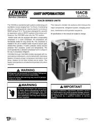
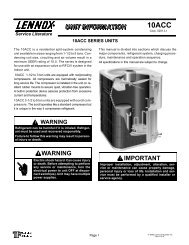
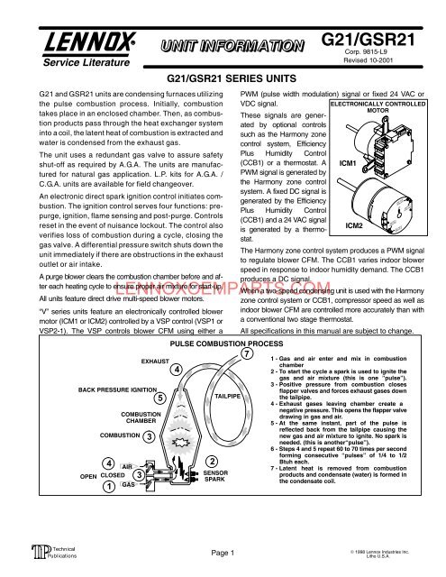
G21 <strong>and</strong> GSR21 units are condensing furnaces utilizing<br />
the pulse combustion process. Initially, combustion<br />
takes place in an enclosed chamber. Then, as combus<br />
tion products pass through the heat exchanger system<br />
into a coil, the latent heat of combustion is extracted <strong>and</strong><br />
water is condensed from the exhaust gas.<br />
The unit uses a redundant gas valve to assure safety<br />
shutoff as required by A.G.A. The units are manufac<br />
tured for natural gas application. L.P. kits for A.G.A. /<br />
C.G.A. units are available for field changeover.<br />
An electronic direct spark ignition control initiates com<br />
bustion. The ignition control serves four functions: pre<br />
purge, ignition, flame sensing <strong>and</strong> postpurge. Controls<br />
reset in the event of nuisance lockout. The control also<br />
verifies loss of combustion during a cycle, closing the<br />
gas valve. A differential pressure switch shuts down the<br />
unit immediately if there are obstructions in the exhaust<br />
outlet or air intake.<br />
A purge blower clears the combustion chamber before <strong>and</strong> af<br />
ter each heating cycle to ensure proper air mixture for startup.<br />
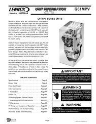
All units feature direct drive multispeed blower motors.<br />
V" series units feature an electronically controlled blower<br />
motor (ICM1 or ICM2) controlled by a VSP control (VSP1 or<br />
VSP2−1). The VSP controls blower CFM using either a<br />
G21/GSR21 SERIES UNITS<br />
LENNOXOEMPARTS.COM<br />
G21/GSR21<br />
Corp. 9815−L9<br />
Revised 10−2001<br />
PWM (pulse width modulation) signal or fixed 24 VAC or<br />
VDC signal.<br />
These signals are gener<br />
ated by optional controls<br />
such as the Harmony zone<br />
control system, Efficiency<br />
Plus Humidity Control<br />
(CCB1) or a thermostat. A<br />
PWM signal is generated by<br />
the Harmony zone control<br />
system. A fixed DC signal is<br />
generated by the Efficiency<br />
Plus Humidity Control<br />
(CCB1) <strong>and</strong> a 24 VAC signal<br />
is generated by a thermo<br />
stat.<br />
ELECTRONICALLY CONTROLLED<br />
MOTOR<br />
ICM1<br />
ICM2<br />
The Harmony zone control system produces a PWM signal<br />
to regulate blower CFM. The CCB1 varies indoor blower<br />
speed in response to indoor humidity dem<strong>and</strong>. The CCB1<br />
produces a DC signal.<br />
When a twospeed condensing unit is used with the Harmony<br />
zone control system or CCB1, compressor speed as well as<br />
indoor blower CFM are controlled more accurately than with<br />
a conventional two stage thermostat.<br />
All specifications in this <strong>manual</strong> are subject to change.<br />
PULSE COMBUSTION PROCESS<br />
7<br />
EXHAUST<br />
1 − Gas <strong>and</strong> air enter <strong>and</strong> mix in combustion<br />
chamber<br />
4<br />
2 − To start the cycle a spark is used to ignite the<br />
gas <strong>and</strong> air mixture (this is one "pulse").<br />
3 − Positive pressure from combustion closes<br />
BACK PRESSURE IGNITION<br />
flapper valves <strong>and</strong> forces exhaust gases down<br />
5<br />
TAILPIPE<br />
the tailpipe.<br />
4 − Exhaust gases leaving chamber create a<br />
negative pressure. This opens the flapper valve<br />
COMBUSTION<br />
drawing in gas <strong>and</strong> air.<br />
CHAMBER<br />
5 − At the same instant, part of the pulse is<br />
reflected back from the tailpipe causing the<br />
COMBUSTION<br />
3<br />
new gas <strong>and</strong> air mixture to ignite. No spark is<br />
needed. (this is anotherpulse").<br />
6 − Steps 4 <strong>and</strong> 5 repeat 60 to 70 times per second<br />
forming consecutive pulses" of 1/4 to 1/2<br />
4<br />
2<br />
Btuh each.<br />
AIR<br />
7 − Latent heat is removed from combustion<br />
OPEN CLOSED<br />
SENSOR<br />
3<br />
products <strong>and</strong> condensate (water) is formed in<br />
SPARK<br />
the condensate coil.<br />
1<br />
GAS<br />
Page 1<br />
© 1998 Lennox Industries Inc.<br />
Litho U.S.A.
General Page 1<br />
<strong>Parts</strong> Arrangement Page 3<br />
Specifications<br />
Blower Data<br />
TABLE OF CONTENTS<br />
Page 4−6<br />
Page 6−10<br />
Component Illustration Page 11<br />
I Application Page 12<br />
II Unit Components<br />
VSP1 Blower Control<br />
VSP2 Blower Control<br />
Ignition Control<br />
Page 12−36<br />
Page 15−16<br />
Page 17−19<br />
Page 21−24<br />
Blower Motor Q Units Page 29<br />
ICM1 <strong>and</strong> ICM2<br />
III Installation<br />
IV Maintenance<br />
V Unit Checkout<br />
VI Troubleshooting<br />
Page 30−36<br />
Page 36−44<br />
Page 45−46<br />
Page 46−53<br />
Page 54−56<br />
VII Troubleshooting Charts Page 57−68<br />
GC1 Ignition Control Page 57<br />
GC3 Ignition Control Page 58<br />
G891 Ignition Control Page 58<br />
Electrical Checkout Page 59<br />
Gas, <strong>Air</strong>, Spark Check Page 60<br />
Electrical Testing Page 61<br />
ICM2−VSP2 Page 62<br />
ICM1−VSP1<br />
Page 63−65<br />
Additional Charts<br />
Page 66−68<br />
VIII Wiring <strong>and</strong> Sequence of Operation<br />
G21Q<br />
Page 69−70<br />
GSR21Q<br />
Page 71−72<br />
G21V<br />
Page 73−74<br />
GSR21V<br />
Page 75−76<br />
G21Q W/ GC3<br />
Page 77−78<br />
G21Q W/ GC1<br />
Page 79−80<br />
GSR21Q W/ GC3<br />
Page 81−82<br />
GSR21Q W/ GC1<br />
Page 83−84<br />
G21V W/ GC1<br />
Page 85−86<br />
G21V W/ GC3<br />
Page 87−88<br />
GSR21V W/ GC1<br />
Page 89−90<br />
GSR21V W/ GC3<br />
Page 91−92<br />
Page 93−99<br />
LENNOXOEMPARTS.COM<br />
Jumper Summary Tables<br />
ELECTROSTATIC DISCHARGE (ESD)<br />
Precautions <strong>and</strong> Procedures<br />
CAUTION<br />
Electrostatic discharge can affect electronic com<br />
ponents. Take precautions during furnace installa<br />
tion <strong>and</strong> <strong>service</strong> to protect the furnace’s electronic<br />
controls. Precautions will help to avoid control ex<br />
posure to electrostatic discharge by putting the<br />
furnace, the control <strong>and</strong> the technician at the same<br />
electrostatic potential. Neutralize electrostatic<br />
charge by touching h<strong>and</strong> <strong>and</strong> all tools on an un<br />
painted unit surface, such as the gas valve or blow<br />
er deck, before performing any <strong>service</strong> procedure.<br />
Page 2
DIFFERENTIAL<br />
PRESSURE<br />
SWITCH<br />
LIMIT<br />
CONTROL<br />
PARTS ARRANGEMENT (G21 UPFLOW UNIT)<br />
HEAT EXCHANGER<br />
ASSEMBLY<br />
GAS VALVE<br />
IGNITION<br />
CONTROL<br />
AIR INTAKE<br />
CONNECTION<br />
EXPANSION<br />
TANK<br />
GAS FLAPPER VALVE<br />
& ORIFICE ASSEMBLY<br />
ICM1 BLOWER<br />
MOTOR<br />
AIR VALVE AND<br />
AIR HOUSING<br />
LOW VOLTAGE<br />
TERMINAL<br />
STRIP<br />
CONTROL<br />
BOX<br />
BLOWER<br />
G21Q SERIES<br />
BLOWER MOTOR<br />
DOOR<br />
INTERLOCK SWITCH<br />
LENNOXOEMPARTS.COM<br />
PARTS ARRANGEMENT (GSR21 DOWNFLOW HORIZONTAL UNIT)<br />
IGNITION CONTROL<br />
AIR INTAKE<br />
PVC CONNECTION<br />
ICM2 BLOWER<br />
MOTOR<br />
AVAILABLE ELECTRONICALLY<br />
CONTROLLED BLOWER MOTOR<br />
V" MODELS<br />
BLOWER<br />
COMPARTMENT<br />
LOW VOLTAGE<br />
TERMINAL STRIP<br />
DOOR INTERLOCK<br />
SAFETY SWITCH<br />
HEAT EXCHANGER<br />
ASSEMBLY<br />
AIR FLAPPER AND<br />
HOUSING<br />
CONTROL BOX<br />
EXHAUST OUTLET<br />
GAS VALVE<br />
PURGE BLOWER<br />
EXPANSION TANK<br />
Page 3
SPECIFICATIONS (units equipped with conventional multispeed blower motor)<br />
Model No. G21Q340 G21Q360 G21Q460<br />
Input Btuh 40,000 60,000 60,000<br />
Output Btuh 38,000 55,000 55,000<br />
*A.F.U.E. 96.2% 94.1% 94.1%<br />
California Seasonal Efficiency 90.7% 89.9% 88.8%<br />
Temperature rise range (°F) 35 65 40 70 35 65<br />
High static certified by A.G.A. (in wg.) .50 .50 .50<br />
Gas Piping Size Natural 1/2 1/2 1/2<br />
I.P.S. (in.) **LPG 1/2 1/2 1/2<br />
Vent/Intake air pipe size connection (in.) 2 2 2<br />
Condensate drain connection (in.) SDR11 1/2 1/2 1/2<br />
Blower wheel nominal diameter x width (in.) 10 x 8 10 x 8 11 x 9<br />
Blower motor hp 1/3 1/3 1/2<br />
Number <strong>and</strong> size of filters (in.) (1) 16 x 25 x 1 (1) 16 x 25 x 1 (1) 16 x 25 x 1<br />
Tons of cooling that can be added 11/2 3 11/2 3 21/2 4<br />
Electrical characteristics<br />
120 volts 60 hertz 1 phase (less than 12 amps) All models<br />
**LPG kit (optional) LB65810A LB65810B LB65810B<br />
External Filter Mounting Part No. LB81871CA LB81871CA LB81871CA<br />
Kit (optional) •Filter size (in.) (1) 16 x 25 x 1 (1) 16 x 25 x 1 (1) 16 x 25 x 1<br />
•Filter is not furnished with kit. Filter kit utilizes existing filter supplied with G21 unit.<br />
*Annual Fuel Utilization Efficiency based on D.O.E. test procedures <strong>and</strong> according to F.T.C. labeling regulations.<br />
Isolated combustion system rating for nonweatherized furnaces.<br />
**LPG kit must be ordered extra for field changeover.<br />
SPECIFICATIONS (units equipped with conventional multispeed blower motor)<br />
Model No. G21Q380 G21Q480 G21Q580 G21Q3100 G21Q4/5100<br />
LENNOXOEMPARTS.COM<br />
Input Btuh 80,000 80,000 80,000 100,000 100,000<br />
Output Btuh 73,000 73,000 74,000 93,000 95,000<br />
*A.F.U.E. 93.9% 93.9% 93.2% 94.9% 94.5%<br />
California Seasonal Efficiency 90.1% 88.9% 88.3% 90.8% 89.6%<br />
Temperature rise range (°F) 45 75 40 70 35 65 55 85 40 70<br />
High static certified by A.G.A. (in wg.) .50 .50 .50 .50 .50<br />
Gas Piping Size Natural 1/2 1/2 1/2 1/2 1/2<br />
I.P.S. (in.) **LPG 1/2 1/2 1/2 1/2 1/2<br />
Vent/Intake air pipe size connection (in.) 2 2 2 2 2<br />
Condensate drain connection (in.) SDR11 1/2 1/2 1/2 1/2 1/2<br />
Blower wheel nominal diameter x width (in.) 10 x 8 11 x 9 12 x 12 10 x 8 12 x 12<br />
Blower motor hp 1/3 1/2 3/4 1/2 3/4<br />
Number <strong>and</strong> size of filters (in.) (1) 16 x 25 x 1 (1) 16 x 25 x 1 (1) 20 x 25 x 1 (1) 20 x 25 x 1 (1) 20 x 25 x 1<br />
Tons of cooling that can be added 2 3 21/2 4 4 or 5 2 3 31/2 5<br />
Electrical characteristics<br />
120 volts 60 hertz 1 phase (less than 12 amps) All models<br />
**LPG kit (optional) LB65810B LB65810B LB65810B LB65810C LB65810C<br />
External Filter Mounting Part No. LB81871CA LB81871CA LB81871CB LB81871CB LB81871CB<br />
Kit (optional) •Filter size (in.) (1) 16 x 25 x 1 (1) 16 x 25 x 1 (1) 20 x 25 x 1 (1) 20 x 25 x 1 (1) 20 x 25 x 1<br />
•Filter is not furnished with kit. Filter kit utilizes existing filter supplied with G21 unit.<br />
*Annual Fuel Utilization Efficiency based on D.O.E. test procedures <strong>and</strong> according to F.T.C. labeling regulations.<br />
Isolated combustion system rating for nonweatherized furnaces.<br />
**LPG kit must be ordered extra for field changeover.<br />
Page 4
SPECIFICATIONS (contd.)<br />
SPECIFICATIONS (units equipped with conventional multispeed blower motor)<br />
Model No.<br />
GSR21Q350<br />
GSR21Q45<br />
0<br />
GSR21Q38<br />
0<br />
GSR21Q4/580<br />
GSR21Q4/5100<br />
Input Btuh 50,000 50,000 80,000 80,000 100,000<br />
Output Btuh 47,000 47,000 71,000 72,000 92,000<br />
*A.F.U.E. 94.8% 95.3% 91.7% 94.1% 92.0%<br />
California Seasonal Efficiency 89.7% 90.1% 87.6% 88.6% 87.3%<br />
Temperature rise range (°F) 30 60 25 55 40 70 30 60 45 75<br />
High static certified by A.G.A. (in wg.) .50 .50 .50 .50 .50<br />
Gas Piping Size Natural 1/2 1/2 1/2 1/2 1/2<br />
I.P.S. (in.) •LPG 1/2 1/2 1/2 1/2 1/2<br />
Vent/Intake air pipe size connection (in.) 2 2 2 2 2<br />
Condensate drain connection (in.) SDR11 1/2 1/2 1/2 1/2 1/2<br />
Blower wheel nominal diameter x width (in.) 10 x 8 10 x 10 10 x 10 12 x 12 12 x 12<br />
Blower motor hp 1/3 1/2 1/3 3/4 3/4<br />
Number <strong>and</strong> size of filters (in.) (1) 20 x 25 x 1<br />
Tons of cooling that can be added 11/2 3 31/2 4 2 3 31/2 5 31/2 5<br />
Electrical characteristics<br />
120 volts 60 hertz 1 phase (less than 12 amps) All models<br />
LPG kit (optional) **Furnished •LB65810C<br />
Optional Horizontal Support Frame Kit Ship. Weight<br />
LB56495CA (All Models) 18 lbs.<br />
Optional Downflow Additive Base Shipping Weight<br />
LB80639BB (All Models) 6 lbs.<br />
•LPG kit must be ordered extra for field changeover.<br />
*Annual Fuel Utilization Efficiency based on D.O.E. test procedures <strong>and</strong> according to F.T.C. labeling regulations.<br />
Isolated combustion system rating for nonweatherized furnaces.<br />
**LPG orifice furnished as st<strong>and</strong>ard with unit for field changeover. Convertible gas valve requires simple adjustment without adding any parts. See installation instructions.<br />
SPECIFICATIONS (units equipped with electronically controlled blower motor)<br />
LENNOXOEMPARTS.COM<br />
Model No. G21V360 G21V380 G21V580 G21V5100<br />
Input Btuh 60,000 80,000 80,000 100,000<br />
Output Btuh 55,000 73,000 74,000 95,000<br />
*A.F.U.E. 94.3% 94.5% 93.4% 94.5%<br />
California Seasonal Efficiency 92.5% 92.4% 90.9% 91.5%<br />
Temperature rise range (°F) 40 70 45 75 35 65 40 70<br />
High static certified by A.G.A. (in wg.) .80 .80 .80 .80<br />
Gas Piping Size Natural 1/2 1/2 1/2 1/2<br />
I.P.S. (in.) **LPG 1/2 1/2 1/2 1/2<br />
Vent/Intake air pipe size connection (in.) 2 2 2 2<br />
Condensate drain connection (in.) SDR11 1/2 1/2 1/2 1/2<br />
Blower wheel nominal diameter x width (in.) 10 x 8 10 x 8 111/2 x 9 111/2 x 9<br />
Blower motor hp 1/2 1/2 1 1<br />
Number <strong>and</strong> size of filters (in.) (1) 16 x 25 x 1 (1) 16 x 25 x 1 (1) 20 x 25 x 1 (1) 20 x 25 x 1<br />
Tons of cooling that can be added 11/2, 2, 21/2 or 3 2, 21/2 or 3 31/2, 4 or 5 31/2, 4 or 5<br />
Electrical characteristics 120V − 60hertz − 1 phase − 12.0 Amps Max 120V − 60hertz − 1 phase − 14.5 Amps Max<br />
External Filter Cabinet (furnished)<br />
•Filter size (in.)<br />
(1) 16 x 25 x 1 (1) 16 x 25 x 1 (1) 20 x 25 x 1 (1) 20 x 25 x 1<br />
**LPG kit (optional) LB65810B LB65810B LB65810B LB65810C<br />
•Filter is not furnished with cabinet. Filter cabinet utilizes existing filter supplied with G21V unit.<br />
*Annual Fuel Utilization Efficiency based on D.O.E. test procedures <strong>and</strong> according to F.T.C. labeling regulations.<br />
Isolated combustion system rating for nonweatherized furnaces.<br />
**LPG kit must be ordered extra for field changeover.<br />
Page 5
SPECIFICATIONS (contd.)<br />
SPECIFICATIONS (units equipped with electronically controlled blower motor)<br />
Model No. GSR21V380 GSR21V580 GSR21V5100<br />
Input Btuh 80,000 80,000 100,000<br />
Output Btuh 71,000 72,000 92,000<br />
*A.F.U.E. 94.5% 94.6% 92.0%<br />
California Seasonal Efficiency 92.5% 92.1% 89.7%<br />
Temperature rise range (°F) 40 70 30 60 45 75<br />
High static certified by A.G.A. (in wg.) .80 .80 .80<br />
Gas Piping Size Natural 1/2 1/2 1/2<br />
I.P.S. (in.) •LPG 1/2 1/2 1/2<br />
Vent/Intake air pipe size connection (in.) 2 2 2<br />
Condensate drain connection (in.) SDR11 1/2 1/2 1/2<br />
Blower wheel nominal diameter x width (in.) 10 x 8 111/2 x 9 111/2 x 9<br />
Blower motor hp 1/2 1 1<br />
Number <strong>and</strong> size of filters (in.) (1) 20 x 25 x 1<br />
Tons of cooling that can be added 2 3 31/2 5 31/2 5<br />
Electrical characteristics<br />
120V − 60hertz − 1 phase<br />
12.0 Amps Max<br />
120V − 60hertz − 1 phase − 14.5 Amps Max<br />
•LPG kit (optional) **Furnished LB65810C<br />
Optional Horizontal Support Frame Kit Ship. Weight<br />
LB56495CA (All Models) 18 lbs.<br />
Optional Downflow Additive Base Shipping Weight<br />
LB80639BB (All Models) 6 lbs.<br />
LENNOXOEMPARTS.COM<br />
•LPG kit must be ordered extra for field changeover.<br />
*Annual Fuel Utilization Efficiency based on D.O.E. test procedures <strong>and</strong> according to F.T.C. labeling regulations.<br />
Isolated combustion system rating for nonweatherized furnaces.<br />
**LPG orifice furnished as st<strong>and</strong>ard with unit for field changeover. Convertible gas valve requires simple adjustment without adding any parts. See installation instructions.<br />
BLOWER DATA<br />
(units equipped with conventional multispeed blower motor)<br />
External Static<br />
Pressure<br />
(in. wg)<br />
G21Q340, G21Q360 AND G21Q380<br />
BLOWER PERFORMANCE<br />
<strong>Air</strong> Volume @ Various Speeds<br />
High Medium Low<br />
0 1585 1392 920<br />
.05 1558 1364 917<br />
.10 1533 1354 915<br />
.15 1505 1335 912<br />
.20 1477 1315 905<br />
.25 1447 1294 893<br />
.30 1418 1272 887<br />
.40 1355 1225 858<br />
.50 1282 1164 803<br />
NOTE All cfm data is measured external to unit with the air filter in place.<br />
ExternalStatic<br />
Pressure<br />
(in. wg)<br />
G21Q580 BLOWER PERFORMANCE<br />
<strong>Air</strong> Volume (cfm) @ Various Speeds<br />
High MedHigh Medium MedLow Low<br />
0 2460 2350 2155 1900 1695<br />
.05 2430 2310 2130 1875 1675<br />
.10 2395 2275 2100 1855 1655<br />
.15 2355 2240 2065 1825 1625<br />
.20 2315 2205 2035 1800 1600<br />
.25 2275 2175 1995 1780 1570<br />
.30 2235 2130 1960 1740 1540<br />
.40 2155 2055 1880 1675 1480<br />
.50 2070 1970 1790 1605 1410<br />
.60 1980 1890 1710 1540 1345<br />
NOTE All cfm data is measured external to unit with the air filter in place.<br />
Page 6
External Static<br />
Pressure<br />
(in. wg)<br />
BLOWER DATA (contd.) (units equipped with conventional multispeed blower motor)<br />
G21Q460 AND G21Q480<br />
BLOWER PERFORMANCE<br />
<strong>Air</strong> Volume @ Various Speeds<br />
High Medium Low<br />
0 1793 1295 1050<br />
.05 1770 1290 1050<br />
.10 1747 1285 1050<br />
.15 1724 1280 1050<br />
.20 1700 1275 1050<br />
.25 1675 1267 1050<br />
.30 1648 1258 1050<br />
.40 1585 1233 1036<br />
.50 1517 1193 1012<br />
NOTE All cfm data is measured external to unit with the air filter in place.<br />
G21Q3100 BLOWER PERFORMANCE<br />
External Static<br />
Pressure<br />
(in. wg)<br />
G21Q4/5100 BLOWER PERFORMANCE<br />
<strong>Air</strong> Volume @ Various Speeds<br />
High Medium Low<br />
0 1850 1660 1500<br />
.05 1805 1635 1470<br />
.10 1760 1610 1440<br />
.15 1720 1575 1420<br />
.20 1680 1540 1400<br />
.25 1635 1505 1375<br />
.30 1590 1470 1350<br />
.40 1500 1400 1290<br />
.50 1400 1320 1220<br />
.60 1290 1230 1140<br />
NOTE All cfm data is measured external to unit with the air filter in place.<br />
ExternalStatic<br />
Pressure<br />
(in. wg)<br />
<strong>Air</strong> Volume (cfm) @ Various Speeds<br />
High MedHigh Medium MedLow Low<br />
0 2450 2340 2140 1910 1690<br />
.05 2420 2310 2110 1880 1670<br />
.10 2390 2270 2080 1860 1640<br />
.15 2350 2240 2050 1830 1620<br />
.20 2320 2210 2020 1800 1590<br />
.25 2280 2170 1990 1770 1570<br />
LENNOXOEMPARTS.COM<br />
.30 2250 2140 1960 1740 1540<br />
.40 2180 2060 1890 1680 1480<br />
.50 2100 1980 1810 1610 1420<br />
.60 2005 1890 1740 1530 1350<br />
NOTE All cfm data is measured external to unit with the air filter in place.<br />
GSR21Q350 BLOWER PERFORMANCE<br />
GSR21Q380 BLOWER PERFORMANCE<br />
External Static<br />
Pressure<br />
(in. wg)<br />
<strong>Air</strong> Volume (cfm) @ Various Speeds<br />
High MedHigh MedLow Low<br />
0 1640 1405 1070 875<br />
.05 1620 1390 1065 870<br />
.10 1595 1375 1060 865<br />
.15 1570 1360 1055 860<br />
.20 1545 1345 1045 855<br />
.25 1520 1325 1035 850<br />
.30 1490 1305 1025 840<br />
.40 1430 1260 995 810<br />
.50 1365 1200 960 775<br />
.60 1285 1135 910 735<br />
.70 1195 1055 840 <br />
.80 1085 955 755 <br />
NOTE All cfm data is measured external to unit with the air filter in place.<br />
External Static<br />
Pressure<br />
(in. wg)<br />
<strong>Air</strong> Volume @ Various Speeds<br />
High Medium Low<br />
0 1735 1455 1095<br />
.05 1720 1445 1090<br />
.10 1700 1435 1085<br />
.15 1675 1420 1080<br />
.20 1640 1405 1070<br />
.25 1615 1385 1060<br />
.30 1585 1355 1045<br />
.40 1520 1290 995<br />
.50 1440 1210 930<br />
.60 1330 1120 870<br />
.70 1180 1015 <br />
.80 1035 900 <br />
NOTE All cfm data is measured external to unit with the air filter in place.<br />
Page 7
BLOWER DATA (contd.) (units equipped with conventional multispeed blower motor)<br />
GSR21Q450 BLOWER PERFORMANCE<br />
GSR21Q4/580 BLOWER PERFORMANCE<br />
External Static<br />
Pressure<br />
(in. wg)<br />
<strong>Air</strong> Volume (cfm) @ Various Speeds<br />
High MedHigh MedLow Low<br />
0 1935 1725 1530 1225<br />
.05 1900 1695 1515 1220<br />
.10 1865 1665 1490 1210<br />
.15 1825 1630 1465 1195<br />
.20 1790 1595 1435 1175<br />
.25 1745 1560 1400 1140<br />
.30 1700 1520 1365 1105<br />
.40 1585 1420 1285 1030<br />
.50 1470 1320 1200 975<br />
.60 1360 1215 1115 920<br />
.70 1235 1115 1030 <br />
.80 1105 1000 930 <br />
ExternalStatic<br />
Pressure<br />
(in. wg)<br />
NOTE All cfm data is measured external to unit with the air filter in place.<br />
NOTE All cfm data is measured external to unit with the air filter in place.<br />
GSR21Q4/5100 BLOWER PERFORMANCE<br />
ExternalStatic<br />
Pressure<br />
(in. wg)<br />
<strong>Air</strong> Volume (cfm) @ Various Speeds<br />
High MedHigh Medium MedLow Low<br />
0 2275 2140 1940 1725 1520<br />
.05 2245 2110 1915 1700 1490<br />
.10 2215 2075 1885 1675 1465<br />
.15 2185 2040 1860 1645 1435<br />
LENNOXOEMPARTS.COM<br />
.20 2150 2005 1830 1620 1410<br />
.25 2115 1970 1805 1590 1380<br />
.30 2075 1935 1775 1560 1350<br />
.40 1990 1870 1710 1500 1290<br />
.50 1925 1800 1645 1435 1235<br />
.60 1835 1730 1570 1370 1175<br />
.70 1760 1650 1490 1300 <br />
.80 1675 1570 1400 1225 <br />
NOTE All cfm data is measured external to unit with the air filter in place.<br />
<strong>Air</strong> Volume (cfm) @ Various Speeds<br />
High MedHigh Medium MedLow Low<br />
0 2355 2205 1965 1740 1520<br />
.05 2325 2175 1940 1715 1495<br />
.10 2290 2150 1920 1695 1475<br />
.15 2255 2115 1890 1670 1450<br />
.20 2220 2085 1860 1645 1425<br />
.25 2185 2050 1830 1620 1400<br />
.30 2150 2020 1800 1595 1375<br />
.40 2080 1950 1745 1540 1320<br />
.50 2000 1880 1680 1475 1260<br />
.60 1915 1805 1615 1410 1195<br />
.70 1825 1720 1540 1330 <br />
.80 1730 1635 1460 1240 <br />
Units Equipped With an Electronically Controlled Blower Motor ICM2<br />
G21V3−60/80 BLOWER MOTOR PERFORMANCE<br />
(For Static Pressure 0.0" to 0.8" w.g.)<br />
ADJUST<br />
LOW SPEED HIGH (COOL) SPEED HEAT SPEED<br />
JUMPER<br />
VSP2−1 JUMPER POSITION VSP2−1 JUMPER POSITION VSP2−1 JUMPER POSITION<br />
SETTING 1 2 3 4 1 2 3 4 1 2 3 4<br />
+ 540 700 830 1000 1150 1260 1400 1410 1150 1250 1350 1420<br />
NORM 490 630 740 880 1040 1140 1240 1265 1030 1140 1220 1300<br />
− 440 560 670 800 940 1030 1140 1160 920 1020 1100 1190<br />
NOTE: ADJUST position on JPB1 (NORM", +", or −") determines the row of CFM available to use.<br />
NOTE All air data is measured external to the unit with the air filter in place.<br />
Blower maintains a constant CFM throughout a range of varying static pressures.<br />
Page 8
BLOWER DATA (contd.) (units equipped with an electronically controlled blower motor ICM2)<br />
G21V5−80/100 BLOWER MOTOR PERFORMANCE<br />
(For Static Pressure 0.0" to 0.8" w.g.)<br />
ADJUST<br />
LOW SPEED HIGH (COOL) SPEED HEAT SPEED<br />
JUMPER<br />
VSP2−1 JUMPER POSITION VSP2−1 JUMPER POSITION VSP2−1 JUMPER POSITION<br />
SETTING 1 2 3 4 1 2 3 4 1 2 3 4<br />
+ 800 1050 1410 1620 1710 2030 2270* 2270* 1900 2140 2270* 2270*<br />
NORM 720 950 1280 1500 1570 1850 2100 2220 1700 1940 2080 2200<br />
− 620 850 1120 1310 1420 1650 1860 1990 1520 1730 1860 1940<br />
NOTE: ADJUST position on JPB1 (NORM", +", or −") determines the row of CFM available to use.<br />
*2300 CFM @ 0.2" w.g.; 2250 CFM @ 0.5" w.g.; 2200 CFM @ 0.8" w.g.<br />
NOTE All air data is measured external to the unit with the air filter in place.<br />
Blower maintains a constant CFM throughout a range of varying static pressures.<br />
GSR21V3−80 BLOWER MOTOR PERFORMANCE<br />
(For Static Pressure 0.0" to 0.8" w.g.)<br />
ADJUST<br />
LOW SPEED HIGH (COOL) SPEED HEAT SPEED<br />
JUMPER<br />
VSP2−1 JUMPER POSITION VSP2−1 JUMPER POSITION VSP2−1 JUMPER POSITION<br />
SETTING 1 2 3 4 1 2 3 4 1 2 3 4<br />
+ 520 670 800 960 1110 1220 1340 1420 1110 1210 1310 1420<br />
NORM 480 600 740 880 1070 1160 1270 1300 1000 1100 1200 1280<br />
− 420 550 650 770 950 1040 1150 1170 900 1000 1100 1160<br />
LENNOXOEMPARTS.COM<br />
NOTE: ADJUST position on JPB1 (NORM", +", or −") determines the row of CFM available to use.<br />
NOTE All air data is measured external to the unit with the air filter in place.<br />
Blower maintains a constant CFM throughout a range of varying static pressures.<br />
GSR21V5−80/100 BLOWER MOTOR PERFORMANCE<br />
(For Static Pressure 0.0" to 0.8" w.g.)<br />
ADJUST<br />
LOW SPEED HIGH (COOL) SPEED HEAT SPEED<br />
JUMPER<br />
VSP2−1 JUMPER POSITION VSP2−1 JUMPER POSITION VSP2−1 JUMPER POSITION<br />
SETTING 1 2 3 4 1 2 3 4 1 2 3 4<br />
+ 860 1100 1460 1740 1800 2090 2100* 2100* 1930 2100* 2100* 2100*<br />
NORM 770 1020 1390 1580 1720 1990 2100* 2100* 1800 2000 2100* 2100*<br />
− 680 900 1180 1400 1450 1690 1940 2040 1580 1780 1920 2010<br />
NOTE: ADJUST position on JPB1 (NORM", +", or −") determines the row of CFM available to use.<br />
*2200 CFM @ 0.2" w.g.; 2100 CFM @ 0.5" w.g.; 2000 CFM @ 0.8" w.g.<br />
NOTE All air data is measured external to the unit with the air filter in place.<br />
Blower maintains a constant CFM throughout a range of varying static pressures.<br />
Page 9
Units Equipped With an Electronically Controlled Blower Motor ICM1<br />
G21V360, G21V380 BLOWER PERFORMANCE<br />
FACTORY BLOWER SPEED SETTINGS<br />
G21V360<br />
G21V380<br />
Low Speed Heat/Cool tap 2 Low Speed Heat/Cool tap 2<br />
High Speed Cooling tap 11 High Speed Cooling tap 11<br />
High Speed Heat tap 6 High Speed Heat tap 7<br />
External Static<br />
<strong>Air</strong> Volume (cfm) @ Various Speeds<br />
Pressure<br />
(in. wg.)<br />
Tap 1 Tap 2 Tap 3 Tap 4 Tap 5 Tap 6 Tap 7 Tap 8 Tap 9 Tap 10 Tap 11<br />
0<br />
thru<br />
490 635 760 880 1030 1140 1220 1345 1420 1420<br />
.80<br />
NOTE All air data is measured external to the unit with the air filter in place.<br />
*Blower maintains a constant CFM throughout a range of varying static pressures.<br />
G21V580, G21V5100 BLOWER PERFORMANCE<br />
FACTORY BLOWER SPEED SETTINGS<br />
G21V580<br />
G21V5100<br />
Low Speed Heat/Cool tap 2 Low Speed Heat/Cool tap 2<br />
High Speed Cooling tap 11 High Speed Cooling tap 11<br />
High Speed Heat tap 6 High Speed Heat tap 7<br />
External Static<br />
<strong>Air</strong> Volume (cfm) @ Various Speeds<br />
Pressure<br />
(in. wg.)<br />
0<br />
thru<br />
.80<br />
Tap 1 Tap 2 Tap 3 Tap 4 Tap 5 Tap 6 Tap 7 Tap 8 Tap 9 Tap 10 Tap 11<br />
770 1015 1305 1510 1685 1820 2010 2050 2100 2100<br />
NOTE All air data is measured external to the unit with the air filter in place.<br />
*Blower maintains a constant CFM throughout a range of varying static pressures.<br />
External Static<br />
GSR21V380 BLOWER PERFORMANCE<br />
LENNOXOEMPARTS.COM<br />
FACTORY BLOWER SPEED SETTINGS<br />
GSR21V380<br />
Low Speed Heat/Cool tap 3<br />
High Speed Cooling tap 11<br />
High Speed Heat tap 7<br />
<strong>Air</strong> Volume (cfm) @ Various Speeds<br />
Pressure<br />
(in. wg.)<br />
0<br />
thru<br />
.80<br />
Tap 1 Tap 2 Tap 3 Tap 4 Tap 5 Tap 6 Tap 7 Tap 8 Tap 9 Tap 10 Tap 11<br />
480 655 790 960 1120 1220 1365 1460 1460<br />
NOTE All air data is measured external to the unit with the air filter in place.<br />
*Blower maintains a constant CFM throughout a range of varying static pressures.<br />
External Static<br />
GSR21V580, GSR21V5100 BLOWER PERFORMANCE<br />
FACTORY BLOWER SPEED SETTINGS<br />
GSR21V580<br />
GSR21V5100<br />
Low Speed Heat/Cool tap 2 Low Speed Heat/Cool tap 2<br />
High Speed Cooling tap 11 High Speed Cooling tap 11<br />
High Speed Heat tap 6 High Speed Heat tap 7<br />
<strong>Air</strong> Volume (cfm) @ Various Speeds<br />
Pressure<br />
(in. wg.)<br />
0<br />
thru<br />
.80<br />
Tap 1 Tap 2 Tap 3 Tap 4 Tap 5 Tap 6 Tap 7 Tap 8 Tap 9 Tap 10 Tap 11<br />
890 990 1230 1425 1605 1735 1900 2015 2090 2090<br />
NOTE All air data is measured external to the unit with the air filter in place.<br />
*Blower maintains a constant CFM throughout a range of varying static pressures.<br />
Page 10
UNIT COMPONENTS UPFLOW Q" UNITS<br />
DIFFERENTIAL PRESSURE<br />
SWITCH<br />
LIMIT CONTROL<br />
AIR INTAKE PVC CONNECTION<br />
GAS VALVE<br />
IGNITION CONTROL<br />
AIR FLAPPER VALVE<br />
INSULATION<br />
SPARK PLUG & SENSOR ACCESS<br />
PANEL<br />
TERMINAL STRIP<br />
TB1<br />
EXPANSION TANK<br />
GAS FLAPPER VALVE<br />
& ORIFICE ASSEMBLY<br />
HEATING COMPARTMENT<br />
CONTROL BOX<br />
PURGE BLOWER<br />
EXHAUST OUTLET<br />
DOOR INTERLOCK SAFETY SWITCH<br />
BLOWER<br />
LENNOXOEMPARTS.COM<br />
(ICM2 SHOWN WITH VSP2−1)<br />
UNIT COMPONENTS HORIZONTAL/REVERSE FLOW V" UNITS<br />
SPARK PLUG<br />
& SENSOR ACCESS<br />
PANEL<br />
HEATING<br />
COMPARTMENT<br />
IGNITION<br />
CONTROL<br />
PURGE BLOWER<br />
AIR INTAKE PVC CONNECTION<br />
DIFFERENTIAL PRESSURE<br />
SWITCH<br />
TERMINAL STRIP TB1<br />
VSP21<br />
CONTROL BOARD<br />
BLOWER<br />
INSULATION<br />
AIR FLAPPER<br />
VALVE<br />
GAS FLAPPER VALVE<br />
& ORIFICE ASSEMBLY<br />
MODULATION/LIMIT<br />
CONTROL<br />
EXPANSION<br />
TANK<br />
GAS VALVE<br />
EXHAUST<br />
OUTLET<br />
CONTROL<br />
BOX<br />
DOOR INTERLOCK<br />
SAFETY SWITCH<br />
Page 11
I − APPLICATION<br />
G21/GSR21 unit input range covers 40,000 through 100,000<br />
Btuh. See specifications table.<br />
G21/GSR21 models use the same cabinet size as the ex<br />
istingG14/GSR14furnaceline.Allunitsinthe<br />
G21/GSR21 series use direct drive blowers <strong>and</strong> accept<br />
cooling coils in nominal tonnages up to 5 tons for the 80,<br />
100. Consult the Engineering H<strong>and</strong>book for proper sizing.<br />
Slab filters are used for either bottom or side return air in<br />
G21 models <strong>and</strong> top return air in GSR21 models.<br />
II − UNIT COMPONENTS<br />
A − Control Box (Figures 1 <strong>and</strong> 2)<br />
The G21 control box is located below the air intake chamber.<br />
40, 60 <strong>and</strong> 80 control boxes are designed to open over the<br />
exhaust PVC line when the unit is set up for righth<strong>and</strong> dis<br />
charge of exhaust. 100 control boxes are designed to open<br />
over the exhaust PVC line when the unit is set up for lefth<strong>and</strong><br />
discharge of exhaust.<br />
The GSR21 control box is located in the lower righth<strong>and</strong><br />
corner of the heating compartment in horizontal installa<br />
tions <strong>and</strong> in the upper righth<strong>and</strong> corner of the heating<br />
compartment in reverse flow applications.<br />
G21Q CONTROL BOX<br />
FAN TIMING CONTROL<br />
(A28)<br />
TRANSFORMER T1<br />
TERMINAL STRIP TB1<br />
G21V CONTROL BOX<br />
GROUNDING<br />
LUG<br />
TERMINAL<br />
BLOCK<br />
TB2<br />
INDOOR BLOWER<br />
RELAY K3<br />
GSR21Q CONTROL BOX<br />
TERMINAL<br />
STRIP<br />
TB1<br />
TERMINAL<br />
BLOCK<br />
TB2<br />
GROUNDING LUG<br />
FAN TIMING CONTROL<br />
(A28)<br />
INDOOR<br />
DOOR INTERLOCK<br />
BLOWER<br />
SAFETY SWITCH<br />
RELAY (K3)<br />
(S51)<br />
TRANSFORMER<br />
T1<br />
GSR21V CONTROL BOX<br />
TERMINAL STRIP<br />
TB1<br />
TERMINAL BLOCK<br />
TB2<br />
ACCESSORY<br />
RELAY K109<br />
TRANSFORMER<br />
T1<br />
FIGURE 1<br />
LENNOXOEMPARTS.COM<br />
GROUNDING LUG<br />
DOOR INTERLOCK<br />
SAFETY SWITCH<br />
(S51)<br />
TRANSFORMER<br />
T1<br />
TERMINAL BLOCK TB2<br />
ACCESSORY<br />
RELAY K109<br />
GROUNDING<br />
LUG<br />
TERMINAL<br />
STRIP TB1<br />
FIGURE 2<br />
1 − Control Transformer T1<br />
A transformer (T1) located inside the control box provides<br />
power to the low voltage section of the unit. Transformers are<br />
rated at 30VA for Q" models <strong>and</strong> 50VA for V" models with a<br />
120V primary <strong>and</strong> 24V secondary.<br />
2 − Transformer Fuse F1<br />
Transformer T1 is protected by a fuse F1. See table 1 for fuse<br />
ratings. The fuse is located on the TB1 terminal strip.<br />
TABLE 1<br />
TRANSFORMER FUSE<br />
APPLICATION F1<br />
FUSE RATING<br />
V" MODELS<br />
Q" MODELS<br />
3 AMP MDX SLOW BLOW<br />
2 AMP AGC FAST BLOW<br />
Page 12
3 − Low Voltage Terminal Strip TB1<br />
A low voltage terminal strip (TB1) with thermostat markings is<br />
located outside the control box. See figures 3, 4 <strong>and</strong> 5.<br />
W1<br />
W2<br />
R<br />
Q" SERIES TERMINAL STRIP TB1<br />
FUSE 2 AMP AGC FAST<br />
BLOW<br />
R W Y G C<br />
FIGURE 3<br />
R24VAC OUTPUT<br />
WHEATING DEMAND INPUT<br />
YCOOLING WIRING<br />
GBLOWER DEMAND INPUT<br />
CCOMMON<br />
*Y is used as a terminal block to<br />
connect the outdoor unit to the<br />
thermostat. It makes no internal<br />
connection to unit controls.<br />
V" SERIES IMC1 TERMINAL STRIP TB1<br />
G Y1 Y2<br />
DS<br />
C<br />
HB<br />
FUSE<br />
3 AMP MDX SLOW BLOW<br />
R24VAC OUTPUT<br />
W11st STAGE HEATING DEMAND INPUT<br />
W22nd STAGE HEATING DEMAND INPUT<br />
GBLOWER DEMAND INPUT<br />
Y11st STAGE COOLING CONNECTION<br />
Y22nd STAGE COOLING CONNECTION<br />
DSPWM, AC OR DC INPUT<br />
CCOMMON 24 VAC<br />
HBSENSING OUTPUT FOR HEATING<br />
BLOWER<br />
*Y is used as a terminal block to connect the<br />
outdoor unit to the thermostat. It makes no<br />
internal connection to unit controls.<br />
FIGURE 4<br />
V" SERIES IMC2 TERMINAL STRIP TB1<br />
G R C<br />
NM<br />
W1<br />
W2<br />
DS<br />
LENNOXOEMPARTS.COM<br />
FIGURE 5<br />
Y1<br />
Y2<br />
FUSE<br />
3 AMP MDX SLOW BLOW<br />
The following terminal designations are unique to V" se<br />
ries with the IMC1 motor:<br />
R" This signal provides 24VAC to the thermostat <strong>and</strong>, in<br />
zoning applications, to the zone control.<br />
DS " This is the speed regulation input that switches the<br />
blower from LOW to HIGH speed in cooling mode. DS is<br />
the PWM (pulse width modulation) input in zoning ap<br />
plications. When used with the CCB1 it is a 1217VDC<br />
signal. When used without the CCB or Harmony it is a<br />
24 VAC signal from the thermostat.<br />
HB" This is an output signal, to tell the zone control when<br />
the electronically controlled blower is energized from<br />
either a heating dem<strong>and</strong> or a tripped secondary limit.<br />
The following terminal designations are unique to V" series<br />
units with the IMC2 motor:<br />
R" This signal provides 24VAC to the thermostat <strong>and</strong>, in Har<br />
mony II zoning applications, to the control center.<br />
DS" This is the speed regulation input that switches<br />
the blower from LOW to HIGH speed, in cooling<br />
mode. DS is the PWM (pulse width modulation) in<br />
put in zoning applications that use Harmony II zon<br />
ing system.<br />
NM" This terminal is used for non−zoning (Non−Harmony),<br />
non−modulating applications where heat exchanger mod<br />
ulation is NOT desired. The heat dem<strong>and</strong> from the ther<br />
mostat should be wired to this terminal instead of W1.<br />
CAUTION<br />
For units with the IMC2 motor do not connect the<br />
heat dem<strong>and</strong> wire to both the W1 <strong>and</strong> the NM ter<br />
minals. Damage to the unit will occur. Use the W1<br />
terminal for zoning (Harmony) applications <strong>and</strong><br />
the NM terminal for non−zoning (Non−Harmony)<br />
applications.<br />
W1" This terminal is used for zoning (Harmony) modulating<br />
applications where heat exchanger modulation IS de<br />
sired. This terminal is also used for the first stage of a two−<br />
stage heating application.<br />
W2" This terminal is used for two−stage heating. Two−stage<br />
heating is not available when using the non−modulating<br />
NM terminal.<br />
For field wiring to terminal strips see figures 3, 4 <strong>and</strong> 5. See<br />
tables 2 <strong>and</strong> 3 for jumper connections.<br />
TABLE 2<br />
IMC1 MOTOR<br />
TB1 TERMINAL STRIP JUMPERS V" MODELS<br />
APPLICATION<br />
JUMPERS REQUIRED<br />
Single Stage <strong>Heating</strong><br />
HB" Jumpered to W2"<br />
SingleSpeed Compressor,<br />
DS" Jumpered to G"<br />
No CCB1, Without Harmony<br />
TwoSpeed Compressor, No<br />
DS" Jumpered to Y2"<br />
CCB1, Without Harmony<br />
CCB1 With SingleSpeed or Two No Jumpers Required*<br />
Speed Compressor, Without Harmony<br />
*Never Jumper Y2" to DS" when a CCB1 control is used.<br />
Damage to the CCB1 will occur.<br />
TABLE 3<br />
IMC2 MOTOR<br />
TB1 TERMINAL STRIP JUMPERS V" MODELS<br />
APPLICATION<br />
JUMPERS REQUIRED<br />
Single Stage <strong>Heating</strong><br />
See Figure 13<br />
For Pin Setting<br />
SingleSpeed Compressor,<br />
DS" Jumpered to G"<br />
No CCB1, Without Harmony<br />
TwoSpeed Compressor, No<br />
CCB1, Without Harmony<br />
CCB1 With SingleSpeed or Two<br />
Speed Compressor, Without Harmony<br />
*Never Jumper Y2" to DS" when a CCB1 control is used.<br />
Damage to the CCB1 will occur.<br />
DS" Jumpered to Y2"<br />
No Jumpers Required*<br />
NOTE − For single stage heat application with the IMC2 mo<br />
tor, VSP2−1 will have a selector pin for single or second<br />
stage heating. See figure 13.<br />
Refer to tables 18 through 22 for a complete listing of all jump<br />
ers used.<br />
Page 13
If a two speed condensing unit is used <strong>and</strong> Harmony or CCB1<br />
is not used jumper DS to Y2. The blower will operate on the<br />
low speed heat/cool tap during first stage cooling (low speed<br />
compressor). During second stage cooling (high speed com<br />
pressor), the blower will operate on the high speed cooling tap.<br />
If a single speed condensing unit <strong>and</strong> no Harmony or CCB1 is<br />
used, jumper DS to G. The blower will operate on the high<br />
speed cooling tap during the cooling mode.<br />
CAUTION<br />
Never jumper Y2" to DS" if a CCB1 control is<br />
used. Damage to the CCB1 control will occur.<br />
IMPORTANT<br />
Y2" must be jumpered to DS" in two−speed, non−<br />
zoned application when CCB1 is not used.<br />
4 − Terminal Block TB2 (Figure 6)<br />
Line voltage is routed to the unit through a power supply termi<br />
nal block (TB2) located inside the control box. The terminal<br />
block is energized at all times.<br />
For GC1 equipped units Watchguard is enabled with a<br />
heating dem<strong>and</strong>. After one hour (unit locked out or run<br />
ning) of continuous thermostat dem<strong>and</strong>, watchguard<br />
opens for two minutes then closes remaking thermostat<br />
dem<strong>and</strong> W1. This resets electronic ignition control A3.<br />
After this break, a thermostat de WATCHGUARD<br />
CONTROL BOARD<br />
m<strong>and</strong> for heat will allow the unit to<br />
(A18)<br />
fire. If ignition is not successful<br />
unit lockout occurs. If successful<br />
the unit operates. Lockouts are<br />
usually attributed to low gas line<br />
pressure. For units equipped with<br />
a GC3 or Johnson ignition con FIGURE 7<br />
trol, the Watchguard is enabled only after the unit locks<br />
out because of failed ignition attempts (five tries). The<br />
watchguard will then break <strong>and</strong> remake thermostat de<br />
m<strong>and</strong> after one hour.<br />
LENNOXOEMPARTS.COM<br />
In Q" units the accessory terminal (ACC) is energized any<br />
time there is a blower dem<strong>and</strong>. In V" units the accessory ter<br />
minal is energized by the VSP control <strong>and</strong> is powered when<br />
the blower is running.<br />
The accessory terminal can be used for accessories such as<br />
an electronic air cleaner.<br />
TERMINAL BLOCK TB2<br />
ACC<br />
L1<br />
FIGURE 6<br />
5 − K3 Indoor Blower Relay Q" Models Only<br />
A doublepole, doublethrow indoor blower relay is located in<br />
side the control box to provide power to the blower. K3 relay<br />
contacts also control the 120V accessory terminal located on<br />
terminal strip TB2.<br />
N<br />
6 − Watchguard Control Board (A18)<br />
GC1 Control Only<br />
The watchguard control board is illustrated in figure 7.<br />
Watchguard serves as an automatic electronic ignition<br />
reset device. Watchguard is a N.C. SPST selfresetting<br />
timer wired in series with W1 thermostat dem<strong>and</strong>. It is<br />
built into the ignition control on all units equipped with<br />
GC3 or Johnson ignition control. On GC1 equipped<br />
units it is externally mounted.<br />
7 − Fan Timing Control A28 Q"Units Only<br />
(Figure 8)<br />
A fan timing control<br />
(A28) located in the con<br />
trol box is used in Q"<br />
models to regulate fan<br />
on <strong>and</strong> fanoff timings.<br />
Fanon timing is the<br />
amount of time that the<br />
unit operates in a heat<br />
ing dem<strong>and</strong> without the<br />
FIGURE 8<br />
blower running during initial start up. Fanoff timing is the<br />
amount of time that the blower continues to run after heating<br />
dem<strong>and</strong> has been terminated. Fan timing control part number<br />
51K4601 (figure 8) has a factory set fan−on time of 45 sec<br />
onds <strong>and</strong> is adjustable from 30 to 60 seconds. Fan−off timing is<br />
factory set at180 seconds <strong>and</strong> is adjustable from 120 to 240<br />
seconds. Fan timing control with early part number 76H31 has<br />
a fanon timing set at 45 seconds <strong>and</strong> is not adjustable. Fan<br />
timing control with part number 97H03 <strong>and</strong> 79J65 has an ad<br />
justable fanon timing from 30 to 60 seconds. Fanoff timing is<br />
factory set at 180 seconds <strong>and</strong> is adjustable from 120 through<br />
240 seconds. During fanoff timing blower operates on low<br />
speed heat/cool tap.<br />
Page 14
8 − K9 Isolation (Heat) Relay<br />
Q" Models Only<br />
Fan timing control (A28) with part number 79J65 con<br />
tains a singlepole, singlethrow isolation relay (K9).<br />
When there is a heat dem<strong>and</strong> through W1, K9 is ener<br />
gized closing the normally open contacts K91 in the<br />
ignition circuit. The addition of an isolation relay in the<br />
W1 circuit will eliminate electrical noise feeding from the<br />
electronic thermostat back to the electronic ignition<br />
control.<br />
9 − K109 Accessory Relay V" Models Only<br />
G21V−5 to −8 & GSR21V−10 to −15<br />
A singlepole, singlethrow accessory relay is located inside<br />
the control box to provide power to additional accessories<br />
which may be used with the G21V / GSR21V.<br />
10 − VSP1 Blower Control Board (A24)<br />
V" Models Only G21V−1 to −3 &<br />
GSR21V−1 to −9 (Figure 9)<br />
VSP1 BLOWER CONTROL BOARD (A24)<br />
FRONT VIEW<br />
J46<br />
12 9 6<br />
4<br />
OUTPUT<br />
3<br />
PLUG<br />
1<br />
DS3 DS2 DS1<br />
1<br />
DIAGNOSTIC<br />
LEDS<br />
120V<br />
ACCESSORY<br />
TERMINAL<br />
L1 LINE<br />
VOLTAGE<br />
ACC<br />
L1<br />
J73<br />
LENNOXOEMPARTS.COM<br />
VSP1 CONTROL<br />
PLUG<br />
90<br />
150<br />
210<br />
270<br />
FANOFF<br />
TIMING PINS<br />
2− Senses limit trip condition <strong>and</strong> turns on the blower.<br />
3− Controls the accessory relay.<br />
4− Interfaces the 24VAC thermostat with the blower.<br />
When operating in heating mode, VSP1 controls the blower<br />
<strong>and</strong> monitors limit <strong>and</strong> gas valve operation. The VSP1 con<br />
trols the fanon" <strong>and</strong> fanoff" timings. Fanon timings are<br />
preset <strong>and</strong> non adjustable. Fanoff timings are adjustable.<br />
Fanon timing is the amount of time the unit operates before<br />
the blower is started. This period allows for heat exchanger<br />
warmup. The fanon timing is preset at 45 seconds <strong>and</strong> is<br />
not adjustable.<br />
FanOff timings (time that blower operates after heating<br />
dem<strong>and</strong> has been satisfied) are determined by the ar<br />
rangement of a jumper on the VSP1 board. To adjust fanoff<br />
timings, gently disconnect jumper <strong>and</strong> reposition it across<br />
pins corresponding with new timing (see figure 10). The<br />
fanoff timing is factory set at 270 seconds.<br />
IMPORTANT<br />
If fanoff time is too low, residual heat in heat ex<br />
changer may cause primary limit S10 to trip result<br />
ing in frequent cycling of blower. If this occurs, ad<br />
just blower to longer time setting.<br />
TIMING<br />
JUMPER<br />
270<br />
DANGER<br />
Shock Hazard. VSP1 fan control is<br />
connected to line voltage. Discon<br />
nect power to unit before changing<br />
pin timings. Can cause personal<br />
injury or control damage.<br />
FANOFF TIME ADJUSTMENT<br />
210<br />
To adjust fan−off timings:<br />
Remove jumper from VSP1 <strong>and</strong> se<br />
lect one of the other pin combina<br />
tions to achieve the desired time.<br />
Leave jumper off to achieve<br />
330 second fan−off timing.<br />
TIMING PINS (seconds)<br />
FIGURE 9<br />
The VSP1 (A24), a printed circuit board located in the con<br />
trol box, serves four primary functions:<br />
1− Controls blower timings during heating to accommo<br />
date the required initial heat−up <strong>and</strong> cool−down times of<br />
the heat exchanger.<br />
150 90<br />
FIGURE 10<br />
Fanoff timing is factory<br />
set at 270 seconds<br />
The VSP1 includes a 120 VAC accessory terminal. The ter<br />
minal is wired directly to terminal block TB2 <strong>and</strong> powers the<br />
accessory connection on the terminal block. The terminal<br />
is energized when the blower is running. It can be used for<br />
any desired accessory equipment such as an electronic air<br />
cleaner or humidifier.<br />
Page 15
VSP1 provides an interface between the 24VAC indoor<br />
thermostat signal <strong>and</strong> the direct current digital signal to the<br />
blower motor. The control is responsible for energizing the<br />
blower motor in response to thermostat dem<strong>and</strong> <strong>and</strong> for<br />
converting thermostat dem<strong>and</strong> from 24VAC to 24VAC half<br />
rectified (DC pulse) see figure 11. The motor controller (in<br />
side the blower motor) is responsible for regulating blower<br />
speed to maintain the desired CFM.<br />
3<br />
69<br />
12<br />
1<br />
2<br />
3<br />
4<br />
VSP1 BLOWER CONTROL BOARD (A24)<br />
J73 Inputs<br />
1<br />
J46<br />
Outputs<br />
DS1<br />
DS2<br />
DS3<br />
270<br />
150 210<br />
J46<br />
PIN 1 − Common<br />
PIN 2 − 24VAC 1/2 rectified ON/OFF<br />
PIN 3 − 24VAC 1/2 rectified HEAT<br />
PIN 4 − 12−17VDC (Hi/Low) if CCB1 is used,<br />
21VAC if CCB or Harmony is not used.<br />
PWM signal if Harmony is used.<br />
J73<br />
PIN 1 − 24VAC COMMON<br />
PIN 2 − 24VAC INPUT FROM<br />
TSTAT TERM G<br />
PIN 3 − 24VAC POWER TO<br />
TSTAT<br />
PIN 4 − 1217VDC INPUT<br />
FROM HUMIDITY<br />
CNTRL. TERM DS or<br />
24VAC FROM TSTAT<br />
TERMINAL Y2 IF CCB<br />
OR HARMONY IS NOT<br />
USED. PWM SIGNAL<br />
FROM HARMONY.<br />
PIN 5 − OUTPUT SIGNAL<br />
CONFIRMING HEATING<br />
BLOWER SIGNAL<br />
PIN 6 − 24VAC INPUT FROM<br />
TSTAT TERM W2<br />
PIN 7 − 24VAC INPUT SIGNAL<br />
FROM EXTERNAL LIMIT<br />
PIN 8 − 24VAC POWER FOR<br />
PIN 9 − VSP1 24VAC INPUT FROM<br />
GAS VALVE<br />
PIN 10 − 24VAC OUTPUT FROM<br />
VSP1 TO IGNITION<br />
CONTROL A3<br />
PIN 11 − 24VAC INPUT FROM<br />
FAN LIMIT CONTROL<br />
PIN 12 − 24VAC INPUT FROM<br />
LENNOXOEMPARTS.COM<br />
FAN LIMIT CONTROL<br />
Wires from J46 connect directly to indoor blower B3 jack J49. Volt<br />
age on pins 2 <strong>and</strong> 3 are halfrectified AC (DC pulse). Measured volt<br />
age will vary depending on the type of meter used.<br />
90<br />
ACC<br />
L1<br />
IMPORTANT<br />
24 VAC half wave rectified (DC pulse), when mea<br />
sured with a meter, may appear as a lower or high<br />
er voltage depending on the make of the meter.<br />
Rather than attempting to measure the output<br />
voltage of A24, see G21V/GSR21V V" BLOWER<br />
AND VSP1 BLOWER CONTROL BOARD TROU<br />
BLESHOOTING FLOW CHART in the TROUBLE<br />
SHOOTING section of this <strong>manual</strong>.<br />
Diagnostic LED Lights<br />
Three diagnostic LED lights are provided on the control for<br />
troubleshooting. The three lights DS1, DS2 <strong>and</strong> DS3 (fig<br />
ure 12) are on/off," hi speed heat" <strong>and</strong> high speed cool."<br />
In the heating <strong>and</strong> cooling mode, the on/off LED (DS1) is lit<br />
indicating the blower is operating on low speed heat/cool<br />
tap. It is lit whenever a 24VAC thermostat dem<strong>and</strong> is sup<br />
plied to the control (jackplug JP73 pin 2). When the hi<br />
speed heat"(DS2) <strong>and</strong> the on/off (DS1) LED are both lit the<br />
blower is operating on high speed heating tap (1217VDC<br />
from CCB1 terminal DS or 24VAC from Y2 if CCB1 is not<br />
used). During dehumidification mode, the CCB1 turns off<br />
the DS output <strong>and</strong> the blower operates on low speed heat/<br />
cool tap. When the high speed cool" (DS3) <strong>and</strong> the on/off"<br />
(DS1) LED are both lit the blower is operating on high<br />
speed cool tap.<br />
If the unit is switched from a heating dem<strong>and</strong> to a 2nd stage<br />
cooling dem<strong>and</strong>, all three lights (DS1, DS2 <strong>and</strong> DS3) may<br />
be energized for a short time. During this period, blower<br />
operates on high speed heating tap.<br />
34 volts<br />
0 volts<br />
−34 volts<br />
VOLTAGES INTO VSP1<br />
Voltage across J73 pins 8 to 1 <strong>and</strong> 3 to 1 is 24VAC as shown here.<br />
Refer to unit wiring diagram.<br />
24VAC @ 60Hz.<br />
Voltage across J73 pins 4 to 1 is approximately<br />
1217VDC (straight voltage) if CCB is used. A PWM signal if Harmony is used.<br />
If CCB or Harmony is not used, pin 4 to 1 voltage is 21VAC.<br />
VOLTAGES FROM VSP1 TO ELECTRONICALLY<br />
CONTROLLED BLOWER MOTOR<br />
Voltage across J46 pins 2 to 1 <strong>and</strong> 3 to 1 is halfrectified AC as shown here.<br />
Refer to unit wiring diagram.<br />
Approx.<br />
34 volts<br />
0 volts<br />
Voltage across J46 pins 4 to 1, is approximately 1217VDC if CCB is used. If CCB or Har<br />
mony is not used, pin 4 to 1 voltage is approximately 21VAC. A PWM signal if Harmony is<br />
used.<br />
FIGURE 11<br />
24VAC HalfRectified (DC Pulse)<br />
@ 60Hz.<br />
VSP1 BLOWER CONTROL BOARD (A24)<br />
FRONT VIEW (PARTIAL)<br />
J46<br />
9 6<br />
OUTPUT<br />
12 3<br />
PLUG<br />
DS3 DS2 DS1 1<br />
DIAGNOSTIC<br />
1<br />
LEDS<br />
J73<br />
VSP1 CONTROL<br />
NOT LIT LIT<br />
PLUG INPUTS<br />
DS3 DS2 DS1<br />
UNIT OPERATING ON LOW<br />
SPEED<br />
DS3 DS2 DS1 HEAT/COOL TAP<br />
UNIT OPERATING ON HIGH SPEED HEAT TAP<br />
DS3 DS2 DS1<br />
UNIT OPERATING ON HIGH SPEED COOL TAP<br />
DS3 DS2 DS1 UNIT SWITCHED FROM HEATING DEMAND TO<br />
2nd STAGE COOLINGUNIT OPERATES ON<br />
HIGH SPEED HEAT TAP MOMENTARILY<br />
Any other combination could indicate possible trouble with the<br />
VSP1 refer to TROUBLESHOOTING section of this <strong>manual</strong><br />
FIGURE 12<br />
Page 16
B − VSP2 Blower Control Board (A24)<br />
V" Models Only G21V−5 to −8 & GSR21V<br />
−10 to −15 (Figure 13)<br />
VSP2 BLOWER CONTROL BOARD (A24)<br />
1<br />
J46<br />
IMPORTANT<br />
If fanoff time is too low, residual heat in heat ex<br />
changer may cause primary limit S10 to trip result<br />
ing in frequent cycling of blower. If this occurs, ad<br />
just blower to longer time setting.<br />
G21V / GSR21V units are equipped with a variable speed mo<br />
tor that is capable of maintaining a specified CFM throughout<br />
the external static range. The unit uses the VSP2−1 variable<br />
speed control board, located in the blower compartment,<br />
which controls the blower speed <strong>and</strong> provides diagnostic<br />
LEDs. The control has both a non−adjustable, factory preset<br />
ON" fan timing delay <strong>and</strong> an adjustable OFF" fan timing<br />
delay (see figure 15).<br />
The VSP2−1 also senses limit trip condition <strong>and</strong> turns on the<br />
blower. The G21V / GSR21V limit switch is located in the vesti<br />
bule wall. When excess heat is sensed in the heat exchanger,<br />
the limit switch will open <strong>and</strong> interrupt the current to the gas<br />
valve, while at the same time the VSP2−1 energizes the blower<br />
on heating speed. The limit automatically resets when the unit<br />
temperature returns to normal <strong>and</strong> the blower is de − ener<br />
gized.<br />
Diagnostic LEDs located on the VSP2−1 control board are pro<br />
vided to aid in identifying the unit’s mode of operation. Certain<br />
scenarios will arise depending on the jumper positions.<br />
HEATING STAGE<br />
SELECTOR PIN<br />
HTG.<br />
BLOWER<br />
1 2<br />
LENNOXOEMPARTS.COM<br />
PIN 3 C 24 VAC common.<br />
VSP2−1 BLOWER CONTROL BOARD (A24)<br />
JP1<br />
JP2<br />
HIGH LOW ADJUST HEAT<br />
1<br />
1<br />
JP2 13 PIN PLUG (BOARD TO MOTOR)<br />
1<br />
2<br />
3<br />
4<br />
1<br />
2<br />
3<br />
4<br />
SELECTOR PINS<br />
HEAT<br />
TEST<br />
−<br />
+<br />
NORM<br />
DS3<br />
HI/LOW<br />
DS2 ON/OFF DS1<br />
DIAGNOSTIC DS LEDS<br />
FIGURE 13<br />
1<br />
2<br />
3<br />
4<br />
DS4<br />
CFM<br />
FAN OFF<br />
TIMING PINS<br />
210<br />
270<br />
JP1 15 PIN (BOARD TO FURNACE)<br />
150<br />
90<br />
34 volts<br />
0 volts<br />
−34 volts<br />
VOLTAGES INTO VSP2<br />
Voltage across J73 pins 13 to 1 <strong>and</strong> 6 to 1 is 24VAC as shown here.<br />
Refer to unit wiring diagram.<br />
24VAC @ 60Hz.<br />
Voltage across J73 pins 4 to 1 is approximately 1520VDC (straight voltage) if CCB<br />
is used. If Harmony is used a voltage of 0−25VDC should be present.<br />
If CCB or Harmony is not used, pin 4 to 1 voltage is 21VAC.<br />
VOLTAGES FROM VSP2 TO ELECTRONICALLY<br />
CONTROLLED BLOWER MOTOR<br />
Voltage across J46 pins 6 to 3 <strong>and</strong> 1 to 3 is halfrectified AC as shown here.<br />
Refer to unit wiring diagram.<br />
Approx.<br />
34 volts<br />
0 volts<br />
J73<br />
1<br />
HIGH LOW ADJUST HEAT<br />
1<br />
2<br />
3<br />
4<br />
HTG.<br />
BLOWER<br />
1<br />
2<br />
3<br />
4<br />
HEAT<br />
1 2 DS2<br />
ON/OFF<br />
Voltage across J46 pins 8 <strong>and</strong> 9 to 3, is approximately 1520VDC if CCB is used. If CCB or<br />
Harmony is not used, pins 8 <strong>and</strong> 9 to 3 voltage is approximately 21VAC. If Harmony is used<br />
a voltage of 0−25VDC should be present.<br />
DS3<br />
FIGURE 14<br />
TEST<br />
−<br />
+<br />
NORM<br />
HI/LOW<br />
DS1<br />
J73<br />
PIN 1 C 24 VAC common.<br />
PIN 2 G Input signal from thermostat’s fan signal.<br />
PIN 3 W2 Input signal for second stage heat from the thermostat.<br />
PIN 4 DS Input signal for the blower speed regulation.<br />
PIN 5 Limit Input signal from the external limit.<br />
PIN 6 R 24 VAC power to the thermostat.<br />
PIN 7 C 24 VAC common.<br />
Pin 8 C 24 VAC common.<br />
PIN 9 CI Input signal from the fan limit control.<br />
PIN 10 CO Output signal to the ignition control.<br />
PIN 11 HT Input signal from the fan limit control.<br />
PIN 12 ACC 24 VAC accessory output.<br />
PIN 13 24V Input 24 VAC power for the VSP21.<br />
PIN 14 24V Input 24 VAC power for the VSP21.<br />
PIN 15 V Input signal from the gas line.<br />
J46<br />
PIN 1 Heat Heat speed input signal to the ICM2 motor.<br />
PIN 2 C 24 VAC common.<br />
PIN 4 High Tap High Speed programming input.<br />
PIN 5 Low Tap Low speed programming input.<br />
PIN 6 On / Off On / off output signal to the ICM2 motor.<br />
PIN 7 Adjust Tap ICM2 mode selection.<br />
PIN 8 Hi / Low Speed regulate input signal to the ICM2 motor.<br />
PIN 9 Hi / Low Speed regulate input signal to the ICM2 motor.<br />
PIN 10 Ref. V ICM2 reference voltage.<br />
PIN 11 Heat Tap <strong>Heating</strong> blower speed programming.<br />
PIN 12 C 24 VAC common.<br />
PIN 13 cfm Motor speed diagnostic signal.<br />
270<br />
1<br />
2<br />
3<br />
4<br />
210<br />
150<br />
DS4<br />
CFM<br />
90<br />
24VAC HalfRectified (DC Pulse)<br />
@ 60Hz.<br />
Page 17
IMPORTANT<br />
24 VAC half wave rectified (DC pulse), when mea<br />
sured with a meter, may appear as a lower or high<br />
er voltage depending on the make of the meter.<br />
Rather than attempting to measure the output<br />
voltage of A24, see G21V/GSR21V V" BLOWER<br />
AND VSP2 BLOWER CONTROL BOARD TROU<br />
BLESHOOTING FLOW CHART in the TROUBLE<br />
SHOOTING section of this <strong>manual</strong>.<br />
Diagnostic LED Lights<br />
1 − DS3 ON/OFF"<br />
ON/OFF−DS3 indicates there is a dem<strong>and</strong> for the blower<br />
motor to run. When the ON/OFF LED−DS3 is lit, a dem<strong>and</strong><br />
is being sent to the motor. In heating mode only, there is a<br />
45 second fan ON" delay in energizing ON/OFF LED−DS3.<br />
The light will not go off until adjustable fan OFF" delay has<br />
expired.<br />
If ON/OFF LED−DS3 is on <strong>and</strong> both HIGH/LOW LED−<br />
DS1 & HEAT LED−DS2 are off, the motor will operate in<br />
low speed.<br />
a − DS2 HEAT"<br />
If HEAT LED−DS2 is on, the blower is running in the heat<br />
speed according to the HEAT" jumper setting. In heating<br />
mode only, there is a 45 second delay in energizing HEAT<br />
LED−DS2. Light will not go off until adjustable fan OFF"<br />
delay has expired.<br />
b − DS1 HI/LOW"<br />
LENNOXOEMPARTS.COM<br />
MODEL<br />
HIGH/LOW LED−DS1 indicates whether the blower is op<br />
erating in high or low speed. When the light is off, the blow<br />
er is running in low speed according to the LOW" jumper<br />
setting. When HIGH/LOW LED−DS1 is on, the blower is op<br />
erating in high speed according to the HIGH" jumper set<br />
ting.<br />
c − DS4 CFM"<br />
CFM LED−DS4 indicates the CFM the unit is operating,<br />
according to the jumper settings. The light flashes once<br />
for approximately every 100 CFM. For example, if the unit<br />
is operating at 1000 CFM, CFM LED−DS4 will flash 10<br />
times. If the CFM is 2050, CFM LED−DS4 will flash 20 full<br />
times plus one fast or half flash.<br />
At times the light may appear to flicker or glow. This takes<br />
place when the control is communicating with the motor be<br />
tween cycles. This is normal operation.<br />
The appropriate speed according to application <strong>and</strong> CFM<br />
need is selected by moving jumper pins.<br />
NOTE−On Harmony II zoning applications in the heating<br />
mode, the highest speed obtainable is the same as the highest<br />
cooling speed selection. Also, the heating speed (heat jumper<br />
position) is only used when the primary limit has been tripped.<br />
In non−zoning applications, refer to the section on the VSP2−1<br />
control.<br />
Jumper Settings<br />
IMPORTANT<br />
Before changing jumper setting, make sure the<br />
motor has completely stopped. Any jumper set<br />
ting change will not take place while the motor is<br />
running.<br />
To change jumper positions, gently pull the jumper off the pins<br />
<strong>and</strong> place it on the desired set of pins. The following section<br />
outlines the different jumper selections available <strong>and</strong> con<br />
ditions associated with each one. Refer to figure 13 for<br />
identification.<br />
After the CFM for each application has been determined,<br />
the jumper settings must be adjusted to reflect those given<br />
in the tables on pages 7 <strong>and</strong> 8. Using the tables, determine<br />
which row of CFM volumes most closely matches the de<br />
sired CFM. Once a specific row has been chosen (+, NOR<br />
MAL, or −), CFM volumes from other rows cannot be used.<br />
Below are the descriptions of each of the jumper selec<br />
tions.<br />
Refer to table 4 for factory settings. Refer to the tables on<br />
pages 7 <strong>and</strong> 8 for the approximate air volume for each set<br />
ting.<br />
NUMBER<br />
TABLE 4<br />
VSP2−1 FACTORY SETTINGS<br />
HIGH LOW ADJUST HEA<br />
T<br />
G21V5−80<br />
G21V3−60<br />
G21V5−100<br />
G21V3−80<br />
4<br />
4<br />
1<br />
1<br />
NORM<br />
NORM<br />
1<br />
2<br />
GSR21V5−80 4 1 NORM 1<br />
GSR21V5−100 4 1 NORM 2<br />
a−ADJUST"<br />
The ADJUST pins allow the motor to run at normal speed,<br />
approximately 10% higher, or approximately 10% lower than<br />
normal speed. The tables on pages 7 <strong>and</strong> 8 give three rows (<br />
+, NORMAL, <strong>and</strong> −) with their respective CFM volumes. No<br />
tice that the normal adjustment setting for heat speed position<br />
#3 in the G21V5−80/100 blower data table is 2080 CFM. The<br />
+ adjustment setting for that position is 2270 CFM <strong>and</strong> for the<br />
− adjustment setting is 1860 CFM. After the adjustment set<br />
ting has been determined, chose the remainder speed jump<br />
er settings from those offered in the table.<br />
The TEST pin is available to bypass the VSP2−1 control<br />
<strong>and</strong> run the motor at approximately 70% to test that the mo<br />
tor is operational. This is beneficial primarily in trouble<br />
shooting. G must be energized for motor to run.<br />
Page 18
−HEATING BLOWER"<br />
Place the HEATING BLOWER jumper across the first <strong>and</strong><br />
second pins for single−stage heating operation (position<br />
#1). For two−stage operation, place the jumper across the<br />
second <strong>and</strong> third pins (position #2).<br />
The position of the jumper determines which set of speed<br />
jumpers is activated. When the HEATING BLOWER jumper<br />
is across the first <strong>and</strong> second pins, the HEAT jumper selec<br />
tions are activated when W1 is energized.<br />
If the jumper is across the second <strong>and</strong> third pins, the LOW<br />
jumper selections are activated when W1 is energized.<br />
HEAT jumper selections are activated when W2 is ener<br />
gized.<br />
NOTE−In Harmony II zoning applications, HEATING<br />
BLOWER jumper must be in position #2.<br />
c−HEAT"<br />
The HEAT jumper is used to set the blower speed to obtain<br />
the required CFM as outlined in HEAT SPEED section of<br />
the tables on pages 7 <strong>and</strong> 8.<br />
If a lower heating speed (than one that is listed in HEAT<br />
SPEED section) is required, the LOW jumper may be used<br />
to set the heating speed. This is done by first placing the<br />
LOW jumper in the desired CFM position <strong>and</strong> then placing<br />
the HTG. BLOWER jumper across the second <strong>and</strong> third<br />
pins (regardless of the actual stage). Doing so will activate<br />
the low speed jumper setting when W1 is energized.<br />
d−HIGH"<br />
CONNECT<br />
LENNOXOEMPARTS.COM<br />
The HIGH jumper is used to determine the CFM during<br />
cooling speed. These jumper selections are activated<br />
when G <strong>and</strong> DS terminals are energized.<br />
e−LOW"<br />
The LOW jumper is used to determine CFM during low<br />
speed cooling. These jumper selections are activated<br />
when G is energized. The LOW jumper may also be used<br />
for low speed heating. See the HEAT" section for details.<br />
f−FAN OFF"<br />
Fan OFF" timings (time that the blower operates after the<br />
heat dem<strong>and</strong> has been satisfied) are determined by the ar<br />
rangement of a jumper on the VSP2−1 board. See fig<br />
ure 15. To adjust fan OFF" timings, gently disconnect the<br />
jumper <strong>and</strong> reposition it across pins corresponding with the<br />
new timing. Fan OFF" time is factory set at 270 seconds.<br />
Fan ON" time is factory set at 45 seconds <strong>and</strong> is not adjust<br />
able.<br />
WARNING − MAKE SURE TO DISCONNECT POWER<br />
BEFORE CHANGING FAN OFF" TIMINGS.<br />
TIMING<br />
JUMPER<br />
270<br />
FANOFF TIME ADJUSTMENT<br />
150 90<br />
210<br />
To adjust fan−off timings:<br />
Remove jumper from VSP2−1 <strong>and</strong><br />
select one of the other pin combina<br />
tions to achieve the desired time.<br />
Leave jumper off to achieve<br />
330 second fan−off timing.<br />
TIMING PINS (seconds)<br />
Fanoff timing is factory<br />
set at 270 seconds<br />
FIGURE 15<br />
NOTEIf fan OFF" time is too low, residual heat in heat<br />
exchanger may cause primary limit S10 to trip resulting in<br />
frequent cycling of blower. If this occurs, adjust blower to<br />
longer time setting.<br />
C − LimitControl−Modulation/Limit<br />
Control (Figure 16)<br />
HONEYWELL LIMIT CONTROL− MODULATION/<br />
LIMIT CONTROL ALL MODELS S10/S78<br />
S78 N.C. IS<br />
A 1/4"<br />
QUICK<br />
S78<br />
N.C.<br />
S10<br />
S78 SWING<br />
S78 N.O.<br />
FIGURE 16<br />
S10<br />
1 − Limit Control (S10) Q" Models<br />
G21Q/GSR21Q models use a Honeywell limit control. See<br />
unit components illustration (page 11) for exact location. If heat<br />
exchanger temperatures rise above limit setting (see table 5),<br />
the selfresetting limit interrupts power to ignition control A3,<br />
<strong>and</strong> fan timing control A28 will maintain the blower to cool<br />
down the unit. This is a safety shut down function. S10 auto<br />
matically resets when temperatures inside the heat exchange<br />
assembly drop below limit setting. Do not change factory limit<br />
setting. S10 is set to limit maximum discharge air temperature.<br />
Page 19
TABLE 5<br />
FAN/LIMIT CONTROL Q" MODELS<br />
UNIT<br />
LIMIT SETTING<br />
G21Q340 200°<br />
G21Q3/460<br />
160°<br />
G21Q380<br />
210°<br />
G21Q4/580<br />
200°<br />
G21Q3100 230°<br />
G21Q4/5100<br />
210°<br />
GSR21Q3/450 170°<br />
GSR21Q380<br />
170°<br />
GSR21Q4/580<br />
160°<br />
GSR21Q4/5100<br />
160°<br />
TABLE 6<br />
MODULATION CONTROL S78 V" MODELS<br />
UNIT<br />
MODULATION SETTING<br />
OPEN<br />
CLOSE<br />
G21V360<br />
140°F<br />
110°F<br />
G21V380<br />
145°F 115°F<br />
G21V580<br />
G21V5100<br />
135°<br />
140°F F<br />
105°F<br />
110°F<br />
GSR21V380<br />
140°F<br />
110°F<br />
GSR21V580<br />
GSR21V−100<br />
130°<br />
130° F<br />
F<br />
100°<br />
100° F<br />
F<br />
2 − V" Modulation/Limit Control (S78/S10)<br />
G21V/GSR21V units use a Honeywell combination modula<br />
tion/limit control. The limits are located in the same housing.<br />
See unit components illustration (page 11).<br />
a − Modulation Control S78<br />
Modulation limit control (S78) is a selfresetting SPDT<br />
limit wired in series with ignition control A3. See table 6<br />
for modulation settings. For units equipped with the<br />
VSP2 with the heating blower jumper in position 1 <strong>and</strong><br />
the thermostat wired to W1 in a singlestage applica<br />
tion, the blower will operate on the low speed (heat/cool)<br />
tap. For units equipped with the VSP1 <strong>and</strong> the thermo<br />
stat wired to W1 in a single stage application, the blower<br />
will operate on the low speed (heat/cool) speed tap.<br />
Heat exchanger temperatures will rise to modulation<br />
settings due to the low air flow across heat exchanger.<br />
S78 will open interrupting power to gas valve GV1. VSP<br />
(1 or 2) control board activates blower on low speed<br />
(heat/cool) tap. Residual heat in heat exchanger is used<br />
for heating. S78 closes when heat exchanger tempera<br />
tures drop below modulation setting. If there is a ther<br />
mostat dem<strong>and</strong>, A3 will cycle through a normal ignition<br />
timing sequence.<br />
For units equipped with the VSP2 <strong>and</strong> the heating blow<br />
er jumper in position 2, the blower will operate on heat<br />
speed tap. Cycling will occur less frequently due to in<br />
creased air flow across heat exchanger.<br />
Use the NM" non modulating terminal instead of the<br />
W1" for single stage nonzoning applications where<br />
modulating is not desired. For units equipped with the<br />
VSP1, <strong>and</strong> W2 <strong>and</strong> HB jumpered together, the blower<br />
will operate on high speed tap. Regardless of VSP used<br />
do not change the factory modulation settings. S78 is<br />
set to prevent the unit from tripping limit S10.<br />
IMPORTANT<br />
VSP2<br />
The heating blower jumper must be in position num<br />
ber 2 if a single stage thermostat is to be used <strong>and</strong><br />
heat speed is desired. This forces the blower to run<br />
on the high speed heat tap <strong>and</strong> stops frequent cycl<br />
ing which would occur. When the blower operates on<br />
the low speed heat tap, reduced airflow causes heat<br />
exchanger temperatures to rise above the modula<br />
tion control (S78) setpoint. The limit will trip" termi<br />
nating thermostat dem<strong>and</strong>. The blower continues to<br />
run <strong>and</strong> as temperatures decrease the limit resets.<br />
Thermostat dem<strong>and</strong> is remade.<br />
IMPORTANT<br />
LENNOXOEMPARTS.COM<br />
VSP1<br />
If a single stage thermostat is to be used, HB" <strong>and</strong><br />
W2" terminals must be jumpered together. This<br />
forces the blower to run on the high speed heat<br />
tap <strong>and</strong> stops frequent cycling which would occur.<br />
When the blower operates on the low speed heat<br />
tap, reduced airflow causes heat exchanger tem<br />
peratures to rise above the modulation control<br />
(S78) setpoint. The limit will trip" terminating<br />
thermostat dem<strong>and</strong>. The blower continues to run<br />
<strong>and</strong> as temperatures decrease the limit resets.<br />
Thermostat dem<strong>and</strong> is remade.<br />
b − Limit Control S10<br />
If heat exchanger temperatures keep rising, limit<br />
control S10 will open. S10 is a selfresetting N.C. lim<br />
it wired in series with the thermostat. S10 opens on a<br />
temperature rise interrupting power to thermostat,<br />
terminating heating dem<strong>and</strong>. See table 7 for limit set<br />
tings. VSP2 control board activates blower on low<br />
speed (heat/cool) tap.<br />
Page 20
S10 automatically closes when heat exchanger tem<br />
peratures drop below limit setting. If there is a heat<br />
ing dem<strong>and</strong>, ignition control A3 cycles through a nor<br />
mal ignition timing sequence. Do not change factory<br />
limit setting. S10 is set to limit maximum discharge<br />
air temperature. This is a safety shut down function.<br />
TABLE 7<br />
LIMIT CONTROL S10 V" MODELS<br />
UNIT<br />
LIMIT SETTING<br />
G21V360<br />
180°<br />
G21V380<br />
F180°<br />
G21V580<br />
200° F<br />
G21V5100<br />
GSR21V380<br />
GSR21V580<br />
GSR21V5−100<br />
220° F<br />
F170°<br />
F170°<br />
F160°<br />
F<br />
D − Secondary Limit S21 (Reverse Flow Units<br />
Only) Figure 17<br />
S21 is a SPST N.C. <strong>manual</strong> reset limit wired in series with<br />
ignition control A3. It is located on the blower housing. If the<br />
blower should fail to operate or if return or supply airway be<br />
comes partially blocked, the blower housing would become<br />
warm causing S21 to trip." S21 is set at 160° F <strong>and</strong> cannot<br />
be adjusted. If S21 trips, it must be <strong>manual</strong>ly reset. Allow<br />
adequate time for S21 to cool before attempting to reset.<br />
CGA models use a selfresetting SPST N.C. limit that<br />
opens at 130° F <strong>and</strong> closes at 110° F. Its function is the<br />
same. This is a safety shut down function of the unit.<br />
SECONDARY<br />
LIMIT S21<br />
AUXILIARY<br />
FAN CONTROL<br />
S71<br />
BLOWER MOTOR<br />
CAPACITOR Q"<br />
MOTORS ONLY<br />
LENNOXOEMPARTS.COM<br />
BLOWER ASSEMBLY<br />
RESET<br />
BUTTON<br />
V" MODEL<br />
BLOWER MOTOR<br />
Q" MODEL<br />
BLOWER<br />
MOTOR<br />
HARNESS<br />
CONNECTOR<br />
2 MOUNTING<br />
BOLTS<br />
COIL CHOKE V" MOTORS ONLY<br />
(EXCEPT EARLY V3 MODELS)<br />
FIGURE 17<br />
E − Auxiliary Fan Control (S71) (Reverse Flow<br />
Units Only) Figure 17<br />
An auxiliary fan control (S71) is located on the blower hous<br />
ing. It protects secondary limit (S21) from tripping." S71<br />
actuates at 140° F. In both Q <strong>and</strong> V units, if S71 actuates<br />
(closes) the blower is forced to operate.<br />
1 − GSR21Q" Applications (S71)<br />
S71 is a normally open SPST selfresetting control<br />
wired in parallel with blower relay K361. On a tem<br />
perature rise S71 closes energizing blower B3 on<br />
heating tap speed.<br />
2 − GSR21 V" Applications (S71)<br />
S71 is a normally open SPST selfresetting control<br />
wired in series with 24 VAC from transformer T1. S71<br />
closes <strong>and</strong> S78 opens on a temperature rise (see<br />
table 6). When S71 closes, pin 11 on the VSP2 <strong>and</strong><br />
pin 12 on the VSP1 is energized. When S78 opens,<br />
pin 11 on the VSP2 <strong>and</strong> pin 12 on the VSP1 is ener<br />
gized. When pin 11 on the VSP2 or pin 12 on the<br />
VSP1 is energized, the blower operates on low<br />
speed (heat/cool) tap.<br />
Secondary limit (S21) <strong>and</strong> auxiliary fan control (S71) work<br />
together to reduce excessive temperature in the blower<br />
end of unit. First, as temperature rises in the blower<br />
compartment <strong>and</strong> nears 140° F, S71 actuates the blower in<br />
an attempt to reduce temperature. If temperatures contin<br />
ue to rise, S21 will trip" <strong>and</strong> ignition control A3 is de ener<br />
gized.<br />
DANGER<br />
Shock Hazard. Auxiliary fan control<br />
is connected to line voltage. Before<br />
servicing control, be sure to dis<br />
connect power to unit. Can cause<br />
injury or death.<br />
F − Ignition Control (A3)<br />
An electronic direct spark ignition control (A3) with flame<br />
rectification sensing is used on all G21/GSR21 units. See<br />
figures 18 <strong>and</strong> 19. G21 <strong>and</strong> GSR21 series may be factory<br />
equipped with Lennox GC1, Lennox GC3, or Johnson<br />
G891 ignition control modules. Ignition controls are inter<br />
changeable. Refer to Service <strong>and</strong> Application Notes.<br />
For additional safety <strong>and</strong> troubleshooting convenience, the<br />
ignition control modules selftest their internal safety circuits<br />
continuously <strong>and</strong> use the diagnostic LED to indicate control<br />
failure. The light helps the technician troubleshoot the unit by<br />
indicating an unusual condition.<br />
Page 21
IMPORTANT<br />
When the GC1 is operating normally the LED will not<br />
be lit. If it is lit refer to Ignition Control Troubleshoot<br />
ing Flowchart in the back of <strong>manual</strong>.<br />
The GC1 ignition control LED may be lit for the following rea<br />
sons: lockout condition (lit), postpurge operation (lit) or con<br />
trol failure (lit). If the control is in lockout (lit) due to unsuccess<br />
ful ignition (five tries), it must be reset by breaking <strong>and</strong> remak<br />
ing thermostat dem<strong>and</strong> or power to the unit. The GC1 is<br />
equipped with a Safety Dormant Lockout circuit (sleep<br />
mode). This circuit continuously monitors the control for inter<br />
nal circuit faults. In addition the Safety Dormant Lockout cir<br />
cuit senses potentially damaging frequency, voltage or cur<br />
rent. If lockout is due to a selftest failure, or if damaging fre<br />
quency, voltage or current has been sensed, the GC1 will go<br />
into a Safety Dormant Lockout (LED lit). The control will be<br />
shut off. The GC1 control may or may not have been dam<br />
aged. The control can only be reset by breaking <strong>and</strong> remak<br />
ing power to the unit.<br />
IMPORTANT<br />
When the GC3 <strong>and</strong> the G891 are operating normal<br />
ly the LED will be lit at all times. If it is not lit or if it<br />
is flashing refer to Ignition Control Troubleshooting<br />
Flowchart in the back of <strong>manual</strong>.<br />
LENNOXOEMPARTS.COM<br />
If any of the the GC3 or the G891 model no. 86H3001 or<br />
34K8301 control is in lockout (LED flashing) due to unsuc<br />
cessful ignition (five tries), breaking <strong>and</strong> remaking thermostat<br />
dem<strong>and</strong> or power to the unit will reset the control. The later<br />
G891 control (model no. 73K8601) has two flashing modes. If<br />
LED is flashing 0.5 seconds on <strong>and</strong> 2.5 seconds off, the control<br />
is in lockout due to unsuccessful ignition (five tries). To reset<br />
the control break <strong>and</strong> remake thermostat dem<strong>and</strong> to the unit. If<br />
LED is flashing 0.1 seconds on <strong>and</strong> 0.1 seconds off (flickering)<br />
the control reads a low flame sense. Inspect sensor <strong>and</strong> refer<br />
to Troubleshooting Flowchart in back of <strong>manual</strong>. If the LED is<br />
not lit, break <strong>and</strong> remake power to unit. If LED is still not lit refer<br />
to Ignition Control Troubleshooting Flowchart in back of manu<br />
al. The GC3 <strong>and</strong> G891 do not have Safety Dormant Lockout<br />
circuit.<br />
Watchguard<br />
All G21 / GSR21 units are equipped with a watchguard circuit.<br />
The GC1 uses a separate external watchguard WG1 control<br />
board (A18) located above the control box. The GC3 <strong>and</strong><br />
G891 ignition control incorporate this function.<br />
The watchguard feature serves as an automatic reset de<br />
vice for ignition controls locked out because the furnace<br />
has failed to ignite.<br />
The external watchguard used with the GC1 ignition control<br />
will break <strong>and</strong> remake thermostat dem<strong>and</strong> after one hour of<br />
continuous thermostat dem<strong>and</strong>, (unit locked out or operation<br />
al). This will reset the ignition control to attempt ignition.<br />
The internal watchguard used with the GC3 <strong>and</strong> the G891 is<br />
activated only when the unit has failed to light. The internal<br />
watchguard is activated after the fifth unsuccessful ignition trial.<br />
Internal watchguard will reset the ignition control one hour after<br />
the unit has locked out.<br />
DANGER<br />
Shock Hazard. Spark related com<br />
ponents contain high voltage. Dis<br />
connect power before servicing<br />
unit. Ignition control is not field re<br />
pairable. Can cause injury or<br />
death.<br />
1 − Lennox GC1 Ignition Control (Figure 18)<br />
The Lennoxbuilt GC1 ignition control (A3) has a black<br />
plastic cover, <strong>and</strong> is illustrated in figure 18. The unit wiring<br />
harness (P72) plugs directly into the jack (J72) at the cor<br />
ner of the control. A diagnostic lockout indicator light, a red<br />
LED, is visible through the GC1 cover.<br />
Spark wire connection is made to a spark plug type connec<br />
tor on the control. Sensor wire connection is made to a<br />
quick connect terminal.<br />
GC1 IGNITION CONTROL<br />
SENSE TERMINAL<br />
1 24 VAC FROM TSTAT W"<br />
2 COMMON<br />
3 24 VAC TO GAS VALVE<br />
4 24 VAC INPUT FROM<br />
TRANSFORMER T1<br />
5 120 VAC TO PURGE<br />
1 2 3<br />
BLOWER<br />
6 120 VAC INPUT<br />
RED<br />
LED<br />
4 5 6<br />
J72 CONNECTOR<br />
SPARK PLUG WIRE CONNECTION<br />
FIGURE 18<br />
2 − Lennox GC3 Ignition Control (Figure 19)<br />
The Lennoxbuilt GC3 ignition control (A3) has a white or a<br />
green plastic cover, <strong>and</strong> is illustrated in figure 19. The unit<br />
wiring harness (P72) plugs directly into the jack (J72) at the<br />
bottom of the control. A diagnostic indicator light, a green<br />
LED, is visible through the GC3 cover.<br />
Page 22
Spark wire connection is made to a barbed nail type con<br />
nector on the control. Sensor wire connection is made to a<br />
3/16" quick connect terminal opposite the barbed nail.<br />
GC3 IGNITION CONTROL<br />
TO REMOVE WIRE:<br />
GRASP WIRE WITH<br />
FINGERS AND PULL<br />
STRAIGHT OUT<br />
G891 IGNITION CONTROL<br />
GREEN<br />
LED<br />
SENSE<br />
TERMINAL<br />
BARBED NAIL<br />
CONNECTOR<br />
TRANSFORMER<br />
NEUTRAL<br />
BARBED NAIL<br />
CONNECTOR<br />
1 24 VAC FROM TSTAT W"<br />
2 COMMON<br />
3 24 VAC TO GAS VALVE<br />
4 24 VAC INPUT FROM TRANSFORMER T1<br />
5 120 VAC TO PURGE BLOWER<br />
6 120 VAC INPUT<br />
FIGURE 19<br />
GREEN<br />
LED<br />
SENSE<br />
TERMINAL<br />
J72<br />
CONNECTOR<br />
1 2 3<br />
4 5 6<br />
Three models of the GC3 were made, early model<br />
(72H68−white cover) <strong>and</strong> later models (97H02−white cover<br />
<strong>and</strong> 52J18−green cover). The early model GC3 stops<br />
spark as soon as a suitable flame is sensed, while the later<br />
model energizes the spark for a full eight seconds.<br />
LENNOXOEMPARTS.COM<br />
IMPORTANT<br />
A ceramic resistor spark plug must be used with<br />
Lennox ignition controls.<br />
3 − Johnson G891 Ignition Control (Figure 20)<br />
The Johnson G891 ignition control (A3) has a blue plastic<br />
cover, <strong>and</strong> is illustrated in figure 20. The unit wiring harness<br />
(P72) plugs directly into the jack (J72) at the bottom of the<br />
control. A diagnostic indicator light, a green LED, is located<br />
on the top center of the control, near the sense terminal.<br />
Spark wire connection is made to a barbed nail type con<br />
nector on the control. Sensor wire connection is made to a<br />
3/16" quick connect terminal opposite the barbed nail.<br />
Like the later GC3 controls the G891 energizes the spark<br />
for a full eight seconds.<br />
NEUTRAL<br />
1<br />
2<br />
3<br />
!<br />
J72<br />
CONNECTOR<br />
TRANSFORMER<br />
4<br />
5<br />
6<br />
BARBED<br />
NAIL<br />
CONNECTOR<br />
BARBED<br />
1 24 VAC FROM TSTAT W"<br />
NAIL<br />
2 COMMON<br />
CONNECTOR<br />
3 24 VAC TO GAS VALVE<br />
4 24 VAC INPUT FROM TRANSFORMER T1<br />
5 120 VAC TO PURGE BLOWER<br />
6 120 VAC INPUT<br />
FIGURE 20<br />
4 − Ignition Control Functions For GC1, GC3,<br />
<strong>and</strong> G891 (Figures 21 <strong>and</strong> 22)<br />
The ignition control (A3) provides four main functions: pre<br />
purge, ignition, flame sensing <strong>and</strong> postpurge. The ignition at<br />
tempt sequence of the control provides five trials for ignition<br />
before lock out. See figure 21 for normal ignition sequence<br />
with nominal timings for simplicity.<br />
Proper gas/air mixture is required for ignition on the first at<br />
tempt. If there is slight deviation, within tolerance of the unit, a<br />
second or third trial may be necessary for ignition.<br />
The control will lock out the system if ignition is not obtained<br />
within five trials. Reset after lockout requires only breaking <strong>and</strong><br />
remaking the thermostat dem<strong>and</strong>. Watchguard will automati<br />
cally reattempt ignition after one hour if there is still a thermo<br />
stat heating dem<strong>and</strong>. See figure 22 for the ignition attempt se<br />
quence for retrials (nominal timings given for simplicity). Loss<br />
of combustion during a heating cycle is sensed through ab<br />
sence of flame signal causing the control to deenergize the<br />
gas valve <strong>and</strong> repeat the ignition sequence if a thermostat<br />
heating dem<strong>and</strong> is present.<br />
Ignition control timings (timing specific) are given in fig<br />
ure 22.<br />
Page 23
GC1, GC3, <strong>and</strong> G891 NORMAL IGNITION SEQUENCE (Timings Nominal)<br />
ON<br />
OFF<br />
ÉÉ<br />
THERMOSTAT DEMAND<br />
ÉÉ<br />
ÉÉ<br />
PURGE BLOWER<br />
GAS VALVE<br />
IGNITION SPARK<br />
IGNITION TRIAL<br />
GC1<br />
0 30<br />
PREPURGE 30 SEC.<br />
1 − Thermostat dem<strong>and</strong> for heat.<br />
2 − Purge blower is energized.<br />
3 − At 30 seconds gas valve <strong>and</strong> ignition spark are energized for<br />
eight seconds.<br />
4 − When ignition occurs (sensed by flame rectification), the<br />
spark <strong>and</strong> purge blower remain energized for the remainder<br />
of the 8.0 seconds (GC1, G891, <strong>and</strong> later GC3 controls with part<br />
ÉÉÉÉÉÉÉÉÉÉÉÉÉÉÉ<br />
ÉÉÉÉÉÉÉÉÉ<br />
ÉÉÉÉÉÉÉÉÉÉÉÉÉÉÉ<br />
ÉÉÉÉÉÉÉ<br />
ÉÉÉÉÉÉÉÉÉÉ ÉÉÉÉÉÉÉÉÉ<br />
ÉÉÉÉÉÉÉ<br />
1<br />
GC1<br />
38<br />
ÉÉ<br />
FIGURE 21<br />
GC3<br />
POSTPURGE 30 SEC<br />
ONDS<br />
END OF HEATING DEMAND<br />
GC3<br />
numbers 97H02 <strong>and</strong> 52J18). Early GC3 controls, with part<br />
number 72H68 deenergizes spark <strong>and</strong> purge .5 seconds after<br />
flame is sensed or after 8.0 seconds if flame is not sensed.<br />
5 − At end of heating dem<strong>and</strong>, gas valve is deenergized <strong>and</strong> purge<br />
blower is started.<br />
6 − Post purge continues for 30 seconds after heating cycle, then<br />
is deenergized.<br />
GC1, GC3, AND G891 IGNITION ATTEMPT SEQUENCE FOR RETRIALS<br />
(Specific Timings)<br />
GC3 TIMINGS (SEC.)<br />
38<br />
63 71<br />
96 104<br />
129 137 162 170<br />
ON<br />
ÉÉ<br />
OFF<br />
GC1 / G891 TIMINGS (SEC.)<br />
0 30<br />
38<br />
68 76 106 114 144 152 182 190<br />
ÉÉ<br />
ÉÉÉÉÉÉÉÉÉÉÉÉÉÉÉÉÉÉÉÉÉÉÉÉ<br />
ÉÉ<br />
ÉÉ<br />
THERMOSTAT DEMAND<br />
PURGE BLOWER<br />
GAS VALVE<br />
IGNITION SPARK<br />
IGNITION TRIAL<br />
ÉÉÉ ÉÉ<br />
ÉÉÉ<br />
ÉÉ<br />
LENNOXOEMPARTS.COM<br />
ÉÉÉÉÉÉÉÉÉÉÉÉÉÉÉÉÉÉÉÉÉÉÉÉ<br />
ÉÉÉÉÉÉÉÉÉÉÉÉÉÉÉÉÉÉÉ<br />
1<br />
GC1<br />
ÉÉ<br />
ÉÉ<br />
1 − Thermostat dem<strong>and</strong> for heat.<br />
2 − Purge blower is energized.<br />
3 − At 30 (30 + 2 GC1, 30 + 5 GC3 <strong>and</strong> G891) seconds gas valve<br />
<strong>and</strong> ignition spark are energized for 8 seconds.<br />
4 − If no ignition is sensed, purge blower continues to run.<br />
5 − After additional 30 seconds (GC1 <strong>and</strong> G891) (25 seconds<br />
GC3), ignition retrial takes place for another 8 seconds.<br />
6 − If no ignition is sensed, purge blower continues to run for<br />
G − Gas Valve <strong>and</strong> Expansion Tank<br />
(Figure 23)<br />
1 − Gas Valve<br />
Gas valves used on G21/GSR21 series units have vari<br />
ous opening times. All gas valves are internally redun<br />
dant to assure safety shutoff. If replacement is neces<br />
sary, the valve must be replaced with the same type of<br />
valve. For example, replace a White Rodgers as shown<br />
in figure 23 with a White Rodgers valve.<br />
2 − Expansion Tank<br />
An expansion tank downstream of the gas valve ab<br />
sorbs back pressure created during combustion to pre<br />
vent damage to gas valve diaphragm.<br />
ÉÉÉ ÉÉÉ ÉÉ ÉÉ<br />
ÉÉÉ ÉÉ<br />
ÉÉÉ 2 3 4 5<br />
GC3<br />
RESET AT<br />
THERMOSTAT<br />
BY BREAKING<br />
DEMAND<br />
another 30 seconds (GC1 <strong>and</strong> G891) (25 seconds GC3).<br />
7 − This sequence is repeated for five trials; without ignition the<br />
control locks out until reset at the thermostat.<br />
8 − With ignition occurring at any trial, the ignition spark <strong>and</strong><br />
purge blower remain energized for the duration of that trial<br />
(GC1, G891, <strong>and</strong> later GC3 controls with part numbers<br />
97H02 <strong>and</strong> 52J18) or are deenergized after .5 seconds if<br />
flame is sensed (Early GC3 with part number 72H68).<br />
FIGURE 22<br />
3 − Gas Valve Conversion (Figure 24)<br />
A gas changeover kit is available to convert A.G.A. / C.G.A.<br />
natural gas units to LP gas. Refer to the instructions provided<br />
in each specific kit for proper installation procedures.<br />
A.G.A. / C.G.A. GSR21 (50,80) units are shipped with the<br />
components required for field conversion to LP gas.<br />
Page 24
ELBOW<br />
GAS VALVE AND EXPANSION TANK<br />
GAS<br />
VALVE<br />
TERMINAL CONNECTIONS<br />
ORANGE<br />
IMPORTANT<br />
After kit is applied, the gas manifold pressure must<br />
be checked <strong>and</strong> properly adjusted as given in the<br />
kit’s instructions or <strong>service</strong> <strong>and</strong> application notes.<br />
FLOW<br />
MANUAL<br />
ONOFF<br />
KNOB<br />
REGULATOR<br />
ADJUSTMENT<br />
SCREW<br />
DUST COVER<br />
EXPANSION<br />
UNION<br />
TANK<br />
PRESSURE TAP<br />
FIGURE 23<br />
ORANGE<br />
YELLOW<br />
BROWN JUMPER<br />
UNITS WITH<br />
WHITE RODGERS<br />
GAS VALVE<br />
UNITS WITH<br />
ROBERTSHAW<br />
GAS VALVE<br />
HAVE NO<br />
JUMPER<br />
A.G.A. / C.G.A. GSR21100 units are not shipped with the re<br />
quired components for field conversion to LP gas. An optional<br />
LP gas changeover kit is available from Lennox Repair <strong>Parts</strong>.<br />
G21 (upflow) units are not shipped with the required compo<br />
nents for field conversion to LP gas. An optional LP change<br />
over kit is available from Lennox Repair <strong>Parts</strong>.<br />
LENNOXOEMPARTS.COM<br />
ADJUSTING SCREW<br />
The kit includes one orifice, one gas valve conversion kit with<br />
heavy spring, one air diaphragm assembly (if necessary with<br />
that model) <strong>and</strong> changeover nameplate.<br />
The following is a general guide for conversion to LP Refer to<br />
the instructions provided in each specific kit for proper installa<br />
tion procedures.<br />
The existing gas orifice located in the elbow/gas flapper as<br />
sembly must be removed <strong>and</strong> replaced with the orifice pro<br />
vided in the kit. GSR21 (50,80) use orifice provided with unit.<br />
See figure 24.<br />
A spring behind the adjusting screw <strong>and</strong> regulator cover screw<br />
must be replaced by a heavier spring also included in the kit.<br />
GSR21 50 <strong>and</strong> 80 units regulator screw must be rotated so<br />
that end labeled LP" points toward regulator. See figures 24<br />
<strong>and</strong> 25.<br />
In G21/GSR21100 <strong>and</strong> G2140 units the air diaphragm must<br />
be replaced (supplied with kit). For G2160/80 <strong>and</strong><br />
GSR2150/80 units, use existing air diaphragm assembly.<br />
WHITE RODGERS GAS VALVE LP CONVERSION<br />
COMPONENTS<br />
ELBOW<br />
PRESSURE TAP<br />
REPLACE NATURAL GAS<br />
ORIFICE WITH LP ORIFICE<br />
PROVIDED<br />
FIGURE 24<br />
FIGURE 25<br />
GAS FLAPPER<br />
VALVE ASSEMBLY<br />
SPRING<br />
LP CHANGEOVER PROCEDURE<br />
PLASTIC CAP<br />
REGULATOR<br />
SCREW COVER<br />
ROTATE REGULATOR<br />
ADJUSTING SCREW<br />
SO THAT END<br />
LABELED LP"<br />
POINTS TOWARD<br />
REGULATOR<br />
NOTE−GSR21V−100 units,<br />
CGA units <strong>and</strong> international<br />
units are not shipped with<br />
components necessary for<br />
conversion to LP gas.<br />
Page 25
H − Differential Pressure Switch (Figure 26)<br />
The differential pressure switch is mounted in the heating<br />
compartment [see unit components illustration (page 10)<br />
for exact location]. It is connected to the air intake <strong>and</strong> ex<br />
haust outlet by separate lengths of flexible plastic tubing.<br />
Note that each flexible hose connects to the barbed fitting<br />
at the differential pressure switch. See figure 26. Each fit<br />
ting has a popin orifice of 0.016" I.D.<br />
DIFFERENTIAL PRESSURE SWITCH<br />
TO AIR DECOUPLER<br />
BOX<br />
BARBED FITTING<br />
1 − Gas Intake Flapper Valve & Assembly<br />
A union at the bottom of the expansion tank provides for re<br />
moval of gas flapper valve assembly <strong>and</strong> orifice access.<br />
The flapper moves freely over a spacer <strong>and</strong> is opened<br />
against the clearance plate by incoming gas pressure.<br />
Back pressure from each combustion pulse forces the flap<br />
per against the valve body closing off gas supply.<br />
Refer to troubleshooting section for specific information<br />
about flapper valve inspection <strong>and</strong> conditions requiring re<br />
placement.<br />
IMPORTANT<br />
Disconnect gas pipe at union. Tighten until bush<br />
ing seats in orifice housing <strong>and</strong> gas pipe is in verti<br />
cal position.<br />
TERMINAL<br />
CONNECTIONS<br />
NOTE: FITTINGS<br />
POINTED DOWNWARD<br />
FOR HOSE DRAINAGE<br />
FIGURE 26<br />
IMPORTANT<br />
TO EXHAUST OUTLET<br />
BARBED FITTING<br />
0.016 I.D.<br />
ORIFICE (2)<br />
ORIFICE PRESSES<br />
INTO PLACE<br />
fice size for each unit.<br />
LENNOXOEMPARTS.COM<br />
Each orifice is critical to switch operation. The ori<br />
fice reduces extreme positive <strong>and</strong> negative pres<br />
sure peaks" <strong>and</strong> must be used to prevent erratic<br />
switch operation. Do not remove orifice from<br />
barbed fitting in pressure switch.<br />
I − Gas Intake FlapperValve & Orifice<br />
(Figure 27)<br />
ELBOW<br />
GAS INTAKE FLAPPER VALVE<br />
ASSEMBLY<br />
VALVE BODY<br />
FLAPPER<br />
ORING<br />
CLEARANCE<br />
PLATE/SPACER<br />
ORIFICE<br />
CLEARANCE<br />
PLATE/SPACER<br />
SCREW<br />
FIGURE 27<br />
GAS<br />
MANIFOLD<br />
2 − Orifice<br />
WARNING<br />
St<strong>and</strong>ard atmospheric burner orifices or orifice<br />
blanks cannot be used as replacements in<br />
G21/GSR21 units.<br />
Each G21/GSR21 unit uses only one orifice located down<br />
stream of the flapper valve <strong>and</strong> sized specifically for each<br />
unit. Refer to Service <strong>and</strong> Application notes for specific ori<br />
J − <strong>Air</strong> Intake Chamber & Purge Blower<br />
1 − <strong>Air</strong> Intake Chamber<br />
An air intake chamber houses the purge blower <strong>and</strong> air in<br />
take flapper valve assembly. <strong>Air</strong> enters through the air in<br />
take pipe (center of mullion), passes through the purge<br />
blower <strong>and</strong> the flapper valve to the combustion chamber.<br />
The entire air intake chamber is mounted on a large seal<br />
pad to eliminate vibration.<br />
2 − Purge Blower<br />
The purge blower has a 120 volt motor <strong>and</strong> is permanently<br />
lubricated. It is powered during pre <strong>and</strong> postpurge <strong>and</strong><br />
ignition. After the sensor proves flame, the purge blower is<br />
deenergized <strong>and</strong> air is drawn through the blower by nega<br />
tive pressure. During combustion the blower is not pow<br />
ered.<br />
K − <strong>Air</strong> Intake Flapper Valve<br />
The air intake flapper valve is similar to the gas flapper<br />
valve in operation. A flapper moves freely over a spacer be<br />
tween two plates. In actual operation, the flapper is forced<br />
against the clearance plate by the purge blower allowing air<br />
to enter the combustion chamber. Next, back pressure<br />
from combustion forces the flapper against the cover plate<br />
closing off the air supply. Finally, as a negative pressure is<br />
Page 26
created in the combustion chamber, the flapper is drawn to<br />
the clearance plate <strong>and</strong> air enters. Once ignition has oc<br />
curred, back pressure <strong>and</strong> negative pressure control the<br />
flapper valve with each combustion pulse.<br />
L − Spark Plug & Sensor (Figure 28)<br />
IMPORTANT<br />
Units with GC3 ignition controls require a ceramic<br />
resistor spark plug.<br />
IMPORTANT<br />
The spark plug is torqued to 130 + 5 foot/lbs. The<br />
sensor is torqued to 85 + 5 foot/lbs. Allow metal to<br />
cool before measuring torque.<br />
The spark plug is used in conjunction with the primary con<br />
trol for igniting the initial gas <strong>and</strong> air mixture <strong>and</strong> is only<br />
used during startup.<br />
Figure 28 gives the proper spark gap setting. Note the un<br />
usual electrode angle in comparison to other spark plug ap<br />
plications. A feeler gauge can be used to check the gap.<br />
SPARK PLUG<br />
NOTE Carbon resistor type<br />
plugs should not be used.<br />
CHAMPION FI21500 or<br />
equivalent only<br />
SENSOR<br />
LENNOXOEMPARTS.COM<br />
FIGURE 28<br />
Temperatures in the combustion<br />
chamber keep the plug free from ox<br />
ides. It should not need regular<br />
maintenance. Compression rings<br />
are used to form a seal to the cham<br />
ber.<br />
The spark plug type sensor has a<br />
single electrode (no ground strap).<br />
Compression rings are used to<br />
.113 to .118<br />
SPARK PLUG/SENSOR<br />
REMOVAL TOOL<br />
LENNOX PART # 20H43<br />
FIGURE 29<br />
form a seal to the chamber. It also should not need regular<br />
maintenance. Removal of the plug/sensor is aided by a<br />
Lennox spark plug/sensor removal tool. See figure 29. It is<br />
available from Lennox Repair <strong>Parts</strong>, part no. 20H43.<br />
The spark plug <strong>and</strong> sensor are located on the left side of the<br />
combustion chamber, see figures 30 <strong>and</strong> 31 for exact loca<br />
tion. The sensor is the top plug <strong>and</strong> is longer than the spark<br />
plug. The spark plug is in the lower position. Plugs cannot be<br />
interchanged due to different thread diameters.<br />
M − Combustion Chamber & Heat Exchanger<br />
Assembly (Figures 30 <strong>and</strong> 31)<br />
1 − Combustion Chamber<br />
The combustion chamber has gas <strong>and</strong> air intake manifolds.<br />
See figures 30 <strong>and</strong> 31 for exact location. Exhaust gas leaves<br />
through the tailpipe at the top of the chamber.<br />
2 − Tailpipe<br />
The tailpipe connects the combustion chamber to the exhaust<br />
gas decoupler. The tailpipe <strong>and</strong> decoupler create the proper<br />
amount of back pressure for combustion to continue <strong>and</strong> are<br />
major heat exchanger components. The resonator provides<br />
attenuation for acoustic frequencies. See figures 30 <strong>and</strong> 31<br />
for exact location.<br />
3 − Exhaust Decoupler<br />
The exhaust decoupler is manifolded into the condenser<br />
coil. Latent heat of combustion is extracted from exhaust<br />
gas in the condenser coil. When this is done, condensate<br />
(moisture) is produced. The circuiting of the coil allows for<br />
proper drainage of condensate to the exhaust outlet line.<br />
See figures 30 <strong>and</strong> 31 for exact location.<br />
4 − Heat Exchanger Assembly<br />
Each unit input size uses a specific heat exchanger assem<br />
bly. Externally, they may appear the same, but THEY<br />
MUST NOT BE INTERCHANGED between unit input<br />
sizes. Internal characteristics related to unit input properly<br />
match each assembly for unit input rating. See figures 30<br />
<strong>and</strong> 31 for exact location.<br />
The entire heat exchange assembly is mounted on rubber<br />
isolation mounts to eliminate vibration.<br />
IMPORTANT<br />
If heat exchanger must be replaced, keep orifice<br />
from the old heat exchanger. New orifices are not<br />
supplied with replacement heat exchangers.<br />
N − Gas & <strong>Air</strong> Components Applied to Heat<br />
Exchanger<br />
Figures 30 <strong>and</strong> 31 identify all of the components of the ba<br />
sic heating assembly.<br />
Page 27
G21 COMBUSTION COMPONENTS<br />
EXHAUST DECOUPLER<br />
TAILPIPE<br />
GAS VALVE<br />
RESONATOR<br />
EXPANSION<br />
TANK<br />
COMBUSTION<br />
CHAMBER<br />
SENSOR<br />
SPARK PLUG<br />
EXHAUST OUTLET MANIFOLD<br />
RUBBER ISOLATION MOUNTS (4)<br />
ORIFICE (INSIDE)<br />
PRESSURE TAP<br />
ELBOW<br />
GAS INTAKE MANIFOLD &<br />
FLAPPER VALVE ASSEMBLY<br />
AIR INTAKE MANIFOLD<br />
CONDENSER COIL<br />
FIGURE 30<br />
RUBBER ISOLATION MOUNTS (4)<br />
VALVE BODY & AIR FLAPPER VALVE ASSEMBLY<br />
GSR21 COMBUSTION COMPONENTS<br />
COIL INLET MANIFOLD<br />
TAILPIPE<br />
LENNOXOEMPARTS.COM<br />
RESONATOR<br />
EXHAUST OUTLET MANIFOLD<br />
CONDENSER COIL<br />
EXHAUST DECOUPLER<br />
GAS VALVE<br />
COMBUSTION CHAMBER<br />
DRAIN PLUG<br />
SENSOR<br />
SPARK PLUG<br />
RUBBER ISOLATION MOUNTS (4)<br />
FIGURE 31<br />
Combustion Procedure in G21/GSR21 Units:<br />
1 − Gas flows through the valve, expansion tank, flapper<br />
valve <strong>and</strong> orifice into the combustion chamber.<br />
2 − <strong>Air</strong> flows through the air flapper valve <strong>and</strong> directly into<br />
the combustion chamber. Spark occurs.<br />
ORIFICE (INSIDE)<br />
EXPANSION TANK<br />
PRESSURE TAP<br />
ELBOW<br />
GAS INTAKE MANIFOLD & FLAPPER<br />
VALVE ASSEMBLY<br />
VALVE BODY & AIR FLAPPER<br />
VALVE ASSEMBLY<br />
AIR INTAKE MANIFOLD<br />
3 − Combustion takes place <strong>and</strong> exhaust gas flows<br />
through the tailpipe, exhaust decoupler <strong>and</strong> condenser<br />
coil to the exhaust outlet.<br />
Page 28
O − Blower Motors <strong>and</strong> Capacitors<br />
(Q" Units)<br />
All G21/GSR21 Q"<br />
units use direct drive<br />
blower motors. All Q"<br />
motors are 120V per<br />
manent split capacitor<br />
motors to ensure maxi<br />
mum efficiency. See<br />
TABLE 8<br />
G21Q/GSR21Q BLOWER RATINGS<br />
120V 1PH<br />
BLOWER MOTOR HP CAP<br />
Q3<br />
Q4<br />
Q5<br />
1/3 5MFD 370V<br />
1/2 7.5MFD 370V<br />
3/4 40MFD 370V<br />
table 8 for ratings. Multispeed Q" blower motors are factory<br />
wired for low speed (red tap) heating, GSR21Q380 units are<br />
wired for medium speed (yellow) tap heating. See table 9.<br />
1 − Blower Speed Taps Q" Units<br />
Leadless Motors Only<br />
Some G21/GSR21 "Q" units will be equipped with lead<br />
less blower motors. Blower speed tap selection on lead<br />
less motors is accomplished by changing taps on the<br />
blower motor harness connector. Disconnect harness<br />
connector from motor to expose speed selectors. See<br />
table 9 for leadless motor blower speed selection.<br />
TABLE 9<br />
BLOWER SPEED SELECTION LEADLESS MOTORS<br />
Factory Connected<br />
UNIT<br />
Speed Taps<br />
Cool Heat<br />
Q340, Q360<br />
4<br />
Q380<br />
3<br />
3<br />
Q3100<br />
Q4<br />
Q4/5, Q5<br />
BLOWER SPEED SELECTION<br />
HI<br />
LOW<br />
2 3 4 3<br />
SPEE 2 3 4 5<br />
4<br />
TAPS D<br />
2 3 4 5 6<br />
5<br />
Motor Speeds<br />
Available<br />
2 4 4<br />
5 4<br />
LENNOXOEMPARTS.COM<br />
SPEED (REFER TO UNIT WIR<br />
6 5<br />
TABLE 10<br />
To Change Blower Speed Q" Units With<br />
Leadless Motors Only:<br />
1 − Turn off electric power to furnace.<br />
2 − Lift left side filter over left support angle. For easy han<br />
dling, hold filter at center bottom.<br />
3 − Grasp blower motor harness connector located on<br />
back of motor. Depress lock tab <strong>and</strong> pull connector<br />
from motor.<br />
4 − Pull harness connector <strong>and</strong> wires through blower ac<br />
cess panel opening.<br />
5 − Select desired heating <strong>and</strong> cooling speeds.(Red=<br />
heating, Black=cooling, White=common). See table<br />
9.<br />
6 − Depress harness connector tab to release wire termi<br />
nal. Select connector location for new speed (refer to<br />
unit wiring diagram). Insert wire terminal until it is se<br />
curely in place. See figure 32.<br />
7 − Replace harness connector to motor.<br />
DEPRESS TAB TO RELEASE<br />
WIRE TERMINAL. SELECT CON<br />
NECTOR LOCATION FOR NEW<br />
ING DIAGRAM). INSERT WIRE<br />
UNTIL IT IS SECURELY IN<br />
PLACE.<br />
BLOWER SPEED TAP SELECTION Q"<br />
HARNESS<br />
CONNECTOR<br />
MOTOR<br />
FIGURE 32<br />
2 − Blower Speed Taps Q" Units<br />
leaded Motors Only<br />
G21/GSR21"Q"−9 models will be equipped with leaded mo<br />
tors. Blower speed tap selection on leaded motors is ac<br />
complished by changing speed taps. Speed taps are lo<br />
cated in the control box. Simply remove control box cover<br />
<strong>and</strong> disconnect current tap, then rewire tap selected. See<br />
table 10 for color coded speed taps.<br />
Page 29
P − ICM1 <strong>and</strong> ICM2 BLOWER MOTOR<br />
(G21V/GSR21V Units)<br />
G21V/GSR21V units use a threephase, electronically con<br />
trolled d.c. brushless motor (controller converts single phase<br />
a.c. to three phase d.c.), with a permanentmagnettype rotor<br />
(figures 33 <strong>and</strong> 34). Because this motor has a permanent<br />
magnet rotor it does not need brushes like conventional D.C.<br />
motors. ICM motors consist of a control module <strong>and</strong> motor.<br />
The ICM control module can be replaced separately from the<br />
motor if necessary. However, if the motor fails the motor/mod<br />
ule assembly must be replaced. Internal components are<br />
shown in figure 35. The stator windings are split into three<br />
poles which are electrically connected to the controller. This ar<br />
rangement allows motor windings to be turned on <strong>and</strong> off in<br />
sequence by the controller.<br />
MOTOR<br />
SHAFT<br />
G21V/GSR21V MOTOR BLOWER HOUSING<br />
BLOWER<br />
HOUSING<br />
FIGURE 33<br />
G21V/GSR21V BLOWER MOTOR B3<br />
J48<br />
MOTOR<br />
SPEED TAPS<br />
(under cover <br />
slides open<br />
after power<br />
plug is re<br />
LENNOXOEMPARTS.COM<br />
moved)<br />
MOTOR<br />
J48<br />
CONTROLLER<br />
J49<br />
J49<br />
CONTROLLER<br />
FIGURE 34<br />
G21V/GSR21V BLOWER MOTOR COMPONENTS<br />
STATOR<br />
(WINDINGS)<br />
BEARING<br />
OUTPUT<br />
SHAFT<br />
STATOR<br />
(WINDINGS)<br />
BEARING<br />
The controller is primarily an a.c. to d.c. converter. Con<br />
verted d.c. power is used to drive the motor. The control<br />
ler contains a microprocessor which monitors varying<br />
conditions inside the motor (such as motor workload).<br />
The controller uses sensing devices to know what position<br />
the rotor is in at any given time. By sensing the position of<br />
the rotor <strong>and</strong> then switching the motor windings on <strong>and</strong> off<br />
in sequence, the rotor shaft turns the blower.<br />
G21V/GSR21V series blower motor ratings are listed in table<br />
11. All G21V/GSR21V blower motors use single phase pow<br />
er. An external run capacitor is not used. The motor uses per<br />
manently lubricated balltype bearings.<br />
TABLE 11<br />
ELECTRONICALLY CONTROLLED BLOWER MOTOR<br />
CCW ROTATION<br />
Unit Volts Phase HP<br />
G21V3/GSR21V3 120 1<br />
G21V5/GSR21V5 120<br />
1<br />
Internal Operation<br />
1/2<br />
1<br />
Each time the controller switches a stator winding (figure 35)<br />
on <strong>and</strong> off, it is called a pulse." The length of time each pulse<br />
stays on is called the pulse width." By varying the pulse width<br />
(figure 36), the controller varies motor speed (called pulse<br />
width modulation"). This allows for precise control of motor<br />
speed <strong>and</strong> allows the motor to compensate for varying load<br />
conditions as sensed by the controller. In this case, the con<br />
troller monitors the static workload on the motor <strong>and</strong> varies<br />
motor rpm in order to maintain constant airflow (cfm).<br />
ICM1 motor is equipped with 11 incremental taps which are<br />
driven by the integral controller. The controller is capable of<br />
controlling three of the 11 taps.<br />
The VSP2 control gives the ICM2 eight different options for<br />
cfm for heat or cool call. Figure 13 shows four pin selec<br />
tions for High/Cool speed <strong>and</strong> four pin selections for Heat<br />
speed. In addition there is four pin selections for Low speed<br />
which can be used for either Heat or Cool.<br />
ROTOR<br />
CONTROLLER<br />
FIGURE 35<br />
ROTOR<br />
Page 30
The motor controller is driven by the VSP. The VSP re<br />
ceives its dem<strong>and</strong> (PWM signal or fixed 24 VAC or VDC sig<br />
nal) from optional controls such as the Harmony zone con<br />
trol system, Efficiency Plus Humidity Control (CCB1) or a<br />
conventional thermostat.<br />
Motor rpm is continually adjusted internally to maintain<br />
constant static pressure against the blower wheel. The<br />
controller monitors the static work load on the motor <strong>and</strong><br />
motor ampdraw to determine the amount of rpm adjust<br />
ment. Blower rpm may be adjusted any amount in order to<br />
maintain a constant cfm as shown in Blower Ratings<br />
Tables. The amount of adjustment is determined by the in<br />
cremental taps which are used <strong>and</strong> the amount of motor<br />
loading sensed internally. Since the blower constantly ad<br />
justs rpm to maintain a specified cfm, motor rpm is not<br />
rated. Hence, the terms blower speed" <strong>and</strong> speed tap" in<br />
this <strong>manual</strong>, on the unit wiring diagram <strong>and</strong> on blower B3<br />
refer to blower cfm regardless of motor rpm.<br />
When Harmony is used, speed taps are overridden <strong>and</strong> a<br />
PWM signal generated by the Harmony controller continuous<br />
ly varies motor speed based upon zone dem<strong>and</strong>s.<br />
Initial Power Up<br />
When line voltage is applied to B3, there will be a large in<br />
rush of power lasting less than 1/4 second. This inrush<br />
charges a bank of DC filter capacitors inside the controller.<br />
If the disconnect switch is bounced when the disconnect is<br />
closed, the disconnect contacts may become welded. Try<br />
not to bounce the disconnect switch when applying power<br />
to the unit.<br />
LENNOXOEMPARTS.COM<br />
The DC filter capacitors inside the controller are connected<br />
electrically to the speed tap wires. The capacitors take<br />
approximately 5 minutes to discharge when the disconnect<br />
is opened. For this reason it is necessary to wait at least 5<br />
minutes after turning off power to the unit before attempting<br />
to change speed taps.<br />
DANGER<br />
Disconnect power from unit <strong>and</strong><br />
wait at least five minutes to allow<br />
capacitors to discharge before at<br />
tempting to adjust motor speed tap<br />
settings. Failure to wait may cause<br />
personal injury or death.<br />
Motor StartUp<br />
When B3 begins startup, the motor gently vibrates back<br />
<strong>and</strong> forth for a moment. This is normal. During this time<br />
the electronic controller is determining the exact position<br />
of the rotor. Once the motor begins turning, the controller<br />
slowly eases the motor up to speed (this is called soft<br />
start"). The motor may take as long as 1015 seconds to<br />
reach full speed. If the motor does not reach 200rpm with<br />
in 13 seconds, the motor shuts down. Then the motor will<br />
immediately attempt a restart. The shutdown feature pro<br />
vides protection in case of a frozen bearing or blocked<br />
blower wheel. The motor may attempt to start eight times.<br />
If the motor does not start after the eighth try, the control<br />
ler locks out. Reset controller by momentarily turning off<br />
power to unit.<br />
Page 31
MOTOR SPEED CONTROL WITH<br />
D.C. PULSEWIDTH MODULATION<br />
Motor speed is determined by the size of the electrical pulse sent to the<br />
motor windings. The longer the pulse, the faster the motor.<br />
OUTPUT FROM CONTROLLER TO MOTOR WINDINGS<br />
WINDINGS TURNED OFF<br />
WINDINGS TURNED ON<br />
ON PULSE<br />
OFF PULSE<br />
ÇÇ<br />
One<br />
Pulse<br />
325VDC<br />
O volts<br />
325VDC<br />
O volts<br />
325VDC<br />
O volts<br />
325VDC<br />
O volts<br />
325VDC<br />
O volts<br />
325VDC<br />
O volts<br />
ÇÇ<br />
ÇÇ<br />
ÇÇ<br />
The frequency of the pulses to the windings is 20KHz.<br />
DO NOT ATTEMPT TO MEASURE THESE VOLTAGES.<br />
LOW SPEED HEAT/COOL<br />
(output from controller to motor windings)<br />
One revolution<br />
WINDING #1<br />
ÇÇÇÇÇÇÇÇÇÇÇÇÇÇÇÇÇÇÇÇ<br />
ÇÇÇÇÇÇÇÇÇÇÇÇÇÇÇÇÇÇÇÇ<br />
WINDING #2<br />
ÇÇÇÇÇÇÇÇÇÇÇÇÇÇÇÇÇÇÇÇ<br />
ÇÇÇÇÇÇÇÇÇÇÇÇÇÇÇÇÇÇÇÇ<br />
WINDING #3<br />
ÇÇÇÇÇÇÇÇÇÇÇÇÇÇÇÇÇÇÇÇ<br />
ÇÇÇÇÇÇÇÇÇÇÇÇÇÇÇÇÇÇÇÇ<br />
HIGH SPEED HEAT<br />
(output from controller to motor windings)<br />
ÇÇÇÇÇÇÇÇÇÇÇÇÇÇÇÇÇÇÇÇ<br />
LENNOXOEMPARTS.COM<br />
One revolution<br />
WINDING #1<br />
ÇÇÇÇÇÇÇÇÇÇÇÇÇÇÇÇÇÇÇÇ<br />
ÇÇÇÇÇÇÇÇÇÇÇÇÇÇÇÇÇÇÇÇ<br />
WINDING #2<br />
ÇÇÇÇÇÇÇÇÇÇÇÇÇÇÇÇÇÇÇÇ<br />
ÇÇÇÇÇÇÇÇÇÇÇÇÇÇÇÇÇÇÇÇ<br />
WINDING #3<br />
ÇÇÇÇÇÇÇÇÇÇÇÇÇÇÇÇÇÇÇÇ<br />
ÇÇÇÇÇÇÇÇÇÇÇÇÇÇÇÇÇÇÇÇ<br />
325VDC<br />
O volts<br />
325VDC<br />
O volts<br />
325VDC<br />
O volts<br />
HIGH SPEED COOL<br />
(output from controller to motor windings)<br />
One revolution<br />
WINDING #1<br />
ÇÇÇÇÇÇÇÇÇÇÇÇÇÇÇÇÇÇÇ<br />
ÇÇÇÇÇÇÇÇÇÇÇÇÇÇÇÇÇÇÇ<br />
WINDING #2<br />
ÇÇÇÇÇÇÇÇÇÇÇÇÇÇÇÇÇÇÇ<br />
ÇÇÇÇÇÇÇÇÇÇÇÇÇÇÇÇÇÇÇ<br />
ÇÇÇÇÇÇÇÇÇÇÇÇÇÇÇÇÇÇÇ<br />
ÇÇÇÇÇÇÇÇÇÇÇÇÇÇÇÇÇÇÇ<br />
WINDING #3<br />
FIGURE 36<br />
ÇÇÇÇÇÇÇÇÇÇÇÇÇÇÇÇÇÇÇ<br />
Page 32
1 − External Operation ICM1<br />
(Speed Tap Priority)<br />
Figure 37 shows the two quickconnect jacks (J48 <strong>and</strong><br />
J49) which connect the motor to the G21V/GSR21V. Jack<br />
J48 is the power plug <strong>and</strong> jack J49 connects the unit con<br />
trols to the motor. The power plug must be removed to gain<br />
access to the incremental (speed) taps.<br />
Line voltage must be applied to J48 pin 1 in order for the<br />
motor to operate. When control voltage is applied to J49 pin<br />
1 (low speed cooling), the motor is energized on the low<br />
speed heat/cool tap.<br />
When voltage is applied to J49 pin 2 in addition to pin1 (high<br />
speed cooling), the blower is energized on the high speed<br />
cooling tap. When voltage is applied to J49 pin 5 (heating<br />
dem<strong>and</strong>), the blower is energized on the low speed heat/<br />
cool tap. The motor assigns priority to J49 pin 5 so that if a<br />
call for cooling <strong>and</strong> a call for heating are concurrent, heat<br />
ing call overrides <strong>and</strong> the blower operates on high speed<br />
heating tap.<br />
BLOWER B3 HARNESS CONNECTORS<br />
POWER<br />
CONNECTOR J48<br />
INCREMENTAL<br />
(SPEED) TAPS<br />
CONTROL<br />
CONNECTOR J49<br />
1 2 3 4<br />
LENNOXOEMPARTS.COM<br />
J49<br />
PIN 1 − 24VAC* HalfRectified or PWM Input From J462.(ON/OFF).<br />
PIN 2 − From J464. (HI/LOW)1217VDC Straight Voltage<br />
With CCB1 21VAC Without CCB1, PWM with Harmony.<br />
PIN 3 − Not Used.<br />
PIN 4 − Control Common From J461.<br />
PIN 5 − 24VAC* HalfRectified (HEAT).<br />
PIN 6 − Not Used.<br />
J48<br />
PIN 1 − L1 Line voltage<br />
PIN 2 − L2 (not used) − 230 Volt units (line voltage)<br />
PIN 3 − Neutral, 115 volt units.<br />
PIN 4 − Ground, Motor to Cabinet<br />
*NOTE−Electronically switched voltage cannot be accurately measured with conventional meters.<br />
Do not attempt to measure this voltage. Follow diagnostic procedures outlined in this <strong>manual</strong> to<br />
determine if motor <strong>and</strong> VSP1 are operating properly.<br />
FIGURE 37<br />
a − Blower Speed Taps "V" Units<br />
Table 12 shows the factory set blower speeds. All speeds<br />
shown are minimums. Do not change motor taps to oper<br />
ate at speeds lower than the minimum or higher than the<br />
maximum. Blower motor <strong>and</strong> cfm performance ratings are<br />
listed in the Blower Data Section.<br />
3<br />
2<br />
1<br />
6<br />
5<br />
4<br />
TABLE 12<br />
FACTORY BLOWER SPEED TAP SELECTION<br />
MODEL NUMBER<br />
LOW SPEED HIGH SPEED HIGH SPEED<br />
HEAT/COOL COOLING HEATING<br />
G21V3−60 2 11 6<br />
G21V3−80 2 11 7<br />
GSR21V3−80<br />
3 11 7<br />
G21/GSR21V5−80 2<br />
11<br />
6<br />
G21/GSR21V5−100 2<br />
11<br />
7<br />
DANGER<br />
Disconnect power from unit <strong>and</strong><br />
wait at least five minutes to allow<br />
capacitors to discharge before at<br />
tempting to adjust motor speed tap<br />
settings. Failure to wait may cause<br />
personal injury or death.<br />
Use the following procedure to change blower speed<br />
selection for high, low or heat speed selection:<br />
1 − Disconnect line voltage from unit.<br />
2 − Wait 5 minutes.<br />
3 − Disconnect AC power plug P48 from motor/controller.<br />
See figure 37.<br />
4 − Slide tap cover toward AC power plug. See figure 38.<br />
5 − Remove the appropriate speed connector <strong>and</strong> place it<br />
on the proper tap. See figure 39.<br />
6 − When all connections are made to proper taps, close tap<br />
cover <strong>and</strong> reconnect AC power plug to motor/controller<br />
<strong>and</strong> reconnect line voltage to unit.<br />
If any of the tap wires are left disconnected, the motor re<br />
verts to default speed taps. If the black or red wires are left<br />
off, the motor defaults to tap 11. If the white wire is left off,<br />
the motor defaults to tap 5.<br />
BLOWER MOTOR CONNECTOR LOCATIONS<br />
AC POWER<br />
INLET PLUG<br />
BLOWER MOTOR<br />
CONTROLLER<br />
SPEED TAP COV<br />
ER<br />
(slides to left after<br />
power plug is<br />
removed)<br />
FIGURE 38<br />
CONTROL<br />
INTERFACE PLUG<br />
Page 33
LOW SPEED HEAT/COOL WHITE CON<br />
NECTOR<br />
HIGH SPEED HEAT<br />
RED CONNECTOR<br />
HIGH SPEED<br />
COOL−BLACK<br />
CONNECTOR<br />
BLOWER B3 SPEED TAPS<br />
CFM<br />
TAP<br />
HIGH<br />
11<br />
10<br />
9<br />
TYPICAL VIEW SHOWN (CONNECTORS MAY NOT BE IN THIS ORDER)<br />
FIGURE 39<br />
DANGER<br />
Do not attempt to repair electronically controlled<br />
blower motor or VSP1. There are no field <strong>service</strong>able<br />
parts. If either component appears to be faulty after<br />
following checkout procedure, replace entire com<br />
ponent then recheck for proper operation.<br />
b − <strong>Heating</strong> Mode (Three Modes)<br />
1− SingleStage <strong>Heating</strong><br />
The HB" <strong>and</strong> W2" terminals are jumpered to<br />
gether. DS1 (ON/OFF) <strong>and</strong> DS2 (HEAT) LEDs<br />
are lit to indicate the blower is operating in heat<br />
ing speed (high speed heat tap). These LEDs<br />
are lit after 75 seconds (30 seconds pre−purge<br />
<strong>and</strong> 45 seconds fanon time) from the time a call<br />
for heat is made.<br />
2− Two−Stage <strong>Heating</strong><br />
The DS1 LED is lit to indicate blower operation<br />
in first stage heat (low speed heat/cool tap). It is<br />
energized 75 seconds (30 seconds pre−purge<br />
<strong>and</strong> 45 seconds time ON" delay) after W1" ter<br />
minal is energized from thermostat terminal<br />
W1."<br />
DS1 <strong>and</strong> DS2 LEDs are lit to indicate blower op<br />
eration in second stage heat (high speed heat tap).<br />
Second stage heat signal is applied to W2" from<br />
W2" terminal of thermostat.<br />
3− Harmony <strong>Heating</strong><br />
8<br />
7<br />
6<br />
5<br />
4<br />
3<br />
2<br />
1<br />
LOW<br />
LENNOXOEMPARTS.COM<br />
Blower speed is controlled by the PWM (pulse<br />
width modulation) signal sent from the master con<br />
trol of the Harmony zoning system to the terminal<br />
strip’s DS" terminal. DS1 <strong>and</strong> DS3 LEDs are lit to<br />
indicate the blower is operating. Harmony over<br />
rides blower speed taps. Blower speed varies ac<br />
cording to zone dem<strong>and</strong>.<br />
c − Cooling Mode (Five Modes)<br />
1 − Non−Zoned Units With Single−Speed<br />
Compressor Without CCB1<br />
Terminals DS" <strong>and</strong> G" must be jumpered to<br />
gether. This forces the blower to run on the high<br />
speed cool tap. DS1 <strong>and</strong> DS3 LEDs are lit to in<br />
dicate blower operation on the high speed cool<br />
ing tap.<br />
2 − Non−Zoned Units With Two−Speed<br />
Compressor Without CCB1<br />
IMPORTANT<br />
Y2" must be jumpered to DS" in two−speed, non−<br />
zoned applications when CCB1 is not used.<br />
The ON/OFF LED DS1 is lit to indicate the blow<br />
er is operating on the low speed heat/cool tap.<br />
DS1 is energized when a 24VAC thermostat de<br />
m<strong>and</strong> is supplied to the control (terminal G" on<br />
the control box terminal strip). The ON/OFF LED<br />
(DS1) <strong>and</strong> speed regulation LED (DS3) are lit to<br />
indicate blower is operating on high speed cooling<br />
tap (24VAC is supplied to the unit terminal strip<br />
Y2" from Y2" on the thermostat). Jumper termi<br />
nals DS <strong>and</strong> Y2 together when CCB1 is not used.<br />
3 − NonZoned Single Speed <strong>and</strong> Two Speed<br />
Units With CCB1<br />
Terminal DS connects to the DS output from the<br />
CCB1. The blower speed is controlled by the DC<br />
signal from the CCB1. The ON/OFF LED (DS1)<br />
is lit to indicate the blower is operating on the low<br />
speed heat/cool tap. The ON/OFF LED (DS1)<br />
<strong>and</strong> the speed regulation LED (DS3) are lit to in<br />
dicate the blower is operating on the high speed<br />
cooling tap.<br />
IMPORTANT<br />
Never jumper Y2" to DS" when CCB1 is used.<br />
Damage to the CCB1 control will occur.<br />
4 − Zoned Units with SingleSpeed<br />
Compressor<br />
Blower speed is controlled by a PWM (pulse<br />
width modulation) signal sent from the master<br />
control of the zoning system to the terminal<br />
strip’s DS" terminal. DS1 <strong>and</strong> DS3 LEDs are lit<br />
to indicate blower operation. Harmony overrides<br />
blower speed taps. Blower speed varies according<br />
to zone dem<strong>and</strong>.<br />
5 − Zoned Units with Two−Speed<br />
Compressor<br />
Blower speed is controlled by the PWM (pulse<br />
width modulation) signal sent from the master con<br />
trol of the zoning system to the terminal strip’s DS"<br />
terminal. DS1 <strong>and</strong> DS3 LEDs are lit to indicate the<br />
blower is operating. Harmony overrides blower<br />
speed taps. Blower speed varies according to zone<br />
dem<strong>and</strong>.<br />
Page 34
2 − External Operation ICM2<br />
(Speed Tap Priority)<br />
Figure 40 shows the two quickconnect jacks (J48 <strong>and</strong><br />
J49) which connect the motor to the G21V/GSR21V. Jack<br />
J48 is the power plug <strong>and</strong> jack J49 connects the unit con<br />
trols to the motor.<br />
Line voltage must be applied to J48 pin 5 in order for the<br />
motor to operate. When using 120VAC pins 1 <strong>and</strong> 2 must<br />
be jumpered. When control voltage is applied to J49 pin 3<br />
<strong>and</strong> 15 (single stage heating <strong>and</strong> cooling), the motor is en<br />
ergized on the low speed heat/cool tap.<br />
When voltage is applied to J49 pin 2 in addition to pin 3 <strong>and</strong><br />
15 (second stage heating), the blower is energized on the<br />
high speed heating tap. When voltage is applied to J49 pin<br />
10 in addition to pin 3 <strong>and</strong> 15 (second stage cooling), the<br />
blower is energized on the high speed heating tap. The mo<br />
tor assigns priority to J49 pin 2 so that if a call for cooling<br />
<strong>and</strong> a call for heating are concurrent, heating call overrides<br />
<strong>and</strong> the blower operates on high speed heating tap.<br />
BLOWER B3 HARNESS CONNECTORS<br />
POWER<br />
CONNECTOR J48<br />
CONTROL<br />
CONNECTOR J49<br />
1 1<br />
J49<br />
PIN 1 C1<br />
PIN 2 W / W1<br />
PIN 3 C2<br />
PIN 4 Delay<br />
PIN 5 Cool<br />
PIN 6 Y1<br />
PIN 7 Adjust<br />
PIN 8 0ut<br />
PIN 9 0<br />
PIN 10 BK / PWM<br />
LENNOXOEMPARTS.COM<br />
PIN 11 Heat<br />
PIN 12 R<br />
PIN 13 EM / W2<br />
PIN 14 Y / Y2<br />
PIN 15 G<br />
J48<br />
PIN 16 Out +<br />
PIN 1 Jumper PIN 1 to PIN2 for 120VAC line input only.<br />
PIN 2 Jumper PIN 1 to PIN2 for 120VAC line input only.<br />
PIN 3 Ground<br />
PIN 4 AC Line<br />
PIN 5 AC Line<br />
FIGURE 40<br />
DANGER<br />
Do not attempt to repair electronically controlled<br />
blower motor or VSP21. There are no field <strong>service</strong><br />
able parts. If either component appears to be faulty<br />
after following checkout procedure, replace entire<br />
component then recheck for proper operation.<br />
3 − Precautions ICM1 <strong>and</strong> ICM2<br />
If the G21V/GSR21V or its electronically controlled blower mo<br />
tor is improperly or inadequately grounded, it may cause tele<br />
vision interference (commonly known as RFI or radio frequen<br />
cy interference).<br />
This interference is caused by internal switching frequencies of<br />
the motor controller (see figure 41). TV interference may show<br />
up as small specks or lines which r<strong>and</strong>omly appear on the TV<br />
screen accompanied by pops or clicks in the sound. Before at<br />
tempting any <strong>service</strong>, make sure the indoor unit is causing the<br />
interference. To check, disconnect power to indoor unit then<br />
check TV for continued signs of interference.<br />
TV interference may be stopped by making sure the motor is<br />
solidly grounded to the cabinet (metal to metal) <strong>and</strong> by making<br />
sure the cabinet is solidly grounded. If TV interference persists,<br />
make sure the television (<strong>and</strong> all affected RF appliances) are<br />
moved away from the G21V/GSR21V. Also make sure af<br />
fected appliances are connected to a separate electrical cir<br />
cuit.<br />
Coil Choke L13<br />
A coil choke is used on G21V3 / GSR21V3 (early model V3<br />
motors will not use a choke) <strong>and</strong> G21V5 / GSR21V5 units. The<br />
choke is located on the blower housing <strong>and</strong> is used to block<br />
radio frequency interference.<br />
ECM SWITCHING FREQUENCY<br />
The electrical pulses to the windings cycle on <strong>and</strong> off at a rate of<br />
20,000 cycles per second (20Khz, this is called the switching frequen<br />
cy). The effective d.c. voltage can be varied by changing the pulse<br />
width. The switching frequency is necessary in order to vary the speed<br />
of the motor. If the motor is not securely grounded to the cabinet <strong>and</strong><br />
if the cabinet is not securely grounded, the switching frequency may<br />
cause television interference.<br />
OUTPUT FROM CONTROLLER TO MOTOR WINDINGS<br />
One Pulse<br />
One cycle<br />
325VDC<br />
O volts<br />
WINDING<br />
ÇÇÇÇÇÇÇÇÇÇÇ<br />
#1<br />
ÇÇÇÇÇÇÇÇÇÇÇ<br />
325VDC<br />
O volts<br />
WINDING #2<br />
325VDC<br />
ÇÇÇÇÇÇÇÇÇÇÇ<br />
O volts<br />
WINDING #3<br />
ÇÇÇÇÇÇÇÇÇÇÇ<br />
ONE<br />
PULSE ON<br />
ELECTRICAL<br />
PULSE OFF<br />
PULSE<br />
325VDC<br />
WINDING OFF<br />
ÇÇ<br />
ÇÇ<br />
FIGURE 41<br />
O volts<br />
Switching Frequency<br />
20Khz<br />
Page 35
UNITS WITH<br />
SINGLE−STAGE HEATING<br />
HEATING MODE<br />
UNITS WITH<br />
TWO−STAGE HEATING<br />
TABLE 13<br />
VSP2−1 OPERATION<br />
UNITS WITH<br />
SINGLE−SPEED<br />
COMPRESSOR<br />
COOLING MODE<br />
UNITS WITH<br />
TWO−SPEED<br />
COMPRESSOR<br />
NON−ZONED<br />
APPLICATIONS<br />
With the HTG. BLOWER jumper in<br />
position #1, the ON/OFF LED−DS3<br />
<strong>and</strong> HEAT LED−DS2 are lit to indicate<br />
the blower is operating in heating<br />
speed.<br />
These LEDs are lit after 75 seconds<br />
(30 seconds pre−purge <strong>and</strong> 45 sec<br />
onds fan ON" time) from the time a<br />
call for heat is made. For low speed<br />
operation with single stage heating,<br />
place HTG. BLOWER jumper in posi<br />
tion #2.<br />
This will run the blower on low speed<br />
when W1" is energized. (ON/OFF<br />
LED−DS3 will be the only light on.)<br />
NON−ZONED<br />
APPLICATIONS<br />
With the HTG. BLOWER jumper in<br />
position #2, the ON/OFF LED−DS3 is<br />
lit to indicate the blower is operating in<br />
low speed.<br />
This LED is lit after 75 seconds (30<br />
seconds pre−purge <strong>and</strong> 45 seconds<br />
time fan ON" delay) from the time the<br />
W1" terminal is energized from W1"<br />
from the thermostat. The ON/OFF<br />
LED−DS3 <strong>and</strong> HEAT LED−DS2 are lit<br />
to indicate that the blower is in heating<br />
speed.<br />
The second stage heat signal is ap<br />
plied to W2" from W2" terminal of the<br />
thermostat.<br />
NON−ZONED<br />
APPLICATIONS<br />
The terminals DS" <strong>and</strong> G" must be<br />
jumpered together. HI/LOW LED−<br />
DS1 <strong>and</strong> ON/OFF LED−DS3 are lit to<br />
indicate the blower is operating.<br />
NON−ZONED<br />
APPLICATIONS<br />
The ON/OFF LED−DS3 is lit to indi<br />
cate the blower is operating in first<br />
stage cooling. This LED is energized<br />
on when a 24VAC thermostat dem<strong>and</strong><br />
is supplied to the control (terminal G"<br />
on the control box terminal strip).<br />
In second stage, the ON/OFF LED−<br />
DS3 <strong>and</strong> HI/LOW LED−DS1 are lit to<br />
indicate the blower is operating on<br />
high speed (24VAC is supplied to the<br />
unit terminal strip Y2" from Y2" on the<br />
thermostat).<br />
NOTEY2" must be jumpered to<br />
DS" in two−speed, non−zoned ap<br />
plications.<br />
ZONED APPLICATIONS<br />
The blower speed is controlled by<br />
the PWM (pulse width modulation)<br />
signal sent from the control center of<br />
the zoning system to the terminal<br />
strip’s DS" terminal. HI/LOW LED−<br />
DS1 <strong>and</strong> ON/OFF LED−DS3 are lit<br />
to indicate the blower is operating.<br />
NOTE−In Harmony II zoning ap<br />
plications, HTG. BLOWER jumper<br />
must be in position #2.<br />
ZONED APPLICATIONS<br />
The blower speed is controlled by<br />
the PWM (pulse width modulation)<br />
signal sent from the control center of<br />
the zoning system to the terminal<br />
strip’s DS" terminal. HI/LOW LED−<br />
DS1 <strong>and</strong> ON/OFF LED−DS3 are lit<br />
to indicate the blower is operating.<br />
NOTE−In Harmony II zoning ap<br />
plications, HTG. BLOWER jumper<br />
ZONED APPLICATIONS<br />
The blower speed is controlled by<br />
the PWM (pulse width modulation)<br />
signal sent from the control center<br />
of the zoning system to the terminal<br />
strip’s DS" terminal. HI/LOW LED−<br />
DS1 <strong>and</strong> ON/OFF LED−DS3 are lit<br />
to indicate the blower is operating.<br />
LENNOXOEMPARTS.COM<br />
must be in position #2.<br />
III − PROPER INSTALLATION<br />
Refer to the G21/GSR21 series units InstallationOperation<br />
Maintenance Instruction Manual for complete installation in<br />
structions. Also see figures 42, 43 <strong>and</strong> 44.<br />
On units equipped with a GC1 ignition control, on initial power<br />
up of the ignition control, it is possible to get a spark from the<br />
spark plug without any heating dem<strong>and</strong> from the thermostat.<br />
This is an inherent property of ignition controls used in all fur<br />
naces. A spark could ignite any PVC glue fumes accumulated<br />
in the combustion chamber <strong>and</strong> could result in drain tap or in<br />
take line damage.<br />
A − Proper Grounding<br />
G21/GSR21 units are equipped with a grounding lug located in<br />
the control box. Connection to earth ground is made here.<br />
B − Isolation Mount Pads (Isomode)<br />
If leveling bolts are not used, vibration isolating pads should be<br />
used especially when installed on wood flooring. Isomode<br />
pads or equivalent should be used.<br />
C − Flexible Boot(Supply/Return <strong>Air</strong> Plenum)<br />
A flexible canvas boot or equivalent should be used in the sup<br />
ply air plenum, above the cooling coil or future coil location. For<br />
ZONED APPLICATIONS<br />
The blower speed is controlled by<br />
the PWM (pulse width modulation)<br />
signal sent from the control center of<br />
the zoning system to the terminal<br />
strip’s DS" terminal. HI/LOW LED−<br />
DS1 <strong>and</strong> ON/OFF LED−DS3 are lit<br />
to indicate the blower is operating.<br />
the return air plenum a flexible canvas boot or equivalent<br />
should be used <strong>and</strong> located as close to the furnace as pos<br />
sible. It is preferred to locate the boot between the furnace <strong>and</strong><br />
the external electronic air cleaner, if used.<br />
D − Supply <strong>Air</strong> Plenum or Return <strong>Air</strong> Plenum<br />
Insulation Past First Elbow<br />
A 1.5 to 3 lb. density, matte face, 1 inch thick insulation should<br />
be used <strong>and</strong> all exposed edges should be protected from air<br />
flow.<br />
E − Transporting the Unit<br />
When moving or lifting the unit all access panels must be in<br />
place to prevent damage (sagging) to the unit. The blower may<br />
be removed to reduce the unit weight while moving.<br />
F − Electrical Conduit Isolated from Duct<br />
System <strong>and</strong> Joists<br />
The electrical conduit can transmit vibration from the cabinet to<br />
the duct system or joists if clamped to either one. It may be<br />
clamped tightly to the unit cabinet but should not touch duct<br />
work or joists.<br />
Page 36
TYPICAL GSR21 HORIZONTAL INSTALLATION*<br />
RAFTERS<br />
BRACED FOR<br />
SUPPORT<br />
WASHER AND 2 NUTS<br />
INTAKE PIPE<br />
(2" PVC)<br />
When viewing unit from front, circu<br />
lating air blower compartment must<br />
be located to the right.<br />
MUFFLER**<br />
EXHAUST PIPE (2" PVC)<br />
SUPPORT<br />
ROD<br />
LAG<br />
SCREW<br />
MANUAL<br />
MAIN SHUT OFF VALVE<br />
MUFFLER**<br />
REDUCER<br />
COUPLING<br />
DRIP LEG<br />
GAS CONNECTOR<br />
SUPPLY<br />
FLEXIBLE BOOT<br />
IN RETURN DUCT<br />
(NOT NEEDED<br />
WITH FLEXDUCT)<br />
CONDENSATE TRAP<br />
LENNOXOEMPARTS.COM<br />
DRAIN PAN<br />
CONTROL<br />
ACCESS PANEL<br />
DRAIN VENT<br />
SERVICE<br />
PLATFORM<br />
BLOWER<br />
ACCESS PANEL<br />
RETURN<br />
FLEXIBLE BOOT<br />
IN RETURN DUCT<br />
(NOT NEEDED<br />
WITH FLEXDUCT)<br />
ISOMODE PADS(4)<br />
*INSTALLATION PROCEDURES OUTLINED IN THIS MANUAL ARE<br />
PRESENTED AS RECOMMENDATION ONLY AND DO NOT SUPERSEDE<br />
OR REPLACE LOCAL OR STATE CODE. IF LOCAL OR STATE CODES<br />
DO<br />
NOT EXIST, THE PROCEDURES OUTLINED IN THIS MANUAL ARE<br />
RECOMMENDED ONLY AND DO NOT CONSTITUTE CODE.<br />
**ALL G21/GSR2180/100 UNITS REQUIRE THE USE OF MUFFLERS.<br />
MUFFLERS ARE RECOMMENDED OPTIONS ON ALL OTHER UNITS.<br />
SUPPORT FRAME<br />
SUPPORT FRAME<br />
FIGURE 42<br />
Page 37
TYPICAL G21 INSTALLATION*<br />
INTAKE PIPE (2" PVC)<br />
FLEXIBLE BOOT IN DUCT OR PLENUM (SUPPLY AIR)<br />
SUPPLY AIR<br />
RETURN<br />
AIR<br />
MUFFLER**<br />
SUPPLY AIR PLENUM<br />
1.5 TO 3 LB. DENSITY, MATTE FACE,<br />
1 INCH THICK INSULATION<br />
INSULATED PAST FIRST ELBOW<br />
FLEXIBLE BOOT IN PLENUM<br />
OR DUCT (SUPPLY AIR)<br />
FLEXIBLE BOOT IN<br />
DUCT OR PLENUM<br />
(RETURN AIR)<br />
MANUAL<br />
MAIN SHUT OFF VALVE<br />
EXHAUST PIPE<br />
(2" PVC)<br />
MUFFLER**<br />
LENNOXOEMPARTS.COM<br />
CONTROL<br />
ACCESS PANEL<br />
DRIP LEG<br />
GAS CONNECTOR<br />
CONDENSATE DRIP LEG<br />
ELECTRICAL CONDUIT:<br />
IF CLAMPED TO UNIT<br />
IT MUST BE ISOLATED<br />
FROM DUCTWORK AND<br />
JOISTS<br />
ISOLATION PADS (ISOMODE) (4)<br />
BLOWER<br />
COMPARTMENT<br />
ACCESS PANEL<br />
FLEXIBLE BOOT IN PLENUM<br />
OR DUCT (RETURN AIR)<br />
RETURN AIR PLENUM 1.5<br />
TO 3 LB. DENSITY, MATTE<br />
FACE, 1 INCH THICK IN<br />
SULATION INSULATED<br />
PAST FIRST ELBOW<br />
*INSTALLATION PROCEDURES OUTLINED IN THIS MANUAL ARE PRESENTED AS RECOMMENDATION ONLY<br />
AND DO NOT SUPERSEDE OR REPLACE LOCAL OR STATE CODE. IF LOCAL OR STATE CODES DO NOT EXIST,<br />
THE PROCEDURES OUTLINED IN THIS MANUAL ARE RECOMMENDED ONLY AND DO NOT CONSTITUTE CODE.<br />
**ALL G21/GSR2180/100 UNITS REQUIRE THE USE OF MUFFLERS. MUFFLERS ARE RECOMMENDED OPTIONS ON ALL OTHER UNITS.<br />
FIGURE 43<br />
Page 38
FLEXIBLE BOOT IN DUCT (RETURN AIR)<br />
RETURN AIR PLENUM<br />
1.5 TO 3 LB. DENSITY, MATTE FACE,<br />
1 INCH THICK INSULATION<br />
INSULATED PAST FIRST ELBOW<br />
TYPICAL GSR21 DOWNFLOW INSTALLATION*<br />
FLEXIBLE BOOT IN<br />
DUCT (RETURN AIR)<br />
EXHAUST PIPE<br />
(2" PVC)<br />
RETURN<br />
MUFFLER**<br />
INTAKE PIPE<br />
(2" PVC)<br />
MUFFLER**<br />
MANUAL<br />
MAIN SHUT OFF VALVE<br />
BLOWER<br />
ACCESS<br />
PANEL<br />
CONDENSATE<br />
TRAP<br />
COMBUSTIBLE FLOOR<br />
ADDITIVE BASE<br />
REQUIRED ON<br />
COMBUSTIBLE FLOORS<br />
ISOMODE PADS(4)<br />
FLEXIBLE BOOT IN<br />
DUCT (SUPPLY AIR)<br />
DRIP LEG<br />
LENNOXOEMPARTS.COM<br />
1−1/2" PVC<br />
GAS<br />
CON<br />
NECTOR<br />
CONTROL<br />
ACCESS<br />
PANEL<br />
FLEXIBLE BOOT IN<br />
DUCT (SUPPLY AIR)<br />
UNIT<br />
SUPPLY<br />
COMBUSTIBLE FLOOR<br />
ADDITIVE BASE<br />
REQUIRED ON<br />
COMBUSTIBLE FLOORS<br />
SUPPLY AIR PLENUM<br />
1.5 TO 3 LB. DENSITY, MATTE FACE,<br />
1 INCH THICK INSULATION<br />
INSULATED PAST FIRST ELBOW<br />
*INSTALLATION PROCEDURES OUTLINED IN THIS MANUAL ARE PRESENTED AS<br />
RECOMMENDATION ONLY AND DO NOT SUPERSEDE OR REPLACE LOCAL OR STATE<br />
CODE. IF LOCAL OR STATE CODES DO NOT EXIST, THE PROCEDURES OUTLINED IN THIS<br />
MANUAL ARE RECOMMENDED ONLY AND DO NOT CONSTITUTE CODE.<br />
**ALL G21/GSR2180/100 UNITS REQUIRE THE USE OF MUFFLERS.<br />
MUFFLERS ARE RECOMMENDED OPTIONS ON ALL OTHER UNITS.<br />
FIGURE 44<br />
ISOMODE PADS(4)<br />
INSULATION<br />
Page 39
G − Condensate Line (Figure 45)<br />
TYPICAL HEAT WRAP INSTALLATION<br />
HEAT CABLE ALUMINUM FOIL TAPE 1" INSULATION<br />
(1 WRAP PER FOOT)<br />
GAS CONNECTORA.G.A. UNITS ONLY<br />
RIGHT<br />
WRONG<br />
PVC OR PVC PIPE<br />
HEAT CABLE WRAP PROCEDURE<br />
HANDY BOX<br />
(FIELD PROVIDED)<br />
MOUNTING<br />
BRACKET<br />
HEAT<br />
CABLE<br />
FIBERGLASS TAPE<br />
(WRAP AROUND PIPE 1 1/2 TIMES)<br />
WATER TIGHT<br />
CONNECTOR<br />
CLAMP<br />
CLAMP<br />
TYPICAL HEAT CABLE INSTALLATION<br />
FIGURE 45<br />
CONDENSATE<br />
TRAP<br />
When installing the unit in areas subjected to freezing tem<br />
perature, the condensate trap <strong>and</strong> condensate line must be<br />
wrapped with electrical heat cable to prevent the conden<br />
sate from freezing. A heat cable kit, which is approved for<br />
use with PVC pipe is available from Lennox Repair <strong>Parts</strong>.<br />
Refer to G21/GSR21 heat cable kit installation instructions<br />
for proper application.<br />
H − Gas Supply Piping Centered In Inlet<br />
Hole (Figure 46)<br />
The gas supply pipe should not rest on the unit cabinet. See<br />
figure 46. The gas supply connector should be hung as<br />
shown in figure 47.<br />
MANUAL MAIN<br />
SHUT OFF VALVE<br />
DRIP LEG<br />
GAS CONNECTER<br />
MOUNTED<br />
EXTERNALLY<br />
GROUND<br />
JOINT<br />
UNION<br />
GAS VALVE<br />
GAS PIPING<br />
GROUND JOINT<br />
UNION<br />
LENNOXOEMPARTS.COM<br />
−<br />
GAS VALVE<br />
LEFT SIDE PIPING<br />
UNIT REAR PANEL<br />
FIGURE 46<br />
MANUAL MAIN<br />
SHUT OFF VALVE<br />
DRIP LEG<br />
FIGURE 47<br />
WARNING<br />
The flexible gas connector (if used) must be<br />
mounted external to the unit. The connector must<br />
hang freely <strong>and</strong> must not contact or rub outside<br />
objects. The flexible connector must not enter the<br />
unit. See figure 46.<br />
I − Muffler<br />
All G21/GSR2180/100 units require the use of mufflers. Muf<br />
flers are optional on all other units <strong>and</strong> recommended.<br />
IMPORTANT<br />
Any time an exhaust muffler is used in areas sub<br />
jected to freezing temperature, a heat cable kit<br />
must be used on the muffler to prevent conden<br />
sate from freezing.<br />
Use only Lennox heat cable kits which are approved for use<br />
with PVC pipe.<br />
J − Exhaust Insulation<br />
In areas subject to freezing temperature, exhaust pipe must be<br />
insulated with 1/2" Armaflex or equivalent when run through<br />
unconditioned space. In extreme cold climate areas, 3/4" Ar<br />
maflex insulation is recommended.<br />
K − Isolation Hangers (Figure 48)<br />
PVC piping for intake <strong>and</strong> exhaust lines should be sus<br />
pended (supported) from hangers every five feet. A suit<br />
able hanger can be fabricated from a 1" wide strip of 26<br />
ga. metal covered with Armaflex" or equivalent. See fig<br />
ure 48.<br />
SHEET METAL<br />
STRAPPING<br />
ISOLATION HANGER<br />
SHEET METAL<br />
REFRIGERATION<br />
STRIP<br />
PIPING INSULATION<br />
NOTE−ARMAFLEX IS NOT COMPRESSED BY MOUNTING HARDWARE.<br />
FIGURE 48<br />
Page 40
WRONG<br />
PROPER HORIZONTAL<br />
INSTALLATION<br />
RIGHT<br />
L − Horizontal Mounting (Figure 49)<br />
When mounting unit horizontally it must be placed so that<br />
when facing the unit the airflow is from right to left. This<br />
placement is necessary so moisture can drain from the<br />
condensing coil. This must not be changed. If installed in<br />
any other position, such as inverted or on its back, the con<br />
densing coil will fill with condensate <strong>and</strong> make the unit inop<br />
erable. See figure 49.<br />
M − Support Frame <strong>and</strong> Suspension Rods<br />
(Figure 49)<br />
A support frame must be used to prevent damage anytime<br />
a unit is to be suspended. A support frame kit is available<br />
from Lennox.<br />
N − Raised Platform<br />
When installed in a crawlspace or on attic beams it is impor<br />
tant that the unit be supported by a flat base to prevent<br />
damage (sagging) to unit.<br />
O − Combustible Floor Additive Base<br />
A combustible floor additive base (figure) must be used when<br />
the unit is installed on a combustible floor (downflow installa<br />
tions). It is available from Lennox Repair <strong>Parts</strong>.<br />
P − Drain Pan<br />
A drain pan should be used in all applications where surround<br />
ing structures, such as walls or ceilings, might be damaged by<br />
potential condensate leakage. If an evaporator coil is used, the<br />
drain pan should be extended under the coil to catch potential<br />
condensate leakage.<br />
In any installation where the unit is mounted horizontally<br />
a drain pan can be used to catch potential condensate<br />
leakage.<br />
Q − Drip Leg Assembly (G21 only)<br />
(Figures 50 <strong>and</strong> 51)<br />
A drip leg must be used to remove condensate <strong>and</strong> exhaust<br />
from the unit. A drip leg assembly may be used on the G21<br />
only. If unit condensate line is clogged or obstructed, ex<br />
cess water may shut down the unit. G21 drip leg assem<br />
blies may contain a threaded pipe plug or a removable rub<br />
ber boot with clamp, for cleanout of debris in drip leg.<br />
FIGURE 49<br />
EXHAUST PIPING<br />
(Field−provided)<br />
STAND PIPE<br />
(Must be left open.)<br />
CONDENSATE<br />
CONNECTION<br />
(Rotate to proper<br />
drain position before<br />
cementing.)<br />
DRIP LEG ASSEMBLY<br />
RUBBER BOOT<br />
WITH HOSE CLAMP<br />
(Loosen clamp <strong>and</strong> remove<br />
to facilitate cleanout)<br />
FIGURE 50<br />
LENNOXOEMPARTS.COM<br />
EXHAUST PIPING<br />
(Field−provided)<br />
STAND PIPE<br />
(Must be left open.)<br />
CONDENSATE<br />
CONNECTION<br />
(Rotate to proper<br />
drain position before<br />
cementing.)<br />
DRIP LEG ASSEMBLY<br />
THREADED PIPE PLUG<br />
(Apply teflon tape to<br />
threads before screwing<br />
plug into adapter.)<br />
FIGURE 51<br />
DRIP LEG<br />
ASSEMBLY TEE<br />
COMPRESSION<br />
ELBOW<br />
(Factory Installed)<br />
PVC PIPE<br />
(Cut to correct<br />
length for exit<br />
from unit.)<br />
DRIP LEG<br />
ASSEMBLY TEE<br />
COMPRESSION<br />
ELBOW<br />
(Factory Installed)<br />
PVC PIPE<br />
(Cut to correct<br />
length for exit<br />
from unit.)<br />
FEMALE ADAPTER<br />
R − Ball Float Condensate Trap Assembly<br />
(G21/GSR21)Figures 52, 53 <strong>and</strong> 54<br />
A ball float condensate trap must be used on GSR21 <strong>and</strong><br />
may be used on G21 units. It was designed to save room in<br />
GSR21 horizontal installations. The float trap serves a dual<br />
purpose. It is a means of removing condensate <strong>and</strong> ex<br />
haust from the unit.<br />
Page 41
BALL FLOAT CONDENSATE TRAP ASSEMBLY<br />
G21 AND GSR21<br />
BALL FLOAT CONDENSATE TRAP<br />
(GSR21 DOWNFLOW APPLICATION)<br />
CLAMP<br />
EXHAUST<br />
OUTLET<br />
EXHAUST<br />
INLET<br />
FLOAT CAP<br />
FLOAT<br />
SEAT<br />
HOUSING<br />
CLAMP<br />
NUT<br />
(2 PROVIDED)<br />
SCREW<br />
DAM<br />
(2) PROVIDED O−RING TRAP ASSEMBLY<br />
FIGURE 52<br />
When installing a ball float trap, certain precautions should be<br />
taken. Condensate trap housing must be cemented to the out<br />
let exhaust pipe perpendicular with the bottom of unit to ensure<br />
proper operation of trap float. Complete installation procedures<br />
are outlined in GSR21 installation <strong>and</strong> operation instructions.<br />
BALL FLOAT CONDENSATE TRAP<br />
(GSR21 HORIZONTAL APPLICATION)<br />
EXHAUST PIPING<br />
INTAKE<br />
CONNECTION<br />
COMPRESSION<br />
COUPLING<br />
1/2" X 5−1/2"<br />
PVC VENT<br />
1/2" PVC<br />
CONDENSATE<br />
DRAIN<br />
LENNOXOEMPARTS.COM<br />
1/2" PVC TEE<br />
FIGURE 53<br />
BARBED FITTING<br />
(Point toward<br />
pressure switch)<br />
CONDENSATE<br />
TRAP<br />
1/2" PVC<br />
MALE ADAPTER<br />
1/2" X 2"<br />
PVC NIPPLE<br />
CONDENSATE<br />
TRAP<br />
COMPRESSION<br />
COUPLING<br />
BARBED FITTING<br />
(Point toward<br />
pressure switch)<br />
INTAKE<br />
CONNECTION<br />
1/2" PVC ELBOW<br />
FIGURE 54<br />
EXHAUST PIPE<br />
1/2" PVC<br />
MALE ADAPTER<br />
1−1/2" PVC<br />
EXHAUST NIPPLE<br />
1/2"<br />
PVC TEE<br />
1/2" X 2"<br />
PVC NIPPLE<br />
1/2" X 5−1/2"<br />
PVC VENT<br />
1/2" PVC<br />
CONDENSATE<br />
DRAIN<br />
Service Procedures for Ball Float<br />
Condensate Trap<br />
1 − Remove screws <strong>and</strong> clamps from condensate trap as<br />
sembly.<br />
2 − Lower trap assembly from housing. Care should be<br />
taken not to crack seal from housing to exhaust pipe<br />
<strong>and</strong> compression coupling.<br />
3 − Disconnect trap assembly from condensate line.<br />
4 − Remove float cap, float, seat, <strong>and</strong> oring <strong>and</strong> visually<br />
inspect for cuts or breakdown of material. If seat, float<br />
or oring are worn, a G21/GSR21 Condensate Trap<br />
<strong>Parts</strong> Replacement Kit is available from Lennox Repair<br />
<strong>Parts</strong>.<br />
5 − Use a 1/4" hex wrench, remove plastic dam located in<br />
condensate line connection of trap assembly. Check<br />
interior of trap assembly for debris.<br />
6 − Clean trap assembly with a mild soap <strong>and</strong> rinse thor<br />
oughly.<br />
7 − Carefully reinstall dam, seat, float, float cap, <strong>and</strong> oring<br />
to trap assembly. If float cap does not snap closed, the<br />
entire trap assembly must be replaced.<br />
8 − Connect trap assembly to condensate line.<br />
9 − Lubricate oring with water or silicone based lubricant<br />
<strong>and</strong> reinstall trap assembly to housing. Using existing<br />
clamps <strong>and</strong> screws, secure trap assembly to housing.<br />
Page 42
WARNING<br />
After reassemble, double check all connections to<br />
prevent exhaust products from entering living<br />
space.<br />
S − Concentric Termination<br />
(Figures 55, 56 <strong>and</strong> 57 )<br />
In concentric termination, intake <strong>and</strong> exhaust piping are<br />
centrally located. See figures 55 <strong>and</strong> 56. See figure 57 for<br />
a detailed cutaway.<br />
CONCENTRIC ROOFTOP TERMINATION<br />
EXHAUST<br />
TERMINATION<br />
INTAKE<br />
TERMINATION<br />
EXHAUST<br />
INTAKE<br />
TOP VIEW<br />
EXHAUST<br />
12" ABOVE AVERAGE SNOW<br />
ACCUMULATION<br />
INTAKE<br />
FIGURE 55<br />
CONCENTRIC WALL TERMINATION<br />
EXHAUST<br />
INTAKE<br />
EXHAUST<br />
TERMINATION<br />
TAKE PIPE.<br />
LENNOXOEMPARTS.COM<br />
INTAKE<br />
TERMINATION<br />
FIGURE 56<br />
CONCENTRIC WALL TERMINATION<br />
(CUTAWAY) EXHAUST<br />
EXHAUST TUBE<br />
TERMINATION<br />
INTAKE TUBE<br />
SIDE VIEW<br />
INTAKE TERMINATION<br />
FIGURE 57<br />
Exhaust piping must terminate straight out or up at a level 12<br />
inches above normal snow accumulation. Termination must<br />
not be within six feet of other vents or three feet of structure<br />
openings. For proper vent sizes see table 14 .<br />
TABLE 14<br />
MINIMUM DIAMETER FOR G21/GSR21 VENTING<br />
Pipe Length<br />
Number of 90° Elbows<br />
(Max. Feet) 0 2 4 6 8<br />
5<br />
10<br />
20<br />
30<br />
40<br />
50<br />
60<br />
70<br />
80<br />
90<br />
2<br />
2<br />
2<br />
2<br />
2<br />
2<br />
2−1/2<br />
2−1/2<br />
2−1/2<br />
2−1/2<br />
2<br />
2<br />
2<br />
2<br />
2<br />
2−1/2<br />
2−1/2<br />
2−1/2<br />
2−1/2<br />
3<br />
2<br />
2<br />
2<br />
2<br />
2−1/2<br />
2−1/2<br />
2−1/2<br />
2−1/2<br />
3<br />
3<br />
2<br />
2<br />
2<br />
2−1/2<br />
2−1/2<br />
2−1/2<br />
2−1/2<br />
3<br />
3<br />
3<br />
2<br />
2<br />
2−1/2<br />
2−1/2<br />
2−1/2<br />
2−1/2<br />
3<br />
3<br />
3<br />
3<br />
Refer to GSR21/GSR14 Exhaust/Intake <strong>Air</strong> Termination<br />
Kits installation instructions for installation procedures<br />
which meet local <strong>and</strong> national codes.<br />
IMPORTANT<br />
The exhaust line must be reduced at wall termina<br />
tion to 11/2".<br />
T − St<strong>and</strong>ard Intake/Exhaust Termination<br />
(Figures 58, 59, 60, 61 )<br />
Intake <strong>and</strong> exhaust pipes should be placed as close to<br />
gether as possible at termination end. MAXIMUM SEP<br />
ARATION IS 3 IN. ON ROOF TERMINATION AND 6 IN.<br />
ON SIDE WALL TERMINATIONS. END OF EXHAUST<br />
PIPE MUST EXTEND AT LEAST 8 IN. PAST END OF IN<br />
Intake MUST be upwind (prevailing wind) of exhaust pipe.<br />
Both intake <strong>and</strong> exhaust MUST be in the same pressure<br />
zone (do not exit one through the roof <strong>and</strong> one through the<br />
side of the house). These precautions are to ensure that no<br />
exhaust gas recirculation occurs.<br />
Exhaust piping must terminate straight out or up <strong>and</strong> ter<br />
mination must not be within six feet of other vents or three<br />
feet of structure openings. For proper sizing see table 14.<br />
Refer to G21/GSR21 operation <strong>and</strong> installation instruc<br />
tions for detailed instruction of proper termination installa<br />
tions which meet local <strong>and</strong> national codes.<br />
Page 43
WALL TERMINATION KIT<br />
EXHAUST PIPE<br />
GASKET<br />
INTAKE PIPE<br />
KIT IS DESIGNED TO PENETRATE 12"INCHES INTO WALL.<br />
IF NECESSARY ADD COUPLINGS FOR MORE DEPTH.<br />
FIGURE 58<br />
WARNING<br />
Solvent cements for plastic pipe are flammable liq<br />
uids <strong>and</strong> should be kept away from all sources of<br />
ignition. Good ventilation should be maintained to<br />
reduce fire hazard <strong>and</strong> to minimize breathing of sol<br />
vent vapors. Avoid contact with skin <strong>and</strong> eyes.<br />
TOP VIEW WALL TERMINATION<br />
1/2" ARMAFLEX<br />
IN UNCONDITIONED SPACE<br />
SIDE VIEW WALL TERMINATION<br />
UNCONDITIONED<br />
12" MAX.<br />
SPACE<br />
REDUCE TO 1−1/2"<br />
OUTSIDE WALL<br />
PROVIDE SUPPORT FOR<br />
INTAKE AND EXHAUST<br />
LINES EVERY 3 FEET<br />
1/2" ARMAFLEX<br />
INSULATION IN UN<br />
CONDITIONED SPACE<br />
1−1/2" PVC<br />
8"<br />
MIN.<br />
12" ABOVE<br />
AVERAGE SNOW<br />
ACCUMULATION<br />
1/2" ARMAFLEX<br />
INSULATION<br />
TOP VIEW WALL TERMINATION<br />
1/2" ARMAFLEX<br />
INSULATION IN<br />
UNCONDITIONED<br />
SPACE<br />
12" MAX.<br />
2" X 1−1/2" PVC<br />
REDUCER<br />
2" PVC 1−1/2" PVC<br />
1/2" ARMAFLEX<br />
INSULATION<br />
2" 90° ELBOW<br />
OUTSIDE WALL<br />
2" X 1−1/2" REDUCER<br />
BUSHING<br />
LOCATION FOR<br />
OFFSET<br />
1/2" ARMAFLEX<br />
INSULATION<br />
TERMINATION<br />
LENNOXOEMPARTS.COM<br />
OUTSIDE<br />
WALL<br />
FIGURE 60<br />
6" MAX.<br />
2" PVC<br />
COUPLING<br />
8" MIN.<br />
2" 90° ELBOW<br />
INSULATION EXPOSED TO THE ELE<br />
MENTS MUST BE PAINTED OR WRAPPED<br />
TO PREVENT DETERIORATION<br />
FIGURE 59<br />
8" MIN<br />
12" ABOVE<br />
AVERAGE SNOW<br />
ACCUMULATION<br />
ROOF TERMINATION<br />
3" MAX.<br />
2" X 1−1/2" PVC<br />
REDUCER<br />
1/2" ARMAFLEX<br />
INSULATION IN<br />
UNCONDITIONED<br />
SPACE<br />
2" PVC<br />
PROVIDE SUPPORT<br />
FOR INTAKE AND<br />
EXHAUST LINES<br />
UNCONDITIONED<br />
ATTIC SPACE<br />
FIGURE 61<br />
Page 44
IV − SEASONAL MAINTENANCE<br />
At the beginning of each heating season, the system<br />
should be checked as follows:<br />
A − Supply <strong>Air</strong> Blower<br />
1 − Check <strong>and</strong> clean blower wheel<br />
2 − Motor Lubrication− Always lubricate the blower motor<br />
according to the manufacturer’s lubrication instruc<br />
tions on each motor. If no instructions are provided, use<br />
the following as a guide:<br />
a − Motors without oiling ports Prelubricated <strong>and</strong> sealed<br />
no further lubrication needed.<br />
b − Direct drive motors with oiling ports Prelubricated for<br />
an extended period of operation <strong>and</strong> do not require<br />
additional oil for normal use.<br />
B − Filters<br />
1 − Filters must be cleaned or replaced when dirty to as<br />
sure proper unit operation. Clean as necessary.<br />
2 − The filters supplied with the G21/GSR21 can be<br />
washed with water <strong>and</strong> mild detergent. When dry, they<br />
should be sprayed with Filter H<strong>and</strong>icoater before rein<br />
stalling in the unit. Filter H<strong>and</strong>icoater is RP Products<br />
coating no. 418 <strong>and</strong> is available from Lennox Repair<br />
<strong>Parts</strong> (No. P85069).<br />
C − Fan Controls & Limit Controls<br />
Check fan <strong>and</strong> limit controls for proper operation <strong>and</strong> set<br />
ting. For settings, refer to the sections on the VSP2 Blower<br />
Control Board, Fan Timing Control A28 <strong>and</strong> Limit Control/<br />
Modulation Limit Control in this <strong>manual</strong>.<br />
D − Purge Blower<br />
Periodically inspect <strong>and</strong> clean purge blower wheel.<br />
1 − Disconnect power to the unit.<br />
2 − Remove upper heating compartment access panel.<br />
3 − Remove air decoupler box cover.<br />
4 − Remove wires that power purge blower.<br />
5 − Remove screws holding purge blower housing together.<br />
6 − Check <strong>and</strong> clean blower wheel.<br />
7 − Reassemble in reverse order.<br />
E − Intake/Exhaust Lines<br />
Check intake <strong>and</strong> exhaust PVC lines <strong>and</strong> all connections<br />
for tightness <strong>and</strong> make sure there are no leaks or blockage.<br />
Also check condensate line for free flowing operation <strong>and</strong><br />
complete drainage.<br />
F − ELECTRICAL<br />
1 − Check all wiring for loose connections.<br />
2 − Check for correct voltage.<br />
3 − Select fuse <strong>and</strong> wire size according to blower motor<br />
amps.<br />
LENNOXOEMPARTS.COM<br />
to facilitate wiring.<br />
4 − Access openings are provided on both sides of cabinet<br />
5 − Install room thermostat according to instructions pro<br />
vided with thermostat.<br />
Page 45
G − Cleaning Heat Exchanger Assembly<br />
IMPORTANT<br />
Use papers or protective covering in front of fur<br />
nace while removing heat exchanger assembly.<br />
WARNING<br />
If unit has been operating, internal components will<br />
be HOT. Allow unit to cool for at least 15 minutes be<br />
fore placing h<strong>and</strong>s into the heat section opening. To<br />
completely cool to room temperature, the blower<br />
should run continuously for about 40 minutes.<br />
1− Turn off both electrical <strong>and</strong> gas power supplies to fur<br />
nace.<br />
2− Remove upper <strong>and</strong> lower furnace access panels.<br />
3− Remove air decoupler box cover.<br />
4− Remove insulation pieces from lower section of air de<br />
coupler box.<br />
5− Unscrew air valve housing, using your h<strong>and</strong>. Use ei<br />
ther a strap or basin wrench if necessary.<br />
6− Disconnect wiring to purge blower.<br />
7− Remove nut from PVC air inlet fitting.<br />
8− Remove nuts from air decoupler box mounting bolts<br />
<strong>and</strong> gas decoupler bracket.<br />
9− Remove air decoupler box from unit.<br />
10− Remove rubber gaskets <strong>and</strong> pad from air pipe.<br />
11− Detach PVC exhaust pipe from coil manifold outlet.<br />
12− Disconnect gas to unit.<br />
13− Disconnect wiring to gas valve.<br />
14− Break union in gas line just below gas decoupler. Re<br />
move gas valve / gas decoupler / piping assembly.<br />
15− Remove remaining gas piping from fitting at vestibule<br />
panel.<br />
LENNOXOEMPARTS.COM<br />
IMPORTANT<br />
Hex head fitting contains gas diaphragm valve.<br />
Care must be taken when h<strong>and</strong>ling this portion of<br />
piping assembly.<br />
16− Disconnect blower motor wires from control box.<br />
17−Disconnect spark plug <strong>and</strong> sensor wires from plugs in<br />
combustion chamber. (Access plate is provided.)<br />
18− Remove vest panel.<br />
19− From underside of blower deck, remove four nuts hold<br />
ing rubber heat train mounts.<br />
20− Lift heat train from unit.<br />
21− Backflush heat train with a soapy water solution or<br />
steam clean.<br />
IMPORTANT<br />
If unit is backflushed with water, make sure all wa<br />
ter is drained from heat train before replacing. Use<br />
papers or protective covering in front of furnace.<br />
22− Reverse above steps to replace heat exchanger as<br />
sembly. Be sure rubber seal pad <strong>and</strong> gasket are in<br />
place on air pipe <strong>and</strong> that ground wire on gas valve is<br />
put back on. <strong>Air</strong> flapper valve housing should be h<strong>and</strong><br />
tightened only.<br />
V − UNIT CHECKOUT<br />
A − Temperature Rise<br />
Temperature rise for G21/GSR21 units depends on unit<br />
output, blower speed <strong>and</strong> static pressure of unit setup.<br />
Blower speed must be set for unit operation within range of<br />
AIR TEMP. RISE ° F" listed on unit rating plate.<br />
To Measure Temperature Rise:<br />
1 − Place plenum thermometers in supply <strong>and</strong> return air<br />
plenums. Locate thermometers in the first horizontal<br />
run of the warm air plenum where it will not pick up ra<br />
diant heat from the heat exchanger.<br />
2 − Set thermostat to highest setting.<br />
3 − After plenum thermometers have reached their high<br />
est <strong>and</strong> steadiest readings, subtract the two readings.<br />
The difference should be in the range listed on the unit<br />
rating plate. First check the firing rate. If temperature is<br />
too high, provided the firing rate is acceptable, in<br />
crease blower speed to reduce temperature. If the tem<br />
perature is too low, decrease blower speed. To change<br />
blower speed taps see the Blower Speed Taps section<br />
in this <strong>manual</strong>.<br />
Page 46
B − External Static Pressure<br />
1 − Measure tap locations as shown in figure 62.<br />
EXTERNAL STATIC PRESSURE TEST<br />
GSR21 UNIT (HORIZONTAL)<br />
5 − If the unit is not operational SEE CAUTIONS AND<br />
WARNINGS BELOW. Check the manifold pressure<br />
immediately after the gas valve fully opens.<br />
6 − The gas valve can be adjusted using the regulator adjust<br />
ment screw. This screw is located under the dust cover<br />
screw on the face of the valve next to electrical terminals<br />
<strong>and</strong> <strong>manual</strong> on/off knob. Refer to figure 24.<br />
G21 UNIT<br />
MANOMETER<br />
FIGURE 62<br />
GSR21 UNIT<br />
2 − Punch a 1/4" diameter hole in supply <strong>and</strong> return air ple<br />
nums. Insert manometer hose flush with inside edge of<br />
hole or insulation. Seal around the hose with perma<br />
gum. Connect the zero end of the manometer to the<br />
discharge (supply) side of the system. On ducted sys<br />
tems, connect the other end of manometer to the return<br />
duct as above. For systems with non−ducted returns,<br />
leave the other end of the manometer open to the at<br />
mosphere.<br />
3 − With only the blower motor running <strong>and</strong> a dry evapora<br />
tor coil, observe manometer reading. Adjust blower<br />
motor speed to deliver required amount of air.<br />
4 − External static pressure drop must not be more than 0.5"<br />
W.C on Q" units <strong>and</strong> 0.8" W.C on V" units.<br />
5 − Seal around the hole when check is complete.<br />
C − Manifold Pressure<br />
Checks of manifold pressure are made as verification of<br />
proper regulator adjustment. Manifold pressure for the<br />
G21/GSR21 can be measured at any time the gas valve is<br />
open <strong>and</strong> is supplying gas to the unit. Normal manifold<br />
pressure is 2.0 + 0.2 in. W.C. for natural gas <strong>and</strong> 9.0 + 0.2<br />
in. W.C. for L.P. gas.<br />
To Measure Manifold Pressure:<br />
1 − Remove 1/8" pipe plug from pressure tap on elbow be<br />
low expansion tank. See figure 23 for location.<br />
LENNOXOEMPARTS.COM<br />
WARNING<br />
For safety, connect a shutoff valve between the<br />
manometer <strong>and</strong> the gas tap to shut off gas pres<br />
sure to manometer if desired.<br />
2 − Insert hose adapter in tap <strong>and</strong> connect gauge.<br />
3 − Set thermostat for heating dem<strong>and</strong> (the dem<strong>and</strong> can<br />
be started at the unit by jumping R" <strong>and</strong> W" on the<br />
low voltage terminal strip).<br />
BE SURE TO REMOVE THE JUMPER AFTER THE<br />
TEST IS COMPLETE.<br />
4 − Check the manifold pressure after the unit has ignited<br />
<strong>and</strong> is operating normally.<br />
WARNING<br />
Disconnect heating dem<strong>and</strong> as soon as an accu<br />
rate reading is obtained <strong>and</strong> allow unit to post<br />
purge heat exchanger before proceeding.<br />
DANGER<br />
Combustion chamber access panel <strong>and</strong> air de<br />
coupler box cover must be in place for this test. Do<br />
not allow long periods of trial for ignition. Unsafe<br />
conditions could result.<br />
WARNING<br />
If unit is not operational, a manifold pressure check<br />
should be used only to verify that gas is flowing to<br />
combustion chamber at correct manifold pressure.<br />
Always allow purge blower to evacuate combus<br />
tion chamber before proceeding.<br />
D − Line Pressure<br />
Gas supply pressure should not exceed 13.0 in. W.C. <strong>and</strong><br />
should not drop below 3.5 in. W.C. Normal natural gas level<br />
for G21/GSR21 units is 7.0 in. W.C. <strong>and</strong> 11.0 in. W.C for L.P.<br />
units. Supply pressure should only be checked with unit<br />
running. A 1/8" pipe plug <strong>and</strong> tap are supplied in the elbow on<br />
the inlet supply of the gas valve. Line pressure ratings are<br />
listed on unit rating plate.<br />
E − Flame Signal<br />
Flame signal or microamp is an electrical current which<br />
passes from the ignition control through the sensor electrode<br />
during unit operation. Current passes from the sensor<br />
through the flame to ground to complete a safety circuit. A 50<br />
microamp DC meter is needed to check flame signal for GC1<br />
equipped units. GC3 units require a digital meter <strong>and</strong> a trans<br />
ducer (Part no. 78H5401).<br />
In a st<strong>and</strong>ard gas furnace, flame sensing is measured in a<br />
steady flame. A Pulse" furnace does not have a steady<br />
flame to measure. Current can only be measured during<br />
pulse cycles. Between cycles, no current can be mea<br />
sured. Since the pulse rate approximates 60 pulses per<br />
second, the flame sensor measures an electrical average<br />
of the flame pulses.<br />
Page 47
To Measure Flame Signal−GC1 Ignition Control:<br />
WARNING<br />
Fire <strong>and</strong> explosion hazard.<br />
These instructions MUST be followed exactly.<br />
Can cause a fire or explosion resulting in property<br />
damage, personal injury or loss of life.<br />
SENSOR<br />
WIRE<br />
D.C.<br />
MICROAMP<br />
METER<br />
GC1 FLAME SIGNAL TEST<br />
(−) (+)<br />
LENNOXOEMPARTS.COM<br />
TRANSDUCER<br />
(PART #78H5401)<br />
IGNITION<br />
CONTROL<br />
SENSE" TERMINAL<br />
FLAME SENSOR<br />
FIGURE 63<br />
1 − Place meter in series between ignition control <strong>and</strong> sen<br />
sor wire. Connect positive (+) lead of meter to ignition<br />
control sensor connection <strong>and</strong> negative (−) lead of the<br />
meter to sensor wire. See figure 63.<br />
2 − Set thermostat for a heating dem<strong>and</strong> <strong>and</strong> check flame<br />
signal with unit operating. For G21/GSR21 series with<br />
the GC1 ignition control (A3), a reading of 3 to 5 micro<br />
amps DC is typical. The control will operate between 1<br />
<strong>and</strong> 5 microamps DC.<br />
Flame signal may rise above 3 to 5 microamps for the first<br />
few seconds after ignition <strong>and</strong> then level off.<br />
To Measure Flame Signal−GC3/G891 Ignition Controls:<br />
A transducer (Part<br />
#78H5401 avail<br />
able from Lennox<br />
Repair <strong>Parts</strong>) is re<br />
quired to measure<br />
flame signal on<br />
GC3 / G891<br />
FIGURE 64<br />
equipped units.Seefigure 64. The transducer con<br />
verts microamps to volts on a 1:1 conversion. GC3<br />
flame signal is 1.5−2.5 microamps, therefore a read<br />
ing of 1.5−2.5 volts should be read on the meter. G891<br />
flame signal is 1.2−2.2 microamps, therefore a read<br />
ing of 1.2−2.2 volts should be read on the meter. The<br />
transducer plugs into the meter. See figure 66 for<br />
proper use of transducer.<br />
1 − Set the volt meter to the DC voltage scale. Insert<br />
transducer into the VDC <strong>and</strong> common inputs. Ob<br />
serve correct polarities. Failure to do so results in neg<br />
ative (−) values.<br />
2 − Turn off supply voltage to control.<br />
3 − Disconnect flame sensor lead from terminal of ignition<br />
control.<br />
4 − Connect (+) lead of transducer to ignition control sen<br />
sor connection. See figure 65.<br />
5 − Connect (−) lead of the transducer to sensor wire. See<br />
figure 65.<br />
6 − Turn supply voltage on <strong>and</strong> close thermostat con<br />
tacts to cycle system.<br />
7 − When unit lights read voltage on meter display. Re<br />
member 1 DC volt = 1 DC microamp. For G21/GSR21<br />
series with the GC3 ignition control (A3), a reading of<br />
1.5−2.5 volts DC should occur. For G21/GSR21 series<br />
with the G891 ignition control (A3), a reading of 1.2−2.2<br />
volts DC should occur.<br />
DIGITAL<br />
METER<br />
SENSOR<br />
WIRE<br />
(+) TO GC3<br />
SENSOR<br />
TERMINAL<br />
GC3 FLAME SIGNAL TEST<br />
TRANSDUCER<br />
(+)<br />
(−)<br />
FLAME SENSOR<br />
FIGURE 65<br />
FIGURE 66<br />
IGNITION<br />
CONTROL<br />
SENSE" TERMINAL<br />
TRANSDUCER USAGE<br />
NOTE−MUST USE<br />
DIGITAL METER<br />
1 − Set meter to DC voltage scale.<br />
2 − Insert transducer into the VDC <strong>and</strong><br />
Common inputs. Observe polarities<br />
3 − Connect (+) end of transducer lead to<br />
GC3 sensor terminal.<br />
4 − Connect (−) end to sensor wire.<br />
SET DIAL TO MEASURE<br />
VDC<br />
(−)<br />
(+)<br />
(−) TO<br />
SENSOR WIRE<br />
TRANSDUCER<br />
PART no. 78H5401<br />
RED COLLAR<br />
INDICATES<br />
POSITIVE<br />
LEAD<br />
Page 48
F − Exhaust CO 2 (Carbon Dioxide) Content<br />
Carbon Dioxide is a colorless <strong>and</strong> odorless gas produced<br />
in small amounts by all furnaces during the combustion<br />
process. When the unit is properly installed <strong>and</strong> operating<br />
normally CO 2 content of the exhaust gas is within 8.010.0<br />
percent for natural gas <strong>and</strong> 9.011.5 percent for L.P. gases.<br />
If the unit appears to be operating normally at or beyond the<br />
upper limit of the CO 2 range, the unit should be checked for<br />
abnormally high CO (Carbon Monoxide) output which<br />
might indicate other problems in the system.<br />
One method of measuring the CO 2 content is to use the Ba<br />
charach CO 2 test with a Fyrite CO 2 indicator. Other meth<br />
ods of testing CO 2 are available. Closely follow the instruc<br />
tions included with the test kit that you choose. A method<br />
for connecting the CO 2 test kit to the GSR21 is outlined in<br />
the next section.<br />
G − Exhaust CO (Carbon Monoxide) Content<br />
If the unit appears to be operating normally with the CO 2 lev<br />
els at or near the upper limits listed in section F, the unit<br />
should be checked for abnormally high CO content. When<br />
the unit is properly installed <strong>and</strong> operating normally, the CO<br />
content of the exhaust gas is less than 0.04 percent (400<br />
PPM) regardless of the type of gas used.<br />
WARNING<br />
LENNOXOEMPARTS.COM<br />
High CO output may be fatal.<br />
Do not allow unit to operate at CO output levels<br />
above 0.04 percent.<br />
The source of improper combustion must be lo<br />
cated <strong>and</strong> corrected.<br />
Conditions Which May Cause Abnormally High CO:<br />
1 − Partial blockage of exhaust pipe <strong>and</strong> intake pipe;<br />
2 − Abnormally high exhaust back pressure <strong>and</strong> intake re<br />
striction due to pipe length or routing;<br />
3 − Dirty or worn air flapper. (<strong>Air</strong> flapper should be checked<br />
<strong>and</strong> replaced if needed.)<br />
H − Testing Exhaust CO 2 /CO Content<br />
Use the following as a guide to test for abnormally high<br />
CO 2 /CO content.<br />
To Measure CO 2/ CO Content:<br />
1 − Drill size R" or 11/32" in. hole on top of the exhaust out<br />
let PVC elbow (inside unit cabinet) <strong>and</strong> tap 1/827 NPT<br />
as shown in figure 67. This hole is used as the<br />
CO 2 /CO test port.<br />
2 − Install a hose barb into the test port. See figure 67.<br />
CO 2 /CO SAMPLING PROCEDURE (GSR21 SHOWN)<br />
TEST EQUIPMENT<br />
DIFFERENTIAL<br />
PRESSURE<br />
SWITCH<br />
1/8"<br />
FLEXIBLE<br />
HOSE<br />
EXHAUST OUTLET<br />
FIGURE 67<br />
3 − Attach end of Fyrite sampling tube to hose barb on ex<br />
haust outlet elbow.<br />
4 − Set unit to highest setting <strong>and</strong> allow unit to run for 15<br />
minutes.<br />
5 − When CO 2 /CO testing is complete, turn off unit, re<br />
move hose barb from exhaust outlet elbow <strong>and</strong> use a<br />
1/8" pipe plug to close off the test port.<br />
WARNING<br />
The exhaust vent pipe operates under positive pres<br />
sure. Completely seal 1/8" NPT plug to prevent leak<br />
age of combustion products into the living space.<br />
I − Heat Exchanger Temperatures<br />
During operation, temperature at the top of the combustion<br />
chamber <strong>and</strong> tailpipe is 1,000 to 1,200 °F. At the tailpipe en<br />
trance to the exhaust decoupler, temperature has dropped to<br />
approximately 600°F. Temperature from the exhaust decoup<br />
ler outlet to coil intake manifold is 350 °F. At the coil exhaust<br />
outlet manifold, temperature range is approximately 100 to<br />
120 °F. These are average temperatures <strong>and</strong> will vary with<br />
blower speed input.<br />
J − Exhaust Temperature Range<br />
Exhaust temperature range should not exceed 135 °F for any<br />
of the G21/GSR21 series units. If it does, the high exhaust<br />
temperature may cause the unit to trip out on limit.<br />
Most units run with a maximum exhaust temperature of<br />
110°F to 135°F for lower to higher unit inputs. Maximum<br />
temperatures are listed in table 15.<br />
TABLE 15<br />
MAXIMUM EXHAUST TEMPERATURES<br />
UNIT<br />
LIMIT SETTING<br />
G21/GSR2150<br />
115°<br />
G21/GSR2160<br />
120°<br />
G21/GSR2180<br />
125°<br />
GSR2110<br />
130°<br />
G21100 0<br />
135°<br />
Page 49
K − Condensate pH Range<br />
Unit condensate is mildly acidic <strong>and</strong> can be measured with<br />
pH indicators. The pH scale as shown in figure 68 is a mea<br />
surement of acidity or alkalinity.<br />
Concentration of acidity of all these fluids including con<br />
densate is very low <strong>and</strong> harmless.<br />
The following scale shows relative pH of some common liquids<br />
as compared with G21/GSR21 condensate.<br />
pH RANGE<br />
0<br />
1<br />
2− Vinegar<br />
Increasing Acidity<br />
3− Wine<br />
4− Orange Juice<br />
5− Tomato Juice<br />
6<br />
7− tap water<br />
8<br />
9<br />
10<br />
Increasing Alkalinity<br />
11<br />
12<br />
13<br />
14<br />
FIGURE 68<br />
L − Acceptable Operating Input<br />
G21/GSR21<br />
Condensate<br />
Range<br />
Field adjustments to the unit are not normally needed due to<br />
specifically sized components for each input rating.<br />
LENNOXOEMPARTS.COM<br />
4 − At the gas sup<br />
Unit may run up to + 3 to 4 percent of rated input (listed on<br />
unit nameplate) due to installation variables such as tem<br />
perature rise, external static pressure <strong>and</strong> return air tem<br />
perature combined with allowable tolerances of compo<br />
nents within unit. This is an acceptable operating range.<br />
Operation of the G21/GSR21 above or below this accept<br />
able operating range may cause continuity, startup <strong>and</strong><br />
lockout problems (erratic operation). Overfiring the unit<br />
can shorten the life of the heat exchanger assembly. Over<br />
firing can be checked by measuring unit’s input.<br />
IMPORTANT<br />
Overfiring the unit can shorten the life of the heat<br />
exchanger assembly<br />
For new units, approximate input measurements may be ob<br />
tained after allowing unit to run continuously for 15 minutes. If<br />
accurate input measurements are required, the following pro<br />
cedure may be used. Accurate input measurements requires<br />
time for the unit to run in."<br />
Run in time allows flapper valves to seat <strong>and</strong> combustion to<br />
clean the protective layer of oil residue that may be present<br />
from inside surfaces of the heat exchanger assembly. This<br />
process stabilizes combustion rate <strong>and</strong> may take one to<br />
two hours of continuous operation. Since it is impractical to<br />
operate an installed unit for one to two hours continuously,<br />
the unit should be allowed to operate normally, (cycle on<br />
dem<strong>and</strong>) for a period to accumulate several total hours of<br />
run time to obtain an accurate measurement of input. Over<br />
night operation should provide enough total run time to ob<br />
tain an accurate measurement of input. Just prior to any in<br />
put check, run unit continuously for 15 minutes.<br />
M − Checking Gas InputDetermine Gas<br />
Flow at Meter<br />
1 − Turn off all other gas appliances, including pilot lights<br />
or appliances if used.<br />
2 − For single stage V" units jumper HB to W2.<br />
3 − Set thermostat to highest setting <strong>and</strong> allow unit to<br />
run continuously for 15 minutes. A 15 minute run<br />
time is needed to allow unit operating rate to stabi<br />
lize.<br />
GAS METER<br />
ply meter <strong>and</strong><br />
using either<br />
one, two,<br />
TEST<br />
three or five DIALS<br />
foot dial on the<br />
meter, time<br />
one full revolu<br />
tion (in sec FIGURE 69<br />
onds) with a watch. See figure 69.<br />
CUBIC<br />
FEET<br />
5 − Find the number of seconds for one revolution on the<br />
Gas Rate chart, see table 16 . Read the cubic feet for<br />
matching one, two, three or fivefoot dial size from<br />
table 16 multiply this times Btuh per cubic foot content of<br />
the gas. The result is total gas Btuh input.<br />
6 − Check Btuh input figure against Btuh listed on unit<br />
nameplate.<br />
Page 50
Secs<br />
for<br />
One<br />
Rev.<br />
1<br />
cu. ft.<br />
2<br />
cu. ft.<br />
5<br />
cu. ft.<br />
10 360 720 1800<br />
11 327 655 1636<br />
12 300 600 1500<br />
13 277 555 1385<br />
14 257 514 1286<br />
TABLE 16<br />
METER FLOW RATE<br />
GAS RATE CUBIC FEET PER HOUR<br />
Size of Test Dial Secs Size of Test Dial<br />
Secs<br />
Size of Test Dial Secs Size of Test Dial<br />
for<br />
for<br />
for<br />
One 1 2 5 One 2<br />
5 One 2<br />
5<br />
Rev. cu. ft. cu. ft. cu. ft. Rev. cu. ft. cu. ft. Rev. cu. ft. cu. ft.<br />
34 106 212 529 62 116 290<br />
35 103 206 514 64 112 281<br />
36 100 200 500 66 109 273<br />
37 97 195 486 68 106 265<br />
38 95 189 479 70 103 257<br />
39 92 185 462 72 100 250<br />
15 240 480 1200<br />
16 225 450 1125<br />
17 212 424 1059<br />
18 200 400 1000<br />
19 189 379 947<br />
20 180 360 900<br />
21 171 343 857<br />
22 164 327 818<br />
23 157 313 783<br />
24 150 300 750<br />
25 144 288 720<br />
26 138 277 692<br />
27 133 267 667<br />
28 129 257 643<br />
29 124 248 621<br />
30 120 240 600<br />
31 116 232 581<br />
32 113 225 563<br />
33 109 218 545<br />
40 90 180 450<br />
41 − 176 439<br />
42 86 172 429<br />
43 − 167 419<br />
44 82 164 409<br />
45 80 160 400<br />
46 78 157 391<br />
47 − 153 383<br />
48 75 150 375<br />
49 − 147 367<br />
50 72 144 360<br />
− − − −<br />
52 69 138 346<br />
54 67 133 333<br />
56 64 129 321<br />
58 62 124 310<br />
60 60 120 300<br />
− − − −<br />
EXAMPLE:<br />
a − One revolution of twofoot dial = 90 seconds.<br />
b − Using the gas rate chart, table 16, note that 90 sec<br />
onds = 80 cubic feet of gas per hour.<br />
c − 80 cu. ft./hr. x 1000 Btuh/cu. ft. = 80,000 Btuh in<br />
put.<br />
d − Normally there are 1000 Btuh in each cubic foot of<br />
gas. Make adjustment to this figure where the gas<br />
heating value is other than 1000 Btuh per cubic<br />
foot (contact the local gas supplier for local Btuh<br />
per cubic foot ratings).<br />
N − Checking <strong>Air</strong> Intake <strong>and</strong> Flapper Valve<br />
Figures 70, 71 <strong>and</strong> 72<br />
1 − Remove air intake chamber cover <strong>and</strong> check foreign<br />
materials that may have accumulated, clean purge<br />
blower <strong>and</strong> upper <strong>and</strong> lower chamber compartment if<br />
necessary.<br />
2 − Do not remove air flapper valve unless it is suspected<br />
of being faulty.<br />
If valve must be removed, carefully remove the eight<br />
screws holding air intake flapper valve to valve body. DO<br />
NO TURN OR REMOVE CENTER SCREW. Remove<br />
valve from unit. CAUTIONDO NOT DROP.<br />
3 − EXTREME CARE SHOULD BE TAKEN WHEN DISAS<br />
SEMBLING INTERNAL COMPONENTS OF THE<br />
VALVE. If taken apart, plates could be rotated out of<br />
phase or reversed. Spacer thickness has an extremely<br />
low tolerance. Note that each plate has a stamp of the<br />
spacer thickness <strong>and</strong> a star or the words THIS SIDE<br />
OUT." These stamps should all lie in the same quadrant<br />
<strong>and</strong> face the outside of unit. See figures 71 <strong>and</strong> 72. New<br />
er air flapper valve assemblies for the −40 / 50 / 60 / 80<br />
contains a plate made from PPS thermoplastic with a<br />
74 97 243<br />
76 95 237<br />
78 92 231<br />
80 90 225<br />
82 88 220<br />
84 86 214<br />
86 84 209<br />
88 82 205<br />
90 80 200<br />
92 78 196<br />
94 − 192<br />
96 75 188<br />
98 − 184<br />
100 72 180<br />
102 − 176<br />
104 69 173<br />
106 − 170<br />
108 67 167<br />
LENNOXOEMPARTS.COM<br />
110 − 164<br />
112 64 161<br />
116 62 155<br />
120 60 150<br />
125 − 144<br />
130 − 138<br />
135 − 132<br />
140 − 129<br />
145 − 124<br />
150 − 120<br />
155 − 116<br />
160 − 113<br />
165 − 109<br />
170 − 106<br />
175 − 103<br />
180 − 100<br />
− − −<br />
51 141 353<br />
53 136 340<br />
55 131 327<br />
57 126 316<br />
59 122 305<br />
− − −<br />
− − −<br />
grooved surface on one side. The grooved surface should<br />
be facing towards the flapper. Earlier −40/50/60/80 models<br />
will have a stainless steel back plate with a star stamped<br />
on the surface. This star must face away from the flapper<br />
when assembled. On all −40/50/60/80 models, the front<br />
plate will have a stamp <strong>and</strong> star on the surface <strong>and</strong> must<br />
face away from flapper.<br />
4 − Visually inspect flapper. On new units, the flapper may<br />
not be perfectly flat, it may be curved or dished between<br />
the plates. This is normal. On units that have had suffi<br />
cient run in time, the flapper will be flat. If the flapper is torn,<br />
creased or has uneven (frayed) edges, the material must<br />
be replaced. A flapper material is available from Lennox<br />
Repair <strong>Parts</strong>. Flapper should be replaced every four<br />
years.<br />
5 − To find potential warpage in the plates, check for the re<br />
quired clearance between the flapper <strong>and</strong> back plate in<br />
several places around the circumference of the valve.<br />
See figure 73. Use a feeler gauge, starting small <strong>and</strong><br />
working up to the clearance dimension until the gauge<br />
is just about snug.<br />
WARNING<br />
Do not force feeler gauge between flapper <strong>and</strong><br />
back plate. Damage to flapper material will occur.<br />
Clearance should be checked in six or eight places<br />
around the valve. If valve is out of clearance at any<br />
one point, replace the assembly. Required clear<br />
ance values are listed in table 17. Clearances are<br />
updated regularly in Service <strong>and</strong> Application Notes.<br />
Page 51
AIR FLAPPER VALVE ASSEMBLY−40/50/60/80<br />
PPS<br />
THERMOPLASTIC<br />
BUSHING<br />
GASKET<br />
COVER SCREWS (8)<br />
TORQUE TO 15 + IN. LBS.<br />
FLAPPER<br />
FRONT<br />
PLATE<br />
PPS<br />
THERMOPLASTIC<br />
BUSHING<br />
AIR FLAPPER VALVE ASSEMBLY<br />
G21Q−100−5 to −8 & G21V−100−7, −8<br />
VALVE BODY<br />
THERMOPLASTIC<br />
ELASTOMER<br />
GASKET<br />
STAMPS IN SAME<br />
QUADRANT AND<br />
FACING AWAY<br />
FROM UNIT<br />
VALVE BODY NUT<br />
THERMOPLASTIC<br />
ELASTOMER<br />
BACK PLATE<br />
PPS THERMOPLASTIC<br />
OR STAINLESS STEEL<br />
SPACER<br />
SCREW<br />
TORQUE TO<br />
9 + 1 INLBS.<br />
CENTER<br />
PLATE<br />
COVER<br />
SCREWS<br />
(8)<br />
STAINLESS STEEL BACKPLATE:<br />
STAMP AND STAR MUST<br />
FACE AWAY FROM FLAPPER<br />
PPS THERMOPLASTIC BACK PLATE:<br />
GROOVE MUST FACE TOWARDS FLAPPER.<br />
FRONT PLATE;<br />
STAMP AND STAR MUST FACE<br />
AWAY FROM FLAPPER.<br />
FIGURE 70<br />
IMPORTANT<br />
Special screws are used in the air flapper valve.<br />
Replacement screws are available in kit form from<br />
Lennox Repair <strong>Parts</strong>. Do not use Loctite or similar<br />
thread seizing compounds to secure screws.<br />
NUT<br />
BACK<br />
PLATE<br />
SPACER<br />
FLAPPER<br />
HOLES SHOULD LINE UP BE<br />
TWEEN THE CENTER PLATE AND<br />
THE FRONT PLATE<br />
FIGURE 71<br />
LENNOXOEMPARTS.COM<br />
FRONT<br />
PLATE<br />
SCREW<br />
TORQUE TO<br />
10 + 1 INLBS.<br />
AIR FLAPPER VALVE ASSEMBLY−100<br />
PPS<br />
THERMOPLASTIC<br />
BUSHING<br />
VALVE BODY<br />
THERMOPLASTIC<br />
ELASTOMER<br />
GASKET<br />
STAMPS IN SAME<br />
QUADRANT AND<br />
FACING AWAY<br />
FROM UNIT<br />
WARNING<br />
When servicing the air intake flapper valve, keep<br />
in mind that it is only moderately warm during unit<br />
operation. After unit cycles off, residual heat in<br />
combustion chamber will transfer back to valve<br />
causing it to become very hot. Allow it to cool 10<br />
to 15 minutes before h<strong>and</strong>ling. The blower can<br />
also be run to cool air intake.<br />
NUT<br />
BACK<br />
PLATE<br />
DIMENSION "A"<br />
FLAPPER<br />
QUADRANTS<br />
CLEARANCE<br />
CENTER<br />
PLATE<br />
CORK GASKET<br />
COVER<br />
SCREWS<br />
(8)<br />
SCREW<br />
TORQUE TO<br />
10 + 1 INLBS.<br />
CLEARANCES ARE SUBJECT TO CHANGE.<br />
REFER TO LENNOX REPAIR PARTS OR SER<br />
VICE AND APPLICATION NOTES HEATING<br />
TAB FOR LATEST INFORMATION.<br />
FIGURE 72<br />
Page 52
TABLE 17<br />
AIR FLAPPER VALVE CLEARANCES (In.)<br />
Unit Natural L.P.G.<br />
G2140<br />
G2160<br />
G2180<br />
G21100<br />
.031<br />
.035<br />
.0425 or .045<br />
.037<br />
.040<br />
.035<br />
.0425 or .045<br />
.039<br />
G21Q100−5,−6,−7,−8 .040 .040<br />
G21V−7,−8 .040 .040<br />
GSR2150<br />
GSR2180<br />
GSR21100<br />
.035<br />
.0425 or .045<br />
.037<br />
.035<br />
.0425 or .045<br />
.039<br />
6 − When placing a new or old valve back into the unit, start<br />
all eight screws in place by h<strong>and</strong>. Tighten screws even<br />
ly to a maximum of 15 in./lbs. Do not overtighten<br />
screws; if threads are damaged the entire valve body<br />
will have to be replaced. All eight screws must be in<br />
place for proper operation<br />
40,50, 60, 80 AIR FLAPPER VALVE CLEARANCE<br />
CLEARANCES ARE SUBJECT TO CHANGE. REFER TO LENNOX<br />
REPAIR PARTS OR SERVICE AND APPLICATION NOTES HEATING<br />
TAB FOR LATEST INFORMATION.<br />
CLEARANCE<br />
VALVE BODY<br />
BACK<br />
PLATE<br />
FLAPPER<br />
FIGURE 73<br />
STAMP<br />
COVER<br />
PLATE<br />
gauge. Check GAS FLAPPER VALVE<br />
clearance around REQUIRED CLEARANCE<br />
REQUIRED CLEARANCE<br />
the valve in sev<br />
VALVE BODY 0.024" + 0.003"<br />
eral places. If the ORING<br />
valve is out of the<br />
required clear<br />
ance dimension<br />
given in figure at<br />
any point around<br />
the valve, it must<br />
FLAPPER<br />
be replaced.<br />
FIGURE 74<br />
LENNOXOEMPARTS.COM<br />
O − Checking the Gas Flapper Valve<br />
1 − Using a plumber’s basin wrench, disconnect union at<br />
bottom of expansion tank <strong>and</strong> remove entire gas flap<br />
per valve, nipple <strong>and</strong> elbow assembly as one piece. It<br />
is not recommended to remove elbow <strong>and</strong> nipple from<br />
flapper unless the valve is being replaced. Use care<br />
not to damage oring when h<strong>and</strong>ling valve out of unit.<br />
DO NOT DROP.<br />
2 − Do not turn or remove center screw of valve assembly.<br />
Visually inspect the flapper. The flapper may be dished<br />
or curved on new units, this is normal. In units with run<br />
in" time, the flapper will be flat. If the flapper is torn,<br />
creased or has uneven (frayed) edges, the valve as<br />
sembly must be replaced.<br />
3 − Check for free movement of the flapper over the<br />
spacer. Use a feeler gauge blade to carefully move the<br />
flapper between the plates. Be sure the flapper is not<br />
trapped between the spacer <strong>and</strong> the other clearance<br />
plate. If the flapper does not move freely or is trapped<br />
under the spacer, the valve assembly must be re<br />
placed.<br />
4 − Check for the required clearance between the flapper<br />
<strong>and</strong> valve body. Required clearance values for<br />
G21/GSR21 units are 0.024 + 0.003 in. Use a feeler<br />
gauge, starting small <strong>and</strong> working up to the clearance di<br />
mensions until the gauge is just about snug. Do not force<br />
WARNING<br />
Do not force feeler gauge between flapper <strong>and</strong><br />
valve body. Damage to flapper material will occur.<br />
5 − When placing a new or old valve back into the unit, use<br />
care not to damage the oring. DO NOT USE PIPE SEAL<br />
ERS ON THE FLAPPER VALVE THREADS.<br />
P − Checking Gas Orifice<br />
1 − With gas flapper valve assembly removed, use a flash<br />
light to check for blockage of the orifice in the manifold.<br />
To remove the orifice, most units use a 1/2 inch shallow<br />
socket with an extension.<br />
2 − Check the orifice drill size for the unit as given in the<br />
Service <strong>and</strong> Application notes. Make sure orifice diam<br />
eter matches the drill size stamped on the orifice. If the<br />
orifice is incorrect it must be replaced.<br />
3 − Refer to figure for the physical characteristics of the ori<br />
fice. The surface must be flat <strong>and</strong> the orifice opening<br />
must not be chamfered. The orifice taper must be cen<br />
tered <strong>and</strong> not recessed. G21/GSR21 units use a<br />
doubleconed orifice to improve operating characteris<br />
tics. If any defects are found the orifice must be re<br />
placed.<br />
G21/GSR21 SERIES ORIFICE<br />
CHARACTERISTICS<br />
ORIFICE TAPER MUST BE CEN<br />
TERED. RIDGE MUST BE EQUAL<br />
AROUND PERIMETER AND TA<br />
PER MUST START AT LEADING<br />
EDGE (NOT RECESSED) ORIFICE MUST BE TAPERED ON BOTH SIDES<br />
FIGURE 75<br />
4 − St<strong>and</strong>ard atmospheric burner orifices or orifice blanks<br />
cannot be used as replacements for the G21/ GSR21.<br />
Only replacement orifices supplied through Lennox<br />
should be used.<br />
5 − When threading the orifice into the manifold use a sock<br />
et to hold threads beyond end of socket.<br />
IMPORTANT<br />
To avoid cross threading, carefully align threads by<br />
h<strong>and</strong> turning socket extension until orifice is in place.<br />
Page 53
VI − TROUBLESHOOTING<br />
IMPORTANT<br />
Normal setup conditions of a new unit installation re<br />
quire running the unit through several tries for igni<br />
tion before the unit will run continuously. Initially the<br />
unit may start <strong>and</strong> die several times until air bleeds<br />
from gas piping. Break <strong>and</strong> remake thermostat de<br />
m<strong>and</strong> to restart ignition sequence at 2 to 3 minute in<br />
tervals until continuous operation is obtained.<br />
Effective troubleshooting of the G21/GSR21 depends on a<br />
thorough underst<strong>and</strong>ing of all unit components <strong>and</strong> their<br />
function as described in this <strong>manual</strong>. The main trouble<br />
shooting categories are:<br />
Unit Will Not Run Electrical Checks<br />
Unit Will Not Run Ignition Control Checkout<br />
Unit Will Not Run Gas, Spark <strong>and</strong> <strong>Air</strong> Checks<br />
V" Blower <strong>and</strong> VSP1/2 Troubleshooting<br />
Unit Sputter Starts And Dies.<br />
Unit Starts Clean But Runs Less Than 10 Seconds.<br />
EACH OF THE PROBLEM CATEGORIES ARE BROKEN<br />
DOWN INTO TROUBLESHOOTING FLOWCHARTS LO<br />
CATED IN section VII TROUBLESHOOTING FLOW<br />
CHARTS in the back of this <strong>manual</strong>, with additional infor<br />
mation provided to explain certain checks. Steps in the flow<br />
charts for measuring manifold pressure, flame signal, ex<br />
h − Loose sensor wire;<br />
LENNOXOEMPARTS.COM<br />
haust CO 2 content <strong>and</strong> exhaust CO content <strong>and</strong> operating<br />
input are explained in previous sections.<br />
CHOOSE THE FLOW CHART THAT BEST DESCRIBES<br />
THE UNIT’S PROBLEM. FOLLOW THE FLOW CHART<br />
STEP BY STEP. At any point a NO" answer is reached <strong>and</strong><br />
a repair is made, reassemble the unit <strong>and</strong> retest for opera<br />
tion. If unit does not operate, recheck that point <strong>and</strong> then<br />
continue through the chart. Occasionally more than one<br />
specific problem may exist.<br />
When troubleshooting a unit, be sure that all basic checks<br />
are covered carefully. Double check your diagnosis before<br />
replacing components. DO AS LITTLE DISASSEMBLY AS<br />
POSSIBLE during troubleshooting to prevent introducing<br />
additional problems such as gas or air leaks or damage to<br />
components.<br />
WARNING<br />
If unit has been operating, internal components will<br />
be HOT. Allow unit to cool for at least 15 minutes be<br />
fore placing h<strong>and</strong>s into the heat section opening. To<br />
completely cool to room temperature, the blower<br />
should run continuously for about 40 minutes.<br />
A − Safety Shutdown<br />
Safety shutdown occurs when any of the problems are en<br />
countered.<br />
1 − Loss of combustion during a heating cycle caused by:<br />
a − Obstruction to air intake piping;<br />
b − Obstruction to exhaust outlet piping;<br />
c − Low gas pressure;<br />
d − Failure of gas flapper valve;<br />
e − Failure of air flapper valve;<br />
f − Failure of main gas valve;<br />
g − Loose spark plug or sensor creating pressure loss;<br />
i − Watchguard normal operation;<br />
j − Modulation control normal operation V" only<br />
singlestage heat.<br />
2 − High limit cutout:<br />
a − Blower failure;<br />
b − Temperature rise too high;<br />
c − Restricted filter or return air;<br />
d − Restricted supply air plenum.<br />
Page 54
B − ICM2 Does Not Run<br />
To check−out the ICM blower <strong>and</strong> the VSP blower control<br />
board, begin with the ICM blower. Refer to figure 76 <strong>and</strong> fol<br />
low the check−out procedure as outlined. If the blower fails<br />
any of these tests, do not attempt to repair the VSM blower.<br />
There are no field <strong>service</strong>able parts in this component. Re<br />
place the motor <strong>and</strong> repeat the check−out procedure. To<br />
verify proper operation of the VSP, check the board as out<br />
lined in the troubleshooting flowcharts on the last page.<br />
If a power interrupt occurs during a dem<strong>and</strong> cycle <strong>and</strong> the<br />
heat exchanger is still hot, the blower may begin cycling on<br />
<strong>and</strong> off with the gas valve when power is restored. This con<br />
dition may continue until the dem<strong>and</strong> is satisfied. It is recom<br />
mended that the lower setting of the modulation control<br />
(marked FAN OFF) be reduced by 10F to 20F if this prob<br />
lem should occur. This condition will not occur in zoned ap<br />
plications.<br />
ICM2 CHECK−OUT<br />
A kit is available from the Lennox parts center to use in testing the<br />
variable speed motor. The kit 70J11 includes a test plug harness to<br />
facilitate ICM2 check−out. Follow testing procedures outlined in<br />
the instructions provided with the kit. The testing procedures<br />
are different than those listed below.<br />
If not using the kit to test the motor, follow the procedure below.<br />
NOTE−Any A.C. voltage source less than 30 volts or any D.C. voltage<br />
source less than 20 volts may be used to check out the motor. An ordinary 9<br />
volt battery is recommended. Unit transformer T1 secondary may be used<br />
in lieu of a battery. A 9 volt battery will last for about one day of normal opera<br />
tion. If transformer T1 is used, double check all wiring connections before<br />
placing unit back in operation.<br />
CHECK−OUT PROCEDURE USING J46 ON MOTOR<br />
J46<br />
1 2 3 4 5 6 7 8 9 10 11 12 13<br />
LENNOXOEMPARTS.COM<br />
ICM2 LOW SPEED CHECK−OUT<br />
1− Disconnect power to unit.<br />
2− Disconnect 13 pin plug J46 from P46 located on VSP2−1.<br />
3− Connect voltage source as shown above.<br />
4− Turn on power to unit. Blower should<br />
operate at low speed.<br />
C − ICM1 Does Not Run<br />
If the motor does not run the problem could be with the elec<br />
tronically controlled blower motor or the VSP1. Check all con<br />
nectors <strong>and</strong> wire terminations for good contact. Figure 77<br />
shows the electronically controlled blower motor <strong>and</strong> VSP1<br />
checkout procedure. The checkout procedure may be used<br />
to determine if either of these components must be replaced.<br />
The procedure bypasses the VSP1. If the electronically con<br />
trolled blower motor does not operate properly it must be re<br />
placed. If the electronically controlled blower appears to be<br />
operating properly, replace the VSP1. For a detailed trouble<br />
shooting chart see G21V/GSR21V V" Blower <strong>and</strong> VSP1<br />
Blower Control Board Troubleshooting Flow Chart.<br />
ICM1 MOTOR AND VSP1 CHECKOUT<br />
POWER CONNECTOR J48<br />
1 2 3 4<br />
SPEED TAPS<br />
CONTROL CONNECTOR J49<br />
WARNING−DISCONNECT P49 FROM J49 BEFORE BEGINNING THIS<br />
CHECKOUT. FAILURE TO DISCONNECT P49 WILL DAMAGE VSP1.<br />
NOTE−Any A.C. voltage source less than 30 volts or any D.C. voltage<br />
source less than 20 volts may be used to check out the motor. An ordinary<br />
9 volt battery is recommended. Unit transformer T1 secondary may be<br />
used in lieu of a battery. A 9 volt battery will last for about one day of nor<br />
mal operation. If transformer T1 is used, double check all wiring connec<br />
tions before placing unit back in operation.<br />
CHECKOUT PROCEDURE:<br />
1− Disconnect power to unit.<br />
2− Disconnect P49 from J49.<br />
3− Connect voltage source as shown below.<br />
4− Turn on power to unit. Blower should operate on low speed<br />
heat/cool tap. LOW SPEED CHECKOUT<br />
J49<br />
3 6<br />
2 5<br />
1 4<br />
3<br />
2<br />
1<br />
6<br />
5<br />
4<br />
J46<br />
1 2 3 4 5 6 7 8 9 10 11 12 13<br />
ICM2 HIGH SPEED<br />
CHECK−OUT<br />
5− Disconnect power to unit.<br />
6− Connect voltage source as shown above.<br />
7− Turn on power to unit. Blower should operate at high<br />
speed.<br />
5− Disconnect power to unit.<br />
6− Connect voltage source as shown below.<br />
7− Turn on power to unit. Blower should operate on high speed<br />
cool tap. HIGH SPEED COOL CHECK<br />
OUT<br />
J49<br />
3 6<br />
2 5<br />
1 4<br />
J46<br />
1 2 3 4 5 6 7 8 9 10 11 12 13<br />
ICM2 HEATING SPEED CHECK−OUT<br />
8− Disconnect power to unit.<br />
9− Connect voltage source as shown above.<br />
10−Turn on power to unit. Blower should operate at heating<br />
speed.<br />
8− Disconnect power to unit.<br />
9− Connect voltage source as shown below.<br />
10−Turn on power to unit. Blower should operate at high speed heat<br />
tap.<br />
HIGH SPEED HEATING CHECKOUT<br />
J49<br />
3 6<br />
2 5<br />
1 4<br />
FIGURE 76<br />
FIGURE 77<br />
Page 55
D − Blower Runs Continuously Q" Motor<br />
1 − Is thermostat blower switch set to ON" If so,<br />
switch to AUTO."<br />
2 − Is blower control OFF" setting below ambient air tem<br />
perature If so, readjust to 90 °F.<br />
3 − Is primary blower control operating normally Re<br />
place if necessary.<br />
4 − Are blower relay contacts operating normally Re<br />
place if necessary.<br />
E − Supply <strong>Air</strong> Blower Does Not Run<br />
Q" Motor<br />
1 − Check the voltage at the blower motor taps after<br />
about 45 seconds.<br />
2 − Check for loose wiring.<br />
3 − Is blower relay operating properly Check for 120<br />
VAC between terminal 2 <strong>and</strong> neutral immediately af<br />
ter ignition. See electrical schematic.<br />
4 − Is fan time control relay K36 operating properly<br />
Check for 120VAC between terminal NO" (nor<br />
mally open) <strong>and</strong> neutral after the unit has been<br />
operating 45 seconds. See electrical schematic.<br />
5 − Blower motor <strong>and</strong> /or capacitor operating normal<br />
ly Check 120 VAC between the heating motor tap<br />
<strong>and</strong> neutral after the unit has been operating 45<br />
seconds. See electrical schematic. Use st<strong>and</strong>ard<br />
motor troubleshooting techniques if voltage reach<br />
es this point <strong>and</strong> blower still operates.<br />
LENNOXOEMPARTS.COM<br />
F − Unit Does Not Shut Off<br />
1 − Is thermostat operating normally<br />
a − Check for shorted 24 VAC control circuit wir<br />
ing. Repair or replace if necessary.<br />
2 − Is the gas valve stuck open<br />
G − Abnormal Sounds<br />
Corrective action is required if abnormal hissing<br />
sounds around the air decoupler are heard. This<br />
problem may be caused by:<br />
1 − <strong>Air</strong> leakage around decoupler box cover.<br />
2 − <strong>Air</strong> leakage around air decoupler box cover mount<br />
ing screws.<br />
3 − <strong>Air</strong> leakage out of the purge blower lead strain re<br />
lief.<br />
4 − <strong>Air</strong> leakage around the intake air connection to the<br />
air decoupler box.<br />
5 − <strong>Air</strong> leakage out of the back of the air decoupler box<br />
around the air intake pipe or the air decoupler box<br />
rear mounting bolts.<br />
The unit should be examined visually for unusual<br />
amounts of condensate in any areas other than the<br />
condensing coil outlet which might indicate a sys<br />
tem leak.<br />
Abnormal rattling <strong>and</strong> casing vibration other than ob<br />
vious loose parts may indicate metaltometal con<br />
tact of components which are normally separated<br />
during operation. Gas piping, condensing coil outlet<br />
<strong>and</strong> air intake pipe areas should be checked. Com<br />
bustion chamber to exhaust decoupler area should<br />
also be checked.<br />
DANGER<br />
Extremely loud pulse" sounds, which can be eas<br />
ily heard through the supply or return air ducts,<br />
may indicate a combustion chamber or tailpipe<br />
leak. Locate <strong>and</strong> correct combustion chamber or<br />
tailpipe leak before allowing unit to operate.<br />
Page 56
VII − TROUBLESHOOTING FLOWCHARTS<br />
IGNITION CONTROL CHECKOUT GC1<br />
START HERE<br />
IS RED DIAGNOSTIC<br />
LED LIT<br />
NO<br />
YES<br />
CONTROL SHOULD OPERATE<br />
PROPERLY PROCEED TO UNIT<br />
WILL NOT RUN"−GAS CHECKS<br />
AND SPARK CHECKS TO RULE<br />
OUT OTHER POSSIBILITIES.<br />
TURN OFF UNIT POWER AT DISCONNECT<br />
FOR AT LEAST 3 SECONDS, THEN TURN<br />
POWER BACK ON. ALLOW 3 SECONDS<br />
FOR CONTROL TO POWER−UP.<br />
IS RED DIAGNOSTIC<br />
LED LIT<br />
LIT<br />
REPLACE<br />
GC1 CONTROL<br />
NOT LIT<br />
UNIT WAS<br />
IN LOCKOUT<br />
LENNOXOEMPARTS.COM<br />
APPLY THERMOSTAT DEMAND<br />
AND ALLOW UNIT TO IGNITE<br />
AND ESTABLISH FLAME.<br />
DOES THE CONTROL HALT OPERATION AND<br />
LED LIGHTS IMMEDIATELY AFTER THE TRIAL<br />
FOR IGNITION (WAIT 2 MINUTES TO MAKE SURE<br />
UNIT IS OUT OF POST PURGE<br />
NO<br />
YES<br />
REPLACE GC1<br />
CONTROL<br />
CONTROL SHOULD OPERATE<br />
PROPERLY PROCEED TO<br />
ELECTRICAL CHECKOUT.<br />
Page 57
LIT<br />
IGNITION CONTROL CHECKOUT GC3<br />
START HERE<br />
IS GREEN DIAGNOSTIC LED LIT<br />
NOT LIT<br />
FLASHING<br />
Control should operate properly. Pro<br />
ceed to UNIT WILL NOT RUN"−GAS<br />
CHECKS AND SPARK CHECKS to<br />
rule out other possibilities.<br />
YES<br />
Does control A3 have 24VAC<br />
supplied between pins JP72−4<br />
<strong>and</strong> Common<br />
Turn off unit power at disconnect for at least 3<br />
seconds. Then turn power back on. Allow 3 sec<br />
onds for control to power−up. Control should op<br />
erate properly, proceed to UNIT WILL NOT<br />
RUN"−GAS CHECKS AND SPARK CHECKS to<br />
rule out other possibilities.<br />
NO<br />
If 24 VAC is present between JP72−4 <strong>and</strong> Common <strong>and</strong><br />
LED is not lit, reset power to control. If control still<br />
does not operate, replace control.<br />
Proceed to<br />
ELECTRICAL CHECKOUT.<br />
LIT<br />
IGNITION CONTROL CHECKOUT G891<br />
START HERE<br />
IS GREEN DIAGNOSTIC LED LIT<br />
NOT LIT<br />
FLASHING<br />
Control should operate properly. Pro<br />
ceed to UNIT WILL NOT RUN"−GAS<br />
CHECKS AND SPARK CHECKS to<br />
rule out other possibilities.<br />
LENNOXOEMPARTS.COM<br />
Does control A3 have 24VAC<br />
supplied between pins JP72−4<br />
<strong>and</strong> Common<br />
(0.5 Seconds on, 2.5 seconds off<br />
Turn off unit power at disconnect for at least 3<br />
seconds. Then turn power back on. Allow 3 sec<br />
onds for control to power−up. Control should<br />
operate properly, proceed to UNIT WILL NOT<br />
RUN"−GAS CHECKS AND SPARK CHECKS to<br />
rule out other possibilities.<br />
(0.1 seconds on, 0.1 seconds off)<br />
YES<br />
If 24 VAC is present between JP72−4<br />
<strong>and</strong> Common <strong>and</strong> LED is not lit, re<br />
set power to control. If control still<br />
does not operate, replace control.<br />
NO Check sensor wire for breaks or shorts to<br />
ground <strong>and</strong> for loose connections to con<br />
Proceed to trol <strong>and</strong>/or sensor Check flame signal.<br />
ELECTRICAL CHECKOUT.<br />
Turn off power<br />
Remove <strong>and</strong> check sensor<br />
(use 11/16" sensor socket)<br />
1. Was sensor tight when removed<br />
2. Are cracks present in porcelain<br />
3. Make ohmmeter check between sensor<br />
termination <strong>and</strong> center rod. Replace if open.<br />
4. Does the center rod have a coating<br />
Clean or replace sensor if resistance is above 35 ohms.<br />
Install sensor back in unit. Turn on power. Restart unit.<br />
Page 58
ELECTRICAL CHECKOUT<br />
NOTE− Numbered steps refer to illustrations on page 61.<br />
IS THERMOSTAT PROPERLY SET<br />
NO<br />
SET FOR HEAT DEMAND<br />
YES<br />
SYSTEM MAY BE LOCKED OUT. TURN THERMOSTAT HEATING DEMAND<br />
OFF AND ON AGAIN. NOTECONTINUE THROUGH TROUBLESHOOTING<br />
FLOW CHART TO LOCATE REASON FOR LOCKOUT.<br />
CHECK FOR 120VAC POWER TO UNIT & ADEQUATE GROUNDING.<br />
(GROUNDING REQUIRED FOR PROPER OPERATION OF IGNITION SYS<br />
TEM.)<br />
IS BLOWER DOOR CLOSED PROPERLY ON INTERLOCK SWITCH<br />
NO<br />
CLOSE DOOR TO ACTUATE SWITCH.<br />
1<br />
YES<br />
IS 24VAC PRESENT ACROSS TERMINAL<br />
R & C ON LOW VOLTAGE STRIP<br />
NO<br />
IS 120VAC PRESENT AT TRANSFORMER PRIMARY<br />
2<br />
NO<br />
YES<br />
CHECK FOR HEAT DEMAND AT UNIT. IS 24VAC<br />
PRESENT ACROSS TERMINALS C & W ON<br />
LOW VOLTAGE STRIP<br />
YES<br />
NO<br />
YES<br />
CHECKOUT & REPAIR<br />
THERMOSTAT AND/OR WIRING.<br />
DOUBLE CHECK WIRING CONNECTIONS<br />
AND DOOR INTERLOCK SWITCH.<br />
NO<br />
REPLACE<br />
TRANSFORMER.<br />
IS UNIT FUSE BLOWN<br />
YES<br />
TURN OFF POWER TO UNIT.<br />
LENNOXOEMPARTS.COM<br />
4 IS DIFFERENTIAL SWITCH CLOSED<br />
RE<br />
PLACE<br />
FUSE.<br />
NO<br />
REPLACE SWITCH.<br />
3<br />
NO<br />
MAKE OHMMETER CHECK.<br />
1. CONNECT 24VAC METER ACROSS GAS VALVE TERMINAL.<br />
2. BREAK & REMAKE THERMOSTAT DEMAND TO RESTART UNIT CYCLE.<br />
3.AFTER 30 TO 35 SECONDS PRE−PURGE, IS 24VAC PRESENT AT GAS<br />
VALVE TERMINALS FOR APPROXIMATELY 7 SECONDS<br />
YES<br />
ARE LIMITS CLOSED<br />
MAKE OHMMETER CHECK.<br />
5<br />
YES<br />
SEE GAS CHECKS ON<br />
NEXT PAGE.<br />
NO<br />
DETERMINE CAUSE OF OPEN LIMIT<br />
AND/OR REPLACE IF DEFECTIVE.<br />
YES<br />
CHECK ALL WIRING CONNECTION<br />
INTERNAL AND EXTERNAL TO UNIT. REPAIR<br />
ANY LOOSE OR DAMAGED CONNECTIONS.<br />
TURN ON POWER. SET THERMOSTAT FOR HEAT DEMAND.<br />
6<br />
IS 24VAC PRESENT ACROSS TERMINAL<br />
C<br />
OF LOW VOLTAGE STRIP & BROWN WIRE<br />
TO PRIMARY CONTROL PLUG (JP1−1)<br />
NO<br />
YES<br />
REPAIR WIRING CONNECTION<br />
BETWEEN LIMIT & PRIMARY<br />
CONTROL PLUG<br />
(BROWN WIRE).<br />
7<br />
IS 24VAC PRESENT ACROSS<br />
TERMINAL C OF LOW VOLTAGE<br />
STRIP & BLUE WIRE TO PRIMARY<br />
CONTROL PLUG (JP1−4)<br />
NO<br />
YES<br />
REPAIR WIRING CONNECTION BETWEEN PRIMARY<br />
CONTROL & R SIDE OF TRANSFORMER.<br />
REPLACE<br />
PRIMARY<br />
CONTROL.<br />
Page 59
NOTE− Numbered steps refer to illustrations on page 61.<br />
GAS, AIR <strong>and</strong> SPARK CHECKS<br />
CONTINUED FORM<br />
UNIT WILL NOT RUN<br />
FLOW CHART ON<br />
PREVIOUS PAGE<br />
YES<br />
IS GAS SUPPLY NATURAL OR L.P.<br />
L.P.<br />
HAS L.P. CONVERSION KIT<br />
BEEN INSTALLED<br />
IF NOT, INSTALL KIT.<br />
NATURAL<br />
IS GAS SUPPLY ON<br />
1. CHECK SUPPLY VALVE.<br />
2. CHECK STOP VALVE AT UNIT.<br />
3. CHECK MANUAL LEVER OR SWITCH<br />
ON GAS VALVE IN UNIT.<br />
CHECK FOR LEAKS IN GAS SUPPLY<br />
PIPING & REPAIR IF NEEDED.<br />
GAS<br />
CHECKS<br />
AIR IN GAS PIPING<br />
BLEED AIR BUY RUNNING UNIT THROUGH SEVERAL<br />
TRIES FOR IGNITION. BREAK & REMAKE THERMOSTAT<br />
DEMAND TO RESTART IGNITION SEQUENCE AT 2 TO 3<br />
MINUTE INTERVALS.<br />
CAUTIONDO NOT USE MATCH OR FLAME<br />
TO CHECK FOR GAS LEAKS.<br />
CHECK FOR LEAKS IN UNIT MANIFOLD PIPING.<br />
LEAKS<br />
REPAIR LEAKS<br />
& RETEST.<br />
REFER TO INSTALLATION INSTRUCTIONS: ARE IN<br />
TAKE & EXHAUST LINES PROPERLY SIZED & AP<br />
PLIED WITHIN LENGTH, DIAMETER & ELBOW LIMITS<br />
NO<br />
NO LEAKS<br />
VISUALLY CHECK OUTSIDE TERMINATIONS OF<br />
INTAKE & EXHAUST PVC PIPING FOR OBSTRUCTIONS.<br />
VISUALLY CHECK CONDENSATE DRAIN FOR OBSTRUCTIONS.<br />
CORRECT PIPING<br />
ERRORS & RE<br />
TEST.<br />
YES<br />
TURN OFF GAS TO UNIT.<br />
AIR<br />
CHECKS<br />
REMOVE AIR INTAKE CHAMBER COVER<br />
(USE CARE TO PREVENT DAMAGE TO COVER GASKET).<br />
CHECK PURGE BLOWER FOR BINDING<br />
OR MECHANICAL DAMAGE.<br />
CHECK GAS SUPPLY LINE PRESSURE<br />
IS PRESSURE WITHIN UNIT NAMEPLATE LISTING<br />
NO<br />
YES<br />
CORRECT<br />
GAS PRES<br />
SURE.<br />
IS GAS VALVE ACTUALLY OPENING<br />
DETERMINE BY CHECKING FOR MANIFOLD<br />
PRESSURE DURING TRIALS FOR IGNITION.<br />
IS 120VAC PRESENT BETWEEN<br />
JP1−6 AND JP1−5<br />
BREAK & REMAKE THERMOSTAT DEMAND<br />
TO INITIATE CONTROL SEQUENCE.<br />
IS120VAC PRESENT ACROSS PURGE<br />
BLOWER MOTOR TERMINALS<br />
NO<br />
YES<br />
YES NO<br />
LENNOXOEMPARTS.COM<br />
REPLACE GAS VALVE.<br />
9<br />
CHECKOUT<br />
WIRING<br />
CONNECTIONS<br />
& REPAIR.<br />
8<br />
NO<br />
REPLACE<br />
PRIMARY CONTROL.<br />
YES<br />
YES<br />
DOES PURGE BLOWER RUN<br />
NO<br />
REPLACE<br />
PURGE BLOWER.<br />
SPARK CHECKS<br />
CAUTIONHIGH VOLTAGE<br />
TO CHECK FOR SPARK, USE EXTERNAL PLUG CONNECTED<br />
TO SPARK WIRE. MAKE SURE SPARK GROUND STRAP<br />
IS FIRMLY GROUNDED TO UNIT.<br />
DANGERSHOCK HAZARD. TURN OFF GAS SUPPLY BEFORE TESTING.<br />
DO NOT HANDLE SPARK PLUG OR WIRE DURING TEST.<br />
REMOVE & CHECK SPARK PLUG (USE 3/4" SPARK PLUG SOCKET).<br />
10<br />
TURN OFF POWER.<br />
1. WAS PLUG TIGHT WHEN REMOVED<br />
2. ARE CRACKS PRESENT IN PORCELAIN<br />
3. IS PLUG GAPPED PROPERLY<br />
4. REPLACE AND/OR REGAP PLUG IF REQUIRED.<br />
PUT PLUG BACK IN UNIT. TURN ON POWER.<br />
(LEAVE GAS OFF) & RETEST FOR SPARK.<br />
REPLACE AIR INTAKE CHAMBER COVER. TURN ON GAS & RESTART UNIT.<br />
RESTART IGNITION SEQUENCE<br />
(BREAK & REMAKE THERMOSTAT DEMAND).<br />
AFTER 30 TO 35 SECONDS PRE−PURGE, IS SPARKING PRES<br />
ENT<br />
FOR APPROXIMATELY 7 SECONDS DURING IGNITION TRIAL<br />
YES<br />
NO<br />
CHECK FOR IGNITION WIRE(FOR BREAKS OR SHORTS TO<br />
GROUND)<br />
& FOR LOOSE CONNECTIONS TO CONTROL AND/OR SPARK PLUG.<br />
MAKE OHMMETER CHECK.<br />
BREAK & REMAKE THERMOSTAT DEMAND<br />
TO INITIATE CONTROL SEQUENCE.<br />
SPARK<br />
NO SPARK<br />
REPLACE<br />
PRIMARY CONTROL.<br />
Page 60
ELECTRICAL TESTING<br />
24VAC<br />
WITH DEMAND<br />
2<br />
CHECK VOLTAGE AT TERMINAL AND<br />
CHECKING THERMOSTAT DEMAND<br />
DIFFERENTIAL<br />
PRESSURE SWITCH<br />
LOW VOLTAGE TERMINAL STRIP WITH 3 AMP FUSE<br />
LOCATED ON CONTROL BOX<br />
CHECKING VOLTAGE AT GAS VALVE<br />
GAS VALVE<br />
NM<br />
W1<br />
W2<br />
G<br />
CHECKING FOR OPEN SWITCH<br />
R<br />
C<br />
DS<br />
Y1<br />
Y2<br />
24VAC DURING<br />
IGNITION TRIALS<br />
24VAC<br />
POWER<br />
3<br />
1<br />
9<br />
CHECKING VOLTAGE AT PRIMARY CONTROL<br />
CHECKING VOLTAGE AT PURGE BLOWER<br />
120VAC<br />
PRIMARY CONTROL<br />
WIRING HARNESS PLUG (JP1)<br />
3<br />
6<br />
2<br />
5<br />
1<br />
4<br />
LOW VOLTAGE TERMINAL<br />
STRIP WITH 3 AMP FUSE<br />
LOCATED ON CONTROL BOX<br />
7<br />
NM<br />
W1<br />
W2<br />
24VAC<br />
G<br />
R<br />
WHITE (NEUTRAL)<br />
24VAC<br />
C<br />
DS<br />
Y1<br />
Y2<br />
6<br />
120VAC<br />
8<br />
R x 1<br />
READ 0 OHMS<br />
FOR CONTINUITY<br />
3 2 1<br />
LENNOXOEMPARTS.COM<br />
WIRING 6 5 4<br />
4<br />
AIR INTAKE CHAMBER<br />
TO FLUE<br />
AIR<br />
INTAKE<br />
HARNESS<br />
RED*<br />
PURGE BLOWER<br />
PRIMARY CONTROL<br />
WIRING HARNESS PLUG<br />
(JP72)<br />
CHECKING FOR OPEN SWITCH<br />
IN LIMIT CONTROL<br />
*NOTE−RED WIRE GOES<br />
TO PRIMARY CONTROL<br />
HARNESS JP72−5.<br />
SPARK PLUG<br />
ORANGE<br />
LIMIT<br />
WIRES<br />
MANUAL−RESET<br />
SECONDARY LIMIT*<br />
REVERSE FLOW<br />
APPLICATION ONLY<br />
*Secondary limit on CGA<br />
units may be<br />
<strong>manual</strong>−reset or<br />
auto−reset.<br />
PRIMARY<br />
LIMIT CONTROL<br />
AIR INTAKE CHAMBER<br />
TRACE LIMIT WIRE TO<br />
CONTROL BOX. WIRE NUT<br />
CONNECTION FOR METER<br />
LEAD TEST POINT.<br />
5<br />
TO FLUE<br />
R x 1<br />
READ 0 OHMS<br />
FOR<br />
CONTINUITY<br />
AIR<br />
INTAKE<br />
10<br />
GAP<br />
0.115" +0.000"<br />
−0.010"<br />
It is normal for the<br />
electrode to protrude<br />
at an unusual angle<br />
NOTE− CARBON RESISTOR TYPE<br />
PLUGS<br />
SHOULD NOT BE USED.<br />
APPROX. 45°<br />
CERAMIC<br />
RESISTOR<br />
TYPE<br />
CHAMPION FI21500<br />
or equivalent only<br />
Page 61
"V" BLOWER ICM2 MOTOR AND VSP2−1 BLOWER CONTROL BOARD<br />
TROUBLESHOOTING FLOW CHART<br />
COOLING MODE<br />
YES<br />
DOES UNIT OPERATE<br />
NO<br />
IS 24VAC ACROSS<br />
R AND C<br />
YES<br />
NO<br />
PLACE JUMPER ACROSS R AND G.<br />
CHECK:<br />
1−UNIT POWER<br />
2−INTERLOCK SWITCH<br />
3−TRANSFORMER<br />
4−LIMIT SWITCH<br />
IS BLOWER ON LOW SPEED AND IS<br />
ON/OFF" LED−DS3 LIT CFM" LED−<br />
DS4 LIGHT SHOULD BLINK ONCE FOR<br />
EVERY 100 CFM SELECTED IN THE<br />
TABLES ON PAGES 8 AND 9.<br />
YES<br />
NO<br />
CHECK UNIT WIRING AND<br />
IF CORRECT, REPLACE<br />
VSP2−1.<br />
IS 24 VOLTS PRESENT<br />
ACROSS THE<br />
ACCESSORY RELAY COIL<br />
NO<br />
REPLACE VSP2−1.<br />
YES<br />
IN ADDITION TO R AND G,<br />
JUMPER R AND DS.<br />
END OF COOLING TEST<br />
HEATING MODE<br />
YES<br />
IS BLOWER ON HIGH SPEED AND ARE DS1 AND<br />
DS3 LIT DOES THE CFM" LED−DS4 LIGHT<br />
BLINK ONCE FOR EVERY 100 CFM SELECTED IN<br />
THE TABLES ON PAGES 8 AND 9.<br />
DOES UNIT OPERATE<br />
YES<br />
IS 24VAC ACROSS<br />
R AND C<br />
LENNOXOEMPARTS.COM<br />
YES<br />
YES<br />
IS 24 VOLTS PRESENT<br />
ACROSS THE<br />
ACCESSORY RELAY COIL<br />
<br />
YES<br />
PLACE HTG. BLOWER"<br />
JUMPER IN POSITION #1.<br />
R AND W1 REMAIN JUMPERED.<br />
NO<br />
PLACE HTG. BLOWER" JUMPER IN POSITION<br />
#2. PLACE JUMPER ACROSS R AND W1. WAIT 75<br />
SECOND FOR PREPURGE AND FANON" DELAY.<br />
IS BLOWER ON LOW SPEED AND IS ON/OFF" LED−<br />
DS3 LIT CFM" LED−DS4 LIGHT SHOULD BLINK<br />
ONCE FOR EVERY 100 CFM SELECTED IN THE<br />
TABLES ON PAGES 8 AND 9.<br />
NO<br />
NO<br />
CHECK UNIT WIRING<br />
AND IF CORRECT<br />
REPLACE THE<br />
VSP2−1.<br />
CHECK:<br />
1−UNIT POWER<br />
2−INTERLOCK SWITCH<br />
3−TRANSFORMER<br />
4−LIMIT SWITCH<br />
1−CHECK UNIT WIRING AND IF<br />
CORRECT, REPLACE<br />
NO 2−BREAK VSP2−1. AND REMAKE JUMP<br />
ER (R TO W1).<br />
3−AFTER 30−35 SECOND<br />
PURGE, IS 24VAC PRESENT<br />
AT GAS VALVE<br />
REPLACE VSP2−1.<br />
DOES BLOWER SHIFT TO HEAT SPEED<br />
AND IS HEAT" LED−DS2 ON DOES<br />
THE CFM" LED−DS4 LIGHT BLINK<br />
ONCE FOR EVERY 100 CFM SELECTED<br />
IN THE TABLES ON PAGES 8 AND 9<br />
YES<br />
REMOVE JUMPERS<br />
NO<br />
CHECK UNIT WIRING<br />
AND IF CORRECT,<br />
REPLACE VSP2−1.<br />
END OF TEST<br />
YES<br />
AFTER THE SELECTED<br />
TIME, DOES BLOWER<br />
TURN OFF<br />
NO<br />
REPLACE THE VSP2−1.<br />
Page 62
DS3 DS2 DS1<br />
ACC<br />
L1<br />
VSP1<br />
1<br />
YES<br />
J73<br />
1<br />
V" BLOWER AND VSP1 BLOWER CONTROL BOARD<br />
HEATING MODE CHECKOUT<br />
DOES UNIT OPERATE<br />
NO<br />
CHECK OUT ELECTRONICALLY CONTROLLED BLOWER MOTOR AND<br />
VSP1<br />
SEE SECTION VIIINEW UNIT STARTUP<br />
12 9<br />
6<br />
J73<br />
START HERE<br />
IS 24VAC ACROSS<br />
PIN 8 AND 1<br />
OF VSP1<br />
NO<br />
YES<br />
IS 24VAC ACROSS J73<br />
3 PIN 7 AND 1 NO<br />
OF VSP1<br />
YES<br />
1<br />
IS 24VAC ACROSS J73<br />
PIN 3 AND 1 NO<br />
OF VSP1<br />
YES<br />
IS 24VAC ACROSS R AND C <br />
YES<br />
NO<br />
PLACE JUMPER ACROSS R AND W1.<br />
WAIT 75 SECONDS FOR PREPURGE AND FANON DELAY.<br />
CHECK:<br />
1−UNIT POWER<br />
2−INTERLOCK SWITCH<br />
3−TRANSFORMER<br />
4−TRANSFORMER FUSE<br />
5−UNIT WIRING<br />
PRIMARY LIMIT S10 IS NC<br />
ALLOW UNIT TO COOL<br />
IF LIMIT REMAINS OPEN<br />
REPLACE LIMIT<br />
REPLACE VSP1<br />
CHECK WIRING BETWEEN TB1 AND VSP1<br />
REPAIR IF NECESSARY<br />
ACC<br />
TB2<br />
N<br />
DS3 DS2 DS1<br />
LENNOXOEMPARTS.COM J73<br />
120VAC<br />
CHECK VOLTAGE ON TB2 FROM ACC TO N ON TERMINAL<br />
BLOCK INSIDE CONTROL BOX−SHOULD READ "120" VOLTS AC<br />
IS BLOWER ON LOW SPEED<br />
AND IS DS1 LIT<br />
NO<br />
YES<br />
YES<br />
IS THE ACCESSORY<br />
RELAY PULLED IN<br />
YES<br />
BREAK AND RE<br />
MAKE<br />
JUMPER (R TO W1).<br />
NO<br />
IS 24VAC ACROSS<br />
PIN 11 AND 1<br />
OF VSP1<br />
YES<br />
IS 24VAC ACROSS J73<br />
PIN 10 AND 1<br />
OF VSP1 NO<br />
YES<br />
IF UNIT DOES NOT OPERATE<br />
THE GAS VALVE OR IGNI<br />
TION CONTROL ARE NOT<br />
OPERATING PROPERLY<br />
CHECK UNIT WIRING FROM<br />
VSP1 TO TB2 AND IF CORRECT,<br />
REPLACE VSP1.<br />
S78 IS A NC LIMIT<br />
ALLOW UNIT TO COOL<br />
IF LIMIT REMAINS<br />
NO OPEN REPLACE<br />
LIMIT<br />
REPLACE VSP1<br />
CONTINUED ON FOLLOWING PAGE<br />
Page 63
V" BLOWER AND VSP1 BLOWER CONTROL BOARD<br />
HEATING MODE CHECKOUT (contd.)<br />
START HERE<br />
HEATING MODE<br />
(contd.)<br />
IN ADDITION TO R AND W1,<br />
JUMPER HB AND W2.<br />
DOES BLOWER SHIFT TO<br />
HIGH HEAT SPEED AND<br />
ARE DS1 AND DS2 LIT<br />
YES<br />
NO<br />
DS3<br />
DS2 DS1<br />
CHECK UNIT WIRING AND IF CORRECT<br />
REPLACE THE VSP1.<br />
REMOVE HB AND W2 JUMPER<br />
END OF TEST<br />
DS3<br />
DOES BLOWER SHIFT TO<br />
LENNOXOEMPARTS.COM<br />
NO<br />
YES<br />
IN ADDITION TO R AND W1,<br />
JUMPER R AND W2.<br />
HIGH HEAT SPEED AND<br />
ARE DS1 AND DS2 LIT<br />
YES<br />
REMOVE JUMPERS<br />
AFTER THE SELECTED TIME<br />
DOES<br />
BLOWER TURN OFF<br />
NO<br />
DS2 DS1<br />
CHECK UNIT WIRING AND IF CORRECT<br />
REPLACE THE VSP1.<br />
REPLACE VSP1.<br />
DS3 DS2 DS1<br />
1<br />
J73<br />
1<br />
12 9<br />
6<br />
3<br />
VSP1<br />
J73<br />
1<br />
ACC<br />
L1<br />
Page 64
V" BLOWER AND VSP1 BLOWER CONTROL BOARD COOLING MODE CHECKOUT<br />
12 9<br />
6<br />
J73<br />
DOES UNIT OPERATE<br />
NO<br />
CHECK OUT ELECTRONICALLY CONTROLLED BLOWER MOTOR AND VSP1<br />
YES SEE SECTION VIIINEW UNIT STARTUP<br />
3<br />
1<br />
START HERE<br />
IS 24VAC ACROSS J73<br />
PIN 8 AND 1<br />
OF VSP1<br />
NO<br />
YES<br />
IS 24VAC ACROSS J73<br />
PIN 7 AND 1 NO<br />
OF VSP1<br />
YES<br />
IS 24VAC ACROSS J73<br />
PIN 3 AND 1<br />
NO<br />
OF VSP1<br />
YES<br />
IS 24VAC ACROSS R AND C <br />
YES<br />
NO<br />
CHECK:<br />
1−UNIT POWER<br />
2−INTERLOCK SWITCH<br />
3−TRANSFORMER<br />
4−TRANSFORMER FUSE<br />
5−UNIT WIRING<br />
PRIMARY LIMIT S10 IS NC<br />
ALLOW UNIT TO COOL<br />
IF LIMIT REMAINS OPEN<br />
REPLACE LIMIT<br />
REPLACE VSP1<br />
START<br />
HERE<br />
CHECK WIRING BETWEEN TB1 AND VSP1<br />
REPAIR IF NECESSARY<br />
TB2<br />
ACC<br />
N<br />
PLACE JUMPER ACROSS R AND G.<br />
120VAC<br />
CHECK VOLTAGE ON TB2 FROM ACC TO N ON TERMINAL<br />
BLOCK INSIDE CONTROL BOX−SHOULD READ "120" VOLTS AC<br />
IS BLOWER ON LOW SPEED COOLING TAP<br />
AND IS DS1 LIT<br />
YES<br />
IS THE ACCESSORY<br />
NO<br />
LENNOXOEMPARTS.COM<br />
YES<br />
NO<br />
RELAY PULLED IN<br />
DS3<br />
DS2 DS1<br />
CHECK UNIT WIRING AND IF CORRECT,<br />
REPLACE VSP1.<br />
CHECK UNIT WIRING FROM VSP1 TO TB2<br />
AND IF CORRECT, REPLACE VSP1.<br />
END OF COOLING TEST<br />
IN ADDITION TO R AND G, JUMPER R AND DS.<br />
YES<br />
WARNING<br />
IS BLOWER ON HIGH<br />
SPEED COOLING TAP<br />
ARE DS1 AND DS3<br />
LIT<br />
Disconnect thermostat wire to DS terminal before<br />
performing any test on this page.<br />
NO<br />
DS3 DS2 DS1<br />
DS3<br />
DS2 DS1<br />
CHECK UNIT WIRING AND IF CORRECT<br />
REPLACE THE VSP1.<br />
VSP1<br />
1<br />
J73<br />
1<br />
12 9<br />
6<br />
3<br />
G Y1 Y2<br />
J73<br />
1<br />
W1<br />
W2<br />
DS<br />
C<br />
DISCONNECT DS<br />
ACC<br />
R<br />
HB<br />
L1<br />
TB1 TERMINAL STRIP<br />
Page 65
UNIT SPUTTER STARTS AND DIES<br />
START HERE<br />
GAS<br />
CHECKS<br />
CHECK FOR LEAKS IN UNIT MANIFOLD PIPING.<br />
IS GAS SUPPLY NATURAL OR L.P.<br />
L.P.<br />
NATURAL<br />
HAS L.P. CONVERSION KIT<br />
BEEN INSTALLED<br />
IF NOT, INSTALL KIT.<br />
IS GAS SUPPLY ON<br />
1. CHECK SUPPLY VALVE.<br />
2. CHECK STOP VALVE AT UNIT.<br />
3. CHECK MANUAL KNOB ON<br />
GAS VALVE IN UNIT.<br />
LEAKS<br />
REPAIR LEAKS<br />
& RETEST.<br />
REFER TO INSTALLATION INSTRUCTIONS: ARE IN<br />
TAKE & EXHAUST LINES PROPERLY SIZED & AP<br />
PLIED WITHIN LENGTH, DIAMETER & ELBOW LIMITS<br />
NO<br />
NO LEAKS<br />
VISUALLY CHECK OUTSIDE TERMINATIONS OF<br />
INTAKE & EXHAUST PVC PIPING FOR OBSTRUCTIONS.<br />
YES<br />
AIR<br />
CHECKS<br />
VISUALLY CHECK CONDENSATE DRAIN FOR OBSTRUCTIONS.<br />
AIR IN GAS PIPING<br />
BLEED AIR BY RUNNING UNIT THROUGH SEVERAL<br />
TRIES FOR IGNITION. BREAK & REMAKE THERMOSTAT<br />
DEMAND TO RESTART IGNITION SEQUENCE AT 2 TO 3<br />
MINUTE INTERVALS.<br />
CHECK FOR LEAKS IN GAS SUPPLY<br />
PIPING & REPAIR IF NEEDED.<br />
CAUTIONDO NOT USE MATCH OR FLAME<br />
TO CHECK FOR GAS LEAKS.<br />
NO<br />
NO<br />
YES<br />
CORRECT<br />
GAS PRES<br />
SURE.<br />
IS GAS VALVE ACTUALLY OPENING<br />
DETERMINE BY CHECKING FOR MANIFOLD<br />
PRESSURE DURING TRIALS FOR IGNITION.<br />
REPLACE GAS VALVE.<br />
YES<br />
CORRECT PIPING<br />
ERRORS & RETEST.<br />
IS 120VAC PRESENT BETWEEN<br />
JP72−6 AND COMMON<br />
YES NO<br />
LENNOXOEMPARTS.COM<br />
IS FLAME SIGNAL PRESENT AND COR<br />
RECT<br />
CHECK WITH MICROAMP METER<br />
NO<br />
YES<br />
9<br />
IS 120VAC PRESENT<br />
BETWEEN<br />
JP72−6 AND JP72−5<br />
YES<br />
NO<br />
REPLACE<br />
PRIMARY CONTROL.<br />
TURN OFF GAS TO UNIT.<br />
REMOVE AIR INTAKE CHAMBER COVER<br />
(USE CARE TO PREVENT DAMAGE TO COVER GASKET).<br />
8<br />
CHECK PURGE BLOWER FOR BINDING<br />
OR MECHANICAL DAMAGE.<br />
BREAK & REMAKE THERMOSTAT DEMAND<br />
TO INITIATE CONTROL SEQUENCE.<br />
IS120VAC PRESENT ACROSS PURGE<br />
BLOWER MOTOR TERMINALS<br />
NO<br />
CHECKOUT<br />
WIRING<br />
CONNECTIONS<br />
& REPAIR.<br />
YES<br />
YES<br />
DOES PURGE BLOWER RUN<br />
NO<br />
REPLACE<br />
PURGE BLOWER.<br />
CHECK SENSOR WIRE<br />
REPLACE IF DETERI<br />
ORATED<br />
& RETEST UNIT<br />
REMOVE & CHECK SPARK PLUG (USE LENNOX<br />
PART #20H43 OR 3/4" SPARK PLUG SOCKET).<br />
IS AIR FLAPPER VALVE OPERATING NORMALLY<br />
(LACK OF AIR) REFER TO<br />
CHECKING AIR INTAKE FLAPPER VALVE"<br />
IS DIFFERENTIAL PRESSURE SWITCH CUTTING OUT<br />
MAKE OHM METER CHECK ACROSS<br />
TERMINALS IMMEDIATELY AFTER<br />
UNIT SHUTS OFF. METER READS<br />
INFINITE( )OHMS WHEN SWITCH<br />
CUTS UNIT OUT.<br />
8<br />
1. WAS PLUG TIGHT WHEN REMOVED<br />
2. ARE CRACKS PRESENT IN PORCELAIN<br />
3. REPLACE SENSOR IF<br />
CRACKED<br />
NO<br />
YES<br />
CHECK FOR PARTIAL BLOCKAGE<br />
OF ALL PVC PIPING & CONDENSATE<br />
LINE.<br />
YES<br />
IS GAS FLAPPER OPERATING NORMALLY<br />
REFER TO CHECKING GAS FLAPPER VALVE<br />
NO<br />
REPLACE AIR FLAPPER VALVE OR MATERIAL<br />
IF NO BLOCKAGE EXISTS<br />
REPLACE DIFFERENTIAL PRESSURE<br />
SWITCH.<br />
YES<br />
NO<br />
IS GAS ORIFICE CORRECT<br />
REFER TO CHECKING GAS ORIFICE"<br />
REPLACE GAS FLAPPER VALVE<br />
REPLACE ORIFICE<br />
IF<br />
NECESSARY<br />
Page 66
UNIT STARTS CLEAN BUT RUNS LESS THAN 10 SECONDS<br />
START HERE<br />
RESET UNIT IF LOCKED OUT, LISTEN FOR CHANGE IN SOUND<br />
OF UNIT BEFORE IT STOPS.<br />
UNIT LUGS" DOWN<br />
BEFORE STOPPING.<br />
UNIT STOPS WITHOUT ANY CHANGE<br />
IN SOUND BEFORE STOPPING.<br />
CHECK FOR RECIRCULATION OF EXHAUST GASES TO<br />
AIR<br />
INTAKE AT THE OUTSIDE TERMINATIONS OF PVC PIPING.<br />
ARE INTAKE AND EXHAUST PVC LINES SEPARATED<br />
NO MORE THAN 3" AT OUTSIDE TERMINATION DOES EXHAUST<br />
TERMINATION EXTEND AT LEAST 8" PAST INTAKE TERMINATION<br />
RECIRCULATION<br />
CHECKS<br />
5<br />
ARE LIMITS CUTTING OUT UNIT<br />
CHECK FOR OPEN LIMIT<br />
IMMEDIATELY FOLLOWING UNIT<br />
CUTOUT. SHUT OFF POWER<br />
AND MAKE OHM METER CHECK.<br />
NO<br />
YES<br />
NO<br />
YES<br />
MODIFY OR COR<br />
RECT<br />
SEPARATION TO A<br />
MAXIMUM OF 3".<br />
ARE INTAKE AND EXHAUST PVC LINES TERMINATED<br />
INTO A WINDOW WELL, ALCOVE OR CORNER WHERE<br />
VARYING CONDITIONS CAUSE RECIRCULATION<br />
DETERMINE CAUSE OF LIMIT CUT OUT<br />
AND CORRECT PROBLEM.<br />
IF OUTSIDE TEMPERATURE IS LOW ENOUGH,<br />
OBSERVE EXHAUST OUTLET VAPOR WHEN<br />
UNIT IS RUNNING. RECIRCULATION WILL<br />
EASILY BE SEEN.<br />
MODIFY OR CORRECT<br />
TERMINATIONS TO<br />
ELIMINATE RECIRCULATION.<br />
NO<br />
YES<br />
MODIFY OR CORRECT<br />
TERMINATIONS TO<br />
ELIMINATE RECIRCULATION.<br />
NOTE: RECIRCULATION IS ALSO POSSIBLE<br />
WHEN EXHAUST C02 CONTENT IS ABOVE<br />
10%. THIS IS DIFFICULT TO MEASURE AS<br />
AN INDICATION IN THIS CASE IF UNIT WILL<br />
ONLY RUN FOR 10 SECONDS OR LESS.<br />
IS DIFFERENTIAL<br />
SWITCH<br />
CUTTING OUT UNIT<br />
LENNOXOEMPARTS.COM<br />
NO<br />
YES<br />
4<br />
MAKE OHM METER CHECK ACROSS<br />
TERMINALS IMMEDIATELY AFTER<br />
UNIT SHUTS OFF. METER READS<br />
( )OHMS WHEN SWITCH<br />
CUTS UNIT OUT.<br />
8<br />
CHECK FOR PARTIAL BLOCKAGE<br />
OF ALL PVC PIPING<br />
& CONDENSATE LINE.<br />
IF NO BLOCKAGE EXISTS<br />
REPLACE DIFFERENTIAL<br />
PRESSURE SWITCH<br />
IS FLAME SIGNAL PRESENT AND CORRECT<br />
CHECK WITH MICROAMP METER<br />
NO<br />
YES<br />
CHECK SENSOR WIRE<br />
REPLACE IF DETERIORATED<br />
& RETEST UNIT<br />
REMOVE & CHECK SPARK PLUG (USE LENNOX<br />
PART #20H43 OR 3/4" SPARK PLUG SOCKET).<br />
1. WAS PLUG TIGHT WHEN REMOVED<br />
2. ARE CRACKS PRESENT IN PORCELAIN<br />
3. REPLACE SENSOR IF<br />
CRACKED<br />
MAKE RECIRCULATION CHECKS.<br />
IF RECIRCULATION IS NOT PRESENT, CHECK FOR ADEQUATE<br />
GROUNDING OF UNIT AND PRIMARY CONTROL. IF OK, CHECK<br />
PRIMARY CONTROL TIMING:<br />
MONITOR MANIFOLD PRESSURE OR GAS VALVE COIL, PURGE BLOWER (120 VAC),<br />
SPARK PLUG WIRE WITH SPARK TESTER AND FLAME SIGNAL. USE THE TIMING<br />
CHARTS (FIGURE NO TAG ) TO DETERMINE IF THE CONTROL IS DEFECTIVE.<br />
IF DEFECTIVE REPLACE<br />
PRIMARY CONTROL.<br />
Page 67
UNIT RUNS BUT SHUTS OFF BEFORE THERMOSTAT IS SATISFIED−INSUFFICIENT HEAT<br />
START HERE<br />
NO<br />
IS GAS PRESSURE LOW<br />
CHECK FOR INTERMITTENT LOW GAS PRESSURE.<br />
(MONITOR LOW GAS PRESSURE)<br />
5<br />
ARE LIMITS CUTTING OUT UNIT CHECK FOR OPEN LIMIT<br />
IMMEDIATELY FOLLOWING UNIT CUTOUT. SHUT OFF POWER<br />
AND MAKE OHM METER CHECK.<br />
MAKE OHM METER CHECK ACROSS<br />
TERMINALS IMMEDIATELY AFTER<br />
YES<br />
UNIT SHUTS OFF. METER READS<br />
OHMS WHEN SWITCH<br />
CUTS UNIT OUT.<br />
IS FILTER CLEAN AND PROPERLY INSTALLED<br />
YES<br />
CORRECT GAS PRESSURE.<br />
NO<br />
IS EXHAUST, INTAKE OR CONDENSATE PVC PIP<br />
ING<br />
PARTIALLY BLOCKED OR RESTRICTED<br />
ARE SUPPLY AND RETURN AIR DUCTS UNRESTRICTED<br />
CORRECT IF NECESSARY AND RETEST.<br />
CHECK GAS BTUH INPUT.<br />
NO<br />
YES<br />
IS INPUT HIGH OUT OF ACCEPTABLE RANGE<br />
ELIMINATE BLOCKAGE AND RETEST.<br />
YES<br />
NO<br />
IS MANIFOLD PRESSURE TOO HIGH<br />
CHECK FOR RECIRCULATION OF EXHAUST GASES TO AIR<br />
INTAKE AT THE OUTSIDE TERMINATIONS OF PVC PIPING.<br />
ARE INTAKE AND EXHAUST PVC LINES SEPARATED AT<br />
OUTSIDE TERMINATION DOES EXHAUST TERMINATION EXTEND<br />
AT LEAST 8" PAST INTAKE TERMINATION<br />
YES<br />
NO<br />
LENNOXOEMPARTS.COM<br />
RECIRCULATION<br />
CHECKS<br />
ADJUST GAS VALVE<br />
REGULATOR.<br />
IS TEMPERATURE RISE AND<br />
STATIC PRESSURE<br />
WITHIN PROPER RANGE.<br />
YES<br />
NO<br />
NO<br />
MODIFY OR CORRECT<br />
SEPARATION TO A<br />
MAXIMUM OF 3".<br />
YES<br />
ARE INTAKE AND EXHAUST PVC LINES TERMINATED<br />
INTO A WINDOW WELL, ALCOVE OR CORNER WHERE<br />
VARYING CONDITIONS CAUSE RECIRCULATION<br />
REPLACE LIMIT.<br />
ADJUST<br />
BLOWER<br />
SPEED.<br />
NO<br />
IF OUTSIDE TEMPERATURE IS LOW ENOUGH,<br />
OBSERVE EXHAUST OUTLET VAPOR WHEN<br />
UNIT IS RUNNING. RECIRCULATION WILL<br />
EASILY BE SEEN.<br />
YES<br />
MODIFY OR CORRECT<br />
TERMINATIONS TO<br />
ELIMINATE RECIRCULATION.<br />
MODIFY OR CORRECT<br />
TERMINATIONS TO<br />
ELIMINATE RECIRCULATION.<br />
NOTE: RECIRCULATION IS ALSO POSSIBLE<br />
WHEN EXHAUST C02 CONTENT IS ABOVE<br />
10%. THIS IS DIFFICULT TO MEASURE AS<br />
AN INDICATION IN THIS CASE IF UNIT WILL<br />
ONLY RUN FOR 10 SECONDS OR LESS.<br />
Page 68
Page 69<br />
30<br />
27<br />
28<br />
29<br />
LENNOXOEMPARTS.COM<br />
1<br />
17 10<br />
26<br />
21 22 25<br />
13<br />
7<br />
6<br />
Typical G21Q<br />
Diagram<br />
(−9 model shown)<br />
3 12<br />
19 23<br />
VIII-WIRING DIAGRAMS AND SEQUENCE OF OPERATION<br />
16<br />
18<br />
11<br />
9<br />
15<br />
2<br />
4<br />
8<br />
5<br />
14<br />
20<br />
24
Page 70<br />
A−EXPLANATION OF LENNOX’ MODEL NUMBER DESIGNATIONS:<br />
The following is an explanation of Lennox’ model number designa<br />
tions:<br />
G21Q: Residential unit with a up flow cabinet <strong>and</strong> a multispeed blower<br />
motor.<br />
G21V: Residential unit with a up flow cabinet <strong>and</strong> an electronically con<br />
trolled blower motor.<br />
GSR21Q: Residential unit with down flow/horizontal cabinet <strong>and</strong> a multi<br />
speed blower motor.<br />
GSR21V: Residential unit with a down flow/horizontal cabinet <strong>and</strong> an<br />
electronically controlled blower motor.<br />
B−APPLICATION OF G21Q WITH GC3 IGNITION CONTROL<br />
This flowchart is used to show the step by step sequence that takes place when<br />
thermostat dem<strong>and</strong> is sent to a G21Q. The sequence describes the actions of<br />
devices in the unit which control blowers, fans, gas valve <strong>and</strong> other components<br />
in the system. The sequence is outlined by numbered steps which correspond to<br />
circled numbers on the adjacent diagram.<br />
NOTE−This is a basic operation sequence for the G21Q. The thermostat shown<br />
is a basic electromechanical thermostat .<br />
Operation Sequence:<br />
Sequence of Operation G21Q<br />
LENNOXOEMPARTS.COM<br />
1− Line voltage feeds through door interlock switch S51. The blower access panel<br />
must be in place to energize the unit.<br />
2− Line voltage energizes transformer T1. Transformer T1 provides 24VAC power<br />
to all unit controls, terminal strip <strong>and</strong> thermostat.<br />
<strong>Heating</strong>:<br />
3− <strong>Heating</strong> dem<strong>and</strong> initiates at W1 in the thermostat. The heating dem<strong>and</strong> ener<br />
gizes K9 which closes N.O. K91. The heating dem<strong>and</strong> then passes through<br />
the primary gas limit S10, heat relay K91 <strong>and</strong> differential pressure switch<br />
S72 enabling ignition control A3.<br />
4− Combustion air blower B6 is energized for 30 + 5 seconds by ignition con<br />
trol A3.<br />
5− Gas valve opens <strong>and</strong> attempts for ignition occur.<br />
6− Internal Watchguard is enabled only if ignition fails to light unit (5 tries). Watch<br />
guard will break <strong>and</strong> remake thermostat dem<strong>and</strong> in 60 + 5 minutes.<br />
7− Fan timing control A28 is energized by gas valve GV1.<br />
8− Spark stops .5 seconds after ignition is sensed or after 8.0 seconds if ignition<br />
is not sensed. (Early GC3, in later versions <strong>and</strong> G891 spark for a full 8 sec<br />
onds even if ignition is sensed).<br />
9− Combustion air blower B6 is deenergized .5 seconds after ignition is sensed<br />
or after 8.0 seconds if ignition is not sensed. (Early GC3, in later versions<br />
<strong>and</strong> G891 the combustion air blower B6 is deenergized after 8 seconds).<br />
10−After the adjustable time of 30 − 60 seconds of successful ignition A28 ener<br />
gizes K36.<br />
11−K361 N.O. closes energizing the blower B3 on heating speed <strong>and</strong> ACC terminal<br />
of TB2 is energized.<br />
End of <strong>Heating</strong> Dem<strong>and</strong>:<br />
12− <strong>Heating</strong> dem<strong>and</strong> is satisfied.<br />
13− Ignition control A3 is deenergized.<br />
14− Gas valve GV1 closes. Pulse cycle stops.<br />
15− Combustion air blower B6 is energized for 30 + 5 seconds post purge by ignition<br />
control A3.<br />
16− A28 continues to power blower motor B3 for the adjustable time of 120240 sec<br />
onds.<br />
17− After the adjustable delay, K36 is deenergized.<br />
18− K361 closes deenergizing blower motor B3.<br />
Blower Only:<br />
19− Blower dem<strong>and</strong> originates in the thermostat terminal G.<br />
20− Blower contactor K3 is energized.<br />
21− K31 N.O closes energizing blower (black tap).<br />
22− K32 N.O. closes energizing ACC terminal on TB2 terminal strip.<br />
Cooling Dem<strong>and</strong>:<br />
NOTE: Y TERMINAL ON LOW VOLTAGE TERMINAL STRIP IS USED FOR<br />
CONNECTING THERMOSTAT TO OUTDOOR UNIT (JUNCTION<br />
BLOCK). THE Y TERMINAL HAS NO INTERNAL CONNECTIONS TO<br />
THE UNIT.<br />
23− Blower dem<strong>and</strong> originates in the thermostat terminal G.<br />
24− Blower contactor K3 is energized.<br />
25− K31 N.O closes energizing blower on cooling speed (black tap).<br />
26− K32 N.O. closes energizing accessories terminal on TB2 terminal strip.<br />
SingleStage or TwoStage Cooling With CCB1 (EBR1 Required)<br />
See Table 20 for operating characteristics.<br />
Continuous Low Blower Kit−Optional<br />
27− S68 is a DPST switch.<br />
28− One pole (S68−1) is connected to the blower (low speed tap).<br />
29− The other pole (S68−2) is connected to the ACC terminal of the TB2 termi<br />
nal block.<br />
30− When the switch is energized S68−1,2 both close energizing the blower on<br />
low speed <strong>and</strong> the ACC terminal. This assures a blower supply when op<br />
tional accessories such as an electronic air cleaner operate.
TYPICAL GSR21Q DIAGRAM<br />
(−11 MODEL SHOWN)<br />
3<br />
12<br />
19<br />
23<br />
Page 71<br />
29<br />
30<br />
1<br />
26<br />
LENNOXOEMPARTS.COM<br />
25<br />
22<br />
21<br />
13 6<br />
7<br />
4<br />
18<br />
10<br />
28<br />
16<br />
11<br />
9<br />
2<br />
8<br />
5<br />
14<br />
17<br />
20<br />
24<br />
15
Page 72<br />
C−APPLICATION OF GSR21Q WITH GC3 IGNITION CONTROL<br />
This flowchart is used to show the step by step sequence that takes<br />
place when thermostat dem<strong>and</strong> is sent to the GSR21Q. The se<br />
quence describes the actions of devices in the unit which control blow<br />
ers, fans, gas valve <strong>and</strong> other components in the system. The se<br />
quence is outlined by numbered steps which correspond to circled<br />
numbers on the adjacent diagram.<br />
NOTE−This is a basic operation sequence for the GSR21Q. The ther<br />
mostat shown is a basic electromechanical thermostat .<br />
Operation Sequence<br />
1− Line voltage feeds through door interlock switch S51. The blower ac<br />
cess panel must be in place to energize the unit.<br />
2− Line voltage energizes transformer T1. Transformer T1 provides<br />
24VAC power to all unit controls, terminal strip <strong>and</strong> thermostat.<br />
<strong>Heating</strong>:<br />
3− <strong>Heating</strong> dem<strong>and</strong> initiates at W1 in the thermostat. The heating de<br />
m<strong>and</strong> energizes K9 which closes N.O. K91. The heating dem<strong>and</strong><br />
then passes through the secondary gas limit S21, primary gas limit<br />
S10, heat relay K91 <strong>and</strong> differential pressure switch S72 enabling<br />
ignition control A3.<br />
4− Combustion air blower B6 is energized for 30 + 5 seconds by ignition<br />
control A3.<br />
5− Gas valve opens <strong>and</strong> attempts for ignition occur.<br />
6− Internal Watchguard is enabled only if ignition fails to light unit (5<br />
tries). Watchguard will break <strong>and</strong> remake thermostat dem<strong>and</strong> in 60 +<br />
5 minutes.<br />
7− Fan timing control A28 is energized by gas valve GV1.<br />
8− Spark stops .5 seconds after ignition is sensed or after 8.0 seconds if<br />
ignition is not sensed. (Early GC3, in later versions <strong>and</strong> G891 spark<br />
for a full 8 seconds even if ignition is sensed).<br />
9− Combustion air blower B6 is deenergized .5 seconds after ignition is<br />
sensed or after 8.0 seconds if ignition is not sensed. (Early GC3, in<br />
later versions <strong>and</strong> G891 the combustion air blower B6 is deener<br />
gized after 8 seconds).<br />
10−After the adjustable time of 30 − 60 seconds of successful ignition<br />
A28 energizes K36.<br />
11−K361 N.O. closes energizing the blower B3 on heating speed<br />
<strong>and</strong> ACC terminal of TB2 is energized.<br />
Sequence of Operation GSR21Q<br />
LENNOXOEMPARTS.COM<br />
End of <strong>Heating</strong> Dem<strong>and</strong>:<br />
12−<strong>Heating</strong> dem<strong>and</strong> is satisfied.<br />
13−Ignition control A3 is deenergized.<br />
14−Gas valve GV1 closes. Pulse cycle stops.<br />
15−Combustion air blower B6 is energized for 30 + 5 seconds post<br />
purge by ignition control A3.<br />
16−A28 continues to power blower motor B3 for the adjustable time.<br />
120240 seconds.<br />
17−After the adjustable delay, K36 is deenergized.<br />
18−K361 closes deenergizing blower motor B3.<br />
Blower Only:<br />
19−Blower dem<strong>and</strong> originates in the thermostat terminal G.<br />
20−Blower contactor K3 is energized.<br />
21−K31 N.O closes energizing blower (black tap).<br />
22−K32 N.O. closes energizing ACC terminal on TB2 terminal strip.<br />
Cooling Dem<strong>and</strong>:<br />
NOTE: Y TERMINAL ON LOW VOLTAGE TERMINAL STRIP IS<br />
USED FOR CONNECTING THERMOSTAT TO OUTDOOR<br />
UNIT (JUNCTION BLOCK). THE Y TERMINAL HAS NO IN<br />
TERNAL CONNECTIONS TO THE UNIT.<br />
23−Blower dem<strong>and</strong> originates in the thermostat terminal G.<br />
24−Blower contactor K3 is energized.<br />
25−K31 N.O closes energizing blower on cooling speed (black tap).<br />
26−K32 N.O. closes energizing accessories terminal on TB2 terminal<br />
strip.<br />
SingleStage or TwoStage Cooling With CCB1 (EBR1 Required)<br />
See Table 20 for operating characteristics.<br />
Continuous Low Blower Kit−Optional<br />
27−S68 is a DPST switch.<br />
28−One pole (S68−1) is connected to the blower (low speed tap).<br />
29−The other pole (S68−2) is connected to the ACC terminal of the<br />
TB2 terminal block.<br />
30−When the switch is energized S68−1,2 both close energizing the<br />
blower on low speed <strong>and</strong> the ACC terminal. This assures a blower<br />
supply when optional accessories such as an electronic air cleaner<br />
operate.
G21V<br />
27<br />
2<br />
28<br />
4<br />
20<br />
9<br />
23<br />
12<br />
25<br />
15<br />
21<br />
10<br />
13<br />
3<br />
19<br />
26<br />
14<br />
22<br />
31<br />
17<br />
24<br />
16<br />
Page 73<br />
1<br />
7<br />
LENNOXOEMPARTS.COM<br />
6<br />
5<br />
8<br />
11<br />
29<br />
30<br />
32
Page 74<br />
D−OPERATION SEQUENCE G21V WITH GC3 IGNITION CONTROL<br />
This flowchart is used to show the step by step sequence that takes place when thermostat dem<strong>and</strong><br />
is sent to the G21V. The sequence describes the actions of devices in the unit which control blow<br />
ers, fans, gas valve <strong>and</strong> other components in the system. The sequence is outlined by numbered<br />
steps which correspond to circled numbers on the adjacent diagram.<br />
NOTE−If a singlestage thermostat is to be used, the heating blower jumper should be in position #<br />
1. This forces the blower to run on the high speed heat tap <strong>and</strong> stops frequent cycling which would<br />
occur. When the blower operates on the low speed heat/cool tap, reduced airflow causes heat<br />
exchanger temperatures to rise above the modulation control (S78) setpoint. The upper modula<br />
tion limit will trip interrupting the W1 signal <strong>and</strong> energizing the blower. As the blower continues to<br />
run <strong>and</strong> the temperatures decrease, the lower modulation limit will trip resetting the W1 signal if<br />
there is still a call for heat.<br />
If in a nonzoning application <strong>and</strong> no modulation of heat exchanger is desired, then the heat de<br />
m<strong>and</strong> from the thermostat should be wired to terminal NM instead of W1.<br />
NOTE−This is a basic operation sequence for the G21V. The thermostat shown is a basic electro<br />
mechanical thermostat .<br />
Operation Sequence<br />
1− Line voltage feeds through door interlock switch S51. The blower access panel must be in place to<br />
energize the unit. (NOTE− Blower motor is always energized, S51 does not interrupt power to<br />
blower motor.)<br />
2− Line voltage energizes transformer T1. Transformer T1 provides 24VAC power to all unit controls,<br />
terminal strip. Thermostat is energized after 24 VAC passes through normally closed primary limit<br />
S10.<br />
<strong>Heating</strong>Single Stage−<strong>Heating</strong> Blower jumper in position #2<br />
(APPLICATIONS WITH A SINGLESTAGE THERMOSTAT)<br />
3− <strong>Heating</strong> dem<strong>and</strong> initiates at W1 in the thermostat.<br />
4− Voltage passes through modulating switch S78 to energize ignition control A3.<br />
5− Combustion air blower B6 is energized for 30 + 5 seconds by ignition control A3.<br />
6− Gas valve GV1 is energized by terminal 3 of ignition control A3.<br />
7− Attempts for ignition occur. Internal Watchguard is enabled only if ignition fails to light unit (5 tries).<br />
Watchguard will break <strong>and</strong> remake thermostat dem<strong>and</strong> in 60 + 5 minutes.<br />
8− Combustion air blower B6 <strong>and</strong> ignition control A3 are deenergized .5 seconds after ignition is<br />
sensed or after 8.0 seconds if ignition is not sensed. (Early GC3, in later versions <strong>and</strong> G891 spark<br />
for a full 8 seconds even if ignition is sensed).<br />
9−<br />
Sequence of Operation G21V<br />
LENNOXOEMPARTS.COM<br />
cycle stops.<br />
VSP2 internal circuitry starts blower on low speed heat/cool tap after a 45 second delay. After<br />
approximately 3−10 minutes heat exchanger temperatures will have risen to the set point of modu<br />
lation control S78.<br />
10− S78 will open, interrupting signal to VSP2 <strong>and</strong> in turn ignition control A3 is deenergized closing<br />
gas valve.<br />
11− Combustion air blower B6 is energized for 30 + 5 seconds by ignition control A3.<br />
12− VSP2 internal circuitry forces blower to operate on low speed heat/cool tap, reducing heat ex<br />
changer temperature.<br />
13− When heat exchanger temperature falls below the modulation control set point, modulation limit<br />
S78 closes <strong>and</strong> signal to VSP2 is remade. If there is still a call for heat, unit will attempt ignition <strong>and</strong><br />
operate until S78 cycles again.<br />
<strong>Heating</strong>Single Stage <strong>Heating</strong> Blower Jumper in Position #1<br />
(APPLICATIONS WITH A SINGLESTAGE THERMOSTAT)<br />
14− The thermostat calls for heat (W1). Ignition is established. See steps 3−8.<br />
15− Internal circuitry of the VSP2 forces the blower to run on high speed heat tap.<br />
16− Heat exchanger temperatures are kept below modulation control S78 opening set point. Modula<br />
tion control S78 is now acting as a safety limit.<br />
<strong>Heating</strong>Two Stage (APPLICATIONS WITH A TWOSTAGE THERMOSTAT / NM CAN NOT BE<br />
USED WITH TWOSTAGE) − <strong>Heating</strong> Blower jumper in position # 2<br />
Stage One:<br />
17− The thermostat calls for heat (W1). Ignition is established. See steps 3−9.<br />
18− The unit operates in the first stage of heating. See steps 1013.<br />
Stage Two:<br />
19− The thermostat calls for heat (W2). Ignition is established. See steps 3−9.<br />
20− Pin 3 of VSP2 is energized. Internal circuitry of the VSP2 forces the blower to run on high speed<br />
heat tap.<br />
21− Heat exchanger temperatures are kept below modulation control S78 opening set point.<br />
<strong>Heating</strong>Single Stage (NO MODULATION) − <strong>Heating</strong> Blower jumper in position # 1, W1 to NM<br />
22− The thermostat calls for heat (W1 to NM). See steps 3−8.<br />
23− Internal circuitry of the VSP2 forces the blower to run on high speed heat tap.<br />
<strong>Heating</strong>Single Stage (NO MODULATION) − <strong>Heating</strong> Blower jumper in position # 2, W1 to NM<br />
24− The thermostat calls for heat (W1 to NM). See steps 3−8.<br />
25− Internal circuitry of the VSP2 forces the blower to run on low speed (heat/cool) tap.<br />
<strong>Heating</strong>Zone Control System Used−<strong>Heating</strong> Blower jumper in position # 2<br />
Stage One:<br />
26− The thermostat calls for heat (W1). Ignition is established. See steps 3−9.<br />
27− When the Harmony Zone Control System is used, the motor does not run at the low speed heat/<br />
cool or the high speed heating tap. Zone controller internal circuitry provides the DS terminal (Pin<br />
4) to control blower speed based upon zone dem<strong>and</strong>s. Speed is determined by a PWM signal.<br />
Blower speed is based on the PWM signal determined by the number of zones calling.<br />
End of <strong>Heating</strong> Dem<strong>and</strong>:<br />
28− <strong>Heating</strong> dem<strong>and</strong> is satisfied. Ignition control A3 is de−energized. Gas valve GV1 closes. Pulse<br />
29− Combustion air blower B6 is energized for 30 + 5 seconds by ignition control A3.<br />
30− VSP2 internal circuitry continues to power blower motor B3 on low speed heat/cool tap for the ad<br />
justable time 90−330 seconds. After the adjustable delay, B3 is de energized.<br />
Blower Only:<br />
31− Blower dem<strong>and</strong> G originates in the thermostat. Terminal 2 of VSP2 is energized.<br />
32− VSP2 internal circuitry forces blower to operate on low speed heat/cool tap.<br />
CoolingSingle Stage−No CCB1, No Harmony, DS Jumpered to G<br />
(APPLICATIONS WITH A SINGLESTAGE THERMOSTAT)<br />
33− Refer to table 19 for operation characteristics.<br />
CoolingTwo StageNo CCB1, No Harmony, DS Jumpered to Y2<br />
(APPLICATIONS WITH A TWOSTAGE THERMOSTAT)<br />
Stage One:<br />
34− Refer to table 19 for operation characteristics.<br />
Stage Two:<br />
35− Refer to table 19 for operation characteristics.<br />
CoolingCCB1 Used with SingleSpeed or TwoSpeed Compressor, No Harmony,<br />
No Jumpers<br />
36− Refer to table 19 for operation characteristics.<br />
CoolingHarmony Zone Control Used With SingleSpeed or TwoSpeed Compressor,<br />
No CCB1, No Jumpers<br />
37− Refer to table 19 for operation characteristics.
GSR21V<br />
19<br />
23 25 20<br />
16<br />
17<br />
28 4 9 12 15<br />
10 13<br />
14<br />
21<br />
2 3<br />
26<br />
31<br />
22<br />
24<br />
Page 75<br />
1<br />
7<br />
LENNOXOEMPARTS.COM<br />
6 24<br />
5<br />
8<br />
27<br />
30<br />
32<br />
11<br />
29
Page 76<br />
E−OPERATION SEQUENCE GSR21V WITH GC3 IGNITION CONTROL<br />
This flowchart is used to show the step by step sequence that takes place when thermostat dem<strong>and</strong><br />
is sent to the GSR21V. The sequence describes the actions of devices in the unit which control<br />
blowers, fans, gas valve <strong>and</strong> other components in the system. The sequence is outlined by num<br />
bered steps which correspond to circled numbers on the adjacent diagram.<br />
NOTE−If a singlestage thermostat is to be used, the heating blower jumper should be in position #<br />
1. This forces the blower to run on the high speed heat tap <strong>and</strong> stops frequent cycling which would<br />
occur. When the blower operates on the low speed heat/cool tap, reduced airflow causes heat<br />
exchanger temperatures to rise above the modulation control (S78) setpoint. The upper modula<br />
tion limit will trip interrupting the W1 signal <strong>and</strong> energizing the blower. As the blower continues to<br />
run <strong>and</strong> the temperatures decrease, the lower modulation limit will trip resetting the W1 signal if<br />
there is still a call for heat.<br />
If in a nonzoning application <strong>and</strong> no modulation of heat exchanger is desired, then the heat de<br />
m<strong>and</strong> from the thermostat should be wired to terminal NM instead of W1.<br />
NOTE−This is a basic operation sequence for the GSR21V. The thermostat shown is a basic elec<br />
tromechanical thermostat .<br />
Operation Sequence<br />
1− Line voltage feeds through door interlock switch S51. The blower access panel must be in place to<br />
energize the unit. (NOTE− Blower motor is always energized, S51 does not interrupt power to<br />
blower motor.)<br />
2− Line voltage energizes transformer T1. Transformer T1 provides 24VAC power to all unit controls,<br />
terminal strip. Thermostat is energized after 24 VAC passes through normally closed primary limit<br />
S10.<br />
<strong>Heating</strong>Single Stage−<strong>Heating</strong> Blower jumper in position # 2<br />
(APPLICATIONS WITH A SINGLESTAGE THERMOSTAT)<br />
3− <strong>Heating</strong> dem<strong>and</strong> initiates at W1 in the thermostat..<br />
4− Voltage passes through modulating control switch S78 to energize ignition control A3.<br />
5− Combustion air blower B6 is energized for 30 + 5 seconds by ignition control A3.<br />
6− Gas valve GV1 is energized by terminal 3 of ignition control A3.<br />
7− Attempts for ignition occur. Internal Watchguard is enabled only if ignition fails to light unit (5 tries).<br />
Watchguard will break <strong>and</strong> remake thermostat dem<strong>and</strong> in 60 + 5 minutes.<br />
8− Combustion air blower B6 <strong>and</strong> ignition control A3 are deenergized .5 seconds after ignition is<br />
sensed or after 8.0 seconds if ignition is not sensed. (Early GC3, in later versions <strong>and</strong> G891 spark<br />
for a full 8 seconds even if ignition is sensed)<br />
9−<br />
Sequence of Operation GSR21V<br />
cycle stops.<br />
LENNOXOEMPARTS.COM<br />
VSP2 internal circuitry starts blower on low speed heat/cool tap after a 45 second delay. After<br />
approximately 3−10 minutes heat exchanger temperatures will have risen to the set point of modu<br />
lation control S78.<br />
10− S78 will open, interrupting signal to VSP2 <strong>and</strong> in turn ignition control A3 is deenergized closing<br />
gas valve.<br />
11− Combustion air blower B6 is energized for 30 + 5 seconds by ignition control A3.<br />
12− VSP2 internal circuitry forces blower to operate on low speed heat/cool tap, reducing heat ex<br />
changer temperature.<br />
13− When heat exchanger temperature falls below the modulation control set point, modulation limit<br />
S78 closes <strong>and</strong> signal to VSP2 is remade. If there is still a call for heat, unit will attempt ignition <strong>and</strong><br />
operate until S78 cycles again.<br />
<strong>Heating</strong>Single Stage − <strong>Heating</strong> Blower jumper in position # 1<br />
(APPLICATIONS WITH A SINGLESTAGE THERMOSTAT)<br />
14− The thermostat calls for heat (W1). Ignition is established. See steps 3−8.<br />
15− Internal circuitry of the VSP2 forces the blower to run on high speed heat tap.<br />
16− Heat exchanger temperatures are kept below modulation control S78 opening set point. Modula<br />
tion control S78 is now acting as a safety limit.<br />
<strong>Heating</strong>Two Stage (APPLICATIONS WITH A TWOSTAGE THERMOSTAT / NM CAN NOT BE<br />
USED WITH TWO−STAGE) − <strong>Heating</strong> Blower jumper in position # 2.<br />
Stage One:<br />
17− The thermostat calls for heat (W1). Ignition is established. See steps 3−9.<br />
18− The unit operates in the first stage of heating. See steps 1013.<br />
Stage Two:<br />
19− The thermostat calls for heat (W2). Ignition is established. See steps 3−9.<br />
20− Pin 3 of VSP2 is energized. Internal circuitry of the VSP2 forces the blower to run on high speed<br />
heat tap.<br />
21− Heat exchanger temperatures are kept below modulation control S78 opening set point.<br />
<strong>Heating</strong>Single Stage (NO MODULATION) − <strong>Heating</strong> Blower jumper in position # 1, W1 to NM<br />
22− The thermostat calls for heat (W1 to NM). See steps 3−8.<br />
23− Internal circuitry of the VSP2 forces the blower to run on high speed heat tap.<br />
<strong>Heating</strong>Single Stage (NO MODULATION) − <strong>Heating</strong> Blower jumper in position # 2, W1 to NM<br />
24− The thermostat calls for heat (W1 to NM). See steps 3−8.<br />
25− Internal circuitry of the VSP2 forces the blower to run on low speed (heat/cool) tap.<br />
<strong>Heating</strong>Zone Control System Used−<strong>Heating</strong> Blower jumper in position # 2.<br />
Stage One:<br />
26− The thermostat calls for heat (W1). Ignition is established. See steps 3−9.<br />
27− When the Harmony Zone Control System is used, the motor does not run at the low speed heat/<br />
cool or the high speed heating tap. Zone controller internal circuitry provides the DS terminal (Pin<br />
4) to control blower speed based upon zone dem<strong>and</strong>s. Speed is determined by a PWM signal.<br />
Blower speed is based on the PWM signal determined by the number of zones calling.<br />
End of <strong>Heating</strong> Dem<strong>and</strong>:<br />
28− <strong>Heating</strong> dem<strong>and</strong> is satisfied. Ignition control A3 is de−energized. Gas valve GV1 closes. Pulse<br />
29− Combustion air blower B6 is energized for 30 + 5 seconds by ignition control A3.<br />
30− VSP2 internal circuitry continues to power blower motor B3 on low speed heat/cool tap for the ad<br />
justable time 90−330 seconds. After the adjustable delay, B3 is de energized.<br />
Blower Only:<br />
31− Blower dem<strong>and</strong> G originates in the thermostat. Terminal 2 of VSP2 is energized.<br />
32− VSP2 internal circuitry forces blower to operate on low speed heat/cool tap.<br />
CoolingSingle Stage−No CCB1, No Harmony, DS Jumpered to G<br />
(APPLICATIONS WITH A SINGLESTAGE THERMOSTAT)<br />
33− Refer to table 19 for operation characteristics.<br />
CoolingTwo StageNo CCB1, No Harmony, DS Jumpered to Y2<br />
(APPLICATIONS WITH A TWOSTAGE THERMOSTAT)<br />
Stage One:<br />
34− Refer to table 19 for operation characteristics.<br />
Stage Two:<br />
35− Refer to table 19 for operation characteristics.<br />
CoolingCCB1 Used with SingleSpeed or TwoSpeed Compressor, No Harmony,<br />
No Jumpers<br />
36− Refer to table 19 for operation characteristics.<br />
CoolingHarmony Zone Control Used With SingleSpeed or TwoSpeed Compressor,<br />
No CCB1, No Jumpers<br />
37− Refer to table 19 for operation characteristics.
G21Q with GC3 Ignition Control<br />
3<br />
12<br />
19<br />
23<br />
2<br />
6<br />
Page 77<br />
4<br />
10<br />
LENNOXOEMPARTS.COM<br />
20<br />
24 8<br />
13<br />
17<br />
7<br />
27<br />
1<br />
29<br />
30<br />
22 11<br />
26<br />
16<br />
18<br />
25<br />
21<br />
9<br />
15<br />
14<br />
5<br />
28
Page 78<br />
F−EXPLANATION OF LENNOX’ MODEL NUMBER DESIGNATIONS:<br />
The following is an explanation of Lennox’ model number designations:<br />
G21Q: Residential unit with a up flow cabinet <strong>and</strong> a multispeed blower motor.<br />
G21V: Residential unit with a up flow cabinet <strong>and</strong> an electronically controlled blower<br />
motor.<br />
GSR21Q: Residential unit with down flow/horizontal cabinet <strong>and</strong> a multispeed<br />
blower motor.<br />
GSR21V: Residential unit with a down flow/horizontal cabinet <strong>and</strong> an electronically<br />
controlled blower motor.<br />
G−APPLICATION OF G21Q WITH GC3 IGNITION CONTROL<br />
This flowchart is used to show the step by step sequence that takes place when thermostat dem<strong>and</strong><br />
is sent to a G21Q. The sequence describes the actions of devices in the unit which control blowers,<br />
fans, gas valve <strong>and</strong> other components in the system. The sequence is outlined by numbered steps<br />
which correspond to circled numbers on the adjacent diagram.<br />
NOTE−This is a basic operation sequence for the G21Q. The thermostat shown is a basic electro<br />
mechanical thermostat .<br />
Operation Sequence:<br />
1− Line voltage feeds through door interlock switch S51. The blower access panel must be in place to<br />
energize the unit.<br />
2− Line voltage energizes transformer T1. Transformer T1 provides 24VAC power to all unit controls,<br />
terminal strip <strong>and</strong> thermostat.<br />
<strong>Heating</strong>:<br />
3−<br />
<strong>Heating</strong> dem<strong>and</strong> initiates at W1 in the thermostat. <strong>Heating</strong> dem<strong>and</strong> passes through primary gas<br />
limit S10 through the differential pressure switch S72 enabling ignition control A3.<br />
4− Combustion air blower B6 is energized for 30 + 5 seconds by ignition control A3.<br />
5−<br />
6−<br />
7−<br />
8−<br />
9−<br />
Sequence of Operation G21Q with GC3 Ignition Control<br />
LENNOXOEMPARTS.COM<br />
Gas valve opens <strong>and</strong> attempts for ignition occur.<br />
Internal Watchguard is enabled only if ignition fails to light unit (5 tries). Watchguard will break <strong>and</strong><br />
remake thermostat dem<strong>and</strong> in 60 + 5 minutes.<br />
Fan timing control A28 is energized by gas valve GV1.<br />
Spark stops .5 seconds after ignition is sensed or after 8.0 seconds if ignition is not sensed.<br />
Combustion air blower B6 is deenergized .5 seconds after ignition is sensed or after 8.0 seconds<br />
if ignition is not sensed.<br />
10− After 45 seconds of successful ignition A28 energizes K36.<br />
11− K361 N.O. closes energizing the blower B3 on heating speed <strong>and</strong> ACC terminal of TB2 is ener<br />
gized.<br />
End of <strong>Heating</strong> Dem<strong>and</strong>:<br />
12− <strong>Heating</strong> dem<strong>and</strong> is satisfied.<br />
13− Ignition control A3 is deenergized.<br />
14− Gas valve GV1 closes. Pulse cycle stops.<br />
15− Combustion air blower B6 is energized for 30 + 5 seconds post purge by ignition control A3.<br />
16− A28 continues to power blower motor B3 for the adjustable time of 120240 seconds.<br />
17− After the adjustable delay, K36 is de energized.<br />
18− K361 closes deenergizing blower motor B3.<br />
Blower Only:<br />
19− Blower dem<strong>and</strong> originates in the thermostat terminal G.<br />
20− Blower contactor K3 is energized.<br />
21− K31 N.O closes energizing blower (black tap).<br />
22− K32 N.O. closes energizing ACC terminal on TB2 terminal strip.<br />
Cooling Dem<strong>and</strong>:<br />
NOTE: Y TERMINAL ON LOW VOLTAGE TERMINAL STRIP IS USED FOR<br />
CONNECTING THERMOSTAT TO OUTDOOR UNIT (JUNCTION BLOCK).<br />
THE Y TERMINAL HAS NO INTERNAL CONNECTIONS TO THE UNIT.<br />
23− Blower dem<strong>and</strong> originates in the thermostat terminal G.<br />
24− Blower contactor K3 is energized.<br />
25− K31 N.O closes energizing blower on cooling speed (black tap).<br />
26− K32 N.O. closes energizing accessories terminal on TB2 terminal strip.<br />
SingleStage or TwoStage Cooling With CCB1 (EBR1 Required)<br />
See Table20 for operating characteristics.<br />
Continuous Low Blower Kit−Optional<br />
27− S68 is a DPST switch.<br />
28− One pole (S68−1) is connected to the blower (low speed tap).<br />
29− The other pole (S68−2) is connected to the ACC terminal of the TB2 terminal block.<br />
30− When the switch is energized S68−1,2 both close energizing the blower on<br />
low speed <strong>and</strong> the ACC terminal. This assures a blower supply when optional<br />
accessories such as an electronic air cleaner operate.
G21Q with GC1 Ignition Control<br />
2<br />
5<br />
13<br />
4<br />
3<br />
19<br />
12<br />
23<br />
Page 79<br />
20<br />
LENNOXOEMPARTS.COM<br />
15<br />
24<br />
10<br />
1<br />
7<br />
14<br />
30 29<br />
16 17<br />
22<br />
18<br />
26<br />
8<br />
11<br />
21<br />
25<br />
6<br />
9<br />
28
Page 80<br />
H−APPLICATION OF G21Q WITH GC1 IGNITION CONTROL<br />
This flowchart is used to show the step by step sequence that takes place when thermostat dem<strong>and</strong><br />
is sent to a G21Q. The sequence describes the actions of devices in the unit which control blowers,<br />
fans, gas valve <strong>and</strong> other components in the system. The sequence is outlined by numbered steps<br />
which correspond to circled numbers on the adjacent diagram.<br />
NOTE−This is a basic operation sequence for the G21Q. The thermostat shown is a basic electro<br />
mechanical thermostat .<br />
Operation Sequence:<br />
1− Line voltage feeds through door interlock switch S51. The blower access panel must be in place to<br />
energize the unit.<br />
2− Line voltage energizes transformer T1. Transformer T1 provides 24VAC power to all unit controls,<br />
terminal strip <strong>and</strong> thermostat.<br />
<strong>Heating</strong>:<br />
3− <strong>Heating</strong> dem<strong>and</strong> initiates at W1 in the thermostat.<br />
4− <strong>Heating</strong> dem<strong>and</strong> passes through the normally closed contacts of the external Watchguard.<br />
Watchguard is enabled. The Watchguard will break <strong>and</strong> remake thermostat dem<strong>and</strong> in 60 + 5 min<br />
utes.<br />
5− <strong>Heating</strong> dem<strong>and</strong> continues through primary gas limit S10 through the differential pressure switch<br />
S72 enabling ignition control A3.<br />
6− Combustion air blower B6 is energized for 30 + 2 seconds by ignition control A3.<br />
7− Gas valve opens <strong>and</strong> attempts for ignition occur.<br />
8− Fan timing control A28 is energized by gas valve GV1.<br />
9− After ignition is sensed, GC1 continues sparking <strong>and</strong> the combustion air blower is energized for<br />
the remaining time of the ignition attempt.<br />
10− After 45 seconds of successful ignition A28 energizes K36.<br />
11− K361 N.O. closes energizing the blower B3 on heating speed <strong>and</strong> ACC terminal of TB2 is ener<br />
gized.<br />
Sequence of Operation G21Q with GC1 Ignition Control<br />
LENNOXOEMPARTS.COM<br />
End of <strong>Heating</strong> Dem<strong>and</strong>:<br />
12− <strong>Heating</strong> dem<strong>and</strong> is satisfied.<br />
13− Ignition control A3 is deenergized.<br />
14− Gas valve GV1 closes. Pulse cycle stops.<br />
15− Combustion air blower is energized for 30 + 2 seconds post purge by ignition control A3.<br />
16− A28 continues to power blower motor B3 for the adjustable time. 120240 seconds.<br />
17− After the adjustable delay, K36 is deenergized.<br />
18− K361 closes deenergizing blower motor B3.<br />
Blower Only:<br />
19− Blower dem<strong>and</strong> originates in the thermostat terminal G.<br />
20− Blower contactor K3 is energized.<br />
21− K31 N.O closes energizing blower (black tap).<br />
22− K32 N.O. closes energizing ACC terminal on TB2 terminal strip.<br />
Cooling Dem<strong>and</strong>:<br />
NOTE: Y TERMINAL ON LOW VOLTAGE TERMINAL STRIP IS USED FOR<br />
CONNECTING THERMOSTAT TO OUTDOOR UNIT (JUNCTION BLOCK).<br />
THE Y TERMINAL HAS NO INTERNAL CONNECTIONS TO THE UNIT.<br />
23− Blower dem<strong>and</strong> originates in the thermostat terminal G.<br />
24− Blower contactor K3 is energized.<br />
25− K31 N.O closes energizing blower on cooling speed (black tap).<br />
26− K32 N.O. closes energizing accessories terminal on TB2 terminal strip.<br />
SingleStage or TwoStage Cooling With CCB1 (EBR1 Required)<br />
See Table 20 for operating characteristics.<br />
Continuous Low Blower Kit−Optional<br />
27− S68 is a DPST switch.<br />
28− One pole (S68−1) is connected to the blower (low speed tap).<br />
29− The other pole (S68−2) is connected to the ACC terminal of the TB2 terminal block.<br />
30− When the switch is energized S68−1,2 both close energizing the blower on<br />
low speed <strong>and</strong> the ACC terminal. This assures a blower supply when optional<br />
accessories such as an electronic air cleaner operate.
GSR21Q with GC3 Ignition Control<br />
19<br />
3<br />
23<br />
12<br />
2<br />
13<br />
6<br />
7<br />
4<br />
Page 81<br />
LENNOXOEMPARTS.COM<br />
20<br />
10<br />
29<br />
22<br />
1<br />
16<br />
11<br />
24<br />
26<br />
8<br />
25<br />
18<br />
21<br />
5<br />
14<br />
17<br />
30<br />
9<br />
15<br />
28
Page 82<br />
I−APPLICATION OF GSR21Q WITH GC3 IGNITION CONTROL<br />
This flowchart is used to show the step by step sequence that takes place when thermostat dem<strong>and</strong><br />
is sent to the GSR21Q. The sequence describes the actions of devices in the unit which control<br />
blowers, fans, gas valve <strong>and</strong> other components in the system. The sequence is outlined by num<br />
bered steps which correspond to circled numbers on the adjacent diagram.<br />
NOTE−This is a basic operation sequence for the GSR21Q. The thermostat shown is a basic elec<br />
tromechanical thermostat .<br />
Operation Sequence<br />
1− Line voltage feeds through door interlock switch S51. The blower access panel must be in place to<br />
energize the unit.<br />
2− Line voltage energizes transformer T1. Transformer T1 provides 24VAC power to all unit controls,<br />
terminal strip <strong>and</strong> thermostat.<br />
<strong>Heating</strong>:<br />
3− <strong>Heating</strong> dem<strong>and</strong> initiates at W1 in the thermostat. <strong>Heating</strong> dem<strong>and</strong> passes through secondary<br />
gas limit S21 to primary gas limit S10 through the differential pressure switch S72 enabling ignition<br />
control A3.<br />
4− Combustion air blower B6 is energized for 30 + 5 seconds by ignition control A3.<br />
5− Gas valve opens <strong>and</strong> attempts for ignition occur.<br />
6− Internal Watchguard is enabled only if ignition fails to light unit (5 tries). Watchguard will break <strong>and</strong><br />
remake thermostat dem<strong>and</strong> in 60 + 5 minutes.<br />
7− Fan timing control A28 is energized by gas valve GV1.<br />
8− Spark stops .5 seconds after ignition is sensed or after 8.0 seconds if ignition is not sensed.<br />
9− Combustion air blower B6 is deenergized .5 seconds after ignition is sensed or after 8.0 seconds<br />
if ignition is not sensed.<br />
10− After 45 seconds of successful ignition A28 energizes K36.<br />
11− K361 N.O. closes energizing the blower B3 on heating speed <strong>and</strong> ACC terminal of TB2 is ener<br />
gized.<br />
Sequence of Operation GSR21Q with GC3 Ignition Control<br />
LENNOXOEMPARTS.COM<br />
End of <strong>Heating</strong> Dem<strong>and</strong>:<br />
12− <strong>Heating</strong> dem<strong>and</strong> is satisfied.<br />
13− Ignition control A3 is deenergized.<br />
14− Gas valve GV1 closes. Pulse cycle stops.<br />
15− Combustion air blower B6 is energized for 30 + 5 seconds post purge by ignition control A3.<br />
16− A28 continues to power blower motor B3 for the adjustable time. 120240 seconds.<br />
17− After the adjustable delay, K36 is deenergized.<br />
18− K361 closes deenergizing blower motor B3.<br />
Blower Only:<br />
19− Blower dem<strong>and</strong> originates in the thermostat terminal G.<br />
20− Blower contactor K3 is energized.<br />
21− K31 N.O closes energizing blower (black tap).<br />
22− K32 N.O. closes energizing ACC terminal on TB2 terminal strip.<br />
Cooling Dem<strong>and</strong>:<br />
NOTE: Y TERMINAL ON LOW VOLTAGE TERMINAL STRIP IS USED FOR<br />
CONNECTING THERMOSTAT TO OUTDOOR UNIT (JUNCTION BLOCK).<br />
THE Y TERMINAL HAS NO INTERNAL CONNECTIONS TO THE UNIT.<br />
23− Blower dem<strong>and</strong> originates in the thermostat terminal G.<br />
24− Blower contactor K3 is energized.<br />
25− K31 N.O closes energizing blower on cooling speed (black tap).<br />
26− K32 N.O. closes energizing accessories terminal on TB2 terminal strip.<br />
SingleStage or TwoStage Cooling With CCB1 (EBR1 Required)<br />
See Table 20 for operating characteristics.<br />
Continuous Low Blower Kit−Optional<br />
27− S68 is a DPST switch.<br />
28− One pole (S68−1) is connected to the blower (low speed tap).<br />
29− The other pole (S68−2) is connected to the ACC terminal of the TB2 terminal block.<br />
30− When the switch is energized S68−1,2 both close energizing the blower on<br />
low speed <strong>and</strong> the ACC terminal. This assures a blower supply when optional<br />
accessories such as an electronic air cleaner operate.
GSR21Q with GC1 Ignition Control<br />
4<br />
2<br />
12<br />
3 22<br />
11<br />
18<br />
Page 83<br />
LENNOXOEMPARTS.COM<br />
7<br />
19<br />
23<br />
16<br />
8<br />
9<br />
6<br />
1<br />
28<br />
13<br />
25<br />
10 15<br />
24<br />
5<br />
29 21 17<br />
8<br />
14<br />
27<br />
20
Page 84<br />
J−APPLICATION OF GSR21Q WITH GC1 IGNITION CONTROL<br />
This flowchart is used to show the step by step sequence that takes place when thermostat dem<strong>and</strong><br />
is sent to the GSR21Q. The sequence describes the actions of devices in the unit which control<br />
blowers, fans, gas valve <strong>and</strong> other components in the system. The sequence is outlined by num<br />
bered steps which correspond to circled numbers on the adjacent diagram.<br />
NOTE−This is a basic operation sequence for the GSR21Q. The thermostat shown is a basic elec<br />
tromechanical thermostat .<br />
Operation Sequence:<br />
1− Line voltage feeds through door interlock switch S51. The blower access panel must be in place to<br />
energize the unit.<br />
2− Line voltage energizes transformer T1. Transformer T1 provides 24VAC power to all unit controls,<br />
terminal strip <strong>and</strong> thermostat.<br />
<strong>Heating</strong>:<br />
3−<br />
<strong>Heating</strong> dem<strong>and</strong> initiates at W1 in the thermostat. <strong>Heating</strong> dem<strong>and</strong> passes through normally<br />
closed contacts of external Watchguard. This starts the Watchguard timer. Watchguard will break<br />
<strong>and</strong> remake thermostat dem<strong>and</strong> in 60 + 5 minutes.<br />
4− <strong>Heating</strong> dem<strong>and</strong> continues through secondary gas limit S21 to primary gas limit S10 through the<br />
differential pressure switch S72 enabling ignition control A3.<br />
5− Combustion air blower B6 is energized for 30 + 2 seconds by ignition control A3.<br />
6−<br />
7−<br />
8−<br />
Gas valve opens <strong>and</strong> attempts for ignition occur.<br />
Fan timing control A28 is energized by gas valve GV1.<br />
After ignition is sensed, GC1 continues sparking <strong>and</strong> the combustion air blower is energized for<br />
the remaining time of the ignition attempt.<br />
9− After 45 seconds of successful ignition A28 energizes K36.<br />
10− K361 N.O. closes energizing the blower B3 on heating speed <strong>and</strong> ACC terminal of TB2 is ener<br />
gized.<br />
Sequence of Operation GSR21Q with GC1 Ignition Control<br />
LENNOXOEMPARTS.COM<br />
End of <strong>Heating</strong> Dem<strong>and</strong>:<br />
11− <strong>Heating</strong> dem<strong>and</strong> is satisfied.<br />
12− Ignition control A3 is deenergized.<br />
13− Gas valve GV1 closes. Pulse cycle stops.<br />
14−Combustion air blower B6 is energized for 30 + 2 seconds post purge by ignition control A3.<br />
15− A28 continues to power blower motor B3 for the adjustable time. 120240 seconds.<br />
16− After the adjustable delay, K36 is deenergized.<br />
17− K361 closes deenergizing blower motor B3.<br />
Blower Only:<br />
18− Blower dem<strong>and</strong> originates in the thermostat terminal G.<br />
19− Blower contactor K3 is energized.<br />
20− K31 N.O closes energizing blower (black tap).<br />
21− K32 N.O. closes energizing ACC terminal on TB2 terminal strip.<br />
Cooling Dem<strong>and</strong>:<br />
NOTE: Y TERMINAL ON LOW VOLTAGE TERMINAL STRIP IS USED FOR<br />
CONNECTING THERMOSTAT TO OUTDOOR UNIT (JUNCTION BLOCK).<br />
THE Y TERMINAL HAS NO INTERNAL CONNECTIONS TO THE UNIT.<br />
22− Blower dem<strong>and</strong> originates in the thermostat terminal G.<br />
23− Blower contactor K3 is energized.<br />
24− K31 N.O closes energizing blower on cooling speed (black tap).<br />
25− K32 N.O. closes energizing accessories terminal on TB2 terminal strip.<br />
SingleStage or TwoStage Cooling With CCB1 (EBR1 Required)<br />
See Table 20 for operating characteristics.<br />
Continuous Low Blower Kit−Optional<br />
26− S68 is a DPST switch.<br />
27− One pole (S68−1) is connected to the blower (low speed tap).<br />
28− The other pole (S68−2) is connected to the ACC terminal of the TB2 terminal block.<br />
29− When the switch is energized S68−1,2 both close energizing the blower on<br />
low speed <strong>and</strong> the ACC terminal. This assures a blower supply when optional<br />
accessories such as an electronic air cleaner operate.
G21V with GC1 Ignition Control<br />
24<br />
4<br />
16<br />
18<br />
15<br />
3<br />
28<br />
2<br />
7<br />
21<br />
11<br />
14<br />
17<br />
20<br />
23<br />
25<br />
Page 85<br />
LENNOXOEMPARTS.COM<br />
6<br />
8<br />
22<br />
1<br />
26<br />
12<br />
9<br />
5<br />
10<br />
13<br />
27 29
Page 86<br />
K−OPERATION SEQUENCE G21V WITH GC1 IGNITION CONTROL<br />
This flowchart is used to show the step by step sequence that takes place when thermostat dem<strong>and</strong><br />
is sent to the G21V. The sequence describes the actions of devices in the unit which control blow<br />
ers, fans, gas valve <strong>and</strong> other components in the system. The sequence is outlined by numbered<br />
steps which correspond to circled numbers on the adjacent diagram.<br />
NOTE−If a singlestage thermostat is to be used, HB" <strong>and</strong> W2" terminals should be jumpered<br />
together. This forces the blower to run on the high speed heat tap <strong>and</strong> stops frequent cycling which<br />
would occur. When the blower operates on the low speed heat/cool tap, reduced airflow causes<br />
heat exchanger temperatures to rise above the modulation control (S78) setpoint. The upper mod<br />
ulation limit will trip interrupting the W1 signal <strong>and</strong> energizing the blower. As the blower continues to<br />
run <strong>and</strong> the temperatures decrease, the lower modulation limit will trip resetting the W1 signal if<br />
there is still a call for heat.<br />
NOTE−This is a basic operation sequence for the G21V. The thermostat shown is a basic electro<br />
mechanical thermostat .<br />
Operation Sequence<br />
1− Line voltage feeds through door interlock switch S51. The blower access panel must be in place to<br />
energize the unit. (NOTE− Blower motor is always energized, S51 does not interrupt power to<br />
blower motor.)<br />
2− Line voltage energizes transformer T1. Transformer T1 provides 24VAC power to all unit controls,<br />
terminal strip. Thermostat is energized after 24 VAC passes through normally closed primary limit<br />
S10.<br />
<strong>Heating</strong>Single Stage−NO JUMPERS<br />
(APPLICATIONS WITH A SINGLESTAGE THERMOSTAT)<br />
3− <strong>Heating</strong> dem<strong>and</strong> initiates at W1 in the thermostat. <strong>Heating</strong> dem<strong>and</strong> passes through modulation<br />
control switch S78 to terminal 11 of VSP1.<br />
4− Terminal 10 of VSP1 energizes ignition control A3 passing through N.C. differential pressure<br />
switch S72. External Watchguard is enabled. Watchguard will break <strong>and</strong> remake signal to VSP1<br />
every 60 + 5 minutes of heating call.<br />
5− Combustion air blower B6 is energized for 30 + 2 seconds by ignition control A3.<br />
6− Gas valve GV1 is energized by terminal 3 of ignition control A3.<br />
7− Attempts for ignition occur.<br />
8− After ignition is sensed, GC1 continues sparking <strong>and</strong> the combustion air blower is energized for<br />
the remaining time of the ignition attempt.<br />
9− Combustion air blower B6 is deenergized.<br />
10− VSP1 internal circuitry starts blower on low speed heat/cool tap after a 45 second delay. After<br />
approximately 3−10 minutes heat exchanger temperatures will have risen to the set point of modu<br />
lation control S78.<br />
11− S78 will open, interrupting signal to VSP1 <strong>and</strong> in turn ignition control A3 is deenergized closing<br />
gas valve.<br />
12− Combustion air blower B6 is energized for 30 + 2 seconds by ignition control A3.<br />
13− VSP1 internal circuitry forces blower to operate on low speed heat/cool tap, reducing heat ex<br />
changer temperature.<br />
14− When heat exchanger temperature falls below the modulation control set point, modulation limit<br />
S78 closes <strong>and</strong> signal to VSP1 is remade. If there is still a call for heat, unit will attempt ignition <strong>and</strong><br />
operate until S78 cycles again.<br />
<strong>Heating</strong>Single Stage HB Jumpered to W2<br />
(APPLICATIONS WITH A SINGLESTAGE THERMOSTAT)<br />
15− The thermostat calls for heat (W1). Ignition is established. See steps 3−8.<br />
16− Internal circuitry of the VSP1 forces the blower to run on high speed heat tap when HB <strong>and</strong> W2 are<br />
jumpered together via the field installed jumper. Blower operates on high speed heat tap.<br />
17− Heat exchanger temperatures are kept below modulation control S78 opening set point. Modula<br />
tion control S78 is now acting as a safety limit.<br />
Sequence of Operation G21V With GC1 Ignition Control<br />
LENNOXOEMPARTS.COM<br />
low speed heat/cool tap.<br />
<strong>Heating</strong>Two Stage<br />
(APPLICATIONS WITH A TWOSTAGE THERMOSTAT)<br />
Stage One:<br />
18− The thermostat calls for heat (W1). Ignition is established. See steps 3−8.<br />
19− The unit operates in the first stage of heating. See steps 913.<br />
Stage Two:<br />
20− The thermostat calls for heat (W2). Ignition is established. See steps 3−8.<br />
21− Pin 6 of VSP1 is energized. Internal circuitry of the VSP1 forces the blower to run on high speed<br />
heat tap.<br />
22− Heat exchanger temperatures are kept below modulation control S78 opening set point.<br />
<strong>Heating</strong>Zone Control System UsedNo Jumpers<br />
Stage One:<br />
23− The thermostat calls for heat (W1). Ignition is established. See steps 3−8.<br />
24− When the Harmony Zone Control System is used, the motor does not run at the low speed heat/<br />
cool or the high speed heating tap. Zone controller internal circuitry provides the DS terminal (Pin<br />
4) to control blower speed based upon zone dem<strong>and</strong>s. Speed is determined by a PWM signal.<br />
Blower speed is based on the PWM signal determined by the number of zones calling.<br />
End of <strong>Heating</strong> Dem<strong>and</strong>:<br />
25− <strong>Heating</strong> dem<strong>and</strong> is satisfied. Ignition control A3 is de−energized. Gas valve GV1 closes. Pulse<br />
cycle stops.<br />
26− Combustion air blower B6 is energized for 30 + 2 seconds by ignition control A3.<br />
27− VSP1 internal circuitry continues to power blower motor B3 on low speed heat/cool tap for the<br />
adjustable time 90−330 seconds. After the adjustable delay, B3 is de energized.<br />
Blower Only:<br />
28− Blower dem<strong>and</strong> G originates in the thermostat. Terminal 2 of VSP1 is energized.<br />
29− VSP1 internal circuitry forces blower to operate on low speed heat/cool tap. Blower operates on<br />
CoolingSingle Stage−No CCB1, No Harmony, DS Jumpered to G<br />
(APPLICATIONS WITH A SINGLESTAGE THERMOSTAT)<br />
30− Refer to table 22 for operation characteristics.<br />
CoolingTwo StageNo CCB1, No Harmony, DS Jumpered to Y2<br />
(APPLICATIONS WITH A TWOSTAGE THERMOSTAT)<br />
Stage One:<br />
31− Refer to table 22 for operation characteristics.<br />
Stage Two:<br />
32− Refer to table 22 for operation characteristics.<br />
CoolingCCB1 Used with SingleSpeed or TwoSpeed Compressor, No Harmony,<br />
No Jumpers<br />
33− Refer to table 22 for operation characteristics.<br />
CoolingHarmony Zone Control Used With SingleSpeed or TwoSpeed Compressor,<br />
No CCB1, No Jumpers<br />
34− Refer to table 22 for operation characteristics.
G21V with GC3 Ignition Control<br />
23<br />
17<br />
14<br />
3<br />
19<br />
22<br />
27<br />
2<br />
20<br />
21<br />
10<br />
13<br />
Page 87<br />
4<br />
9<br />
24 12<br />
15<br />
6<br />
7<br />
LENNOXOEMPARTS.COM<br />
16<br />
1<br />
5<br />
8<br />
11<br />
25<br />
26<br />
28
Page 88<br />
L−OPERATION SEQUENCE G21V WITH GC3 IGNITION CONTROL<br />
This flowchart is used to show the step by step sequence that takes place when thermostat dem<strong>and</strong><br />
is sent to the G21V. The sequence describes the actions of devices in the unit which control blow<br />
ers, fans, gas valve <strong>and</strong> other components in the system. The sequence is outlined by numbered<br />
steps which correspond to circled numbers on the adjacent diagram.<br />
NOTE−If a singlestage thermostat is to be used, HB" <strong>and</strong> W2" terminals should be jumpered<br />
together. This forces the blower to run on the high speed heat tap <strong>and</strong> stops frequent cycling which<br />
would occur. When the blower operates on the low speed heat/cool tap, reduced airflow causes<br />
heat exchanger temperatures to rise above the modulation control (S78) setpoint. The upper mod<br />
ulation limit will trip interrupting the W1 signal <strong>and</strong> energizing the blower. As the blower continues to<br />
run <strong>and</strong> the temperatures decrease, the lower modulation limit will trip resetting the W1 signal if<br />
there is still a call for heat.<br />
NOTE−This is a basic operation sequence for the G21V. The thermostat shown is a basic electro<br />
mechanical thermostat .<br />
Operation Sequence<br />
1− Line voltage feeds through door interlock switch S51. The blower access panel must be in place to<br />
energize the unit. (NOTE− Blower motor is always energized, S51 does not interrupt power to<br />
blower motor.)<br />
2− Line voltage energizes transformer T1. Transformer T1 provides 24VAC power to all unit controls,<br />
terminal strip. Thermostat is energized after 24 VAC passes through normally closed primary limit<br />
S10.<br />
<strong>Heating</strong>Single Stage−NO JUMPERS<br />
(APPLICATIONS WITH A SINGLESTAGE THERMOSTAT)<br />
3− <strong>Heating</strong> dem<strong>and</strong> initiates at W1 in the thermostat. <strong>Heating</strong> dem<strong>and</strong> passes through modulation<br />
control switch S78 to terminal 11 of VSP1.<br />
4− Terminal 10 of VSP1 energizes ignition control A3 passing through N.C. differential pressure<br />
switch S72.<br />
5− Combustion air blower B6 is energized for 30 + 5 seconds by ignition control A3.<br />
Sequence of Operation G21V With GC3 Ignition Control<br />
Blower Only:<br />
LENNOXOEMPARTS.COM<br />
6− Gas valve GV1 is energized by terminal 3 of ignition control A3.<br />
7− Attempts for ignition occur. Internal Watchguard is enabled only if ignition fails to light unit (5 tries).<br />
Watchguard will break <strong>and</strong> remake thermostat dem<strong>and</strong> in 60 + 5 minutes.<br />
8− Combustion air blower B6 <strong>and</strong> ignition control A3 are deenergized .5 seconds after ignition is<br />
sensed or after 8.0 seconds if ignition is not sensed.<br />
9− VSP1 internal circuitry starts blower on low speed heat/cool tap after a 45 second delay. After<br />
approximately 3−10 minutes heat exchanger temperatures will have risen to the set point of modu<br />
lation control S78.<br />
10− S78 will open, interrupting signal to VSP1 <strong>and</strong> in turn ignition control A3 is deenergized closing<br />
gas valve.<br />
11− Combustion air blower B6 is energized for 30 + 5 seconds by ignition control A3.<br />
12− VSP1 internal circuitry forces blower to operate on low speed heat/cool tap, reducing heat ex<br />
changer temperature.<br />
13− When heat exchanger temperature falls below the modulation control set point, modulation limit<br />
S78 closes <strong>and</strong> signal to VSP1 is remade. If there is still a call for heat, unit will attempt ignition <strong>and</strong><br />
operate until S78 cycles again.<br />
<strong>Heating</strong>Single Stage HB Jumpered to W2<br />
(APPLICATIONS WITH A SINGLESTAGE THERMOSTAT)<br />
14− The thermostat calls for heat (W1). Ignition is established. See steps 3−9.<br />
15− Internal circuitry of the VSP1 forces the blower to run on high speed heat tap when HB <strong>and</strong> W2 are<br />
jumpered together via the field installed jumper. Blower operates on high speed heat tap.<br />
16− Heat exchanger temperatures are kept below modulation control S78 opening set point. Modula<br />
tion control S78 is now acting as a safety limit.<br />
<strong>Heating</strong>Two Stage (APPLICATIONS WITH A TWOSTAGE THERMOSTAT)<br />
Stage One:<br />
17− The thermostat calls for heat (W1). Ignition is established. See steps 3−9.<br />
18− The unit operates in the first stage of heating. See steps 1013.<br />
Stage Two:<br />
19− The thermostat calls for heat (W2). Ignition is established. See steps 3−9.<br />
20− Pin 6 of VSP1 is energized. Internal circuitry of the VSP1 forces the blower to run on high speed<br />
heat tap.<br />
21− Heat exchanger temperatures are kept below modulation control S78 opening set point.<br />
<strong>Heating</strong>Zone Control System Used−HB NOT Jumpered to W2<br />
Stage One:<br />
22− The thermostat calls for heat (W1). Ignition is established. See steps 3−9.<br />
23− When the Harmony Zone Control System is used, the motor does not run at the low speed heat/<br />
cool or the high speed heating tap. Zone controller internal circuitry provides the DS terminal (Pin<br />
4) to control blower speed based upon zone dem<strong>and</strong>s. Speed is determined by a PWM signal.<br />
Blower speed is based on the PWM signal determined by the number of zones calling.<br />
End of <strong>Heating</strong> Dem<strong>and</strong>:<br />
24− <strong>Heating</strong> dem<strong>and</strong> is satisfied. Ignition control A3 is de−energized. Gas valve GV1 closes. Pulse<br />
cycle stops.<br />
25− Combustion air blower B6 is energized for 30 + 5 seconds by ignition control A3.<br />
26− VSP1 internal circuitry continues to power blower motor B3 on low speed heat/cool tap for the<br />
adjustable time 90−330 seconds. After the adjustable delay, B3 is de energized.<br />
27− Blower dem<strong>and</strong> G originates in the thermostat. Terminal 2 of VSP1 is energized.<br />
28− VSP1 internal circuitry forces blower to operate on low speed heat/cool tap. Blower operates on<br />
low speed heat/cool tap.<br />
CoolingSingle Stage−No CCB1, No Harmony, DS Jumpered to G<br />
(APPLICATIONS WITH A SINGLESTAGE THERMOSTAT)<br />
29− Refer to table 22 for operation characteristics.<br />
CoolingTwo StageNo CCB1, No Harmony, DS Jumpered to Y2<br />
(APPLICATIONS WITH A TWOSTAGE THERMOSTAT)<br />
Stage One:<br />
30− Refer to table 22 for operation characteristics.<br />
Stage Two:<br />
31− Refer to table 22 for operation characteristics.<br />
CoolingCCB1 Used with SingleSpeed or TwoSpeed Compressor, No Harmony,<br />
No Jumpers<br />
32− Refer to table 22 for operation characteristics.<br />
CoolingHarmony Zone Control Used With SingleSpeed or TwoSpeed Compressor,<br />
No CCB1, No Jumpers<br />
33− Refer to table 22 for operation characteristics.
GSR21V with GC1 Ignition Control<br />
23<br />
15<br />
2<br />
24<br />
4<br />
27 29<br />
3 14 17<br />
20 19<br />
22<br />
Page 89<br />
1<br />
6<br />
5<br />
26<br />
28<br />
8<br />
LENNOXOEMPARTS.COM<br />
7<br />
11<br />
25<br />
10<br />
13<br />
16<br />
21<br />
9<br />
12
Page 90<br />
M−OPERATION SEQUENCE GSR21V WITH GC1 IGNITION CONTROL<br />
This flowchart is used to show the step by step sequence that takes place when thermostat dem<strong>and</strong><br />
is sent to the GSR21V. The sequence describes the actions of devices in the unit which control<br />
blowers, fans, gas valve <strong>and</strong> other components in the system. The sequence is outlined by num<br />
bered steps which correspond to circled numbers on the adjacent diagram.<br />
NOTE−If a singlestage thermostat is to be used, HB" <strong>and</strong> W2" terminals should be jumpered<br />
together. This forces the blower to run on the high speed heat tap <strong>and</strong> stops frequent cycling which<br />
would occur. When the blower operates on the low speed heat/cool tap, reduced airflow causes<br />
heat exchanger temperatures to rise above the modulation control (S78) setpoint. The upper mod<br />
ulation limit will trip interrupting the W1 signal <strong>and</strong> energizing the blower. As the blower continues to<br />
run <strong>and</strong> the temperatures decrease, the lower modulation limit will trip resetting the W1 signal if<br />
there is still a call for heat.<br />
NOTE−This is a basic operation sequence for the GSR21V. The thermostat shown is a basic elec<br />
tromechanical thermostat .<br />
Operation Sequence<br />
1− Line voltage feeds through door interlock switch S51. The blower access panel must be in place to<br />
energize the unit. (NOTE− Blower motor is always energized, S51 does not interrupt power to<br />
blower motor.)<br />
2− Line voltage energizes transformer T1. Transformer T1 provides 24VAC power to all unit controls,<br />
terminal strip. Thermostat is energized after 24 VAC passes through normally closed primary limit<br />
S10.<br />
<strong>Heating</strong>Single Stage−NO JUMPERS<br />
(APPLICATIONS WITH A SINGLESTAGE THERMOSTAT)<br />
3− <strong>Heating</strong> dem<strong>and</strong> initiates at W1 in the thermostat. <strong>Heating</strong> dem<strong>and</strong> passes through modulation<br />
control switch S78 to terminal 11 of VSP1.<br />
4− Terminal 10 of VSP1 energizes ignition control A3 passing through N.C. differential pressure<br />
switch S72. External Watchguard is enabled. Watchguard will break <strong>and</strong> remake signal to VSP1<br />
every 60 + 5 minutes of heating call.<br />
5− Combustion air blower B6 is energized for 30 + 2 seconds by ignition control A3.<br />
6− Gas valve GV1 is energized by terminal 3 of ignition control A3.<br />
7− Attempts for ignition occur.<br />
8− After ignition is sensed, GC1 continues sparking <strong>and</strong> the combustion air blower is energized for<br />
the remaining time of the ignition attempt.<br />
9− Combustion air blower B6 is deenergized.<br />
10− VSP1 internal circuitry starts blower on low speed heat/cool tap after a 45 second delay. After<br />
approximately 3−10 minutes heat exchanger temperatures will have risen to the set point of modu<br />
lation control S78.<br />
11− S78 will open, interrupting signal to VSP1 <strong>and</strong> in turn ignition control A3 is deenergized closing<br />
gas valve.<br />
12− Combustion air blower B6 is energized for 30 + 2 seconds by ignition control A3.<br />
13− VSP1 internal circuitry forces blower to operate on low speed heat/cool tap, reducing heat ex<br />
changer temperature.<br />
14− When heat exchanger temperature falls below the modulation control set point, modulation limit<br />
S78 closes <strong>and</strong> signal to VSP1 is remade. If there is still a call for heat, unit will attempt ignition <strong>and</strong><br />
operate until S78 cycles again.<br />
<strong>Heating</strong>Single Stage HB Jumpered to W2<br />
(APPLICATIONS WITH A SINGLESTAGE THERMOSTAT)<br />
15− The thermostat calls for heat (W1). Ignition is established. See steps 3−8.<br />
Sequence of Operation GSR21V With GC1 Ignition Control<br />
LENNOXOEMPARTS.COM<br />
16− Internal circuitry of the VSP1 forces the blower to run on high speed heat tap when HB <strong>and</strong> W2 are<br />
jumpered together via the field installed jumper. Blower operates on high speed heat tap.<br />
17− Heat exchanger temperatures are kept below modulation control S78 opening set point. Modula<br />
tion control S78 is now acting as a safety limit.<br />
<strong>Heating</strong>Two Stage<br />
(APPLICATIONS WITH A TWOSTAGE THERMOSTAT)<br />
Stage One:<br />
18− The thermostat calls for heat (W1). Ignition is established. See steps 3−8.<br />
19− The unit operates in the first stage of heating. See steps 913.<br />
Stage Two:<br />
20− The thermostat calls for heat (W2). Ignition is established. See steps 3−8.<br />
21− Pin 6 of VSP1 is energized. Internal circuitry of the VSP1 forces the blower to run on high speed<br />
heat tap.<br />
22− Heat exchanger temperatures are kept below modulation control S78 opening set point.<br />
<strong>Heating</strong>Zone Control System Used−HB NOT Jumpered to W2<br />
Stage One:<br />
23− The thermostat calls for heat (W1). Ignition is . See steps 3−8.<br />
24− When the Harmony Zone Control System is used, the motor does not run at the low speed heat/<br />
cool or the high speed heating tap. Zone controller internal circuitry provides the DS terminal (Pin<br />
4) to control blower speed based upon zone dem<strong>and</strong>s. Speed is determined by a PWM signal.<br />
Blower speed is based on the PWM signal determined by the number of zones calling.<br />
End of <strong>Heating</strong> Dem<strong>and</strong>:<br />
25− <strong>Heating</strong> dem<strong>and</strong> is satisfied. Ignition control A3 is de−energized. Gas valve GV1 closes. Pulse<br />
cycle stops.<br />
26− Combustion air blower B6 is energized for 30 + 2 seconds by ignition control A3.<br />
27− VSP1 internal circuitry continues to power blower motor B3 on low speed heat/cool tap for the<br />
adjustable time 90−330 seconds. After the adjustable delay, B3 is de energized.<br />
Blower Only:<br />
28− Blower dem<strong>and</strong> G originates in the thermostat. Terminal 2 of VSP1 is energized.<br />
29− VSP1 internal circuitry forces blower to operate on low speed heat/cool tap. Blower operates on<br />
low speed heat/cool tap.<br />
CoolingSingle Stage−No CCB1, No Harmony, DS Jumpered to G<br />
(APPLICATIONS WITH A SINGLESTAGE THERMOSTAT)<br />
30− Refer to table 22 for operation characteristics.<br />
CoolingTwo StageNo CCB1, No Harmony, DS Jumpered to Y2<br />
(APPLICATIONS WITH A TWOSTAGE THERMOSTAT)<br />
Stage One:<br />
31− Refer to table 22 for operation characteristics.<br />
Stage Two:<br />
32− Refer to table 22 for operation characteristics.<br />
CoolingCCB1 Used with SingleSpeed or TwoSpeed Compressor, No Harmony,<br />
No Jumpers<br />
33− Refer to table 22 for operation characteristics.<br />
CoolingHarmony Zone Control Used With SingleSpeed or TwoSpeed Compressor,<br />
No CCB1, No Jumpers<br />
34− Refer to table 22 for operation characteristics.
GSR21V with GC3 Ignition Control<br />
19 22<br />
17 27<br />
14<br />
3<br />
2<br />
24<br />
4<br />
15<br />
16<br />
20<br />
Page 91<br />
1<br />
LENNOXOEMPARTS.COM<br />
7<br />
9<br />
6<br />
12 10 13 21<br />
24<br />
5<br />
8<br />
11<br />
25 23 26<br />
28
Page 92<br />
N−OPERATION SEQUENCE GSR21V WITH GC3 IGNITION CONTROL<br />
This flowchart is used to show the step by step sequence that takes place when thermostat dem<strong>and</strong><br />
is sent to the GSR21V. The sequence describes the actions of devices in the unit which control<br />
blowers, fans, gas valve <strong>and</strong> other components in the system. The sequence is outlined by num<br />
bered steps which correspond to circled numbers on the adjacent diagram.<br />
NOTE−If a singlestage thermostat is to be used, HB" <strong>and</strong> W2" terminals should be jumpered<br />
together. This forces the blower to run on the high speed heat tap <strong>and</strong> stops frequent cycling which<br />
would occur. When the blower operates on the low speed heat/cool tap, reduced airflow causes<br />
heat exchanger temperatures to rise above the modulation control (S78) setpoint. The upper mod<br />
ulation limit will trip interrupting the W1 signal <strong>and</strong> energizing the blower. As the blower continues to<br />
run <strong>and</strong> the temperatures decrease, the lower modulation limit will trip resetting the W1 signal if<br />
there is still a call for heat.<br />
NOTE−This is a basic operation sequence for the GSR21V. The thermostat shown is a basic elec<br />
tromechanical thermostat .<br />
Operation Sequence<br />
1− Line voltage feeds through door interlock switch S51. The blower access panel must be in place to<br />
energize the unit. (NOTE− Blower motor is always energized, S51 does not interrupt power to<br />
blower motor.)<br />
2− Line voltage energizes transformer T1. Transformer T1 provides 24VAC power to all unit controls,<br />
terminal strip. Thermostat is energized after 24 VAC passes through normally closed primary limit<br />
S10.<br />
<strong>Heating</strong>Single Stage−NO JUMPERS<br />
(APPLICATIONS WITH A SINGLESTAGE THERMOSTAT)<br />
3− <strong>Heating</strong> dem<strong>and</strong> initiates at W1 in the thermostat. <strong>Heating</strong> dem<strong>and</strong> passes through modulation<br />
control switch S78 to terminal 11 of VSP1.<br />
4− Terminal 10 of VSP1 energizes ignition control A3 passing through N.C. differential pressure<br />
switch S72.<br />
5− Combustion air blower B6 is energized for 30 + 5 seconds by ignition control A3.<br />
Sequence of Operation GSR21V With GC3 Ignition Control<br />
Blower Only:<br />
LENNOXOEMPARTS.COM<br />
6− Gas valve GV1 is energized by terminal 3 of ignition control A3.<br />
7− Attempts for ignition occur. Internal Watchguard is enabled only if ignition fails to light unit (5 tries).<br />
Watchguard will break <strong>and</strong> remake thermostat dem<strong>and</strong> in 60 + 5 minutes.<br />
8− Combustion air blower B6 <strong>and</strong> ignition control A3 are deenergized .5 seconds after ignition is<br />
sensed or after 8.0 seconds if ignition is not sensed.<br />
9− VSP1 internal circuitry starts blower on low speed heat/cool tap after a 45 second delay. After<br />
approximately 3−10 minutes heat exchanger temperatures will have risen to the set point of modu<br />
lation control S78.<br />
10− S78 will open, interrupting signal to VSP1 <strong>and</strong> in turn ignition control A3 is deenergized closing<br />
gas valve.<br />
11− Combustion air blower B6 is energized for 30 + 5 seconds by ignition control A3.<br />
12− VSP1 internal circuitry forces blower to operate on low speed heat/cool tap, reducing heat ex<br />
changer temperature.<br />
13− When heat exchanger temperature falls below the modulation control set point, modulation limit<br />
S78 closes <strong>and</strong> signal to VSP1 is remade. If there is still a call for heat, unit will attempt ignition <strong>and</strong><br />
operate until S78 cycles again.<br />
<strong>Heating</strong>Single Stage HB Jumpered to W2<br />
(APPLICATIONS WITH A SINGLESTAGE THERMOSTAT)<br />
14− The thermostat calls for heat (W1). Ignition is established. See steps 3−9.<br />
15− Internal circuitry of the VSP1 forces the blower to run on high speed heat tap when HB <strong>and</strong> W2 are<br />
jumpered together via the field installed jumper. Blower operates on high speed heat tap.<br />
16− Heat exchanger temperatures are kept below modulation control S78 opening set point. Modula<br />
tion control S78 is now acting as a safety limit.<br />
<strong>Heating</strong>Two Stage<br />
(APPLICATIONS WITH A TWOSTAGE THERMOSTAT)<br />
Stage One:<br />
17− The thermostat calls for heat (W1). Ignition is established. See steps 3−9.<br />
18− The unit operates in the first stage of heating. See steps 1013.<br />
Stage Two:<br />
19− The thermostat calls for heat (W2). Ignition is established. See steps 3−9.<br />
20− Pin 6 of VSP1 is energized. Internal circuitry of the VSP1 forces the blower to run on high speed<br />
heat tap.<br />
21− Heat exchanger temperatures are kept below modulation control S78 opening set point.<br />
<strong>Heating</strong>Zone Control System Used−HB NOT Jumpered to W2<br />
Stage One:<br />
22− The thermostat calls for heat (W1). Ignition is established. See steps 3−9.<br />
23− When the Harmony Zone Control System is used, the motor does not run at the low speed heat/<br />
cool or the high speed heating tap. Zone controller internal circuitry provides the DS terminal (Pin<br />
4) to control blower speed based upon zone dem<strong>and</strong>s. Speed is determined by a PWM signal.<br />
Blower speed is based on the PWM signal determined by the number of zones calling.<br />
End of <strong>Heating</strong> Dem<strong>and</strong>:<br />
24− <strong>Heating</strong> dem<strong>and</strong> is satisfied. Ignition control A3 is de−energized. Gas valve GV1 closes. Pulse<br />
cycle stops.<br />
25− Combustion air blower B6 is energized for 30 + 5 seconds by ignition control A3.<br />
26− VSP1 internal circuitry continues to power blower motor B3 on low speed heat/cool tap for the<br />
adjustable time 90−330 seconds. After the adjustable delay, B3 is de energized.<br />
27− Blower dem<strong>and</strong> G originates in the thermostat. Terminal 2 of VSP1 is energized.<br />
28− VSP1 internal circuitry forces blower to operate on low speed heat/cool tap. Blower operates on<br />
low speed heat/cool tap.<br />
CoolingSingle Stage−No CCB1, No Harmony, DS Jumpered to G<br />
(APPLICATIONS WITH A SINGLESTAGE THERMOSTAT)<br />
29− Refer to table 22 for operation characteristics.<br />
CoolingTwo StageNo CCB1, No Harmony, DS Jumpered to Y2<br />
(APPLICATIONS WITH A TWOSTAGE THERMOSTAT)<br />
Stage One:<br />
30− Refer to table 22 for operation characteristics.<br />
Stage Two:<br />
31− Refer to table 22 for operation characteristics.<br />
CoolingCCB1 Used with SingleSpeed or TwoSpeed Compressor, No Harmony,<br />
No Jumpers<br />
32− Refer to table 22 for operation characteristics.<br />
CoolingHarmony Zone Control Used With SingleSpeed or TwoSpeed Compressor,<br />
No CCB1, No Jumpers<br />
33− Refer to table 22 for operation characteristics.
TABLE 18<br />
G21V/GSR21V OPERATION SEQUENCE AND JUMPERS SUMMARY WITH VSP2−1 (HEATING)<br />
MATCH UP JUMPER COMMENTS OR SEQUENCE<br />
WIRING CONNECTIONS<br />
FOR COOLING JUMPERS<br />
If no modulation<br />
SEE TABLE 19<br />
* is desired, wire<br />
<strong>Heating</strong> Blower<br />
heat dem<strong>and</strong><br />
G R C<br />
Jumper in<br />
(W1) from ther<br />
position # 1<br />
mostat to NM on<br />
NM<br />
terminal strip.<br />
SingleStage <strong>Heating</strong><br />
<strong>Heating</strong> Blower<br />
Jumper in<br />
position # 2<br />
Blower operates on heating<br />
speed. Modulation control S78<br />
may not cycle the unit. If NM is<br />
used instead of W1, blower op<br />
erates on heating speed <strong>and</strong> no<br />
modulation occurs.<br />
Blower operates on low<br />
speed. Modulation control<br />
S78 will cycle the unit. If NM is<br />
used instead of W1, blower<br />
operates on low speed <strong>and</strong> no<br />
modulation occurs.<br />
*<br />
W1<br />
W2<br />
TB1 TERMINAL STRIP<br />
DS<br />
Y1<br />
Y2<br />
S1<br />
THERMOSTAT<br />
Page 93<br />
TwoStage <strong>Heating</strong><br />
<strong>Heating</strong> Blower<br />
Jumper in<br />
position # 2<br />
Blower operates on the low<br />
speed heat/cool tap during<br />
the first stage of heating.<br />
Modulation control S78 will<br />
cycle the unit. Blower oper<br />
ates on the high speed heat<br />
W1<br />
Y1<br />
LENNOXOEMPARTS.COM<br />
tap during second stage heat<br />
ing. Modulation control S78<br />
may not cycle the unit.<br />
NOTE: TwoStage heating is<br />
not available when using the<br />
nonmodulation NM terminal<br />
NM<br />
W2<br />
G<br />
R<br />
C<br />
TB1 TERMINAL STRIP<br />
DS<br />
Y2<br />
S1<br />
THERMOSTAT<br />
G<br />
R<br />
C<br />
Harmony <strong>Heating</strong><br />
<strong>Heating</strong> Blower<br />
Jumper MUST BE<br />
in position # 2<br />
Blower operates on PWM<br />
signal generated by Har<br />
mony. Harmony overrides<br />
blower speed taps. Blower<br />
speed varies according to<br />
zone dem<strong>and</strong>.<br />
NM<br />
DS<br />
Y1<br />
W1<br />
Y2<br />
W2<br />
TB1 TERMINAL STRIP<br />
A1<br />
HARMONY<br />
ZONE<br />
CONTROLLER
TABLE 19<br />
G21V/GSR21V OPERATION SEQUENCE AND JUMPERS SUMMARY WITH VSP2−1 (COOLING)<br />
MATCH UP JUMPER COMMENTS OR SEQUENCE WIRING CONNECTIONS<br />
FOR HEATING JUMPERS<br />
SEE TABLE 18<br />
G<br />
C<br />
S1<br />
THERMOSTAT<br />
SingleSpeed Compressor,<br />
no CCB1, no Harmony<br />
DS" to G"<br />
Blower operates on high<br />
speed cool tap during cooling.<br />
NM<br />
W1<br />
W2<br />
R<br />
Y1<br />
Y2<br />
DS<br />
TB1 TERMINAL STRIP<br />
TO<br />
OUTDOOR<br />
UNIT<br />
S1<br />
THERMOSTAT<br />
Page 94<br />
TwoSpeed Compressor, no<br />
CCB1, no Harmony<br />
DS" to Y2"<br />
Blower operates on low speed<br />
heat/cool tap when compressor<br />
is in first stage cooling. Blower<br />
LENNOXOEMPARTS.COM<br />
NM DS<br />
operates on high speed cool tap<br />
when compressor is in second<br />
stage cooling.<br />
G<br />
W1<br />
W2<br />
R<br />
Y1<br />
Y2<br />
C<br />
TB1 TERMINAL STRIP<br />
TO<br />
OUTDOOR<br />
UNIT<br />
CCB1 with SingleSpeed<br />
Compressor, no Harmony<br />
No Jumpers<br />
Blower speed is controlled by<br />
the DC signal from CCB1.<br />
Blower operates on low speed<br />
heat/cool tap during dehumidi<br />
fication. Otherwise,blower op<br />
erates on high speed cool tap<br />
during cooling cycle.<br />
G C<br />
NM R<br />
DS<br />
W1<br />
W2<br />
Y1<br />
Y2<br />
TB1 TERMINAL STRIP<br />
TO<br />
OUTDOOR<br />
UNIT<br />
S1<br />
THERMOSTAT<br />
A20 HUMIDITY CONTROL<br />
(continued on following page)
(continued from previous page)<br />
TABLE 19 (contd.)<br />
G21V/GSR21V OPERATION SEQUENCE AND JUMPERS SUMMARY WITH VSP2−1 (COOLING)<br />
MATCH UP JUMPER COMMENTS OR SEQUENCE WIRING CONNECTIONS<br />
FOR HEATING JUMPERS<br />
SEE TABLE 18<br />
CCB1 with TwoSpeed<br />
Compressor, no Harmony<br />
No Jumpers<br />
Blower speed is controlled by<br />
the DC signal from CCB1.<br />
Blower operates on low speed<br />
heat/cool tap during dehumidi<br />
fication. Otherwise, blower op<br />
erates on high speed cool tap<br />
during high speed compressor<br />
operation <strong>and</strong> low speed heat/<br />
cool tap during low speed<br />
compressor operation<br />
NM<br />
W1<br />
W2<br />
G<br />
R<br />
Y1<br />
Y2<br />
C<br />
TB1 TERMINAL STRIP<br />
DS<br />
TO<br />
OUTDOOR<br />
UNIT<br />
S1<br />
THERMOSTAT<br />
A20 HUMIDITY CONTROL<br />
G<br />
C<br />
Page 95<br />
Harmony <strong>and</strong> Single<br />
Speed Compressor<br />
No Jumpers<br />
Blower operates on PWM<br />
signal generated by Har<br />
W1 Y1<br />
mony. Harmony overrides<br />
W2 Y2<br />
LENNOXOEMPARTS.COM<br />
blower speed taps. Blow<br />
er speed varies according<br />
to zone dem<strong>and</strong>.<br />
NM<br />
R<br />
TB1 TERMINAL STRIP<br />
DS<br />
TO<br />
OUTDOOR<br />
UNIT<br />
A1<br />
HARMONY<br />
ZONE<br />
CONTROLLER<br />
G<br />
C<br />
Harmony <strong>and</strong> Two<br />
Speed Compressor<br />
No Jumpers<br />
Blower operates on PWM<br />
signal generated by Har<br />
mony. Harmony overrides<br />
blower speed taps. Blow<br />
er speed varies according<br />
to zone dem<strong>and</strong>.<br />
NM<br />
W1<br />
W2<br />
R<br />
Y1<br />
Y2<br />
TB1 TERMINAL STRIP<br />
DS<br />
TO<br />
OUTDOOR<br />
UNIT<br />
A1<br />
HARMONY<br />
ZONE<br />
CONTROLLER
TABLE 20<br />
G21Q/GSR21Q OPERATION SEQUENCE AND JUMPERS SUMMARY WITH VSP1 OR VSP2−1 (OPTIONAL COOLING ACCESSORIES)<br />
MATCH UP JUMPER COMMENTS OR SEQUENCE WIRING CONNECTIONS<br />
EBR1 With CCB1 And<br />
SingleSpeed<br />
Compressor<br />
No Jumpers<br />
Additional<br />
Wiring Re<br />
quired inside<br />
Unit. Refer to<br />
EBR1 Blower<br />
Relay Kit<br />
Installation<br />
Instructions<br />
Blower operates on a lower<br />
speed tap during dehumidifi<br />
cation. Otherwise, blower op<br />
erates on cooling tap during<br />
cooling cycle.<br />
R C DS<br />
EBR1<br />
TB1 TERMINAL STRIP<br />
R W Y G C<br />
S1<br />
THERMOSTAT<br />
A20 HUMIDITY CONTROL<br />
Page 96<br />
TO<br />
OUTDOOR<br />
UNIT<br />
LENNOXOEMPARTS.COM<br />
R C DS<br />
EBR1 With CCB1 And<br />
TwoSpeed Compressor<br />
No Jumpers<br />
Additional<br />
Wiring Re<br />
quired inside<br />
Unit. Refer to<br />
EBR1 Blower<br />
Relay Kit<br />
Installation<br />
Instructions<br />
Blower operates on a lower<br />
speed tap during dehumidifi<br />
cation. Otherwise, blower op<br />
erates on cooling tap during<br />
cooling cycle.<br />
EBR1<br />
TB1 TERMINAL STRIP<br />
R W Y G C<br />
S1<br />
THERMOSTAT<br />
A20 HUMIDITY CONTROL<br />
TO<br />
OUTDOOR<br />
UNIT
TABLE 21<br />
G21V/GSR21V OPERATION SEQUENCE AND JUMPERS SUMMARY WITH VSP1 (HEATING)<br />
MATCH UP JUMPER COMMENTS OR SEQUENCE<br />
WIRING CONNECTIONS<br />
FOR COOLING JUMPERS<br />
SEE TABLE 22<br />
G Y1 Y2<br />
S1<br />
THERMOSTAT<br />
SingleStage <strong>Heating</strong><br />
HB" to W2"<br />
Blower operates on the high<br />
speed heat tap during the heat<br />
ing mode.<br />
W1<br />
W2<br />
R<br />
C<br />
DS<br />
HB<br />
TB1 TERMINAL STRIP<br />
S1<br />
THERMOSTAT<br />
Page 97<br />
TwoStage <strong>Heating</strong><br />
No Jumpers<br />
Blower operates on the low<br />
speed heat/cool tap during the<br />
first stage of heating. Modula<br />
tion control S78 will cycle the<br />
W2 C<br />
LENNOXOEMPARTS.COM<br />
unit. Blower operates on the<br />
R<br />
high speed heat tap during<br />
second stage heating. Modula<br />
tion control S78 may not cycle<br />
the unit.<br />
W1<br />
G Y1 Y2<br />
TB1 TERMINAL STRIP<br />
DS<br />
HB<br />
G Y1 Y2<br />
Harmony <strong>Heating</strong><br />
No Jumpers<br />
Blower operates on PWM<br />
signal generated by Har<br />
mony. Harmony overrides<br />
blower speed taps. Blower<br />
speed varies according to<br />
zone dem<strong>and</strong>.<br />
DS<br />
W1<br />
W2<br />
C<br />
R<br />
HB<br />
TB1 TERMINAL STRIP<br />
A1<br />
HARMONY<br />
ZONE<br />
CONTROLLER
TABLE 22<br />
G21V/GSR21V OPERATION SEQUENCE AND JUMPERS SUMMARY WITH VSP1 (COOLING)<br />
MATCH UP JUMPER COMMENTS OR SEQUENCE WIRING CONNECTIONS<br />
FOR HEATING JUMPERS<br />
SEE TABLE 21<br />
TO<br />
OUTDOOR<br />
UNIT<br />
G<br />
Y2<br />
S1<br />
THERMOSTAT<br />
SingleSpeed Compres<br />
sor, no CCB1, no Har<br />
mony<br />
DS" to G"<br />
Blower operates on high<br />
speed cool tap during cool<br />
ing.<br />
W1<br />
W2<br />
R<br />
Y1<br />
C<br />
DS<br />
HB<br />
TB1 TERMINAL STRIP<br />
Page 98<br />
TwoSpeed Compressor, no<br />
CCB1, no Harmony<br />
DS" to Y2"<br />
Blower operates on low speed<br />
heat/cool tap when compres<br />
sor is in first stage cooling.<br />
LENNOXOEMPARTS.COM<br />
W1 DS<br />
Blower operates on high speed<br />
cool tap when compressor is in<br />
second stage cooling.<br />
TO<br />
OUTDOOR<br />
UNIT<br />
W2<br />
G Y1 Y2<br />
R<br />
C<br />
HB<br />
S1<br />
THERMOSTAT<br />
TB1 TERMINAL STRIP<br />
CCB1 with SingleSpeed<br />
Compressor, no Harmony<br />
No Jumpers<br />
Blower speed is controlled by<br />
the DC signal from CCB1.<br />
Blower operates on low speed<br />
heat/cool tap during dehumidi<br />
fication. Otherwise,blower op<br />
erates on high speed cool tap<br />
during cooling cycle.<br />
TO<br />
OUTDOOR<br />
UNIT<br />
W1<br />
W2<br />
R<br />
G<br />
Y1<br />
C<br />
Y2<br />
DS<br />
TB1 TERMINAL STRIP<br />
HB<br />
S1<br />
THERMOSTAT<br />
A20 HUMIDITY CONTROL<br />
(continued on following page)
(continued from previous page)<br />
TABLE 22 (contd.)<br />
G21V/GSR21V OPERATION SEQUENCE AND JUMPERS SUMMARY WITH VSP1 (COOLING)<br />
MATCH UP JUMPER COMMENTS OR SEQUENCE WIRING CONNECTIONS<br />
FOR HEATING JUMPERS<br />
TO<br />
SEE TABLE 21<br />
OUTDOOR<br />
UNIT<br />
CCB1 with TwoSpeed<br />
Compressor, no Har<br />
mony<br />
No Jumpers<br />
Blower speed is controlled by<br />
the DC signal from CCB1.<br />
Blower operates on low speed<br />
heat/cool tap during dehumidi<br />
fication. Otherwise, blower op<br />
erates on high speed cool tap<br />
during high speed compressor<br />
operation <strong>and</strong> low speed heat/<br />
cool tap during low speed<br />
compressor operation<br />
W1<br />
W2<br />
G<br />
R<br />
Y1<br />
C<br />
Y2<br />
TB1 TERMINAL STRIP<br />
DS<br />
HB<br />
S1<br />
THERMOSTAT<br />
A20 HUMIDITY CONTROL<br />
TO<br />
OUTDOOR<br />
UNIT<br />
G<br />
Y2<br />
Page 99<br />
Harmony <strong>and</strong> Single<br />
Speed Compressor<br />
No Jumpers<br />
Blower operates on<br />
PWM signal generated<br />
W2<br />
by Harmony. Harmony<br />
R<br />
LENNOXOEMPARTS.COMHB<br />
overrides blower speed<br />
taps. Blower speed varies<br />
according to zone de<br />
m<strong>and</strong>.<br />
W1<br />
Y1<br />
C<br />
TB1 TERMINAL STRIP<br />
DS<br />
A1<br />
HARMONY<br />
ZONE<br />
CONTROLLER<br />
TO<br />
OUTDOOR<br />
UNIT<br />
G<br />
Y2<br />
Harmony <strong>and</strong> Two<br />
Speed Compressor<br />
No Jumpers<br />
Blower operates on<br />
PWM signal generated<br />
by Harmony. Harmony<br />
overrides blower speed<br />
taps. Blower speed varies<br />
according to zone de<br />
m<strong>and</strong>.<br />
Y1 DS<br />
W1<br />
W2<br />
C<br />
R<br />
HB<br />
TB1 TERMINAL STRIP<br />
A1<br />
HARMONY<br />
ZONE<br />
CONTROLLER