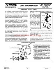
10ACC - Heating and Air Parts
10ACC - Heating and Air Parts
10ACC - Heating and Air Parts

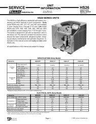
Create successful ePaper yourself
Turn your PDF publications into a flip-book with our unique Google optimized e-Paper software.
Service Literature<strong>10ACC</strong> SERIES UNITS<strong>10ACC</strong>Corp. 0201-L1The <strong>10ACC</strong> is a residential split-system condensingunit available in sizes ranging from 1-1/2 to 5 tons. Condensingcoil size, circuiting <strong>and</strong> air volume result in aminimum SEER rating of 10.0. The series is designedfor use with an expansion valve or RFCIV system in theindoor unit.<strong>10ACC</strong> 1-1/2 to 3 ton units are equipped with reciprocatingcompressors. All compressors are hermetically sealed forlong service life. The compressor is installed in the unit on resilientrubber mounts to assure quiet, vibration-free operation.A built-in protection device assures protection from excessivecurrent <strong>and</strong> temperatures.<strong>10ACC</strong> 3-1/2 to 5 ton units are equipped with scroll compressors.The scroll operates like a st<strong>and</strong>ard compressor butit is unique in the way it compresses refrigerant.This manual is divided into sections which discuss themajor components, refrigerant system, charging procedure,maintenance <strong>and</strong> operation sequence.All specifications in this manual are subject to change.WARNINGRefrigerant can be harmful if it is inhaled. Refrigerantmust be used <strong>and</strong> recovered responsibly.Failure to follow this warning may result in personalinjury or death.WARNINGElectric shock hazard. Can cause injuryor death. Before attempting to performany service or maintenance, turn theelectrical power to unit OFF at disconnectswitch(es). Unit may have multiplepower supplies.IMPORTANTImproper installation, adjustment, alteration, serviceor maintenance can cause property damage,personal injury or loss of life. Installation <strong>and</strong> servicemust be performed by a qualified installer orservice agency.Page 1ã 2002 Lennox Industries Inc.Litho U.S.A.
ELECTRICAL DATAGeneralDataModel No.<strong>10ACC</strong>-018-230<strong>10ACC</strong>-024-230<strong>10ACC</strong>-030-230<strong>10ACC</strong>-036-230<strong>10ACC</strong>-042-230<strong>10ACC</strong>-048-230<strong>10ACC</strong>-060-230Line voltage data - 60hz208/230v-1ph 208/230v-1ph 208/230v-1ph 208/230v-1ph 208/230v-1ph 208/230v-1ph 208/230v-1phRec. max fuse size (amps) 20 25 30 35 40 50 60¡Minimum circuit ampacity 11.6 14.3 17.3 20.4 23 31.2 35.5Compressor Rated load amps 8.6 10.8 12.9 16.2 17.9 21.8 25CondenserFan MotorLocked rotor amps 48.3 60 69.4 96 103 131 170Power factor 0.97 0.96 0.92 0.90 0.84 0.80 0.90Full load amps 0.8 0.8 1.1 1.7 1.9 1.9 0.9Locked rotor amps 1.2 1.2 1.9 3.1 4.1 4.1 4.1¡Refer to National or Canadian Electrical Code manual to determine wire, fuse <strong>and</strong> disconnect size requirements.NOTE — Extremes of operating range are plus 10% <strong>and</strong> minus 5% of line voltage.SPECIFICATIONSGeneralModel No. <strong>10ACC</strong>-018 <strong>10ACC</strong>-024 <strong>10ACC</strong>-030 <strong>10ACC</strong>-036 <strong>10ACC</strong>-042 <strong>10ACC</strong>-048 <strong>10ACC</strong>-060Data Nominal Tonnage (kW) 1.5 (5.3) 2 (7.0) 2.5 (8.8) 3 (10.6) 3.5 (12.3) 4 (14.1) 5 (17.6)ConnectionsLiquid line (o.d.) - in. (mm) ©3/8 (9.5) ©3/8 (9.5) 3/8 (9.5) 3/8 (9.5) 3/8 (9.5) 3/8 (9.5) 3/8 (9.5)(sweat) Suction line (o.d.) - in. (mm) 5/8 (15.9) 5/8 (15.9) 3/4 (19.1) 3/4 (19.1) 7/8 (22.2) 7/8 (22.2) 1-1/8 (28.6)Refrigerant *HCFC-22 charge furnished 4 lbs. 13 oz.(2.18 kg)4 lbs. 13 oz.(2.18 kg)4 lbs. 1 oz.(1.8 kg)4 lbs. 13 oz.(2.18 kg)5 lbs. 4 oz.(2.38 kg)6 lbs. 3 oz.(2.81 kg)8 lbs. 5 oz.(3.77 kg)Condenser Net face area - sq. ft. (m2) Outer Coil 9.24 (0.86) 9.24 (0.86) 10.46 (0.97) 11.41 (1.06) 13.31 (1.24) 15.11 (1.40) 20.83 (1.94)Coil Inner Coil - - - - - - - - - - - - - - - 5.4 (0.50) - - -Tube diameter - in. (mm) 5/16 (7.9) 5/16 (7.9) 5/16 (7.9) 5/16 (7.9) 5/16 (7.9) 5/16 (7.9) 5/16 (7.9)No. of rows 1 1 1 1 1 1.37 1Fins per inch (m) 22 (866) 22 (866) 18 (709) 22 (866) 22 (866) 22 (866) 22 (866)CondenserDiameter - in. (mm) 16 (406) 16 (406) 18 (457) 18 (457) 18 (457) 18 (457) 22 (559)Fan No. of blades 3 3 3 3 4 4 4Motor hp (W) 1/10 (75) 1/10 (75) 1/6 (124) 1/4 (187) 1/3 (249) 1/3 (249) 1/3 (249)Cfm (L/s) 1730 (815) 1730 (815) 2170 (1025) 2510 (1185) 2800 (1320) 2950 (1390) 3900 (1840)Rpm 1070 1070 1100 1103 1116 1100 1100Watts 184 184 254 266 299 310 367Shipping weight (1 package) lbs. (kg) 107 (49) 107 (49) 136 (62) 140 (64) 140 (64) 196 (89) 199 (90)OPTIONAL ACCESSORIES - MUST BE ORDERED EXTRACrankcase Heater 68887 68887 68887 68887 90P12 90P12 90P12Hail Guards 17L71 17L71 17L71 17L73 17L73 17L73 17L73Low Ambient Kit (for Expansion Valve systems only) 24H77 24H77 24H77 24H77 24H77 24H77 24H77MountingModel No.MB2-S (69J06)BaseNet Weight 6 lbs. (3 kg)Dimensions - in. (mm) 22-1/4x22-1/4x3 (565 x 565x76)Timed-Off ControlLB-61378A (47J35)Unit St<strong>and</strong>-Off Kit 94J45 94J45 94J45 94J45 94J45 94J45 94J45Unit Hard-Start Kit - 64J09 66K92 64J09 81J69 81J69 81J69Compressor Monitor (Canada only)T6-1469 (45F08)*Refrigerant charge sufficient for 20 ft. (6.0 m) length of refrigerant lines.©3/8 in. x 5/16 in. (9.5 mm x 7.9 mm) reducer bushing (not furnished) is required for liquid line connection.Page 2
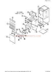
I - GENERALDANGERMake sure all power is disconnected beforebeginning electrical service procedures.STARTCAPACITOR (C7)(option only)<strong>10ACC</strong> UNIT CONTROL BOXRECIPROCATING COMPRESSORDUAL CAPACITOR(C12)<strong>10ACC</strong> condensing units are available in 1 -1/2, 2, 2 -1/2, 3, 3-1/2, 4 <strong>and</strong> 5 ton capacities.All major components (indoor blower <strong>and</strong> coil) must bematched according to Lennox recommendations for the compressorto be covered under warranty. Refer to the EngineeringH<strong>and</strong>book for approved system matchups. A misappliedsystem will cause erratic operation <strong>and</strong> can result in earlycompressor failure.II - UNIT COMPONENTSCOMPRESSORCONTACTOR(K1)GROUNDINGLUGPOTENTIALRELAY (K31)(option only)Unit components are illustrated in figure 1.<strong>10ACC</strong> UNIT COMPONENTSOUTDOORFAN/MOTORCONTROLBOXFIGURE 2<strong>10ACC</strong> UNIT CONTROL BOXScroll CompressorDUAL CAPACITOR(C12)DISCHARGELINESUCTION LINESERVICE VALVECOMPRESSORCONTACTOR(K1)GROUNDINGLUGCOMPRESSORLIQUID LINESERVICE VALVESUCTION LINEFIGURE 1FIGURE 3Page 3
B - Compressor<strong>10ACC</strong>-042, -048 <strong>and</strong> -060 units are equipped with ascroll compressor. For compressor specifications see“ELECTRICAL DATA” section in this manual or the compressornameplate.SCROLL COMPRESSORDISCHARGEPRESSURECROSS-SECTION OF SCROLLSDISCHARGESTATIONARY SCROLLSUCTIONDISCHARGESUCTIONORBITING SCROLLTIPS SEALED BYDISCHARGE PRESSUREFIGURE 6FIGURE 41 - Scroll CompressorThe scroll compressor design is simple, efficient <strong>and</strong> requiresfew moving parts. A cutaway diagram of the scrollcompressor is shown in figure 4.The scrolls are located inthe top of the compressor can <strong>and</strong> the motor is located justbelow. The oil level is immediately below the motor.The scroll is a simple compression concept centeredaround the unique spiral shape of the scroll <strong>and</strong> its inherentproperties. Figure 5 shows the basic scroll form. Two identicalscrolls are mated together forming concentric spiralshapes (figure 6 ). One scroll remains stationary, while theother is allowed to “orbit” (figure 7). Note that the orbitingscroll does not rotate or turn but merely “orbits” the stationaryscroll.SCROLL FORMFIGURE 5The counterclockwise orbiting scroll draws gas into the outercrescent shaped gas pocket created by the two scrolls(figure 7 - 1). The centrifugal action of the orbiting scrollseals off the flanks of the scrolls (figure 7 - 2). As the orbitingmotion continues, the gas is forced toward the center of thescroll <strong>and</strong> the gas pocket becomes compressed (figure 7 -3). When the compressed gas reaches the center, it is dischargedvertically into a chamber <strong>and</strong> discharge port in thetop of the compressor (figure 6). The discharge pressureforcing down on the top scroll helps seal off the upper <strong>and</strong>lower edges (tips) of the scrolls (figure 6 ). During a singleorbit, several pockets of gas are compressed simultaneouslyproviding smooth continuous compression.The scroll compressor is tolerant to the effects of liquid return.If liquid enters the scrolls, the orbiting scroll is allowedto separate from the stationary scroll. The liquid is workedtoward the center of the scroll <strong>and</strong> is discharged. If thecompressor is replaced, conventional Lennox cleanuppractices must be used.Due to its efficiency, the scroll compressor is capable ofdrawing a much deeper vacuum than reciprocating compressors.Deep vacuum operation can cause internal fusitearcing resulting in damaged internal parts <strong>and</strong> will resultin compressor failure. Never use a scroll compressorfor evacuating or “pumping-down” the system. This type ofdamage can be detected <strong>and</strong> will result in denial of warrantyclaims.NOTE - During operation, the head of a scroll compressormay be hot since it is in constant contact with dischargegas.Page 5
SUCTIONPOCKET1SUCTIONSTATIONARY SCROLLSUCTIONHOW A SCROLL WORKSMOVEMENT OF ORBITORBITINGSCROLLSUCTION2FLANKSSEALED BYCENTRIFUGALFORCESUCTIONINTERMEDIATEPRESSUREGASCRESCENTSHAPED GASPOCKET3 4HIGHPRESSUREGASC - Condenser Fan MotorAll units use single-phase PSC fan motors which require a runcapacitor. In all units, the condenser fan is controlled by thecompressor contactor.ELECTRICAL DATA tables in this manual show specificationsfor condenser fans used in <strong>10ACC</strong>s.Access to the condenser fan motor on all units is gainedby removing the seven screws securing the fan assembly.See figure 8. The condenser fan motor is removedfrom the fan guard by removing the four nuts found onthe top panel. See figure 9 if condenser fan motor replacementis necessary.FIGURE 7Remove (7) screwsRemove (4) nutsFANDISCHARGEPOCKETCONDENSER FAN MOTORAND COMPRESSOR ACCESSMOTORRACEWAYREMOVE (7) SCREWSSECURING FAN GUARD.REMOVE FAN GUARD/FANASSEMBLY.FIGURE 8FAN GUARDWIRINGALIGN FAN HUB FLUSH WITH END OF SHAFTFIGURE 9Page 6
III - REFRIGERANT SYSTEMA - PlumbingField refrigerant piping consists of liquid <strong>and</strong> suction linesfrom the condensing unit (sweat connections) to the indoorevaporator coil (flare or sweat connections). Use LennoxL10 (flare) or L15 (sweat, non-flare) series line sets asshown in table 1 or use field-fabricated refrigerant lines.Separate discharge <strong>and</strong> suction service ports are providedoutside the unit for connection of gauge manifoldduring charging procedure.TABLE 1Model<strong>10ACC</strong>-018<strong>10ACC</strong>-024<strong>10ACC</strong>-030<strong>10ACC</strong>-036<strong>10ACC</strong>-042<strong>10ACC</strong>-048<strong>10ACC</strong>-060LiquidLine5/16 in*(8 mm)3/8 in(10 mm)3/8 in(10 mm)3/8 in(10 mm)SuctionLine5/8 in(16 mm)3/4 in.(19 mm)7/8 in.(22 mm)1-1/8 in.(29 mm)L15Line SetsL15-2120 ft.- 50 ft.(6m - 15m)L15-4120 ft.- 50 ft.(6m - 15m)L15-6530 ft.- 50 ft.(9m - 15m)FieldFabricated*Field fabricate. See Corp. 9351-L9 Refrigerant Piping NabualB - Service ValvesThe liquid <strong>and</strong> suction line service valves (figures 10 <strong>and</strong> 11)<strong>and</strong> gauge ports are accessible from outside the unit.The valve is equipped with a service port. The service portsare used for leak testing, evacuating, charging <strong>and</strong> checkingcharge. A schrader valve is factory installed. A service port capis supplied to protect the schrader valve from contamination<strong>and</strong> serve as the primary leak seal.NOTE-Always keep valve stem caps clean.To Access Schrader Port:1 - Remove service port cap with an adjustable wrench.2 - Connect gauge to the service port.3 - When testing is completed, replace service port cap.Tighten finger tight, then an additional 1/6 turn.To Open Liquid or Suction Line Service Valve:1 - Remove stem cap with an adjustable wrench.2 - Using service wrench <strong>and</strong> hex head extension (3/16 forliquid line <strong>and</strong> 5/16 for suction line) back the stem outcounterclockwise until the valve stem just touches theretaining ring.3 - Replace stem cap tighten firmly. Tighten finger tight, thentighten an additional 1/6 turn.DANGERDo not attempt to backseat this valve. Attempts tobackseat this valve will cause snap ring to explodefrom valve body under pressure of refrigerant.Personal injury <strong>and</strong> unit damage will result.To Close Liquid or Suction Line Service Valve:1 - Remove stem cap with an adjustable wrench.2 - Using service wrench <strong>and</strong> hex head extension (3/16 forliquid line <strong>and</strong> 5/16 for suction line), turn stem clockwiseto seat the valve. Tighten firmly.3 - Replace stem cap. Tighten finger tight, then tighten anadditional 1/6 turn.LIQUID LINE SERVICE VALVE (VALVE OPEN)SER-VICEPORTOUTLET (TOCOMPRESSOR)SERVICEPORTCAPINSERT HEXWRENCH HERESCHRADERVALVESERVICEPORTSERVICEPORT CAPSCHRADER VALVE OPENTO LINE SET WHEN VALVEIS CLOSED (FRONTSEATED)FIGURE 10STEM CAPINLET (TOINDOOR COIL)LIQUID LINE SERVICE VALVE (VALVE CLOSED)RETAINING RING STEM CAPOUTLET (TOCOMPRESSOR)INSERT HEXWRENCH HEREINLET(TO INDOOR COIL)(VALVE FRONTSEATED)Page 7
SUCTION LINE SERVICE VALVE (VALVE OPEN)INSERT HEXWRENCH HEREINLET (TOINDOOR COIL)STEM CAPSUCTION LINE (BALL TYPE) SERVICE VALVE(VALVE OPEN)USE ADJUSTABLE WRENCHROTATE STEM CLOCKWISE 90_ TO CLOSEROTATE STEM COUNTER-CLOCKWISE 90_ TO OPENINLET(FROM INDOOR COIL)STEM CAPSCHRADERVALVESERVICE PORTCAPSERVICEPORTSERVICE PORTCAPSERVICE PORTRETAINING RINGSCHRADER VALVE OPENTO LINE SET WHEN VALVE ISCLOSED (FRONT SEATED)FIGURE 11OUTLET (TOCOMPRESSOR)SUCTION LINE SERVICE VALVE (VALVE CLOSED)INLET (TOINDOOR COIL)STEM CAPINSERT HEXWRENCH HERE(VALVE FRONTSEATED)OUTLET (TOCOMPRESSOR)Suction Line (Ball Type) Service Valve(5 Ton Only)A ball-type full service valve is used on <strong>10ACC</strong> 5 tonunits. These suction line service valves function thesame way, differences are in construction. Valves arenot rebuildable. If a valve has failed it must be replaced. A ballvalve is illustrated in figure 12.The ball valve is equipped with a service port. A schradervalve is factory installed. A service port cap is supplied to protectthe schrader valve from contamination <strong>and</strong> assure aleak free seal.SERVICEPORTCAPIV - CHARGINGSTEMSERVICE PORTSCHRADER COREFIGURE 12A - Pumping Down SystemCAUTIONBALL(SHOWN OPEN)OUTLET(TOCOMPRESSOR)Deep vacuum operation (operating compressor at 0psig or lower) can cause internal fusite arcingresulting in a damaged or failed compressor. Thistype of damage will result in denial of warranty claim.The system may be pumped down when leak checking theline set <strong>and</strong> indoor coil or making repairs to the line set orindoor coil.1- Attach gauge manifold.2- Front seat (close) liquid line valve.3- Start outdoor unit.4- Monitor suction gauge. Stop unit when 0 psig is reached.5- Front seat (close) suction line valve.B - Leak Testing (To Be DoneBefore Evacuating)1- Attach gauge manifold <strong>and</strong> connect a drum of dry nitrogento center port of gauge manifold.2- Open high pressure valve on gauge manifold <strong>and</strong>pressurize line set <strong>and</strong> indoor coil to 150 psig (1034kPa).3- Check lines <strong>and</strong> connections for leaks.NOTE-If electronic leak or Halide detector is used, add asmall amount of R-22 (3 to 5 psig [20kPa to 34kPa]) thenpressurize with nitrogen to 150 psig.4- Release nitrogen pressure from the system, correct anyleaks <strong>and</strong> recheck.Page 8
CAUTIONWhen using dry nitrogen, a pressure reducing regulatormust be used to prevent excessive pressurein gauge manifold, connecting hoses, <strong>and</strong>within the system. Regulator setting must not exceed150 psig (1034 kpa). Failure to use a regulatorcan cause equipment failure resulting in injury.C - Evacuating the System1- Attach gauge manifold. Connect vacuum pump (with vacuumgauge) to center port of gauge manifold. With bothmanifold service valves open, start pump <strong>and</strong> evacuateindoor coil <strong>and</strong> refrigerant lines.IMPORTANTA temperature vacuum gauge, mercury vacuum(U-tube), or thermocouple gauge should be used.The usual Bourdon tube gauges are not accurateenough in the vacuum range.IMPORTANTThe compressor should never be used to evacuatea refrigeration or air conditioning system.2- Evacuate the system to 29 inches (737mm) vacuum.During the early stages of evacuation, it is desirable tostop the vacuum pump at least once to determine if thereis a rapid loss of vacuum. A rapid loss of vacuum wouldindicate a leak in the system <strong>and</strong> a repeat of the leaktesting section would be necessary.3- After system has been evacuated to 29 inches(737mm), close gauge manifold valves to center port,stop vacuum pump <strong>and</strong> disconnect from gauge manifold.Attach an upright nitrogen drum to center port ofgauge manifold <strong>and</strong> open drum valve slightly to purgeline at manifold. Break vacuum in system with nitrogenpressure by opening manifold high pressurevalve. Close manifold high pressure valve to centerport.4- Close nitrogen drum valve <strong>and</strong> disconnect fromgauge manifold center port. Release nitrogen pressurefrom system.5- Connect vacuum pump to gauge manifold centerport. Evacuate system through manifold servicevalves until vacuum in system does not rise above.5mm of mercury absolute pressure or 500 micronswithin a 20-minute period after stopping vacuum pump.6- After evacuation is complete, close manifold center port,<strong>and</strong> connect refrigerant drum. Pressurize systemslightly with refrigerant to break vacuum.D - ChargingUnits are factory charged with the amount of HCFC-22 refrigerantindicated on the unit nameplate. This charge isbased on a matching indoor coil <strong>and</strong> outdoor coil with a 20ft. (6.1 m) line set. For varying lengths of line set, refer totable 2 for refrigerant charge adjustment. A blank space isprovided on the nameplate to list the actual field charge.Liquid LineSet DiameterTABLE 2Oz. per 5 ft. (g per 1.5 m) adjustfrom 20 ft. (6.1 m) line set*5/16 in. (8 mm) 2 ounce per 5 ft. (57g per 1.5 m)3/8 in. (10 mm) 3 ounce per 5 ft. (85g per 1.5 m)*If line length is greater than 20 ft. (6.1 m), add this amount.If line length is less than 20 ft. (6.1 m), subtract this amount.The condensing unit should be charged during warmweather. However, applications arise in which chargingmust occur in the colder months. The method of charging isdetermined by the unit’s refrigerant metering device <strong>and</strong>the outdoor ambient temperature.Measure the liquid line temperature <strong>and</strong> the outdoor ambienttemperature as outlined below:1. -Connect the manifold gauge set to the service valves:low pressure gauge to suction valve service port; highpressure gauge to liquid valve service port. Connectthe center manifold hose to an upright cylinder ofHCFC-22. Close manifold gauge set valves.2. -Set the room thermostat to call for heat. This will createthe necessary load for properly charging the system inthe cooling cycle.3. -Use a digital thermometer to record the outdoor ambienttemperature.4. -When the heating dem<strong>and</strong> has been satisfied, switchthe thermostat to cooling mode with a set point of 68_F(20_C). When pressures have stabilized, use a digitalthermometer to record the liquid line temperature.5. -The outdoor temperature will determine which chargingmethod to use. Proceed with the appropriatecharging procedure.Page 9
Weighing in the Charge Fixed Orifice orTXV Systems – Outdoor Temp < 60_F (16_C)If the system is void of refrigerant, or if the outdoor ambienttemperature is cool, the refrigerant charge should beweighed into the unit according to the total amount shownon the unit nameplate. This may be done after any leakshave been repaired. If weighing facilities are not availableor if unit is being charged during warm weather, follow oneof the other procedures outlined below.1 - Recover the refrigerant from the unit.2 - Conduct a leak check, then evacuate as previouslyoutlined.3 - Weigh in the factory charge according to the amountrecorded on the outdoor unit nameplate.Charging Using the Subcooling MethodFixed Orifice Systems – Outdoor Temp.> 65_F (18_C)If you charge a fixed orifice system when the outdoor ambientis 65_F (18_C) or above, use the subcooling method tocharge the unit.1 - With the manifold gauge hose still on the liquid serviceport <strong>and</strong> the unit operating stably, use a digital thermometerto record the liquid line temperature.2 - At the same time, record the liquid line pressure reading.3 - Use a temperature/pressure chart for HCFC-22 to determinethe saturation temperature for the liquid linepressure reading.4 - Subtract the liquid line temperature from the saturationtemperature (according to the chart) to determine subcooling.(Saturation temperature - Liquid line temperature= Subcooling)5 - Compare the subcooling value with those in table 3. Ifsubcooling is greater than shown, some refrigerantmust be recovered. If subcooling is less than shown,some refrigerant must be added.Table 3<strong>10ACC</strong> Subcooling Values(Fixed Orifice Systems Only)OUTDOOR LIQUID SUBCOOLING [+ 1_F (.6_C)]TEMP._F (_C) 18 24 30 36 42 48 6065(18)70(21)75(24)80(27)85(29)90(32)95(35)100(38)105(41)110(43)115(45)13(7)13(7)13(7)12(6.7)12(6.7)11(6)10(5.6)9(5)8(4.5)7(4)7(4)14(8)14(8)13(7)13(7)12(6.7)12(6.7)11(6)9(5)8(4.5)7(4)6(3.3)14(8)14(8)13(7)13(7)13(7.8)12(6.7)11(6)10(5.6)9(5)7(4)6(3.3)17(9.5)17(9.5)16(9)15(8.3)14(8)14(8)12(6.7)11(6)10(5.6)9(5)8(4.5)17(9.5)17(9.5)16(9)15(8.3)14(8)14(8)14(8)13(7)12(6.7)11(6)11(6)15(8.3)14(8)13(7)13(7)12(6.7)12(6.7)12(6.7)11(6)10(5.6)9(5)8(4.5)14(8)15(8.3)15(8.3)14(8)14(8)13(7)13(7)12(6.7)12(6.7)11(6)10(5.6)Charging Using the Approach MethodTXV Systems -- Outdoor Temp. > 60_F (16_C)When an expansion valve system is being charged whenthe outdoor ambient temperature is 60_F (16_C) or above,it is best to charge the unit using the approach method.Subtract the outdoor ambient temperature from the liquidline temperature to determine the Approach temperature.(Liquid Line _F (_C) - Outdoor Ambient _F (_C) = ApproachTemperature.) The resulting difference (Approachtemperature) should agree with the values given intable 4. If not, add refrigerant to lower the approach temperatureor recover refrigerant from the system to increasethe approach temperature.Table 4Approach MethodModel No.Approach TemperatureLiquid Line - Outdoor Ambient _F (_C)<strong>10ACC</strong>-018 7 (4)<strong>10ACC</strong>-024 9 (5)<strong>10ACC</strong>-030 12 (6.7)<strong>10ACC</strong>-036 11 (6)<strong>10ACC</strong>-042 13 (7)<strong>10ACC</strong>-048 8 (4.5)<strong>10ACC</strong>-060 13 (7)NOTE - For best results, use the same digital thermometer to check bothoutdoor ambient <strong>and</strong> liquid temperatures.Page 10
Unit /MeteringDevice<strong>10ACC</strong> /fixed orifice<strong>10ACC</strong> /TXVOut. CoilEntering<strong>Air</strong> Temp.°F (°C)Table 5Normal Operating Pressures In psig (liquid <strong>and</strong> suction +/- 2 psig)*-018 -024 -030 -036 -042 -048 -060LIQ. SUC. LIQ. SUC. LIQ. SUC. LIQ. SUC. LIQ. SUC. LIQ. SUC. LIQ. SUC.65 (18.3) 154 62 165 68 170 76 168 67 178 67 163 68 189 7275 (23.9) 181 68 190 73 199 78 195 71 202 70 190 71 203 7485 (29.4) 210 73 219 77 231 80 224 75 235 71 220 74 233 7795 (35.0) 237 77 250 80 264 81 255 78 270 74 251 77 265 79105 (40.6) 272 82 282 83 300 82 289 82 308 78 288 79 301 82110 (43) 288 83 301 84 321 83 305 83 326 79 307 80 319 83115 (45) 306 85 317 85 339 84 324 84 347 80 325 82 339 8465 (18.3) 156 68 162 73 170 76 162 70 173 73 159 71 170 7475 (23.9) 180 70 189 74 199 78 187 74 201 74 188 72 201 7685 (29.4) 208 72 218 75 231 80 219 75 234 74 220 73 234 7795 (35.0) 237 73 249 77 264 81 253 77 269 75 251 76 270 79105 (40.6) 268 75 285 78 300 82 291 79 307 76 290 77 309 79110 (43) 284 76 301 79 321 83 310 80 326 77 309 78 331 80115 (45) 302 77 321 81 339 84 329 81 346 78 328 79 351 81*These are typical pressures only. Indoor evaporator match up, indoor air quality, <strong>and</strong> evaporator load will cause the pressures to vary.IMPORTANTUse table 5 to perform maintenance checks. Table 5is not a procedure for charging the system. Minorvariations in these pressures may be due to differencesin installations. Significant deviations couldmean that the system is not properly charged or thata problem exists with some component in the system.See table 5.E - MaintenanceWARNINGElectric shock hazard. Can cause injuryor death. Before attempting to performany service or maintenance, turnthe electrical power to unit OFF at disconnectswitch(es). Unit may havemultiple power supplies.Maintenance <strong>and</strong> service must be performed by a qualifiedinstaller or service agency. At the beginning of each coolingseason, the system should be checked as follows:1 - Clean <strong>and</strong> inspect the condenser coil. The coil may beflushed with a water hose. Make sure power is off beforecleaning.2 - Visually inspect connecting lines <strong>and</strong> coils for evidenceof oil leaks.3 - Check wiring for loose connections.4 - Check for correct voltage at unit (unit operating).5 - Check the compressor <strong>and</strong> condenser fan motor ampdraw.NOTE - If the owner complains of insufficient cooling,the unit should be gauged <strong>and</strong> the refrigerant chargeshould be checked. Refer to the charging section inthis instruction.Evaporator Coil1 - Clean coil, if necessary.2 - Check connecting lines <strong>and</strong> coils for evidence of oilleaks.3 - Check the condensate pan line <strong>and</strong> clean it if necessary.Indoor Unit1 - Clean or change filters.2 - Adjust blower speed for cooling. The pressure drop overthe coil should be measured to determine the correctblower CFM. Refer to the unit information service manualfor pressure drop tables <strong>and</strong> procedure.3 - Belt Drive Blowers - Check belt for wear <strong>and</strong> propertension.4 - Check all wiring for loose connections5 - Check for correct voltage at unit (blower operating).6 - Check amp-draw on blower motor.Page 11
V - WIRING DIAGRAMS AND SEQUENCE OF OPERATION<strong>10ACC</strong> OPERATING SEQUENCE1526734NOTE- The thermostat used may be electromechanical or electronic.NOTE- Transformer in indoor unit supplies power (24 VAC) to the thermostat <strong>and</strong> outdoor unit controls.COOLING:1 - Cooling dem<strong>and</strong> initiates at Y1 in the thermostat.2 - 24VAC energizes compressor contactor K1.3 - K1-1 N.O. closes, energizing compressor (B1) <strong>and</strong> outdoor fan motor (B4).4 - Compressor (B1) <strong>and</strong> outdoor fan motor (B4) begin immediate operation.END OF COOLING DEMAND:5 - Cooling dem<strong>and</strong> is satisfied. Terminal Y1 is de-energized.6 - Compressor contactor K1 is de-energized.7 - K1-1 opens <strong>and</strong> compressor (B1) <strong>and</strong> outdoor fan motor (B4) are de-energized <strong>and</strong> stop immediately.Page 12