g20 service manual - Heating and Air Parts
g20 service manual - Heating and Air Parts
g20 service manual - Heating and Air Parts

Create successful ePaper yourself
Turn your PDF publications into a flip-book with our unique Google optimized e-Paper software.
Corp. 9418–L9<br />
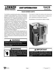
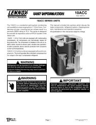
Service Literature<br />
Revised 04–2003<br />
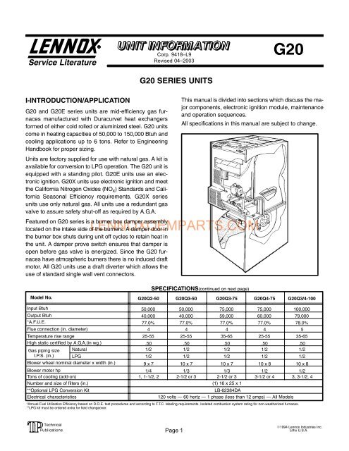
G20<br />
I−INTRODUCTION/APPLICATION<br />
G20 <strong>and</strong> G20E series units are mid−efficiency gas fur<br />
naces manufactured with Duracurvet heat exchangers<br />
formed of either cold rolled or aluminized steel. G20 units<br />
come in heating capacities of 50,000 to 150,000 Btuh <strong>and</strong><br />
cooling applications up to 6 tons. Refer to Engineering<br />
H<strong>and</strong>book for proper sizing.<br />
Units are factory supplied for use with natural gas. A kit is<br />
available for conversion to LPG operation. The G20 unit is<br />
equipped with a st<strong>and</strong>ing pilot. G20E units use an elec<br />
tronic ignition. G20X units use electronic ignition <strong>and</strong> meet<br />
the California Nitrogen Oxides (NO x ) St<strong>and</strong>ards <strong>and</strong> Cali<br />
fornia Seasonal Efficiency requirements. G20X series<br />
units use only natural gas. All units use a redundant gas<br />
valve to assure safety shut−off as required by A.G.A.<br />
Featured on G20 series is a burner box damper assembly<br />
located on the intake side of the burners. A damper door in<br />
the burner box shuts during unit off cycles to retain heat in<br />
the unit. A damper prove switch ensures that damper is<br />
open before gas valve is energized. Since the G20 fur<br />
naces have atmospheric burners there is no induced draft<br />
motor. All G20 units use a draft diverter which allows the<br />
use of st<strong>and</strong>ard single wall vent connectors.<br />
G20 SERIES UNITS<br />
This <strong>manual</strong> is divided into sections which discuss the ma<br />
jor components, electronic ignition module, maintenance<br />
<strong>and</strong> operation sequences.<br />
All specifications in this <strong>manual</strong> are subject to change.<br />
LENNOXOEMPARTS.COM<br />
Model No.<br />
SPECIFICATIONS(continued on next page)<br />
G20Q2−50 G20Q3−50 G20Q3−75 G20Q4−75 G20Q3/4−100<br />
Input Btuh<br />
Output Btuh<br />
*A.F.U.E.<br />
Flue connection (in. diameter)<br />
Temperature rise range<br />
High static certified by A.G.A.(in wg.)<br />
Gas piping size Natural<br />
I.P.S. (in.) LPG<br />
Blower wheel nominal diameter x width (in.)<br />
Blower motor hp<br />
Tons of cooling (add−on)<br />
Number <strong>and</strong> size of filters (in.)<br />
**Optional LPG Conversion Kit<br />
Electrical characteristics<br />
50,000<br />
40,000<br />
77.0%<br />
4<br />
25−55<br />
.50<br />
1/2<br />
1/2<br />
9 x 7<br />
1/4<br />
1, 1−1/2, 2<br />
50,000<br />
40,000<br />
77.0%<br />
4<br />
25−55<br />
.50<br />
1/2<br />
1/2<br />
10 x 7<br />
1/3<br />
2−1/2 or 3<br />
75,000<br />
59,000<br />
77.0%<br />
4<br />
35−65<br />
.50<br />
1/2<br />
1/2<br />
10 x 7<br />
1/3<br />
2−1/2 or 3<br />
75,000<br />
60,000<br />
77.0%<br />
4<br />
25−55<br />
.50<br />
1/2<br />
1/2<br />
10 x 8<br />
1/2<br />
3−1/2 or 4<br />
100,000<br />
79,000<br />
78.0%<br />
5<br />
35−65<br />
.50<br />
1/2<br />
1/2<br />
10 x 8<br />
1/2<br />
3, 3−1/2, 4<br />
(1) 16 x 25 x 1<br />
LB−62384DA<br />
120 volts 60 hertz 1 phase (less than 12 amps) All Models<br />
*Annual Fuel Utilization Efficiency based on D.O.E. test procedures <strong>and</strong> according to F.T.C. labeling requirements. Isolated combustion system rating for non−weatherized furnaces.<br />
**LPG kit must be ordered extra for field changeover.<br />
Page 1<br />
1994 Lennox Industries Inc.<br />
Litho U.S.A.
SPECIFICATIONS (continued from previous page)<br />
Model No.<br />
Input Btuh<br />
Output Btuh<br />
*A.F.U.E.<br />
Flue connection (in. diameter)<br />
Temperature rise range<br />
High static certified by A.G.A.(in wg.)<br />
Gas piping size<br />
I.P.S. (in.)<br />
Natural<br />
LPG<br />
Blower wheel nominal diameter x width (in.)<br />
Blower motor hp<br />
Tons of cooling (add−on)<br />
Number <strong>and</strong> size of filters (in.)<br />
**Optional LPG Conversion Kit<br />
Electrical characteristics<br />
G20Q5/6−100 G20Q3−125 G20Q4/5−125 G20Q5/6−150<br />
100,000<br />
79,000<br />
78.0%<br />
5<br />
25−55<br />
.75<br />
1/2<br />
1/2<br />
12 x 12<br />
3/4<br />
5 or 6<br />
125,000<br />
100,000<br />
77.0%<br />
125,000<br />
99,000<br />
78.0%<br />
150,000<br />
115,000<br />
78.0%<br />
6 6 6<br />
70−100 35−65 40−70<br />
.50 .50 .50<br />
1/2<br />
1/2<br />
1/2<br />
1/2<br />
1/2<br />
1/2<br />
10 x 8 12 x 12 12 x 12<br />
1/3 3/4 3/4<br />
2−1/2 or 3 4 or 5<br />
5 or 6<br />
(1) 20 x 25 x 1<br />
LB−62384DA<br />
120 volts 60 hertz 1 phase (less than 12 amps) All Models<br />
Model No.<br />
Input Btuh<br />
Output Btuh<br />
*A.F.U.E.<br />
Output BtuhX" models<br />
*A.F.U.E.X" models<br />
California Seasonal EfficiencyX" models<br />
Flue connection (in. diameter)<br />
Temperature rise range<br />
High static certified by A.G.A.(in wg.)<br />
Gas piping size<br />
I.P.S. (in.)<br />
Blower wheel nominal diameter x width (in.)<br />
Blower motor hp<br />
Tons of cooling (add−on)<br />
Number <strong>and</strong> size of filters (in.)<br />
**Optional LPG Conversion Kit<br />
Electrical characteristics<br />
G20Q2E−50 G20Q3E−50 G20Q3E−75 G20Q4E−75 G20Q3/4E−100<br />
♦G20Q2X−50 ♦G20Q3X−50 ♦G20Q3X−75 ♦G20Q4X−75 ♦G20Q3/4X−100<br />
50,000 50,000<br />
75,000<br />
75,000<br />
100,000<br />
39,000 39,000<br />
59,000<br />
60,000<br />
78,000<br />
80.0%<br />
80.0%<br />
80.0% 80.0%<br />
80.0%<br />
39,000 39,000<br />
59,000<br />
60,000<br />
78,000<br />
80.0%<br />
80.0%<br />
80.0%<br />
80.0%<br />
80.0%<br />
75.1%<br />
74.2%<br />
76.0%<br />
75.3%<br />
76.0%<br />
4<br />
4<br />
4 4 5<br />
25−55<br />
25−55<br />
35−65<br />
25−55<br />
35−65<br />
.50<br />
.50<br />
.50 .50 .50<br />
1/2<br />
1/2<br />
1/2<br />
1/2<br />
1/2<br />
9 x 7<br />
10 x 7<br />
10 x 7 10 x 8<br />
10 x 8<br />
1/4<br />
1/3<br />
1/3 1/2<br />
1/2<br />
1, 1−1/2, 2 2−1/2 or 3 2−1/2 or 3 3−1/2 or 4 3, 3−1/2, 4<br />
(1) 16 x 25 x 1<br />
LB−62384DB<br />
120 volts 60 hertz 1 phase (less than 12 amps) All Models<br />
Natural<br />
1/2<br />
1/2<br />
LENNOXOEMPARTS.COM<br />
LPG<br />
1/2<br />
1/2<br />
1/2<br />
Model No.<br />
G20Q5/6E−100<br />
♦G20Q5/6X−100<br />
G20Q3E−125 G20Q4/5E−125 G20Q5/6E−150<br />
♦G20Q3X−125 ♦G20Q4/5X−125 ♦G20Q5/6X−150<br />
Input Btuh<br />
Output Btuh<br />
*A.F.U.E.<br />
100,000<br />
78,000<br />
80.0%<br />
125,000<br />
95,000<br />
79.5%<br />
125,000<br />
97,000<br />
80.0%<br />
150,000<br />
116,000<br />
80.0%<br />
Output BtuhX" models<br />
78,000<br />
95,000<br />
97,000<br />
116,000<br />
*A.F.U.E.X" models<br />
80.0%<br />
79.5%<br />
80.0%<br />
80.0%<br />
California Seasonal EfficiencyX" models<br />
75.0%<br />
77.0%<br />
76.1%<br />
75.7%<br />
Flue connection (in. diameter)<br />
5<br />
6<br />
6 6<br />
Temperature rise range<br />
High static certified by A.G.A.(in wg.)<br />
25−55<br />
.75<br />
70−100<br />
.50<br />
35−65<br />
.50<br />
40−70<br />
.50<br />
Gas piping size<br />
I.P.S. (in.)<br />
Natural<br />
LPG<br />
1/2<br />
1/2<br />
1/2<br />
1/2<br />
1/2<br />
1/2<br />
1/2<br />
1/2<br />
Blower wheel nominal diameter x width (in.)<br />
12 x 12<br />
10 x 8<br />
12 x 12 12 x 12<br />
Blower motor hp<br />
Tons of cooling (add−on)<br />
3/4<br />
5 or 6<br />
1/3<br />
2−1/2 or 3<br />
3/4<br />
4 or 5<br />
3/4<br />
5 or 6<br />
Number <strong>and</strong> size of filters (in.)<br />
(1) 20 x 25 x 1<br />
*Optional LPG Conversion Kit<br />
LB−62384DB<br />
Electrical characteristics<br />
120 volts 60 hertz 1 phase (less than 12 amps) All Models<br />
*Annual Fuel Utilization Efficiency based on D.O.E. test procedures <strong>and</strong> according to F.T.C. labeling requirements. Isolated combustion system rating for non−weatherized furnaces.<br />
**LPG kit must be ordered extra for field changeover.<br />
♦Not available with LPG.<br />
Page 2
CABINET CAP<br />
TOP STRIP<br />
DRAFT<br />
HOOD<br />
PARTS IDENTIFICATION<br />
(G20E Units Shown)<br />
REAR BAFFLE<br />
UPPER ACCESS<br />
PANEL<br />
VENT SAFETY<br />
SHUT−OFF<br />
SWITCH<br />
HEAT<br />
EXCHANGER<br />
GAS<br />
MANIFOLD<br />
IGNITION<br />
CONTROL<br />
(G20E &G20X<br />
Units Only)<br />
LIMIT<br />
CONTROL<br />
CABINET<br />
ROLL−OUT<br />
SWITCH<br />
GAS VALVE<br />
BURNER BOX<br />
BURNER BOX<br />
DAMPER ASSEMBLY<br />
PILOT/ELECTRODE<br />
ASSEMBLY<br />
BURNERS<br />
BLOWER<br />
CONTROL BOX<br />
ROLL−OUT<br />
SWITCH<br />
FIGURE 1<br />
LENNOXOEMPARTS.COM<br />
DAMPER BOX PARTS ARRANGEMENT<br />
(G20 Units Shown)<br />
OBSERVATION PORT<br />
COVER<br />
PILOT PATCH<br />
PLATE<br />
G20 CONTROL BOX FRONT VIEW<br />
DAMPER<br />
DOOR<br />
DOOR<br />
INTERLOCK<br />
S51<br />
PROVE<br />
SWITCH COVER<br />
DAMPER<br />
PROVE SWITCH<br />
SPRING<br />
DAMPER<br />
DAMPER OPENING<br />
BOX<br />
BCC2−1<br />
CONTROL<br />
A15<br />
BLOWER<br />
FIGURE 3<br />
TRANSFORMER<br />
T1<br />
PATCH PLATE<br />
PILOT<br />
LIGHTING ROD<br />
(G20 UNITS ONLY)<br />
DAMPER<br />
FIGURE 2<br />
PATCH PLATE<br />
DAMPER<br />
MOTOR/GEAR<br />
II−UNIT COMPONENTS<br />
A−Control Box (Figure 3)<br />
On G20 series units the unit control box is located in the<br />
blower compartment between the burner box <strong>and</strong> the<br />
blower housing. The hinged control box can be lowered for<br />
<strong>service</strong> access by removing two securing screws, one lo<br />
cated on either side. At the top right corner of the control<br />
box is the door interlock switch (S51).<br />
Housed in the control box are the unit transformer (T1) <strong>and</strong><br />
the BCC2−1 blower control (A15).<br />
Page 3
1− Control Transformer (T1)<br />
A transformer located inside the control box provides pow<br />
er to the low voltage section of the unit. Transformers on all<br />
models are rated 30VA with a 120V primary <strong>and</strong> a 24V sec<br />
ondary.<br />
2− BCC2−1 through BCC3−2 Blower Control<br />
(A15)<br />
All G20 units utilize the BCC blower control. The BCC is a<br />
printed circuit board which controls the blower <strong>and</strong> moni<br />
tors primary limit <strong>and</strong> gas valve operation. The control has<br />
a non−adjustable, factory preset on" fan timing. Fan off"<br />
timings are adjustable. The board is divided into two sec<br />
tions, 120 <strong>and</strong> 24VAC. Line voltage comes into the board<br />
on the 120VAC side. See figure 4.<br />
CAB" <strong>and</strong> XFMR " send 120VAC to the damper motor<br />
<strong>and</strong> transformer, respectively. The active cooling <strong>and</strong><br />
heating blower speed terminals <strong>and</strong> three dummy D" ter<br />
minals are located on the 120VAC side of the BCC. Also<br />
located on the 120VAC side of the control are neutral ter<br />
minals <strong>and</strong> a terminal for accessories such as an electron<br />
ic air cleaner. The HSI" terminal is not used.<br />
24VAC comes from the transformer into terminal 24V" on<br />
the 24VAC side of the BCC. Thermostat connections <strong>and</strong><br />
safety circuit terminals are also located on the 24VAC side<br />
of the control. Fan off" timings may be adjusted by chang<br />
ing the position of a jumper across terminal pins. Thermo<br />
stat terminal strips on early model BCC boards are remov<br />
able. Late model boards have permanent thermostat<br />
strips.<br />
Blower Speed Taps<br />
Blower speed tap changes are made on the BCC<br />
blower control board at the upper right corner. See fig<br />
ure 4. Unused speed taps must be secured to the<br />
dummy D" terminals on the BCC. The active heating<br />
tap is connected to the H" terminal <strong>and</strong> the active<br />
cooling tap is connected to the A" terminal.<br />
Table 1 shows the blower motor tap colors for each<br />
speed. To change a heating speed tap, turn off power,<br />
remove existing speed tap from the H" terminal <strong>and</strong><br />
place on D" terminal. Next select new speed wire <strong>and</strong><br />
place on H" terminal of the blower control <strong>and</strong> restore<br />
power. Blower speed tap information can also be<br />
found on the G20 unit wiring diagram.<br />
TABLE 1<br />
SPEED<br />
BLOWER SPEED SELECTION<br />
Q2−50<br />
Q3−75<br />
LENNOXOEMPARTS.COM<br />
BLOWER MOTOR LEAD<br />
Q3−50, Q4−75<br />
Q3/4−100<br />
Q3−125<br />
Q5/5−100<br />
Q4/5−125<br />
Q5/6−150<br />
LOW RED RED RED<br />
MEDIUM LOW − YELLOW YELLOW<br />
MEDIUM YELLOW − BLUE<br />
MEDIUM HI − BROWN BROWN<br />
HIGH BLACK BLACK BLACK<br />
NEUTRAL<br />
TERMINALS<br />
COOLING<br />
SPEED TAP<br />
TERMINAL<br />
DUMMY<br />
TERMINALS<br />
CONTINUOUS FAN<br />
TERMINAL<br />
HEATING<br />
SPEED TAP<br />
TERMINAL<br />
ACCESSORY<br />
TERMINAL<br />
BCC3−2 SHOWN<br />
Heat Anticipator Settings<br />
Beginning with the BCC3−2 series, a 3 pin jumper has<br />
been installed on the board next to the removable 24V<br />
terminal strip to account for both programmable <strong>and</strong><br />
electromechanical thermostat usage in the field. For<br />
electromechanical thermostat, position the jumper over<br />
the middle <strong>and</strong> bottom pin labeled "MECH." Set the heat<br />
anticipator setting to 0.65 amps for Honeywell valves or<br />
0.50 amps for White Rodgers valves. For programmable<br />
(electronic) thermostats, position the jumper over the<br />
middle <strong>and</strong> top pin labeled "ELECT." Set the heat antici<br />
pator setting to 0.1 amps.<br />
CAUTION<br />
ELECT<br />
MECH<br />
THERMOSTAT JUMPER<br />
(Electronic or Mechanical)<br />
BLOWER TIME<br />
ADJUSTMENT<br />
JUMPER<br />
THERMOSTAT TERMINAL STRIP<br />
(DETACHABLE ON EARLY BOARDS ONLY))<br />
Electrostatic discharge can affect electronic components.<br />
Take precautions during furnace installation <strong>and</strong> <strong>service</strong> to<br />
protect the furnace’s electronic controls. Precautions will<br />
help to avoid control exposure to electrostatic discharge by<br />
putting the furnace, the control <strong>and</strong> the technician at the same<br />
electrostatic potential. Neutralize electrostatic charge by<br />
touching h<strong>and</strong> <strong>and</strong> all tools on an unpainted unit surface,<br />
such as the gas valve or blower deck, before performing any<br />
<strong>service</strong> procedure.<br />
Fan Timings<br />
FIGURE 4<br />
Page 4
WARNINGMAKE SURE TO DISCONNECT POWER<br />
BEFORE CHANGING FAN OFF" TIMINGS.<br />
FAN OFF TIME ADJUSTMENT<br />
270<br />
JUMPER 270<br />
150 210<br />
90<br />
JUMPER<br />
90 SECOND FAN<br />
OFF TIME<br />
270<br />
JUMPER<br />
150 210<br />
90<br />
210 SECOND FAN<br />
OFF TIME<br />
90<br />
FIGURE 5<br />
150<br />
90<br />
150 SECOND FAN<br />
OFF TIME<br />
270<br />
150 210<br />
210<br />
JUMPER<br />
90<br />
270 SECOND FAN<br />
OFF TIME<br />
NO JUMPER 270 330 SECOND FAN<br />
150 210 OFF TIME<br />
NOTEIF FAN OFF" TIME IS SET TOO LOW, RE<br />
SIDUAL HEAT IN HEAT EXCHANGER MAY CAUSE<br />
PRIMARY LIMIT S10 TO TRIP RESULTING IN FRE<br />
QUENT CYCLING OF BLOWER. IF THIS OCCURS,<br />
ADJUST BLOWER TO LONGER TIME SETTING.<br />
Fan off" timings (time that the blower operates after<br />
the heat dem<strong>and</strong> has been satisfied) are determined<br />
by the arrangement of a jumper across pins on the<br />
BCC blower control board. See figure 4. To adjust fan<br />
off " timings, gently disconnect jumper <strong>and</strong> reposition<br />
LENNOXOEMPARTS.COM<br />
G20Q2−50 Series<br />
across pins corresponding with new timing. Fan on"<br />
time is factory set at 45 seconds <strong>and</strong> is not adjustable.<br />
Figure 5 shows the various fan off" timings <strong>and</strong> how<br />
jumper should be positioned. Unit is shipped with a<br />
factory fan off" setting of 90 seconds. Fan off" time<br />
will affect comfort <strong>and</strong> efficiency <strong>and</strong> is adjustable to<br />
satisfy individual applications.<br />
IGN TR SENSE TH PV MV MV/PV<br />
B−Blocked Vent Switch (S62)<br />
The blocked vent switch (S62) is located on the right side<br />
of the draft diverter. The switch is a temperature switch that<br />
opens when there is excess heat in the draft diverter. Ex<br />
cess heat in the draft diverter can be caused by a blocked<br />
vent.<br />
C−Flame Rollout Switch (S47)<br />
The flame rollout switch is mounted on top of the burner<br />
box. The switch opens when it senses excess heat due to<br />
rollout. Rollout can be caused by a clogged heat exchang<br />
er or a blocked flue. To <strong>manual</strong>ly reset a tripped switch,<br />
push the red reset button.<br />
D−Limit Control (S10)<br />
The primary limit switch (S10) on all G20 units is located in<br />
the middle of the heating vestibule wall. When excess<br />
heat is sensed in the heat exchanger, the limit switch will<br />
open <strong>and</strong> interrupt the current to the gas valve. If the limit is<br />
tripped, the BCC energizes the blower. The limit automati<br />
cally resets when unit temperature returns to normal.<br />
Table 2 gives the temperature at which the limit trips on a<br />
temperature rise <strong>and</strong> then closes on a temperature fall.<br />
TABLE 2<br />
PRIMARY LIMIT TEMPERATURES<br />
UNIT MODEL NO. TEMP. RISE TEMP. FALL<br />
140°F + 5°F 110°F + 10°F<br />
G20Q3−75 Series<br />
G20Q3−50 Series<br />
G20Q4−75 Series<br />
G20Q3/4−100 Series<br />
G20Q5/6−100 Series<br />
G20Q3−125 Series<br />
G20Q4/5−125 Series<br />
G20Q5/6−150 Series<br />
ROBERTSHAW IGNITION CONTROL<br />
BLUE: MV/PV − MAIN AND PILOT VALVE COMMON<br />
RED: MV − 24VAC OUTPUT TO MAIN VALVE<br />
LT. ORANGE: PV − 24VAC OUTPUT TO PILOT<br />
BROWN: TH − 24VAC INPUT FROM BCC2−1<br />
WHITE: SENSE − MICROAMP SIGNAL FROM FLAME SENSOR<br />
YELLOW:TR − COMMON<br />
ORANGE: IGN − HIGH VOLTAGE TO SPARK IGNITOR<br />
FIGURE 6<br />
180°F + 5°F 150°F + 8°F<br />
175°F + 5°F 145°F + 10°F<br />
180°F + 5°F 150°F + 10°F<br />
250°F + 5°F 220°F + 8°F<br />
170°F + 5°F 140°F + 10°F<br />
180°F + 5°F<br />
200°F + 5°F<br />
150°F + 10°F<br />
170°F + 8°F<br />
Page 5
E−Robertshaw Electronic Ignition<br />
The Robertshaw electronic ignition is an intermittent igni<br />
tion control module located on the vestibule panel. See fig<br />
ure 1. When there is a call for heat, the control generates a<br />
spark to ignite the pilot, after which the control senses the<br />
flame. If the flame current is too weak (less than 1 micro<br />
amp) the control will shutdown <strong>and</strong> de−energize the gas<br />
valve. Flame current should be between 1 <strong>and</strong> 5 micro<br />
amps. See figure 6.<br />
DANGERSHOCK HAZARD. SPARK RELATED<br />
COMPONENTS CONTAIN HIGH VOLTAGE. DISCON<br />
NECT POWER BEFORE SERVICING UNIT. THE IGNI<br />
TION CONTROL IS NOT FIELD REPAIRABLE. UN<br />
SAFE OPERATION MAY RESULT.<br />
F−Gas Valve<br />
The gas valves used on G20 series units have various<br />
opening times.The G20E unit with electronic ignition uses<br />
a Robertshaw gas valve <strong>and</strong> the G20 st<strong>and</strong>ing pilot unit<br />
uses a Honeywell gas valve. See specific sections below.<br />
All gas valves are internally redundant to assure safety<br />
shut−off. If the gas valve must be replaced, the same type<br />
valve must be used.<br />
a−Robertshaw Gas Valve (Figure 7)<br />
The redundant Robertshaw gas valve is used on elec<br />
tronic ignition G20E/G20X series units.<br />
LENNOXOEMPARTS.COM<br />
burner assembly.<br />
The 24VAC terminals <strong>and</strong> the gas knob are located on<br />
top of the valve. All terminals on the gas valve are<br />
connected to wires from the electronic ignition con<br />
trol. The left red wire to terminal P" energizes the pi<br />
lot valve. An orange sensing wire from terminal<br />
V"(marked VALVE SENSE) of the BCC2−1 control<br />
rides piggy back" on the P" terminal connection. The<br />
main valve, terminal M", is energized by the right red<br />
wire. The blue wire, terminal C", is the common for<br />
the gas valve.<br />
The inlet pressure tap is located at the top left corner<br />
of the valve. The outlet pressure tap is located in the<br />
middle of the gas valve in front of the terminal connec<br />
tions.The pilot adjusting screw (left) <strong>and</strong> the regulator<br />
adjustment screw (right) are located at the lower right<br />
corner of the valve. Refer to figure 7 for exact location<br />
of valve features.<br />
An LPG changeover kit is available from Lennox. The<br />
kit includes main <strong>and</strong> pilot burner orifices, burner air<br />
adjustment shutters <strong>and</strong> a regulating conversion kit.<br />
ROBERTSHAW 7100 GAS VALVE<br />
ON<br />
OFF<br />
GAS VALVE KNOB SHOWN IN<br />
OFF POSITION<br />
INLET<br />
PRESSURE<br />
TAP<br />
VALVE<br />
INLET<br />
FRONT<br />
VIEW<br />
OUTLET<br />
PRESSURE<br />
TAP<br />
PCM<br />
TOP VIEW<br />
VALVE<br />
OUTLET<br />
PILOT PRESSURE REGULATOR<br />
ADJUSTMENT SCREW ADJUSTMENT SCREW<br />
FIGURE 7<br />
b−Pilot Tube, Ignition Wire <strong>and</strong> Flame Rod<br />
The pilot tube from the gas valve <strong>and</strong> the flame sensor<br />
<strong>and</strong> ignition wires from the electronic ignition control<br />
enter through the top of the burner box to the pilot<br />
BURNER<br />
SURFACE<br />
PILOT<br />
HEAD<br />
PILOT ASSEMBLY LOCATION<br />
IGNITION WIRE<br />
FIGURE 8<br />
5/16"<br />
FLAME SENSOR<br />
WIRE<br />
Figure 8 shows the clearance between top of the pilot<br />
burner head <strong>and</strong> the top of the main burner surface.<br />
c−Honeywell Gas Valve (Figure 9)<br />
The redundant Honeywell gas valve is used on G20<br />
st<strong>and</strong>ing pilot units. The 24VAC terminals marked<br />
TH" <strong>and</strong> TR" <strong>and</strong> the gas knob are located on top of<br />
the valve.<br />
An LPG changeover kit is available from Lennox. The<br />
kit includes main <strong>and</strong> pilot burner orifices, burner air<br />
adjustment shutters <strong>and</strong> a regulating conversion kit.<br />
Page 6
HONEYWELL VR8200 GAS VALVE<br />
PRESSURE REGULATOR<br />
OUTLET<br />
ADJUSTMENT SCREW<br />
PRESSURE<br />
(under cap screw)<br />
TAP<br />
VALVE<br />
INLET<br />
INLET<br />
PRESSURE<br />
TAP<br />
RED PILOT<br />
BUTTON<br />
ON<br />
VALVE<br />
OUTLET<br />
OFF<br />
PILOT<br />
PILOT<br />
ADJUSTMENT<br />
GAS VALVE KNOB SHOWN<br />
IN OFF POSITION<br />
SCREW<br />
FIGURE 9<br />
The protective cover plate is removable (two screws) <strong>and</strong><br />
the spring may be unclipped for <strong>service</strong> to the damper door<br />
or burner box. Spring must be removed in order to remove<br />
the damper door.<br />
After <strong>service</strong> is complete, the spring must rest snugly in<br />
notch for damper prove switch to function properly. Do not<br />
force door open, damage to the spring <strong>and</strong> motor may oc<br />
cur. Take care to open damper door slowly.<br />
DAMPER PROVE SWITCH ASSEMBLY<br />
MANIFOLD<br />
PILOT ASSEMBLY LOCATION<br />
1/16"<br />
3/8"<br />
BURNER<br />
SURFACE<br />
PILOT<br />
HEAD<br />
FIGURE 10<br />
d−Pilot Tube <strong>and</strong> Thermocouple<br />
THERMOCOUPLE<br />
LENNOXOEMPARTS.COM<br />
The pilot tube <strong>and</strong> thermocouple from the gas valve<br />
enter through the top of the burner box to the pilot<br />
burner assembly.<br />
Figure 10 shows the clearance relation of the thermo<br />
couple <strong>and</strong> pilot tube to the top of main burner sur<br />
face.<br />
II−BURNER BOX ASSEMBLY<br />
A−Burner Box / Damper Door<br />
The damper motor is located on the right side of the burner<br />
box. On the left side of the burner box, behind a protective<br />
plate is the damper prove switch. Refer to figure 2. The top<br />
of the burner box top is removable on later units.<br />
When there is a call for heat, the damper motor is ener<br />
gized <strong>and</strong> damper door opens as the damper motor axle<br />
begins to rotate.<br />
B−Damper Prove Switch (S64)<br />
The spring, which is held by a notch in the burner box<br />
frame, activates the damper prove switch as the damper<br />
door opens. See figure 11. The axle rotates the damper<br />
door to open position. As the axle turns, the spring winds<br />
backwards to make contact with the damper prove switch.<br />
Page 7<br />
DAMPER<br />
PROVE<br />
SWITCH<br />
Axle rotates <strong>and</strong><br />
opens the door, slot in<br />
left end of axle pulls<br />
spring back to activate<br />
damper prove switch.<br />
SPRING<br />
AXLE<br />
FIGURE 11<br />
III−BLOWER AND FILTER<br />
A−Blower Motors <strong>and</strong> Capacitors<br />
DAMPER<br />
DOOR<br />
SPRING FITS<br />
SNUGLY IN NOTCH<br />
All G20 units use direct drive blower motors. All motors<br />
used are 120V permanent split capacitor motors to ensure<br />
maximum efficiency. See table 1 for blower speed tap<br />
selection.<br />
B−Filters <strong>and</strong> Filter Springs<br />
G20 units use a cleanable hogshair−type filter. Holding<br />
springs lock filter in place by securing hook in holes pro<br />
vided in unit. All units are factory shipped for side air re<br />
turn. Bottom filter applications for use on G20Q5/6−100,<br />
G20 Q3−125, G20Q4/5−125 <strong>and</strong> G20Q5/6−150 require an<br />
optional kit available from Lennox. See figure 12.<br />
IV−MAINTENANCE<br />
At the beginning of each heating season, the system<br />
should be checked as follows:<br />
A−Supply <strong>Air</strong> Blower<br />
1−<br />
2−<br />
Check <strong>and</strong> clean blower wheel.<br />
Motors used on the Lennox G20 series units are per<br />
manently lubricated <strong>and</strong> need no further lubrication.
FILTER RETENTION SPRING LOCATION<br />
FOR BOTTOM RETURN AIR OPENING<br />
FINGER<br />
LOOPS<br />
CRIMP THIS END<br />
OF SPRING<br />
FILTER RETENTION SPRING LOCATION<br />
FOR SIDE RETURN AIR OPENING<br />
FINGER<br />
LOOP<br />
CABINET<br />
CRIMP THIS END<br />
OF SPRING<br />
To Measure Temperature Rise:<br />
1− Place plenum thermometers in the supply <strong>and</strong> return<br />
air plenums. Locate thermometers in the first horizon<br />
tal run of the warm air plenum where it will not pick up<br />
radiant heat from the heat exchanger.<br />
2−<br />
3−<br />
Set thermostat to highest setting.<br />
After plenum thermometers have reached their high<br />
est <strong>and</strong> steadiest readings, subtract the two readings.<br />
The difference should be in the range listed on the unit<br />
rating plate. If the temperature is too low, decrease<br />
blower speed. If temperature is too high, first check<br />
the firing rate. Provided the firing rate is acceptable, in<br />
crease blower speed to reduce temperature. To<br />
change blower speed taps see the Blower Speed Taps<br />
section in this <strong>manual</strong>.<br />
FINGER<br />
LOOP<br />
FIGURE 12<br />
CABINET<br />
G20<br />
UNIT<br />
STATIC<br />
PRESSURE<br />
TEST<br />
MANOMETER<br />
B−Filters<br />
1−<br />
2−<br />
LENNOXOEMPARTS.COM<br />
The filter supplied with the G20 series unit can be<br />
washed with cold water. Direct water through filters in<br />
the opposite direction of air flow. When dry, replace fil<br />
ter <strong>and</strong> reconnect springs. Refer to figure 12 for spring<br />
position.<br />
Filters must be cleaned or replaced when dirty to as<br />
sure proper unit operation. Replace with same hogsh<br />
air−type filter material cut to specific measurements for<br />
each unit as outlined in the specification table in this<br />
<strong>manual</strong>.<br />
C−Electrical<br />
1−<br />
2−<br />
Check all wiring for loose connections.<br />
Check for correct voltage.<br />
3− Check amp−draw on blower motor.<br />
V−TYPICAL OPERATING CHARACTER<br />
ISTICS<br />
A−Temperature Rise<br />
Temperature rise for G20 units depends on unit input,<br />
blower speed, blower horsepower <strong>and</strong> static pressure as<br />
marked on the unit rating plate. The blower speed must be<br />
set for unit operation within the range of AIR TEMP. RISE<br />
°F" listed on the unit rating plate.<br />
Page 8<br />
FIGURE 13<br />
To Measure Discharge Static Pressure:<br />
1− Measure tap locations as shown in figure 13.<br />
2−<br />
3−<br />
Punch a 1/4" diameter hole in supply <strong>and</strong> return air<br />
plenums. Insert manometer hose flush with inside<br />
edge of hole or insulation. Seal around the hose with<br />
permagum. Connect the zero end of the manometer<br />
to the discharge (supply) side of the system. On<br />
ducted systems, connect the other end of manometer<br />
to the return duct as above. For systems with non−<br />
ducted returns, leave the other end of the manometer<br />
open to the atmosphere.<br />
With only the blower motor running <strong>and</strong> the evaporator<br />
coil dry, observe the manometer reading. Adjust blow<br />
er motor speed to deliver the air desired according to<br />
the job requirements.<br />
4− Seal around the hole when the check is complete.<br />
B−Manifold Pressure<br />
Checks of manifold pressure are made as verification of<br />
proper regulator adjustment. Manifold pressure for the<br />
G20 can be measured at any time the gas valve is open<br />
<strong>and</strong> is supplying gas to the unit. Normal manifold pressure<br />
for natural gas units is 3.5 in. w.c. For LP/propane gas the<br />
correct manifold pressure is 9.5 in. w.c.
High Altitude Derate<br />
G20 series units are certified for installations from 0 to<br />
4000 feet (0 to 1219m) above sea level without modifica<br />
tion. For installations from 4000 feet to 7500 feet (1219 to<br />
2286m) above sea level, a high altitude kit (44H56) must<br />
be installed. The kit contains special flue baffles used to re<br />
place factory−installed baffles. No derate is required.<br />
To Measure Manifold Pressure:<br />
CAUTION−For safety, connect a shut−off valve be<br />
tween the manometer <strong>and</strong> the gas tap to permit shut<br />
off of gas pressure to the manometer.<br />
1−<br />
2−<br />
3−<br />
Connect a test gauge to the outlet pressure tap on the<br />
gas valve. Start the unit <strong>and</strong> allow five minutes for the<br />
unit to reach steady state.<br />
While waiting for the unit to stabilize, notice the flame.<br />
The flame should be stable without flashback <strong>and</strong><br />
should not lift from the burner head. Natural gas<br />
should burn blue. L.P. gas should burn mostly blue<br />
with some orange streaks.<br />
After allowing the unit to stabilize for five minutes, re<br />
cord the manifold pressure <strong>and</strong> compare to the values<br />
given above.<br />
LENNOXOEMPARTS.COM<br />
CAUTION−Shut unit off <strong>and</strong> remove manometer as<br />
soon as an accurate reading has been obtained.<br />
Take care to replace pressure tap plug.<br />
C−Line Pressure<br />
Check gas line pressure with unit firing at maximum rate. A<br />
minimum of 4.5 in. w.c. for natural gas or 10.5 in. w.c. for<br />
LP/propane gas should be maintained.<br />
D−Flame Signal<br />
A 50 microamp DC meter is needed to check the flame sig<br />
nal on the primary ignition control.<br />
Flame signal or microamp is an electrical current which<br />
passes from the ignition control through the sensor elec<br />
trode during unit operation. The current passes from the<br />
sensor through the flame to ground to complete a safety<br />
circuit.<br />
To Measure Flame Signal:<br />
1− Place the meter in series between the ignition control<br />
<strong>and</strong> sensor wire. Connect the positive (+) lead of the<br />
meter to the ignition control sensor connection <strong>and</strong> the<br />
negative (−) lead of the meter to the sensor wire. See<br />
figure 14.<br />
2−<br />
Set thermostat for a heating dem<strong>and</strong> <strong>and</strong> check the<br />
flame signal with the unit operating. For the G20E se<br />
ries, a microamp reading of 1 to 5 microamps DC<br />
should occur.<br />
The flame signal may rise above 1 to 5 microamps for the<br />
first few seconds after ignition <strong>and</strong> then level off within the<br />
range.<br />
FLAME SIGNAL TEST<br />
D.C. MICROAMP<br />
IGNITION CONTROL<br />
METER<br />
SENSOR<br />
WIRE<br />
FLAME<br />
SENSOR<br />
FIGURE 14<br />
SENSE"<br />
TERMINAL<br />
Page 9
3<br />
2<br />
5<br />
8<br />
4<br />
6 7<br />
1<br />
LENNOXOEMPARTS.COM<br />
5<br />
7<br />
OPERATION SEQUENCE−<br />
G20 SERIES UNIT<br />
1− When disconnect is closed, 120V feeds to line voltage<br />
side of the blower control (A15). Door interlock switch<br />
(S51) must be closed for A15 to receive voltage.<br />
2− A15 supplies 120V to transformer (T1).<br />
3− T1 supplies 24VAC to terminal 24" on A15. In turn,<br />
terminal R" of A15 supplies 24VAC to terminal RC"<br />
of the thermostat (S1).<br />
4− When there is a call for heat, W1" of the thermostat<br />
energizes W" of the blower control with 24VAC.<br />
5− CAB of the blower control energizes the damper motor<br />
(B17) which opens the damper door. When door is in<br />
full open position, damper prove switch (S64) closes.<br />
6− When S64 closes, assuming the flame rollout switch<br />
(S47) <strong>and</strong> vent safety switch (S62) are closed, 24VAC<br />
is supplied to the gas valve (GV1) from terminal W"<br />
of A15.<br />
7− Terminal V"(Valve Sense) of the blower control<br />
senses that the gas valve is energized <strong>and</strong> initiates a<br />
45 second time delay. At the end of the 45 seconds the<br />
blower, B3, is energized.<br />
8− When the heat dem<strong>and</strong> has been satisfied, W1 of the<br />
thermostat de−energizes CAB <strong>and</strong> gas valve. As the<br />
damper closes, the damper spring opens the damper<br />
prove switch. The blower runs for a designated period<br />
(90−330 sec.) as set by jumper on blower control.<br />
Page 10
3<br />
8<br />
2<br />
5<br />
10<br />
4<br />
6<br />
7<br />
9<br />
7<br />
1<br />
5<br />
LENNOXOEMPARTS.COM<br />
9<br />
OPERATION SEQUENCE−<br />
G20E SERIES (ELECTRONIC CONTROL)<br />
1− When disconnect is closed, 120V feeds to line voltage<br />
side of the blower control (A15). Door interlock switch<br />
(S51) must be closed for A15 to receive voltage.<br />
2− A15 supplies 120V to transformer (T1).<br />
3− T1 supplies 24VAC to terminal 24" on A15. In turn,<br />
terminal R" of A15 supplies 24VAC to terminal RC"<br />
of the thermostat (S1).<br />
4− When there is a call for heat, W1 of the thermostat en<br />
ergizes W of the blower control with 24VAC.<br />
5− CAB of the blower control energizes the damper motor<br />
(B17) which opens the damper door. When door is in<br />
full open position, damper prove switch (S64) closes.<br />
6− When S64 closes, assuming the flame rollout switch<br />
(S47) <strong>and</strong> vent safety switch (S62) are closed, 24VAC<br />
is supplied to the TH" terminal of the electronic control<br />
(A3).<br />
7− Through the electronic control, the pilot valve P" of<br />
the gas valve opens. The spark electrode ignites the<br />
pilot <strong>and</strong> the flame sensor senses the pilot.<br />
8− When flame is sensed the main gas valve opens <strong>and</strong><br />
supplies the burners with gas.<br />
9− Terminal V" (Valve Sense) of the blower control<br />
senses that the gas valve is energized <strong>and</strong> initiates a<br />
45 second time delay. At the end of the 45 seconds the<br />
blower, (B3) is energized.<br />
10− When the heat dem<strong>and</strong> has been satisfied, W1 of the<br />
thermostat de−energizes the gas valve <strong>and</strong> damper<br />
spring closes the damper door. As the damper door<br />
closes, the damper prove switch opens. The blower<br />
runs for a designated period (90−330 sec.) as set by<br />
jumper on blower control.<br />
Page 11
START<br />
BCC<br />
TROUBLESHOOTING<br />
FLOWCHART<br />
YES<br />
DOES UNIT<br />
OPERATE<br />
NO<br />
IS<br />
24VAC ACROSS<br />
R & T<br />
YES<br />
NO<br />
CHECK:<br />
1−UNIT POWER<br />
2−INTERLOCK SWITCH<br />
3−TRANSFORMER<br />
4−LIMIT SWITCH<br />
JUMPER ACROSS<br />
SCREWS R & G<br />
REPLACE<br />
BCC<br />
NO<br />
IS<br />
120VAC ACROSS<br />
N1 & ACC<br />
YES<br />
IS<br />
BLOWER<br />
RUNNING ON HIGH<br />
SPEED<br />
NO<br />
IS<br />
120VAC ACROSS<br />
N1 & A<br />
NO<br />
REPLACE<br />
BCC<br />
YES<br />
YES<br />
JUMPER ACROSS<br />
R &W<br />
(REMOVE R & G JUMPER)<br />
CHECK BLOWER<br />
WIRING AND<br />
BLOWER<br />
NO<br />
LENNOXOEMPARTS.COM<br />
IS<br />
DAMPER MOTOR<br />
ON<br />
YES<br />
ARE<br />
BURNERS<br />
LIT<br />
YES<br />
NO<br />
CHECK:<br />
1−DAMPER MOTOR<br />
2−IGNITION CONTROL<br />
3−GAS VALVE<br />
4−IGNITOR<br />
5−LIMIT SWITCHES<br />
6−PROVE SWITCH<br />
NO<br />
IS<br />
120VAC ACROSS<br />
N1 & CAB<br />
YES<br />
CHECK<br />
DAMPER MOTOR<br />
WIRING AND<br />
DAMPER MOTOR<br />
REPLACE<br />
BCC<br />
NO<br />
REPLACE<br />
BCC2−1<br />
IS<br />
120VAC ACROSS<br />
N1 & ACC<br />
YES<br />
YES<br />
IS BLOWER<br />
RUNNING ON LOW<br />
SPEED, 45 SEC.<br />
AFTER FURNACE<br />
LIGHTS<br />
NO<br />
IS<br />
120VAC ACROSS<br />
N1 & H<br />
NO<br />
YES<br />
CHECK BLOWER<br />
WIRING AND<br />
BLOWER<br />
REMOVE<br />
R & W JUMPER<br />
IS<br />
24VAC ACROSS<br />
T & V<br />
YES<br />
REPLACE<br />
BCC<br />
END OF TEST<br />
YES<br />
AFTER<br />
THE SELECTED<br />
TIME, DOES THE<br />
BLOWER TURN<br />
OFF<br />
NO<br />
REPLACE<br />
BCC<br />
NO<br />
CHECK<br />
WIRING<br />
FIGURE 15<br />
Page 12