g43 service manual - Heating and Air Parts
g43 service manual - Heating and Air Parts
g43 service manual - Heating and Air Parts

You also want an ePaper? Increase the reach of your titles
YUMPU automatically turns print PDFs into web optimized ePapers that Google loves.
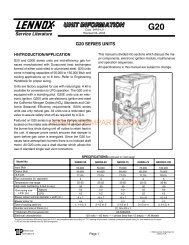
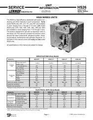
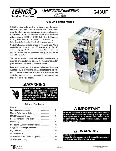
Service LiteratureCorp. 0416−L4Revised 2−2006G43UF SERIES UNITSG43UFG43UF series units are high−efficiency gas furnacesmanufactured with Lennox DuralokPlus aluminizedsteel clamshell−type heat exchangers, with a stainless steelcondensing coil. G43UF units are available in heating inputcapacities of 44,000 to 132,000 Btuh (13 to 38.6 kW) <strong>and</strong>cooling applications from 2 through 5 tons (7.0 through 17.6kW). Refer to Engineering H<strong>and</strong>book for proper sizing.Units are factory equipped for use with natural gas. A kit isavailable for conversion to LPG operation. All G43UFunits are equipped with a hot surface ignition system. Thegas valve is redundant to assure safety shut−off as requiredby C.S.A.The heat exchanger, burners <strong>and</strong> manifold assembly can beremoved for inspection <strong>and</strong> <strong>service</strong>. The maintenance sectiongives a detailed description on how this is done.Information contained in this <strong>manual</strong> is intended for use byqualified <strong>service</strong> technicians only. All specifications are subjectto change. Procedures outlined in this <strong>manual</strong> are presentedas a recommendation only <strong>and</strong> do not supersede orreplace local or state codes.WARNINGElectric shock hazard. Can cause injuryor death. Before attempting to performany <strong>service</strong> or maintenance, turn theelectrical power to unit OFF at disconnectswitch(es). Unit may have multiplepower supplies.Table of ContentsGeneral . . . . . . . . . . . . . . . . . . . . . . . . . . . . . . . . . . . . . . 1Specifications . . . . . . . . . . . . . . . . . . . . . . . . . . . . . . . . . 2Blower Performance Data . . . . . . . . . . . . . . . . . . . . . . 4I−Unit Components . . . . . . . . . . . . . . . . . . . . . . . . . . . . 9II Placement <strong>and</strong> Installation . . . . . . . . . . . . . . . . . . . . 18III−Start−Up . . . . . . . . . . . . . . . . . . . . . . . . . . . . . . . . . . . 31IV−<strong>Heating</strong> System Service Checks . . . . . . . . . . . . . . 32V−Typical Operating Conditions . . . . . . . . . . . . . . . . . 35High Altitude . . . . . . . . . . . . . . . . . . . . . . . . . . . . . . . . . . 35VI−Maintenance . . . . . . . . . . . . . . . . . . . . . . . . . . . . . . . 37VII−Wiring <strong>and</strong> Sequence of Operation . . . . . . . . . . . 39VIII−Troubleshooting . . . . . . . . . . . . . . . . . . . . . . . . . . . 49IMPORTANTImproper installation, adjustment, alteration, <strong>service</strong>or maintenance can cause property damage, personalinjury or loss of life. Installation <strong>and</strong> <strong>service</strong> mustbe performed by a qualified installer, <strong>service</strong> agencyor the gas supplier.WARNINGSharp edges.Be careful when servicing unit to avoid sharp edgeswhich may result in personal injury.Page 1© 2004 Lennox Industries Inc.Litho U.S.A.
SPECIFICATIONSGas<strong>Heating</strong>PerformanceModelNo.G43UF−24B−045G43UF−24B−070G43UF−36B−070G43UF−36C−090G43UF−36C−090HCanada OnlyInput− Btuh (kW) 44,000 (12.9) 66,000 (19.3) 66,000 (19.3) 88,000 (25.8) 88,000 (25.8)Output− Btuh (kW) 41,000 (12.0) 60,700 (17.8) 62,000 (18.2) 82,000 (24.0) 81,000 (23.7)1 AFUE 92.1% 90.0% 92.1% 92.1% 90.0%California Seasonal Efficiency 82.7% 84.2% 85.1% 85.2% 84.2%Highstatic(CSA)− in.w.g. (Pa) .50 (124) .50 (124) .50 (124) .50 (124) .50 (124)Temperature rise range − F (C) 30 − 60 (18 − 36) 50 − 80 (28 −44)Connectionsin40 − 70 (22 −39)40 − 70 (22 −39)50 − 80 (28 −44)2 Intake Pipe (PVC) 2 2 2 2 2in. 2 Exhaust Pipe (PVC) 2 2 2 2 2IndoorBlowerCondensate Drain Trap (PVC pipe) − i.d. 1/2 1/2 1/2 1/2 1/2with field supplied (PVC coupling) − o.d. 3/4 3/4 3/4 3/4 3/4hose with hose clamp − i.d. x o.d. 1−1/4 x 1 1−1/4 x 1 1−1/4 x 1 1−1/4 x 1 1−1/4 x 1GaspipesizeIPS 1/2 1/2 1/2 1/2 1/2Wheel nominal diameter xwidth −in. (mm)10 x 7(254 x 178)10 x 7(254 x 178)10 x 8(254 x 203)10 x 8(254 x 203)10 x 8(254 x 203)Motoroutput − hp (W) 1/5 (149) 1/5 (149) 1/3 (249) 1/3 (249) 1/3 (249)Tons(kW) ofadd-oncooling 1.5 − 2 (5.3 − 7.0) 1.5 − 2 (5.3 − 2 − 3 (8.8 − 10.5) 2 − 3 (7.0 − 10.5) 2 − 3 (7.0 − 10.5)7.0)ShippingData lbs. (kg) − 1 package 132 (60) 141 (64) 146 (66) 162 (74) 162 (74)Electricalcharacteristics120 volts − 60 hertz − 1 phase (less than 12 amps)SPECIFICATIONSGas<strong>Heating</strong>PerformanceModelNo.G43UF−48C−090G43UF−48C−110Input− Btuh (kW) 88,000 (25.8) 110,000(32.2)Output− Btuh (kW) 82,000 (24.0) 103,000(30.2)G43UF−48C−110HCanada Only110,000(32.2)101,000(29.6)G43UF−60C−110110,000(32.2)103,000(30.2)G43UF−60D−135132,000(38.7)123,000(36.0)1 AFUE 92.1% 92.1% 90.0% 92.1% 92.1%California Seasonal Efficiency 85.5% 86.2% 84.7% 85.6% 86.0%Highstatic(CSA)− in.w.g. (Pa) .50 (124) .50 (124) .50 (124) .50 (124) .50 (124)Temperature rise range − F (C) 40 − 70 (22 − 39) 45 − 75 (27− 45) 50 − 80 (28 − 44) 40 − 70 (22− 39) 45 − 75 (27− 45)Connections2 Intake Pipe (PVC) 2 2 2 2 3in. 2 Exhaust Pipe (PVC) 2 2 2 2 3IndoorBlowerCondensate Drain Trap (PVC pipe) − i.d. 1/2 1/2 1/2 1/2 1/2with field supplied (PVC coupling) − o.d. 3/4 3/4 3/4 3/4 3/4hose with hose clamp − i.d. x o.d. 1−1/4 x 1 1−1/4 x 1 1−1/4 x 1 1−1/4 x 1 1−1/4 x 1GaspipesizeIPS 1/2 1/2 1/2 1/2 1/2Wheelnominaldiameterxwidth −in. (mm)10 x 10(254 x 254)10 x 10(254 x 254)10 x 10(254 x 254)11−1/2 x 10(292 x 229)11−1/2 x 10(292 x 229)Motoroutput − hp (W) 1/2 (373) 1/2 (373) 1/2 (373) 1 (746) 1 (746)Tons(kW) ofadd-oncooling 3 − 4 (10.5 − 14) 3 − 4 (10.5 − 14) 3 − 4 (10.5 − 14) 4 − 5 (14 − 17.5) 4 − 5 (14 − 17.5)ShippingData lbs. (kg) − 1 package 168 (76) 178 (81) 178 (81) 186 (84) 203 (92)Electricalcharacteristics120 volts − 60 hertz − 1 phase (less than 12 amps)NOTE − Filters <strong>and</strong> provisions for mounting are not furnished <strong>and</strong> must be field provided.1 −Annual Fuel Utilization Efficiency based on DOE test procedures <strong>and</strong> according to FTC labeling regulations. Isolated combustion system rating for non-weatherized furnaces.2 Determine from venting tables proper exhaust pipe size <strong>and</strong> termination kit required.Page 2
OPTIONAL ACCESSORIES − MUST BE ORDERED EXTRAFILTER KITS1 <strong>Air</strong> Filter <strong>and</strong>Rack KitB" Width Models C" Width Models D" Width ModelsSide Return Single 44J22 44J22 44J22Ten Pack 66K63 66K63 66K63Size of filter − in. (mm) 16 x 25 x 1(406 x 635 x 25)16 x 25 x 1(406 x 635 x 25)16 x 25 x 1(406 x 635 x 25)EZ Filter Base Catalog No. − Ship. Wt. − lbs. (kg) 73P56 − 7 (3) 73P57 − 8 (4) 73P58 − 10 (5)Size of field provided filter − in.(mm)CABINET ACCESSORIES16 x 25 x 1(406 x 635 x 25)20 x 25 x 1(508 x 635 x 25)24 x 24 x 1(610 x 610 x 25)Return <strong>Air</strong> Base 76M88 74M74 74M75CONDENSATE DRAIN KITSCondensate Drain Heat Cable 6 ft. (1.8 m) 26K68 26K68 26K6824 ft. (7.3 m) 26K69 26K69 26K6950 ft. (15.2 m) 26K70 26K70 26K70Heat Cable Tape Fiberglass − 1/2 in. x 66 ft. 39G04 39G04 39G04Aluminum foil − 2 in. x 60 ft. 39G03 39G03 39G03Condensate Trap Alternate Location Kit − Up−Flow Only 76M20 76M20 76M20CONTROLSTwinning Kit 15L38 15L38 15L38TERMINATION KITS − See Installation Instructions for specific venting information.Termination Kits Concentric 1−1/2 in. (38 mm) 71M80 − − − − − −Direct VentApplications2 in. (51 mm) − − − 69M29 − − −Only 3 in. (76 mm) − − − 60L46 60L462 TerminationKits − Direct orNon−Direct VentWall − CloseCouple2 in. (51 mm) 22G44 − − − − − −3 in. (76 mm) 44J40 44J40 44J40Close Couple WTK − 2 in. (51 mm) 30G28 − − − − − −3 in. (76 mm) 81J20 81J20 81J20Roof 2 in. (51 mm) 15F75 15F75 15F75Wall − Wall RingKitRoof Termination Flashing Kit − Direct or Non−DirectVent − Contains two flashings.1 Cleanable polyurethane frame type filter.2 Kits contain enough parts for two, non−direct vent installations.3 Non−direct vent only.2 in (51 mm) 15F74 15F74 3 15F7444J41 44J41 44J41GAS HEAT ACCESSORIESInput Model No.1 High AltitudeOrifice KitNatural Gas OnlyHigh Altitude PressureSwitch Kit4501−7500 ft.(1372−2286 m)7501−10,000 ft.(2286−3048 m)0−7500 ft.(0−2286 m)LPG/Propane Kit7501−10,000 ft.(2286−3048 m)−045 G43UF 59M16 − − − 95M22 83M74 83M75−045−1 to −6 G43UF 59M16 − − − 56M06 83M74 83M75−070 G43UF 59M16 56M05 56M06 83M74 83M75−070−1 to −6 G43UF 59M16 − − − 56M06 83M74 83M75−090 G43UF 59M16 75M20 56M07 83M74 83M75−110 G43UF 59M16 75M20 56M07 83M74 83M75−135 G43UF 59M16 56M04 60M35 83M74 83M751 Required for proper operation at altitudes from 7501 to 10,000 ft. (2286 to 3048 m).Page 3
BLOWER/WATTS DATAG43UF−24B−045−1, −3 PERFORMANCEExternal <strong>Air</strong> Volume / Watts at Different Blower SpeedsStaticPressure High Medium Lowin.w.g.Pa cfm L/s Wattscfm L/s Watts cfmL/s Watts0.00 0 975 460 380 870 410 340 720 340 2850.10 25 935 440 365 855 400 335 710 335 2800.20 50 910 430 360 830 390 325 680 320 2700.30 75 870 410 345 795 375 310 655 310 2600.40 100 825 390 330 760 360 300 630 295 2550.50 125 760 360 315 715 335 285 610 290 2500.60 150 725 340 310 675 320 280 580 275 2350.70 175 680 320 295 630 300 265 545 260 2300.80 200 620 290 285 575 270 255 495 235 2200.90 225 555 260 270 520 245 245 425 200 205NOTES − All air data is measured external to unit with1 in. foam filter (not furnished − field provided).<strong>Air</strong> volume based on bottom air return air. Actual air volume may vary on side return air applications.G43UF−24B−070−1, −3 PERFORMANCEExternal <strong>Air</strong> Volume / Watts at Different Blower SpeedsStaticPressure High Medium Lowin.w.g.Pa cfm L/s Watts cfm L/s Watts cfm L/s Watts0.00 25 1020 480 380 905 430 345 740 350 2800.10 25 985 465 370 890 420 330 730 345 2700.20 50 945 445 355 860 405 325 705 330 2650.30 75 905 430 345 830 390 315 690 325 2600.40 100 860 405 330 790 370 300 660 310 2500.50 125 810 380 320 750 355 290 630 300 2400.60 150 740 350 305 710 335 280 590 280 2300.70 175 700 330 295 650 305 265 550 260 2200.80 200 635 300 280 590 280 255 495 235 2100.90 225 555 260 265 530 250 235 425 200 195G43UF−24B−045−4 PERFORMANCE (Less Filter)External Static<strong>Air</strong> Volume / Watts at Different Blower SpeedsPressure High Medium−High Medium−Low Lowin. w.g. Pa cfm L/s Watts cfm L/s Watts cfm L/s Watts cfm L/s Watts0.00 0 1125 530 425 900 425 360 745 350 295 690 325 2650.10 25 1115 525 410 905 425 350 760 360 285 695 330 2600.20 50 1090 515 395 895 420 335 755 355 280 685 325 2550.30 75 1060 500 380 880 415 325 740 350 270 675 320 2500.40 100 1020 480 365 860 405 315 720 340 260 665 315 2400.50 125 970 460 345 835 395 300 700 330 255 640 300 2300.60 150 920 435 335 795 375 290 665 315 240 600 285 2200.70 175 860 405 315 730 345 270 620 295 230 565 265 2150.80 200 760 360 295 665 315 250 560 265 215 510 240 2000.90 225 675 320 275 585 275 230 495 235 200 500 190 175G43UF−24B−070−4 PERFORMANCE (Less Filter)External Static<strong>Air</strong> Volume / Watts at Different Blower SpeedsPressure High Medium−High Medium−Low Lowin. w.g. Pa cfm L/s Watts cfm L/s Watts cfm L/s Watts cfm L/s Watts0.00 0 1115 525 435 875 415 360 720 340 290 665 315 2550.10 25 1115 525 425 865 410 350 725 340 285 670 315 2550.20 50 1100 520 415 870 410 335 730 345 280 665 315 2500.30 75 1080 510 400 870 410 330 725 340 270 655 310 2400.40 100 1050 495 385 855 405 320 715 335 265 645 305 2400.50 125 1010 475 365 835 395 310 695 330 255 625 295 2300.60 150 980 460 355 810 380 295 675 320 250 600 285 2250.70 175 930 440 340 770 365 285 640 300 235 565 265 2150.80 200 855 405 320 720 340 270 585 275 220 520 245 2000.90 225 770 365 295 650 305 250 525 245 205 465 220 190NOTES − All air data is measured external to unit without filter (not furnished − field provided).<strong>Air</strong> volume based on bottom air return air. Actual air volume may vary on side return air applications.Page 4
BLOWER/WATTS DATAG43UF−36B−070 PERFORMANCE (Less Filter)External Static<strong>Air</strong> Volume / Watts at Different Blower SpeedsPressure High Medium−High Medium−Low Lowin. w.g. Pa cfm L/s Watts cfm L/s Watts cfm L/s Watts cfm L/s Watts0.00 0 1640 775 660 1415 665 575 1160 545 485 1005 475 4100.10 25 1600 755 635 1395 660 550 1160 545 460 1000 470 3850.20 50 1540 725 605 1370 650 525 1160 545 445 995 470 3750.30 75 1495 705 580 1345 635 505 1145 540 425 990 465 3650.40 100 1420 670 545 1275 605 480 1125 530 395 965 455 3450.50 125 1360 640 525 1245 590 450 1080 510 375 945 445 3250.60 150 1275 600 490 1165 550 410 1025 485 350 900 425 3050.70 175 1170 555 465 1085 515 385 965 430 335 860 405 2950.80 200 1080 510 440 1010 475 360 865 410 310 775 365 2700.90 225 945 445 400 840 395 320 765 360 275 710 335 245NOTES − All air data is measured external to unit without filter (not furnished − field provided).<strong>Air</strong> volume based on bottom air return air. Actual air volume may vary on side return air applications.G43UF−36C−090(H) PERFORMANCE (Less Filter)External Static<strong>Air</strong> Volume / Watts at Different Blower SpeedsPressure High Medium−High Medium−Low Lowin. w.g. Pa cfm L/s Watts cfm L/s Watts cfm L/s Watts cfm L/s Watts0.00 0 1630 770 745 1360 640 635 1125 530 540 975 460 4400.10 25 1620 765 715 1365 645 610 1160 545 515 1000 470 4300.20 50 1590 750 680 1365 645 580 1160 545 495 990 465 4050.30 75 1550 730 655 1355 640 565 1170 550 475 985 465 3950.40 100 1520 715 630 1330 630 545 1160 545 460 980 460 3800.50 125 1465 690 605 1300 615 515 1140 540 440 960 455 3600.60 150 1415 670 570 1250 590 490 1095 515 420 940 445 3500.70 175 1350 635 545 1215 575 470 1065 500 400 905 425 3350.80 200 1260 595 510 1140 540 440 1005 475 375 850 400 3100.90 225 1165 550 475 1035 485 395 900 425 335 730 345 285NOTES − All air data is measured external to unit without filter (not furnished − field provided).<strong>Air</strong> volume based on bottom air return air. Actual air volume may vary on side return air applications.G43UF−48C−090 PERFORMANCE (Less Filter)External Static<strong>Air</strong> Volume / Watts at Different Blower SpeedsPressure High Medium−High Medium−Low Lowin. w.g. Pa cfm L/s Watts cfm L/s Watts cfm L/s Watts cfm L/s Watts0.00 0 2180 1030 930 1835 865 790 1520 715 630 1280 605 5100.10 25 2135 1005 885 1825 860 750 1510 710 610 1275 600 4950.20 50 2085 985 840 1810 855 720 1505 710 580 1270 600 4750.30 75 2030 955 800 1775 835 685 1500 705 565 1265 595 4600.40 100 1940 915 760 1735 820 650 1480 700 535 1250 590 4400.50 125 1865 880 725 1660 785 600 1430 675 505 1215 575 4250.60 150 1740 820 670 1590 750 575 1380 650 475 1175 555 4100.70 175 1645 775 640 1475 695 520 1290 610 450 1105 520 3750.80 200 1540 725 600 1340 630 465 1175 555 405 1020 480 3550.90 225 1335 630 540 1170 555 440 1070 505 375 950 450 330NOTES − All air data is measured external to unit without filter (not furnished − field provided).<strong>Air</strong> volume based on bottom air return air. Actual air volume may vary on side return air applications.Page 5
BLOWER/WATTS DATAG43UF−60D−135 PERFORMANCE (Less Filter) − Single Side Return <strong>Air</strong> − <strong>Air</strong> volumes in bold require field fabricated transitionto accommodate 20 x 25 x 1 in. (508 x 635 x 25 mm) air filter in order to maintain proper air velocity.External Static<strong>Air</strong> Volume / Watts at Different Blower SpeedsPressureHigh Medium−High Medium−Low Lowin. w.g. Pa cfm L/s Watts cfm L/s Watts cfm L/s Watts cfm L/s Watts0.00 0 2665 1260 1440 2325 1095 1100 1865 880 890 1410 665 6900.10 25 2615 1235 1405 2310 1090 1065 1915 905 865 1465 690 6850.20 50 2530 1195 1370 2280 1075 1055 1925 910 850 1570 740 6750.30 75 2470 1165 1330 2235 1055 1015 1920 905 825 1590 750 6700.40 100 2380 1125 1290 2175 1025 985 1910 900 805 1590 750 6550.50 125 2310 1090 1265 2120 1000 965 1890 890 790 1595 755 6450.60 150 2200 1035 1230 2055 970 935 1835 865 765 1580 745 6300.70 175 2120 1000 1190 1970 930 900 1790 845 740 1545 730 6050.80 200 2025 955 1160 1890 890 875 1720 810 710 1515 715 5900.90 225 1930 910 1110 1800 850 835 1655 780 685 1440 680 570NOTES − All air data is measured external to unit without filter (not furnished − field provided).G43UF−60D−135 PERFORMANCE (Less Filter) − Bottom Return <strong>Air</strong>, Side Return <strong>Air</strong> with Optional RAB Return <strong>Air</strong> Base,Return <strong>Air</strong> from Both Sides or Return <strong>Air</strong> from Bottom <strong>and</strong> One Side.External Static<strong>Air</strong> Volume / Watts at Different Blower SpeedsPressureHigh Medium−High Medium−Low Lowin. w.g. Pa cfm L/s Watts cfm L/s Watts cfm L/s Watts cfm L/s Watts0.00 0 2730 1290 1465 2425 1145 1125 2055 970 915 1560 735 6800.10 25 2670 1260 1440 2400 1135 1100 2065 975 890 1590 750 6750.20 50 2600 1225 1400 2365 1115 1070 2045 965 865 1620 765 6650.30 75 2525 1190 1360 2315 1095 1045 2035 960 845 1615 760 6550.40 100 2445 1155 1325 2260 1065 1015 2020 955 820 1615 760 6450.50 125 2360 1115 1280 2195 1035 985 1960 925 790 1610 760 6350.60 150 2290 1080 1255 2130 1005 965 1900 895 755 1600 755 6150.70 175 2205 1040 1220 2035 960 910 1825 860 730 1570 740 6000.80 200 2110 995 1195 1945 915 880 1765 830 710 1540 725 5800.90 225 1970 930 1120 1835 865 830 1680 795 690 1540 725 545NOTES − All air data is measured external to unit without filter (not furnished − field provided).Page 7
TABLE 1SureLight BOARD J156 (J2) TERMINALDESIGNATIONSPIN #FUNCTION1 Combustion <strong>Air</strong> Inducer Line2 Ignitor Line3 Combustion <strong>Air</strong> Inducer Neutral4 Ignitor NeutralTABLE 2SureLight BOARD J58 (J1) TERMINALDESIGNATIONSPIN #FUNCTION1 High Limit Output2 Not Used3 24V Line4 Not Used5 Rollout Switch In6 24V Neutral7 High Limit Input8 Ground9 Gas Valve In10 Pressure Switch Out11 Rollout Switch Out12 Gas Valve OutTABLE 3TERMINAL DESIGNATIONSCOOL−H 120V HOT Blower Cooling Speed (120VAC)HEAT−HBlower <strong>Heating</strong> Speed−(120VAC)EAC−HElectronic <strong>Air</strong> Cleaner (120VAC)HUM−HHumidifier (120VAC)XFMR−HTransformer (120VAC)LINE−HInput (120VAC)LINE−N 120V NEUT Input (Neutral)HUM−NHumidifier (Neutral)EAC−NElectronic <strong>Air</strong> Cleaner (Neutral)XFMR−NTransformer (Neutral)CIR−NBlower (Neutral)PARKAlternate Blower Speeds (dead)(FLAME SENSE)Flame SensorElectronic Ignition (See Figure 5)On a call for heat the SureLight ® control board monitors thecombustion air inducer prove switch. The control will notbegin the heating cycle if the prove switch is closed (by−passed). Once the prove switch is determined to be open,the combustion air inducer is energized. When the differentialin the prove switch is great enough, the prove switchcloses <strong>and</strong> a 15−second pre−purge begins. If the proveswitch is not proven within 2−1/2 minutes, the control goesinto Watchguard−Pressure Switch mode for a 5−minute re−set period.After the 15−second pre−purge period, the SureLight ignitorwarms up for 20 seconds during which the gas valve opensat 19 seconds for a 4−second trial for ignition. The ignitorstays energized during the 4 second trial until flame issensed. If ignition is not proved during the 4−second period,the control will try four more times with an inter purge <strong>and</strong>warm−up time between trials of 35 seconds. After a total offive trials for ignition (including the initial trial), the controlgoes into Watchguard−Flame Failure mode. After a 60−minutereset period, the control will begin the ignition sequenceagain.The SureLight control board has an added feature that prolongsthe life of the ignitor. After a successful ignition, theSureLight control utilizes less power to energize the ignitoron successive calls for heat. The control continues to rampdown the voltage to the ignitor until it finds the lowestamount of power that will provide a successful ignition. Thisamount of power is used for 255 cycles. On the 256th callfor heat, the control will again ramp down until the lowestpower is determined <strong>and</strong> the cycle begins again. Each time120V is removed <strong>and</strong> then re−applied, the control re−startsthe learning process.Fan Time ControlThe fan on time of 45 seconds is not adjustable. Fan offtime (time that the blower operates after the heat dem<strong>and</strong>has been satisfied) can be adjusted by setting the dipswitches located on the control board. The unit is shippedwith a factory fan off setting of 90 seconds. For customizedcomfort, monitor the supply air temperature once the heatdem<strong>and</strong> is satisfied. Note the supply air temperature at theinstant the blower is de−energized. Adjust the fan−off delayto achieve a supply air temperature between 90° − 110° atthe instant the blower is de−energized. (Longer delay timesallow for lower air temperature, shorter delay times allowfor higher air temperature). See figure 4.OFFOFFFAN-OFF TIME ADJUSTMENT60sec. 90sec. 120sec. 180sec.ON12OFF ON OFF ON OFF ONOFF12(Black square indicates switch position)To adjust fan−off timing, flip dip switch to desired setting.OFFFIGURE 412OFF12Page 10
The integrated ignition control board is equipped with two LED lights for troubleshooting. The diagnostic codes are listedbelow in table 4.TABLE 4DIAGNOSTIC CODESMake sure to Identify LED’S Correctly..LED#132M88 − DS1 Green78M47 − DS1 RedSIMULTANEOUSSLOW FLASHSIMULTANEOUSFAST FLASHSLOW FLASHOFFALTERNATINGSLOW FLASHLED #232M88 − DS2 Green78M47 − DS2 GreenSIMULTANEOUSSLOW FLASHSIMULTANEOUSFAST FLASHONSLOW FLASHALTERNATINGSLOW FLASHDESCRIPTIONPower on − Normal operation.Also signaled during cooling <strong>and</strong> continuous fan.Normal operation − signaled when heating dem<strong>and</strong> initiated at thermostat.Primary or secondary limit switch open. Limit must close within 3 minutes orunit goes into 1 hour Watchguard.Prove switch open.OR:Blocked inlet/exhaust vent;OR: Prove switch closed prior to activation of combustion air inducer.Watchguard −− burners failed to igniteOR: limit open more than 3 minutes (control board 32M88 Only)OR: lost flame sense 5 times in one heating cycleOR: prove switch opened 5 times in one heating cycleSLOW FLASH OFF Flame sensed without gas valve energized.ON SLOW FLASH Rollout switch open. OR: 12-pin connector improperly attached.ONONON OFF Circuit board failure or control wired incorrectly.OFFONFAST FLASH SLOW FLASH Main power polarity reversed. Switch line <strong>and</strong> neutral.SLOW FLASHFAST FLASHLow flame signal. Measures belowControl board 32M88 − 0.18 microampsControl board 78M47 & 100973−01 − 1.5 microampsReplace flame sense rod.ALTERNATINGFAST FLASHALTERNATINGFAST FLASHThe following conditions are sensedImproper main ground (control board 32M88) during the ignitor warm−up periodONLY Improper main ground (control board 78M47 & 100973−01) continuouslyOR: Broken ignitor (control board 32M88)OR: Open ignitor circuit (control board 32M88)OR: Line voltage to control belowControl board 32M88 75VControl board 78M47 & 100973−01 90VNOTE − Slow flash rate equals 1 Hz (one flash per second). Fast flash rate equals 3 Hz (three flashes per second).Low flame sense current = SureLight Control Board 32M88 0.16 − 0.17 microamps Ignition Control Board 78M47 & 100973−01 0.5 − 1.4 microampsÉÉÉÉONOFFDEMAND ÉÉCAIIGNITOR**GAS VALVEINDOOR BLOWER15 Sec.Pre −Purge20 sec.Ignitor Warmup4 Sec.Trialfor IgnitionBlower On"DelayEnd ofHeat Dem<strong>and</strong>5 SECPostPurgeÉÉÉÉÉÉÉÉÉÉÉÉÉÉÉÉÉÉÉÉÉÉÉÉÉÉÉÉÉÉÉÉÉÉÉÉÉÉÉÉÉÉÉÉÉÉÉÉÉÉBlowerOffTimeÉÉÉÉÉÉÉÉÉÉÉÉÉÉÉÉÉÉÉ*Blower on time will be 45 seconds after gas valve is energized. Blower off time will depend on OFF TIME" Setting.** Ignitor on ignition control board 78M47 & 100973−01 equipped units will energize for the first 3 seconds of the 4second trial, following the ignitor 20 second warm up .FIGURE 5ÉÉÉÉÉÉÉÉÉÉÉÉÉÉÉÉÉÉÉÉÉÉPage 11
SURELIGHT ® INTEGRATED CONTROL BOARD32M88FIGURE 6J58J156XFMR-N4. Ignition Control 78M47 & 100973−01 (A92)G43UF−2 <strong>and</strong> later unitsWARNINGShock hazard.Disconnect power before servicing. Control isnot field repairable. If control is inoperable, simplyreplace entire control.Can cause injury or death. Unsafe operation willresult if repair is attempted.The ignition control system consists of an integrated controlboard (figure 8 with control terminal designations intable 7), ignitor (figure 9) <strong>and</strong> sensor (figure 10). The controlboard <strong>and</strong> ignitor work in combination to ensure furnaceignition <strong>and</strong> ignitor durability. The control board controlsall major furnace operations. The control board alsofeatures two LED lights (DS1 red <strong>and</strong> DS2 green) for troubleshooting<strong>and</strong> two accessory terminals rated at (1) oneamp. The control board also features a (3) amp fuse forovercurrent protection. Tables 5 <strong>and</strong> 6 show jack plug terminaldesignations. See table 4 for troubleshooting diagnosticcodes. The mini−nitride ignitor is made from a non−porous, high strength proprietary ceramic material thatprovides long life <strong>and</strong> trouble free maintenance. The controlboard continuosly monitors line voltage <strong>and</strong> maintainsthe ignitor power at a consistent level to provide properlighting <strong>and</strong> maximum ignitor life.TABLE 54−Pin Terminal DesignationPIN #FUNCTION1 Combustion <strong>Air</strong> Inducer Line2 Ignitor Line3 Combustion <strong>Air</strong> Inducer Neutral4 Ignitor NeutralTABLE 612−Pin Terminal DesignationsPIN #FUNCTION1 High Limit Output2 Not Used3 24V Line4 Not Used5 Rollout Switch Out6 24V Neutral7 High Limit Input8 Ground9 Gas Valve Common10 Prove Switch In11 Rollout Switch In12 Gas Valve OutCOOLHEATPARKPARKEACXFMRLINEHUMCIRCXMFRHUMLINEFlame FSTABLE 7TERMINAL DESIGNATIONS120 Volt HotCool SpeedHeat SpeedParkParkElectrconic <strong>Air</strong> CleanerTransformerLineHumidifier120 Volt NeutralBlowerTransformerHumidifierLineFlame SignalElectronic Ignition (See Figure 5)On a call for heat the ignition control board monitors thecombustion air inducer prove switch. The control board willnot begin the heating cycle if the prove switch is closed (by−passed). Once the prove switch is determined to be open,the combustion air inducer is energized. When the differentialin the prove switch is great enough, the prove switchcloses <strong>and</strong> a 15−second pre−purge begins. If the proveswitch is not proven within 2−1/2 minutes, the control boardgoes into Watchguard−Pressure Switch mode for a 5−minutere−set period.Page 12
After the 15−second pre−purge period, the ignitor warms upfor 20 seconds during which the gas valve opens at 19 secondsfor a 4−second trial for ignition. The ignitor remainsenergized for the first 3 seconds during the 4 second trial. Ifignition is not proved during the 4−second period, the controlwill try four more times with an inter purge <strong>and</strong> warm−uptime between trials of 35 seconds. After a total of five trialsfor ignition (including the initial trial), the control goes intoWatchguard−Flame Failure mode. After a 60−minute resetperiod, the control will begin the ignition sequence again.The control board has an added feature of ignitor powerregulation to maintain consistent lighting <strong>and</strong> longer ignitorlife under all line voltage conditions.Fan Time ControlThe fan on time of 45 seconds is not adjustable. Fan offtime (time that the blower operates after the heat dem<strong>and</strong>has been satisfied) can be adjusted by moving the jumperto a different setting. The unit is shipped with a factory fanoff setting of 90 seconds. For customized comfort, monitorthe supply air temperature once the heat dem<strong>and</strong> is satisfied.Note the supply air temperature at the instant theblower is de−energized. Adjust the fan−off delay to achievea supply air temperature between 90° − 110° at the instantthe blower is de−energized. (Longer delay times allow forlower air temperature, shorter delay times allow for higherair temperature). See figure 7.Board 100973−01 only has a 45 second fan off delay aftercooling dem<strong>and</strong> is met. This timing is factory set <strong>and</strong> cannotbe adjusted.FAN-OFF TIME ADJUSTMENTTo adjust fan−off timing, reposition jumper across pins toachieve desired setting.FIGURE 7DS1REDDS2GREENIGNITION CONTROL BOARDFIGURE 8C−<strong>Heating</strong> ComponentsCombustion air inducer (B6), primary limit control (S10),SureLight ignitor, burners, flame rollout switch (S47), gasvalve (GV1), combustion air prove switch (S18), <strong>and</strong> clamshellheat exchangers are located in the heating compartment.The heating compartment can be accessed by removingthe burner access panel.1. Ignitor (Figure 9)The SureLight ignitor used on G43UF−1 units, is made ofdurable silicon nitride. The board finds the lowest ignitortemperature which will successfully light the burner, thusincreasing the life of the ignitor. Due to this feature of theboard, voltage cannot be measured. The check ignitor,measure its resistance. A value of 10.9 to 19.7 ohms indicatesa good ignitor.The ignitor used on G43−2 <strong>and</strong> later units use a mini−nitrideignitor made from a proprietary ceramic material. Ignitorlongevity is enhanced by controlling the voltage to the ignitor.The check ignitor, measure its resistance. A value of 50to 450 ohms indicates a good ignitor.Page 13
B"Ignitor LocationIGNITOR TYPE A" B"Silicon nitride .625 .406Mini NitrideA".685 .306MEASUREMENT IS TO I.D.OF RETENTION RINGBRACKET3. Primary Limit Control (S10)Figure 11 shows the primary limit (S10) used on G43UF unitslocated in the heating vestibule panel. S10 is provided with ashield on some models (figure 11) <strong>and</strong> must not be removed.Note orientation of shield <strong>and</strong> limit if limit is replaced. When excessheat is sensed in the heat exchanger, the limit will open.Once the limit opens, the furnace control energizes thesupply air blower <strong>and</strong> de−energizes the gas valve. The limitautomatically resets when unit temperature returns to normal.The switch is factory set <strong>and</strong> cannot be adjusted.PRIMARY LIMIT LOCATIONBURNERS FRONT VIEWFIGURE 92. Flame Sensor (Figure 10)A flame sensor is located on the left side of the burner support.The sensor is mounted on the bottom burner box plate<strong>and</strong> the tip protrudes into the flame envelope of the left−most burner. The sensor can be removed for <strong>service</strong> withoutremoving any part of the burners. During operation,flame is sensed by current passed through the flame <strong>and</strong>sensing electrode. The ignition control allows the gas valveto remain open as long as flame signal is sensed.NOTE − The G43UF furnace contains electronic componentsthat are polarity sensitive. Make sure that thefurnace is wired correctly <strong>and</strong> is properly grounded.5/16"FIGURE 10limit shield090, −110 <strong>and</strong>−135 onlylimit faces shieldFIGURE 114. Burners (Figure 12)All units use inshot burners. Burners are factory set <strong>and</strong> do notrequire adjustment. Burners can be removed as an assemblyfor <strong>service</strong>. Burner maintenance <strong>and</strong> <strong>service</strong> is detailed in theMAINTENANCE section of this <strong>manual</strong>. Each burner usesan orifice which is precisely matched to the burner input. AllG43UF natural gas units are fitted with .089" sized orifices.See table 20 or SPECIFICATIONS" tables for LP kits <strong>and</strong>high altitude. The orifice is threaded into the burner manifold.The burner is supported by the orifice <strong>and</strong> will easily slide offfor <strong>service</strong>. A flame retention ring in the end of each burnermaintains correct flame length <strong>and</strong> shape <strong>and</strong> keeps the flamefrom lifting off the burner head. In addition, the burner entranceto each clamshell is fitted with a corbel cup (orifice) used todirect the flow of combustion products.NOTE − Do not use thread-sealing compound on the orifices.Thread-sealing compound may plug the orifices.Page 14
BURNER DETAIL TOP VIEWBURNER BOX ASSEMBLYROLLOUT SWITCH(each side)5/16"ignitorFIGURE 125. Clamshell Heat ExchangerG43UF units use an aluminized steel primary <strong>and</strong> stainlesssteel secondary heat exchanger assembly. Heat istransferred to the air stream from all surfaces of the heatexchanger. The shape of the heat exchanger ensuresmaximum efficiency.The combustion air inducer pulls fresh air through the airintake box. This air is mixed with gas in the burner venturi<strong>and</strong> at the corbel orifices. The gas / air mixture is thenburned at the entrance of each clamshell. Combustiongases are then pulled through the primary <strong>and</strong> secondary heatexchangers <strong>and</strong> exhausted out the exhaust vent pipe.6. Backup Secondary Limit Control (S113)(G43UF−090, 110, 135 only)Backup secondary limit control S113 is a N.C. auto−resetswitch located on the combustion air inducer. S113 acts asa backup to primary limit S10 in the event of an indoor blowerfailure. S113 contacts open when temperature on theCAI reaches 142°.7. Flame Rollout Switches (S47)Flame rollout switches S47 are SPST N.C. high temperaturelimits located on each side of the burner box assembly (seefigure13). S47 is wired to the burner ignition control A92.When either of the switches sense flame rollout (indicatinga blockage in the combustion passages), the flamerollout switch trips, <strong>and</strong> the ignition control immediatelycloses the gas valve. Switch S47 in all G43UF units is factorypreset to open at 250F + 12F (121C + 6.7C) on atemperature rise. All flame rollout switches are <strong>manual</strong> reset.FIGURE 138. Gas Valve (GV1)The G43UF uses a gas valve manufactured by Honeywell orWhite Rodgers (see figure 14 ). The valves are internally redundantto assure safety shut-off. If the gas valve must be replaced,the same type valve must be used.24VAC terminals <strong>and</strong> gas control knob are located ontop of the valve. All terminals on the gas valve are connectedto wires from the ignition control. 24V applied to theterminals opens the valve.Inlet <strong>and</strong> outlet pressure taps are located on the valve. Amanifold adjustment screw is also located on the valve.An LPG changeover kit is available. See table 20. Forunits equipped with the Honeywell VR205 valve, the kitincludes a low pressure switch that must be installed inthe valve as shown in figure 14.The burner box is sealed <strong>and</strong> operates under a negativepressure. A pressure hose is connected from the burnerbox to the gas valve. The gas valve senses the pressure inthe burner box <strong>and</strong> changes gas valve outlet (manifold)pressure based on changes in the burner box pressure.The intent is to compensate for different vent configurationswhich can greatly affect the rate of the unit.IMPORTANTThe White Rodgers 36G gas valve (figure 14) isequipped with pressure posts for measuring supply<strong>and</strong> manifold pressures. The posts provide built−inhose connections <strong>and</strong> have an integral 3/32" Allen−head screw. Rotate the screw counterclockwise onefull turn to permit pressure measurement. Reseat thescrew (rotate one full turn clockwise) after measurementshave been taken to prevent gas leakage.Page 15
HONEYWELL VR8205 SERIES GAS VALVEPRESSURESWITCH(LP ONLY)WHITE RODGERS 36G SERIES GAS VALVEMANIFOLD PRESSUREOUTLET POSTREFERENCETO BURNERBOXMANIFOLDPRESSUREADJUSTMENTLINE PRESSURESCREWINLET POSTGAS VALVE SHOWN IN OFF POSITIONFIGURE 14BARBEDFITTINGMANIFOLDPRESSUREOUTLETONINLETPRESSUREOFFPORT WITHINLET TAPFITTINGHONEYWELL VR8205 SERIES GAS VALVEMANIFOLDPRESSUREADJUSTMENTSCREW(under cap)(With On/Off Switch)MANIFOLDPRESSUREOUTLETLINE PRESSUREINLET POSTGAS VALVE ON/OFF SWITCH SHOWN IN ON POSITION9. Combustion <strong>Air</strong> Inducer (B6)& Cold End Header BoxAll G43UF units use a combustion air inducer to move airthrough the burners <strong>and</strong> heat exchanger during heatingoperation. The blower uses a shaded pole 120VAC motor.The motor operates during all heating operation <strong>and</strong> iscontrolled by burner ignition control A3. Blower operatescontinuously while there is a call for heat. The burner ignitioncontrol will not proceed with the ignition sequence untilcombustion air inducer operation is sensed by the provingswitches.The CAI is installed on the cold end header box. The coldend header box is a single piece made of hard plastic.The box has an internal channel where the combustionair inducer creates negative pressure at unit start up. Thechannel contains an orifice used to regulate flow createdby the CAI. The box has pressure taps for the CAI proveswitch hoses. The prove switch measure the pressureacross the CAI orifice or difference in the channel <strong>and</strong> thebox. A window is provided on the bottom right h<strong>and</strong> sideof the box to indicate orifice size. See figures 15 <strong>and</strong> 17.See table 8 for orifice size per unit. If replacement isnecessary the gaskets used to seal the box to thevestbule panel <strong>and</strong> the CAI to the box, must also bereplaced.WARNINGCARBON MONOXIDE POISONING HAZARDDo not install a header box designed for the G51 orG61 furnace onto a G43 furnace. Header boxes forG51 <strong>and</strong> G61 furnaces are equipped with opendrain ports in the upper corners of the box, whichallow bypass of the proper flow of combustion airto the burners. Differences in header box areshown in figure 15.When replacing a G43 header box, ensure that thereplacement box is equipped with the same orificesize <strong>and</strong> number of drain <strong>and</strong> pressure ports as theoriginal. G43 header boxes are GRAY in color. G51<strong>and</strong> G61 series header boxes are BLACK in color.TABLE 8G43UF UnitC.A.I. Orifice Size−045−1 to −6 .750"−045−7 <strong>and</strong> later .703"−070−7 <strong>and</strong> later .922"−070−1 to −6 .969"−090 1.063"−110 1.344"−135 1.625"Page 16
COLD END HEADER BOXESG43(gray in color)PRESSURETAPSPRESSURETAPSG51 / G61(black in color)FIGURE 15CLOSED DRAIN PORTS(BOTH SIDES)ORIFICEORIFICEORIFICE SIZE IDPRESSURETAPSOPEN DRAIN PORTS(BOTH SIDES)ORIFICE SIZE ID10. Combustion <strong>Air</strong> Prove Switch (S18)G43UF series units are equipped with a differentialprove switch located on the combustion air inducerhousing. See figures 16 <strong>and</strong> 17. One side of the switch isgray (negative hose barb) <strong>and</strong> the other side is black (positivehose barb). The switches monitor across the CAI orifice to insureproper flow through the heat exchanger.The switch is a SPST N.O. prove switch electrically connectedto the integrated control. The purpose of the switch isto prevent burner operation if the combustion air inducer is notmoving enough air for proper combustion.bracketPROVE SWITCH (S18)side view negative (−) barbgrayterminalsFIGURE 16positive (+) barbblackOn start-up, the switch senses that the combustion air induceris operating. It closes a circuit to the ignition control whenthe difference in pressure across the CAI orifice exceeds anon−adjustable factory setting. If the switch does not successfullysense the required differential, the switch cannotclose <strong>and</strong> the furnace cannot operate. If the flue orair inlet become obstructed during operation, the switchsenses a loss of pressure differential <strong>and</strong> opens the circuit tothe ignition control. If the condensate line is blocked, waterwill back up into the header box <strong>and</strong> reduce the pressure differentialacross the switch. The prove switch opens if the differentialdrops below the set point. See table 9.Checks of pressure differential can aid in troubleshooting.When measuring the pressure differential, readings should betaken at the prove switch. Lack of differential usually indicatesproblems in the intake or exhaust piping, but may indicateproblems in the heat exchanger, condensing coil, headerboxes, combustion inducer or other components.TABLE 9Altitude ft0 − 4500 4501 − 7500 7501 − 10000G43UFSet Point(Pa)SetPoint(Pa)Set Point(Pa)−045−7<strong>and</strong> later1.10"(274) 1.10" (274) 1.00" (249)−045−1 to−6 units.95" (236) .95" (236) .85" (211)−070−7<strong>and</strong> later1.00"(249) .95" (236) .85" (211)−070−1 to−6 units.95" (236) .95" (236) .85" (211)−090−110.85" (211) .75" (186) .65" (162)−135 .65 (162) .55" (137) .45" (112)*Set point is factory set <strong>and</strong> non−adjustable**See table 20 for high altitude kits.Measuring pressure differentialThe differential pressure is the difference in pressure measuredacross the cold end header box orifice.1 − Remove thermostat dem<strong>and</strong> <strong>and</strong> allow unit to cycleoff.2 − Install a tee in the negative (−) line <strong>and</strong> a tee in the positive(+) line running from the prove switch to the cold endheader box.3 − Install a manometer with hose from the negative (−)side of the manometer to the tee installed in the negative(−) line <strong>and</strong> with hose from the positive (+) side ofthe manometer to the tee in the positive (+) line.NOTE − Both sides of the cold end header box are negative.However the (+) port reads less negative pressure than the(−) port.Page 17
CAI & COLD END HEADER BOX ASSEMBLYInstall tee’s in thenegative line <strong>and</strong>positive line thenconnect hoses tomanometer.cold end header box− +prove switchFIGURE 17orifice size4 − Operate unit <strong>and</strong> observe draft gauge reading. Readingswill change as heat exchanger warms.a. Take one reading immediately after start-up.b. Take a second reading after unit has reached steadystate (approximately 5 minutes). This will be the pressuredifferential.The pressure differential should be greaterthan those listed in table 9.5 − Remove thermostat dem<strong>and</strong> <strong>and</strong> allow to cycle off.6 − Remove manometer <strong>and</strong> tee’s. Reinstall combustion airsensing hoses to the prove switch.D−Blower CompartmentBlower motor (B3) <strong>and</strong> capacitor (C4), are located in theblower compartment. The blower compartment can be accessedby removing the blower access panel.1.Blower Motor (B3) <strong>and</strong> Capacitor (C4)All G43UF units use single−phase direct−drive blower motors.All motors are 120V permanent split capacitor motorsto ensure maximum efficiency. See SPECIFICATIONS tableat the front of this <strong>manual</strong> for more detail. See motor nameplatefor capacitor ratings.Page 18
II−PLACEMENT AND INSTALLATIONTable 10 lists the available exhaust termination kits. All Lennoxvent terminations are PVC or ABS.UNITMODEL24B−04536B−04536B−07036C−09048C−09048C−11060C−11060D−135VENTPIPEDIA.(in.)OutdoorExhaustAccelerator(Dia. XLength)OutdoorExhaustAccelerator(Dia. XLength)1−1/2"ConcentricKitTABLE 10TERMINATION KITSVent Pipe Length Equivalency (feet)2" ConcentricKit3" ConcentricKit2" WallPlate Kit1−1/2" X 12" 2" X 12" 71M80 60M29 60L46 22G442 4 NotAllowed2−1/2 5 NotAllowed3 7 NotAllowed4 14 NotAllowed2 4 NotAllowed2−1/2 5 NotAllowed3 8 NotAllowed4 14 NotAllowed2 NotAllowed2−1/2 NotAllowed3 NotAllowed4 NotAllowed2 NotAllowed2−1/2 NotAllowed3 NotAllowed4 NotAllowed3 NotAllowed4 NotAllowed1 NotAllowed2 NotAllowed2 NotAllowed4 NotAllowed1 NotAllowed2 NotAllowed2 NotAllowed4 NotAllowed6 NotAllowed10 NotAllowed12 NotAllowed15 NotAllowed21 NotAllowed42 NotAllowed12 NotAllowed15 NotAllowed24 NotAllowed42 NotAllowedNotAllowedNotAllowedNotAllowedNotAllowedNotAllowedNotAllowedNotAllowedNotAllowed3 3 NotAllowed6 6 NotAllowed6 6 NotAllowed12 12 NotAllowed3 3 NotAllowed6 6 NotAllowed6 6 NotAllowed12 12 NotAllowedNotAllowedNotAllowed15 NotAllowed25 NotAllowed3" WallPlate Kit44J4081J202" WallKit withVent Extension30G282" WallRing Kit15F744 4* 4 45 5* 5 57 7* 7 714 14* 14 144 4* 4 45 5* 5 58 8* 8 814 14* 14 141 NotAllowed2 NotAllowed2 NotAllowed4 NotAllowed1 NotAllowed2 NotAllowed2 NotAllowed4 NotAllowed6 NotAllowed10 NotAllowed*Requires field−provided <strong>and</strong> installed 1−1/2" exhaust accelerator.**Requires field−provided <strong>and</strong> installed 2" exhaust accelerator.***For use only in non−direct vent applications, when snow riser is not required. Requires field−provided <strong>and</strong> installed 2" exhaust accelerator.***For use only in non−direct vent applications.1**2**2**4**1**2***2***4***6***10***Page 19
A−Vent Piping GuidelinesThe G43UF can be installed as either a Non−Direct Ventor a Direct Vent gas central furnace.NOTE − In Non-Direct Vent installations, combustion air istaken from indoors <strong>and</strong> flue gases are discharged outdoors.In Direct Vent installations, combustion air is taken from outdoors<strong>and</strong> flue gases are discharged outdoors.Intake <strong>and</strong> exhaust pipe sizing in Direct Vent applications<strong>and</strong> exhaust pipe sizing in Non-Direct Vent applications −−Size pipe according to tables 11, 12 (direct vent) <strong>and</strong> 13(non−direct vent). Table 11 lists the minimum equivalentvent pipe lengths permitted. Tables 12 <strong>and</strong> 13 list the maximumequivalent pipe lengths permitted.Maximum vent length is defined as:Total length (linear feet) of pipe,Plus Equivalent length (feet) of fittings,Plus Equivalent length (feet) of termination.NOTE − Include ALL pipe <strong>and</strong> ALL fittings, both indoors <strong>and</strong> outdoors.Regardless of the diameter of pipe used, the st<strong>and</strong>ard roof<strong>and</strong> wall terminations described in section Exhaust PipingTerminations should be used. Exhaust vent terminationpipe is sized to optimize the velocity of the exhaust gas asit exits the termination. Refer to table 14.NOTE − The exhaust pipe should be offset a minimum of 12inches to avoid the possibility of water droplets being releasedfrom the exhaust termination. The minimum exhaustvent length is 15 ft. Shorter exhaust vent lengths mayresult in the discharge of water droplets from the exhausttermination, in spite of the 12−inch vertical offset.Each 90° elbow (including those provided with the furnace)of any diameter is equivalent to 5 feet (1.52m) of vent pipeof the same diameter. Two 45° elbows are equivalent toone 90° elbow of the same diameter. One 45° elbow isequal to 2.5 feet (.76m) of vent pipe of the same diameter.In some applications which permit the use of several differentsizes of vent pipe, a combination vent pipe may beused. Contact the Application Department for assistance insizing vent pipe in these applications.NOTE − The flue collar on all models is sized to accommodate2" Schedule 40 flue pipe. When vent pipe which islarger than 2" must be used in an upflow application, a 2"elbow must be applied at the flue collar in order to properlytransition to the larger diameter flue pipe. This elbowmust be added to the elbow count used to determine acceptablevent lengths. Assign an equivalent feet value tothis elbow according to the larger size pipe being used.Contact the Application Department for more informationconcerning sizing of vent systems which include multiplepipe sizes.Use the following steps to correctly size vent pipe diameter.1 − Determine the vent termination <strong>and</strong> its correspondingequivalent feet value according to table 10.2 − Determine the number of 90° elbows required for bothindoor <strong>and</strong> outdoor (e.g. snow riser) use. Calculate thecorresponding equivalent feet of vent pipe.3 − Determine the number of 45° elbows required for bothindoor <strong>and</strong> outdoor use. Calculate the correspondingequivalent feet of vent pipe.4 − Determine the length of straight pipe required.5 − Add the total equivalent feet calculated in steps 1through 4 <strong>and</strong> compare that length to the maximumvalues given in table 12 or 13 for the proposed ventpipe diameter. If the total equivalent length requiredexceeds the maximum equivalent length listed in theappropriate table, evaluate the next larger size pipe.IMPORTANTDo not use screens or perforated metal in exhaustterminations. Doing so will cause freeze−ups <strong>and</strong>may block the terminations.TABLE 11MINIMUM VENT PIPE LENGTHSG43UFMODEL045, 070,090MIN. EQUIV.VENT LENGTH110** 15 ft.*135***EXAMPLE5 ft. plus 2 elbows of 2", 2−1/2", 3"or 4" diameter pipe5 ft. plus 2 elbows of 2−1/2" 3" or 4"diameter pipe5 ft. plus 2 elbows of 3" or 4"diameter pipe*Any approved termination may be added to the minimum equivalent lengthlisted.**G43UF−48C−110 <strong>and</strong> G43UF−60C−110 must have 90° street ell (supplied)installed directly into unit flue collar.***G43UF−60D−135 must have 3" to 2" reducing ell (supplied) installed directlyinto unit flue collar.Page 20
TABLE 12MAXIMUM VENT PIPE LENGTHS DIRECT VENT (2 PIPE)ALTITUDEG43UFMODEL 2"dia.MAXIMUM EQUIVALENT VENTLENGTH FEET2−1/2"dia.3" dia. 4" dia.045 110 135 160 250045 −1 to −6 59 80 107 234070 70 135 160 250070 −1 to −6 59 80 108 2140 − 2000090 50 100 125 225(0 − 609 m) 090−1 26 42 72 204110* 30 70 125 200110* −1, −2 n/a 32 72 179135** n/a n/a ***125 180135** −1, −2 n/a n/a 61 160045 110 135 160 250045 −1 to −6 59 80 107 234070 70 135 160 250070 −1 to −6 59 80 108 2142001 − 4500 090 50 100 125 225(610 − 1371m)09−1 26 42 72 204110* 20 70 125 200110 −1, −2 n/a 32 72 179135** n/a n/a ***90 180135** −1, −2 n/a n/a 61 160045 110 135 160 250045 −1 to −6 59 65 77 234070 70 135 160 250070 −1 to −6 59 65 78 2144501−7500090−1 26 42 72 204(1372−2286 m) 090 30 100 125 225110* n/a 70 125 200110* −1, −2 n/a 32 72 179135** n/a n/a ***90 180135** −1, −2 n/a n/a 61 160045 110 135 160 250045 −1 to −6 59 65 77 234070 70 135 160 250070 −1 to −6 59 65 78 2147501 − 10000 090 n/a 100 125 225(2287 − 3048m)090−1 26 42 72 204110* n/a 70 125 200110* −1, −2 n/a 32 72 179135** n/a n/a ***90 180135** −1, −2 n/a n/a 61 160*G43UF−48C−110 <strong>and</strong> G43UF−60C−110 must have 90° street ell (supplied)installed directly into unit flue collar.**G43UF−60D−135 must have 3" to 2" reducing ell (supplied) installed directlyinto unit flue collar.***90° elbows used in configuration of G43UF−60D−135 vent, must be limitedto 3" sweep elbows.TABLE 13MAXIMUM VENT PIPE LENGTHS NON−DIRECT (1 PIPE)MAXIMUM EQUIVALENT VENTLENGTH FEETG43UFALTITUDEMODEL2" dia.2−1/2"dia.3" dia.4"dia.045 110 135 160 250045 −1 to −6 104 120 137 234070 70 135 160 250070 −1 to −6 84 110 138 2140 − 2000090 50 100 125 225(0 − 609 m) 090−1 26 42 72 204110* 30 70 125 200110* −1, −2 n/a 32 72 179135** n/a n/a ***125 180135** −1, −2 n/a n/a 61 160045 110 135 160 250045 −1 to −6 104 120 137 234070 70 135 160 250070 −1 to−6 84 110 138 2142001 − 4500090 50 100 125 225(610 − 1371 m) 090−1 26 42 72 204110* 20 70 125 200110* −1, −2 n/a 32 72 179135** n/a n/a ***90 180135** −1, −2 n/a n/a 61 160045 110 135 160 250045 −1 to −6 59 65 77 234070 70 135 160 250070 −1 to −6 59 65 78 2144501 − 7500 090 30 100 125 225(1372 − 2286m)090−1 26 42 72 204110* 20 70 125 200110* −1, −2 n/a 32 72 179135** n/a n/a ***90 180135** −1, −2, n/a n/a 61 160045 110 135 160 250045 −1 to −6 59 65 77 234070 70 135 160 250070 −1 to −6 59 65 78 2147501 − 10000 090 n/a 100 125 225(2287 − 3048m)090−1 26 42 72 204110* n/a 70 125 200110* −1, −2 n/a 32 72 179135** n/a n/a ***90 180135** −1, −2 n/a n/a 61 160*G43UF−48C−110 <strong>and</strong> G43UF−60C−110 must have 90° street ell (supplied)installed directly into unit flue collar.**G43UF−60D−135 must have 3" to 2" reducing ell (supplied) installed directlyinto unit flue collar.***90° elbows used in configuration of G43UF−60D−135 vent, must be limitedto 3" sweep elbows.Page 21
B−Joint Cementing ProcedureAll cementing of joints should be done according to thespecifications outlined in ASTM D 2855.WARNINGDANGER OF EXPLOSION!Fumes from PVC glue may ignite during systemcheck. Allow fumes to dissipate for at least 5 minutesbefore placing unit into operation.1 − Measure <strong>and</strong> cut vent pipe to desired length.2 − Debur <strong>and</strong> chamfer end of pipe, removing any ridgesor rough edges. If end is not chamfered, edge of pipemay remove cement from fitting socket <strong>and</strong> result in aleaking joint.3 − Clean <strong>and</strong> dry surfaces to be joined.4 − Test fit joint <strong>and</strong> mark depth of fitting on outside of pipe.5 − Uniformly apply liberal coat of PVC primer for PVC orABS cleaner for ABS to inside socket surface of fitting<strong>and</strong> male end of pipe to depth of fitting socket.6 − Promptly apply solvent cement to end of pipe <strong>and</strong> insidesocket surface of fitting. Cement should be appliedlightly but uniformly to inside of socket. Takecare to keep excess cement out of socket. Apply secondcoat to end of pipe.NOTE − Time is critical at this stage. Do not allow primerto dry before applying cement.7 − Immediately after applying last coat of cement to pipe,<strong>and</strong> while both inside socket surface <strong>and</strong> end of pipeare wet with cement, forcefully insert end of pipe intosocket until it bottoms out. Turn pipe 1/4 turn during assembly(but not after pipe is fully inserted) to distributecement evenly.NOTE − Assembly should be completed within 20 secondsafter last application of cement. Hammer blowsshould not be used when inserting pipe.8 − After assembly, wipe excess cement from pipe at endof fitting socket. A properly made joint will show abead around its entire perimeter. Any gaps may indicatea defective assembly due to insufficient solvent.9 − H<strong>and</strong>le joints carefully until completely set.C−Venting PracticesThe thickness of construction through which vent pipesmay be installed is 24" (610mm) maximum <strong>and</strong> 3/4"(19mm) minimum. If a G43UF furnace replaces a furnacewhich was commonly vented with another gas appliance,the size of the existing vent pipe for that gas appliance mustbe checked. Without the heat of the original furnace flueproducts, the existing vent pipe is probably oversized forthe single water heater or other appliance. The vent shouldbe checked for proper draw with the remaining appliance.1. Use recommended piping materials for exhaust piping.2. Secure all joints, including drip leg, gas-tight using approvedcement.Suspend piping using hangers at a minimum of every 5feet (1.52m) for schedule40 PVC <strong>and</strong> every 3 feet(.91m) for ABS−DWV, PVC−DWV, SPR−21 PVC, <strong>and</strong>SDR−26 PVC piping. A suitablehanger can be fabricatedby using metal orplastic strapping or a largewire tie.STRAPPING(metal, plasticor large wireties)FIGURE 183. In areas where piping penetrates joists or interiorwalls, hole must be large enough to allow clearance onall sides of pipe through center of hole using a hanger.4. Secure piping at the point where it exits the outsidewall or roof in order to prevent transmission of vibrationto the structure.5. When furnace is installed in a residence where unit isshut down for an extended period of time, such as avacation home, make provisions for draining condensatecollection trap <strong>and</strong> lines.Page 22
VENT PLUG(Must beglued inplace)PLUGTYPICAL EXHAUST PIPE CONNECTIONS AND CONDENSATE TRAP INSTALLATIONIN UPFLOW DIRECT OR NON-DIRECT VENT APPLICATIONS(Right-H<strong>and</strong> Exit)2”2”2”CONDENSATETRAP(Must be installedon same side asexhaust piping)2”*2−1/2",3", OR4"TRANSITION2"***2"*2−1/2",3", OR4"TRANSITION2”2”2”G43UF−045, 070or 090 with2−1/2", 3", or 4"vent pipeREDUCER(use only if4" pipe isrequired)3"4"3"***2" diameter street elbow provided.**3" diameter reducing elbow provided.***Limit pipe length to 2".G43UF-1 10 with2” vent pipeG43UF−110−1, −2, −3 with2−1/2", 3", OR 4" vent pipeG43UF−135 with3" OR 4" vent pipeFIGURE 19Exhaust PipingNOTE − A 2" diameter street ell is strapped to the blowerCAUTIONdeck of 48C−110 <strong>and</strong> 60C−110 units. Street ell must be Do not discharge exhaust into an existing stack orglued directly into the unit flue collar. See figure 19. A 3" to stack that also serves another gas appliance. If vertical2" reducing ell is strapped to the blower deck of thedischarge through an existing unused stack is re-60D−135 units. The reducing ell must be glued directly intoquired, insert PVC pipe inside the stack until the endis even with the top or outlet end of the metal stack.the unit flue collar.1. Choose the appropriate side for venting. Glue thefield−provided exhaust vent pipe (or provided streetell) to the flue collar. All cement joints should be madeaccording to the specifications outlined in ASTM D2855. Refer to pipe <strong>and</strong> fittings specifications <strong>and</strong> gluingprocedures.IMPORTANTExhaust piping <strong>and</strong> condensate trap must beinstalled on the same side of the unit.2. All horizontal runs of exhaust pipe must slope back towardunit. A minimum of 1/4" (6mm) drop for each 12"(305mm) of horizontal run is m<strong>and</strong>atory for drainage.Horizontal runs of exhaust piping must be supported every5 feet (1.52m) using hangers.NOTE − Exhaust piping should be checked carefully tomake sure there are no sags or low spots.3. On the opposite side of the cabinet, glue the provided2" vent plug into the unused flue collar.4. Route piping to outside of structure. Continue withinstallation following instructions given in piping terminationsection.CAUTIONThe exhaust vent pipe operates under positive pressure<strong>and</strong> must be completely sealed to prevent leakageof combustion products into the living space.Exhaust Pipe Offset12" Min.Upflow ApplicationRooftop Termination12" Min.Upflow ApplicationSide Wall TerminationFIGURE 20Page 23
TYPICAL AIR INTAKE PIPE CONNECTIONSUPFLOW DIRECT VENT APPLICATIONS(Right-H<strong>and</strong> Exit Shown)2−1/2",3" OR4222TRANSITION2*2*2TRANSITION2"*2−1/2",3" OR4PLUG(Must beglued inplace)G43UF−24B−045G43UF−24B−070G43UF−36B−070G43UF−36C−090G43UF−48C−090G43UF−48C−110G43UF60C−110G43UF−24B−045G43UF−24B−070G43UF−36B−070G43UF−36C−090G43UF−48C−090G43UF−48C−110*G43UF−60C−110*G43UF−24B−045G43UF−24B−070G43UF−36B−070G43UF−36C−090G43UF−48C−090G43UF−48C−110*G43UF−60C−110*G43UF−60D−135**Pipe length must be limitedto 2" in G43UF−110 <strong>and</strong> −135applications.FIGURE 21Intake PipingThe G43UF furnace may be installed in either direct ventor non−direct vent applications. In non−direct vent applications,when intake air will be drawn into the furnace from thesurrounding space, the indoor air quality must be considered<strong>and</strong> guidelines listed in Combustion, Dilution <strong>and</strong> Ventilation<strong>Air</strong> section must be followed.The G43UF unit is designed for either left−side or right−sideair intake connections. Intake air piping is independent ofexhaust piping.Follow the next four steps when installing the unit in DirectVent applications, where combustion air is taken from outdoors<strong>and</strong> flue gases are discharged outdoors. The providedair intake screen must not be used in direct vent applications.1 − Cement intake piping in slip connector located on theside of the burner box.2 − Use a sheet metal screw to secure the intake pipe to theconnector, if desired. A pilot indentation is provided in theslip connector to assist in locating <strong>and</strong> starting the fastener.3 − Glue the provided 2" plug into the unused air intake connectoron the opposite side of the cabinet.4 − Route piping to outside of structure. Continue with installationfollowing instructions given in general guide lines forpiping terminations <strong>and</strong> in intake <strong>and</strong> exhaust piping terminationsfor direct vent sections. Refer to figure 21 forpipe sizes.TYPICAL AIR INTAKE PIPE CONNECTIONSUPFLOW NON-DIRECTVENT APPLICATIONS(Right-H<strong>and</strong> Exit Shown)PLUG(Must beglued inplace)FIGURE 226 in. Max.INTAKEDEBRISSCREEN(Provided)NOTE − Debris screen <strong>and</strong> elbow may be rotated, so thatscreen may be positioned to face forward, backward ordownward.Page 24
Follow the next three steps when installing the unit in Non-Direct Vent applications where combustion air is takenfrom indoors <strong>and</strong> flue gases are discharged outdoors.1 − Use field−provided materials <strong>and</strong> the factory−providedair intake screen to route the intake piping as shown infigure 22. Maintain a minimum clearance of 3" (76mm)around the air intake opening. The air intake opening(with the protective screen) should always be directedeither downward or straight out. Use 2" pipe <strong>and</strong> fittingsonly <strong>and</strong> make sure that the air intake does notextend more than 6" beyond the G43UF cabinet.The air intake connector must not be located nearthe floor.2 − Use a sheet metal screw to secure the intake pipe to theconnector, if desired. A pilot indentation is provided in theslip connector to assist in locating <strong>and</strong> starting the fastener.3 − Glue the provided 2" plug into the unused air intake connectoron the opposite side of the cabinet.Testing for Proper Venting <strong>and</strong> Sufficient Combustion <strong>Air</strong>(Non−Direct Vent Applications Only)WARNINGCARBON MONOXIDE POISONING HAZARD!Failure to follow the steps outlined below for eachappliance connected to the venting system beingplaced into operation could result in carbon monoxidepoisoning or death.The following steps shall be followed for each applianceconnected to the venting system beingplaced into operation, while all other appliances connectedto the venting system are not in operation.After the G43UF gas furnace has been started, the followingtest should be conducted to ensure proper venting <strong>and</strong>sufficient combustion air has been provided to the G43UF,as well as to other gas-fired appliances which are separatelyvented. The test should be conducted while all appliances(both in operation <strong>and</strong> those not in operation) areconnected to the venting system being tested. If the ventingsystem has been installed improperly, or if provisionshave not been made for sufficient amounts of combustionair, corrections must be made as outlined in the previoussection.1 − Seal any unused openings in the venting system.2 − Visually inspect the venting system for proper size <strong>and</strong>horizontal pitch. Determine there is no blockage or restriction,leakage, corrosion, or other deficiencieswhich could cause an unsafe condition.3 − To the extent that it is practical, close all building doors<strong>and</strong> windows <strong>and</strong> all doors between the space in whichthe appliances connected to the venting system are located<strong>and</strong> other spaces of the building.4 − Close fireplace dampers.5 − Turn on clothes dryers <strong>and</strong> any appliances not connectedto the venting system. Turn on any exhaustfans, such as range hoods <strong>and</strong> bathroom exhausts, sothey will operate at maximum speed. Do not operate asummer exhaust fan.6 − Follow the lighting instruction to place the appliancebeing inspected into operation. Adjust thermostat soappliance will operate continuously.7 − Test for spillage of flue gases at the draft hood reliefopening after 5 minutes of main burner operation. Usethe flame of match or c<strong>and</strong>le, or smoke from a cigarette,cigar.8 − If improper venting is observed during any of theabove tests, the venting system must be corrected orsufficient combustion/make-up air must be provided.The venting system should be re-sized to approachthe minimum size as determined by using the appropriatetables in appendix G in the current st<strong>and</strong>ardsof the National Fuel Gas Code ANSI−Z223.1/NPFA 54in the U.S.A., <strong>and</strong> the appropriate Natural Gas <strong>and</strong>Propane appliances venting sizing tables in the currentst<strong>and</strong>ard of the CSA−B149 Natural Gas <strong>and</strong> PropaneInstallation Codes in Canada.9 − After determining that each appliance remainingconnected to the common venting system properlyvents when tested as indicated in step 3, returndoors, windows, exhaust fans, fireplace dampers<strong>and</strong> any other gas-burning appliance to their previouscondition of use.Page 25
General Guidelines for Vent Terminations for Non-DirectVent Installations.In Non-Direct Vent applications, combustion air is takenfrom indoors <strong>and</strong> the flue gases are discharged to the outdoors.The G43UF is then classified as a non-direct vent,Category IV gas furnace. In Non-Direct Vent applications,the vent termination is limited by local building codes. Inthe absence of local codes, refer to the current NationalFuel Gas Code ANSI Z223−1/NFPA 54 in U.S.A., <strong>and</strong> currentCSA−B149 Natural Gas <strong>and</strong> Propane InstallationCodes in Canada for details.Position termination end according to location given in figure23. In addition, position termination end so it is freefrom any obstructions <strong>and</strong> above the level of snow accumulation(where applicable). The termination should be atleast 12 inches (305mm) from any opening through whichflue products could enter the building.At vent termination, care must be taken to maintainprotective coatings over building materials (prolongedexposure to exhaust condensate can destroy protectivecoatings). It is recommended that the exhaust outlet not belocated within 6 feet (1.8m) of a condensing unit becausethe condensate can damage the painted coating.NOTE − If winter design temperature is below 32°F (0°C),exhaust piping should be insulated with 1/2" (13mm), Armaflexor equivalent when run through unheated space.Do not leave any surface area of exhaust pipe open to outsideair; exterior exhaust pipe should be insulated with 1/2"(13mm) Armaflex or equivalent. In extreme cold climateareas, 3/4" (19mm) Armaflex or equivalent may be necessary.Insulation on outside runs of exhaust pipe must bepainted or wrapped to protect insulation from deterioration.Exhaust pipe insulation may not be necessary in somespecific applications.NOTE − During extremely cold temperatures, belowapproximately 20°F (6.7°C), units with long runs of ventpipe through unconditioned space, even when insulated,may form ice in the exhaust termination that prevents theunit from operating properly. Longer run times of at least 5minutes will alleviate most icing problems. Also, a heatingcable may be installed on exhaust piping <strong>and</strong> termination toprevent freeze−ups. <strong>Heating</strong> cable installation kit is availablefrom Lennox. See Condensate Piping section for partnumbers.IMPORTANTDo not use screens or perforated metal in exhaustterminations. Doing so will cause freeze−ups <strong>and</strong>may block the terminations.IMPORTANTFor Canadian Installations Only:In accordance to CSA International B149 installationcodes, the minimum allowed distance between thecombustion air intake inlet <strong>and</strong> the exhaust outlet ofother appliances shall not be less than 12 inches(305mm).Page 26
VENT TERMINATION CLEARANCESFOR INSTALLATIONS IN THE USA AND CANADA*− G43UF VENT TERMINATION− AIR INLET OF OTHER APPLIANCECDFless than10 ft (3.048M)EDGA − Clearance above grade − 12 in. (305mm) minimum.B − Clearance to window or door that may be opened −for vent installations in USA − 12 in. (305mm) minimum.for vent installations in Canada − 12 in. (305mm) minimumfor appliances 100,000 Btuh (30 kW);36 in. (0.9m) minimum for appliances > 100,000 Btuh (30kW).C − Do not position terminations directly under roof eaves.D − Clearance to electric meters, gas meters, regulators, <strong>and</strong>relief equipment −for vent installations in USA − 48 in (1219mm) minimum.for vent installations in Canada − see current edition of CSAB149 Code.E − Clearance to non−mechanical air supply inlet or outletfor vent installations in USA − 48 in. (1219mm) minimumhorizontal <strong>and</strong> below, 12 in. (305mm) minimum above.for vent installations in Canada − 12 in. (305mm) minimumfor appliances 100,000 Btuh (30 kW);36 in. (0.9m) minimum for appliances > 100,000 Btuh (30kW).F − Clearance to mechanical air supply inlet −−for vent installations in USA − 36 in. minimum (914mm).G − Clearance to mechanical air supply inlet −−for vent installations in Canada − 72 in. (1829mm) minimum.H − Do not point terminations into recessed areas such as windowwells, stairwells or alcoves.J − Do not position terminations directly above a walkway.* Note −(I) Dimensions are from the current edition of The National Fuel Gas Code − ANSI-Z223.1/NFPA 54 for USA installations.In Canada, refer to current edition of CSA B149 installation codes. Local codes or regulations may require differentclearances.(II) In Non-Direct Vent installations, combustion air is taken from indoors <strong>and</strong> the flue gases are discharged to the outdoors.FIGURE 23Page 27
Details of Intake <strong>and</strong> Exhaust Piping Terminations forDirect Vent InstallationsNOTE − In Direct Vent installations, combustion air is takenfrom outdoors <strong>and</strong> flue gases are discharged to outdoors.Intake <strong>and</strong> exhaust pipes may be routed either horizontallythrough an outside wall or vertically through the roof. In atticor closet installations, vertical termination through theroof is preferred. Figures 24 through 32 show typical terminations.1. Exhaust <strong>and</strong> intake exits must be in same pressurezone. Do not exit one through the roof <strong>and</strong> one on theside. Also, do not exit the intake on one side <strong>and</strong> theexhaust on another side of the house or structure.2. Intake <strong>and</strong> exhaust pipes should be placed as closetogether as possible at termination end (refer to illustrations).Maximum separation is 3" (76mm) on roofterminations <strong>and</strong> 6" (152mm) on side wall terminations.3. On roof terminations, the intake piping should terminatestraight down using two 90° elbows (See figure24).4. Exhaust piping must terminate straight out or up asshown. In rooftop applications, a reducer may be requiredon the exhaust piping at the point where it exitsthe structure to improve the velocity of exhaust awayfrom the intake piping. See table 14.NOTE − Care must be taken to avoid recirculation ofexhaust back into intake pipe.TABLE 14EXHAUST PIPE TERMINATION SIZE REDUCTIONG43UFMODEL Exhaust Pipe Size Termination Pipe Size045 <strong>and</strong> 070 2", 2−1/2", 3" or 4" 1−1/2"090 2", 2−1/2", 3" or 4" 2"110 2", 2−1/2", 3" or 4" 2"*135 3" or 4" 2"**Approved 3" concentric termination kit terminates with 2−5/8" ID pipe.Inches(mm)8" (203) MIN12" (305) ABOVEAVERAGE SNOWACCUMULATION3(76) MAX.SIZE TERMINATIONPIPE PER TABLE 14.UNCONDITIONEDATTIC SPACE1/2" (13) FOAMINSULATION INUNCONDITIONEDSPACE1/2 (13) ARMAFLEXINSULATION INUNCONDITIONED SPACEFIELD−PROVIDEDREDUCER MAYBE REQUIREDTO ADAPTLARGER VENTPIPE SIZE TOTERMINATIONInches (mm)OUTSIDEWALL12 (305) MAX.(unless supported)1−1/2 (38) PVC6 (152)MAXIMUM8 (203)MINIMUM1/2" (13)ARMAFLEXINSULATIONSIZETERMINATIONPIPE PERTABLE 14.2 (51) PVCCOUPLINGTOP VIEWWALL RING KIT(15J74)FIGURE 255. On field supplied terminations for side wall exits, exhaustpiping should extend a maximum of 12 inches(305mm) beyond the outside wall unless supported.Intake piping should be as short as possible. See figure25.6. On field supplied terminations, a minimum separationdistance between the end of the exhaust pipe <strong>and</strong> theend of the intake pipe is 8 inches (203mm).7. If intake <strong>and</strong> exhaust piping must be run up a side wallto position above snow accumulation or other obstructions,piping must be supported every 3 ft. (.9m) asshown in figure 18. Refer to figure 28 for proper pipingmethod. In addition, WTK wall termination kit must beextended for use in this application. See figure 31.When exhaust <strong>and</strong> intake piping must be run up anoutside wall, the exhaust piping must be terminatedwith pipe sized per table 14.The intake piping may beequipped with a 90° elbow turndown. Using turndownwill add 5 feet (1.5m) to the equivalent length of thepipe.8. Based on the recommendation of the manufacturer, amultiple furnace installation may use a group of up tofour termination kits WTK assembled together horizontally,as shown in figure 30.3" (76) OR2" (51) PVCPROVIDE SUPPORTFOR INTAKE ANDEXHAUST LINESDIRECT VENT ROOF TERMINATION KIT(15F75 or 44J41)FIGURE 24Page 28
EXHAUSTTERMINATIONINTAKETERMINATIONEXHAUST12" (305) ABOVEAVERAGE SNOWACCUMULATIONINTAKEFIGURE 26Inches (mm)FIELD−PROVIDEDREDUCER MAY BE REQUIREDTO ADAPT LARGER VENTPIPE SIZE TO TERMINATIONDIRECT VENT CONCENTRIC ROOFTOP TERMINATION(71M80, 69M29 or 60L46)Inches (mm)FIELD−PROVIDEDREDUCER MAYBE REQUIRED TOADAPT LARGERVENT PIPE SIZETO TERMINATIONEXHAUSTINTAKEFIGURE 27INTAKETERMINATIONEXHAUSTTERMINATION12" (305) Min.above grade.DIRECT VENT CONCENTRIC WALL TERMINATION(71M80, 69M29 or 60L46)Inches(mm)UNCONDITIONEDSPACEOUTSIDE WALL12" (305) MAX. for 2" (51)(unless supported)8 (203)MIN.INTAKEVENT1/2" (13) Foam Insulationin Unconditioned SpaceFIELD−PROVIDEDREDUCER MAYBE REQUIREDTO ADAPTLARGER VENTPIPE SIZE TOTERMINATIONInches (mm)EXHAUSTVENTINTAKEVENTDIRECT VENT WALL TERMINATION KIT(22G44, 44J40, 30G28 or 81J20)FIGURE 29Inches (mm)5"(127)18" MAX.(457)FIGURE 30EXHAUST VENTFront ViewSide ViewEXHAUST VENT5−1/2"(140)INTAKE VENTOUTSIDE WALL12"(305)Front ViewEXHAUST VENTINTAKEVENTSide ViewOPTIONAL VENT TERMINATION FOR MULTIPLE UNITINSTALLATION OF DIRECT VENT WALL TERMINATION KIT WTKPROVIDE SUPPORTFOR INTAKE ANDEXHAUST LINES EVERY36" (914)FIELD−PROVIDEDREDUCER MAYBE REQUIRED TOADAPT LARGERVENT PIPE SIZETO TERMINATION1/2" (13) FOAMINSULATION INUNCONDITIONEDSPACESee venting table 12 for maximum ventinglengths with this arrangement.FIGURE 2812" (305) ABOVEAVERAGE SNOWACCUMULATION1/2" (13) FOAMINSULATIONSIDE VIEWDIRECT VENT WALL RING TERMINATION(15F74)SIZETERMINATIONPIPE PERTABLE 14.Page 29
INTAKEAIR12" (305) MAX. for 2" (51)20" (508) MAX. for 3" (76)(unless supported)8" (203)MinimumInches (mm)EXHAUSTAIR12" (305)MinimumABOVE GRADEINTAKEAIR5"(127)12"(305)COVER EXHAUSTVENT WITH1/2" (13)FOAMINSULATIONEXHAUSTAIR12" MIN.(305)Above GradeGRADESide ViewÉÉÉÉÉÉÉÉÉÉGRADEFrontÉÉÉÉÉÉÉÉÉÉViewDIRECT VENT TERMINATIONWALL TERMINATION KIT (22G44, 44J40, 30G28 or 81J20) EXTENDED VENT FOR GRADE CLEARANCEÉÉÉÉÉÉÉÉÉÉFIGURE 315-1/2"(140)G43UF DIRECT VENT APPLICATIONUSING EXISTING CHIMNEY8" − 12"(203mm − 305mm)3" − 8"(76mm−203mm)STRAIGHT−CUT ORANGLE−CUT IN DIRECTIONOF ROOF SLOPE *EXHAUST VENT1/2" (13mm)WEATHERPROOFINSULATION12" (305mm)ABOVE AVE.SNOWACCUMULATIONInches(mm)SIZE TERMINATIONPIPE PER TABLE14.MINIMUM 12"(305mm) ABOVEROOFINTAKE PIPEINSULATION (optional)INSULATETO FORMSEALSHEETMETAL TOPPLATESHOULDER OF FITTINGSPROVIDE SUPPORTOF PIPE ON TOP PLATEALTERNATEINTAKE PIPE3" − 8"(76mm−203mm)EXTERIORPORTION OFCHIMNEY3" (76) OR2" (51) PVCPROVIDE SUPPORTFOR EXHAUST LINESUNCONDITIONEDATTIC SPACE*SIZE TERMINATIONPIPE PER TABLE 14.NOTE − Do not discharge exhaust gases directly into any chimney or vent stack. If verticaldischarge through an existing unused chimney or stack is required, insert pipinginside chimney until the pipe open end is above top of chimney <strong>and</strong> terminate as illustrated.In any exterior portion of chimney, the exhaust vent must be insulated.FIGURE 32Details of Exhaust Piping Terminations for Non-DirectVent ApplicationsExhaust pipes may be routed either horizontally through anoutside wall or vertically through the roof. In attic or closetinstallations, vertical termination through the roof is preferred.Figures 33 through 36 show typical terminations.1. Exhaust piping must terminate straight out or up asshown. The termination pipe must be sized as listed intable 14.The specified pipe size ensures proper velocityrequired to move the exhaust gases away fromthe building.2. On field supplied terminations for side wall exits, exhaustpiping should extend a maximum of 12 inches(305mm) beyond the outside wall, unless support isprovided in the horizontal section. See figure 34.NON−DIRECT VENT ROOF TERMINATION KIT(15F75 or 44J41)1/2" (13) ARMAFLEXINSULATION INUNCONDITIONED SPACEFIELD−PROVIDEDREDUCER MAYBE REQUIRED TOADAPT LARGERVENT PIPE SIZETO TERMINATIONInches (mm)FIGURE 33FIGURE 3412" (305) Max. for 2" (51)Unless SupportedTOP VIEWNON−DIRECT VENT WALL RING KIT(15F74)1/2" (13)ARMAFLEXINSULATIONPVC REDUCERSIZE TERMINATIONPIPE PER TABLE 14.Page 30
4 − Glue the field−provided drain line to the tee. Route thedrain line to an open drain. As an alternate, clear vinyltubing may be used to drain condensate away fromthe trap. Secure the vinyl tubing to the drain stubs onthe trap using a hose clamp. Do not overtighten thehose clamp.Condensate line must be sloped downward away fromcondensate trap to drain. If drain level is above condensatetrap, condensate pump must be used. Condensatedrain line should be routed within the conditionedspace to avoid freezing of condensate <strong>and</strong>blockage of drain line. If this is not possible, a heatcable kit may be used on the condensate trap <strong>and</strong> line.<strong>Heating</strong> cable kit is available from Lennox in variouslengths; 6 ft. (1.8m) − kit no. 18K48; 24 ft. (7.3m) − kitno. 18K49; <strong>and</strong> 50 ft. (15.2m) − kit no. 18K50.CAUTIONDo not use copper tubing or existing coppercondensate lines for drain line.5 − If unit will be started immediately upon completion ofinstallation, prime trap per procedure outlined in UnitStart−Up section.6 − Glue the provided cap onto the unused condensatedrain line stub.CAPO−RINGSSCREWCONDENSATE ASSEMBLYHI/LO SCREWS(DO NOT use powerdriver. H<strong>and</strong>−tightenusing screw driver.)FIGURE 38COUPLINGNIPPLEVENTCONDENSATE TRAPNIPPLETEECLEAN−OUT ACCESS(both sides)III−START-UPA−Preliminary <strong>and</strong> Seasonal Checks1 − Inspect electrical wiring, both field <strong>and</strong> factory installedfor loose connections. Tighten as required.2 − Check voltage at disconnect switch. Voltage must be withinrange listed on the nameplate. If not, consult the powercompany <strong>and</strong> have voltage condition corrected beforestarting unit.3 − Inspect condition of condensate traps <strong>and</strong> drain assembly.Disassemble <strong>and</strong> clean seasonally.B−<strong>Heating</strong> Start-UpBEFORE LIGHTING the unit, smell all around the furnacearea for gas. Be sure to smell next to the floor becausesome gas is heavier than air <strong>and</strong> will settle on thefloor.The gas valve on the G43UF may be equipped with eithera gas control knob or gas control lever. Use only yourh<strong>and</strong> to push the lever or turn the gas control knob. Neveruse tools. If the the lever will not move or the knob will notpush in or turn by h<strong>and</strong>, replace the valve. Do not try torepair it. Force or attempted repair may result in a fire orexplosion.Placing the furnace into operation:G43UF units are equipped with a SureLight ignition system.Do not attempt to <strong>manual</strong>ly light burners on this furnace.Each time the thermostat calls for heat, the burnerswill automatically light The ignitor does not get hot whenthere is no call for heat on units with SureLight ignitionsystem.Priming Condensate TrapThe condensate trap should be primed with water prior tostart−up to ensure proper condensate drainage. Eitherpour 10 fl. oz. (300 ml) of water into the trap, or followthese steps to prime the trap:1 − Follow the lighting instructions to place the unit into operation.2 − Set the thermostat to initiate a heating dem<strong>and</strong>.3 − Allow the burners to fire for approximately 3 minutes.4 − Adjust the thermostat to deactivate the heating dem<strong>and</strong>.5 − Wait for the combustion air inducer to stop. Set thethermostat to initiate a heating dem<strong>and</strong> <strong>and</strong> again allowthe burners to fire for approximately 3 minutes.6 − Adjust the thermostat to deactivate the heating dem<strong>and</strong><strong>and</strong> again wait for the combustion air inducer tostop. At this point, the trap should be primed with sufficientwater to ensure proper condensate drain operation.WARNINGIf you do not follow these instructions exactly, a fireor explosion may result causing property damage,personal injury or death.Page 32
Gas Valve OperationFigure 14 shows possible gas valve used1 − STOP! Read the safety information at the beginning ofthis section.2 − Set the thermostat to the lowest setting.3 − Turn off all electrical power to the unit.4 − This furnace is equipped with an ignition device whichautomatically lights the burners. Do not try to light theburners by h<strong>and</strong>.5 − Remove the upper access panel.6 − White Rodgers 36G Gas Valve − Switch gas valve leverto OFF.Honeywell VR8205 Gas Valve − Turn knob on gasvalve clockwise to OFF. Do not force.Honeywell VR8205 with on / off switch − Move switch toOFF.7 − Wait five minutes to clear out any gas. If you then smellgas, STOP! Immediately call your gas supplier from aneighbor’s phone. Follow the gas supplier’s instructions.If you do not smell gas go to next step.8 − White Rodgers 36G Gas Valve − Switch gas valve leverto ON.Honeywell VR8205 Gas Valve − Turn knob on gasvalve counterclockwise to ON. Do not force.Honeywell VR8205 with on / off switch − Move switch toON.9 − Replace the upper access panel.10− Turn on all electrical power to to the unit.11− Set the thermostat to desired setting.NOTE − When unit is initially started, steps 1 through 11may need to be repeated to purge air from gas line.12− If the appliance will not operate, follow the instructionsTurning Off Gas to Unit" <strong>and</strong> call your <strong>service</strong> technicianor gas supplier.Turning Off Gas to Unit1 − Set the thermostat to the lowest setting.2 − Turn off all electrical power to the unit if <strong>service</strong> is to beperformed.3 − Remove the upper access panel.4 − White Rodgers 36G Gas Valve − Switch gas valve leverto OFF.Honeywell VR8205 Gas Valve − Turn knob on gasvalve clockwise to OFF. Do not force.Honeywell VR8205 with on / off switch − Move switch toOFF.5 − Replace the upper access panel.IV−HEATING SYSTEM SERVICE CHECKSIMPORTANTIn case emergency shutdown is required, turn offthe main shut-off valve <strong>and</strong> disconnect the mainpower to unit. These controls should be properlylabeled by the installer.A−C.S.A. CertificationAll units are C.S.A. design certified without modifications.Refer to the G43UF Operation <strong>and</strong> Installation InstructionManual Information.B−Gas PipingGas supply piping should not allow more than 0.5"W.C. dropin pressure between gas meter <strong>and</strong> unit. Supply gas pipemust not be smaller than unit gas connection. See table 15 ifgas pipe is suspect.Compounds used on gas piping threaded joints should beresistant to action of liquefied petroleum gases.C−Testing Gas PipingWhen pressure testing gas lines, the gas valve must be disconnected<strong>and</strong> isolated. Gas valves can be damaged ifsubjected to more than 0.5psig (14" W.C.). See figure 39.GAS PIPING TEST PROCEDURE (Typical)MANUAL SHUTOFF VALVECAPGAS VALVE WILL NOT HOLDTEST PRESSURE IN EXCESSOF 0.5 PSIG (14"W.C.)FIGURE 39FURNACEISOLATEGAS VALVEPage 33
TABLE 15GAS PIPE CAPACITY − FT 3 /HR (kL/HR)NominalInternalLength of Pipe−Feet(m)Iron Pipe Size Diameter 10 20 30 40 50 60 70−Inches(mm) −Inches(mm) (3.048) (6.096) (9.144) (12.192) (15.240) (18.288) (21.336)80(24.384)90(27.432)100(30.480)1/4(6.35).364(9.246)43(1.13)29(.82)24(.68)20(.57)18(.51)16(.45)15(.42)14(.40)13(.37)12(.34)3/8(9.53).493(12.522)95(2.69)65(1.84)52(1.47)45(1.27)40(1.13)36(1.02)33(.73)31(.88)29(.82)27(.76)1/2(12.7).622(17.799)175(4.96)120(3.40)97(2.75)82(2.32)73(2.07)66(1.87)61(1.73)57(1.61)53(1.50)50(1.42)3/4(19.05).824(20.930)360(10.19)250(7.08)200(5.66)170(4.81)151(4.28)138(3.91)125(3.54)118(3.34)110(3.11)103(2.92)1(25.4)1.049(26.645)680(19.25)465(13.17)375(10.62)320(9.06)285(8.07)260(7.36)240(6.80)220(6.23)205(5.80)195(5.52)1−1/4(31.75)1.380(35.052)1400(39.64)950(26.90)770(21.80)660(18.69)580(16.42)530(15.01)490(13.87)460(13.03)430(12.18)400(11.33)1−1/2(38.1)1.610(40.894)2100(59.46)460(41.34)1180(33.41)990(28.03)900(25.48)810(22.94)750(21.24)690(19.54)650(18.41)620(17.56)2(50.8)2.067(52.502)3950(111.85)2750(77.87)2200(62.30)1900(53.80)1680(47.57)1520(43.04)1400(39.64)1300(36.81)1220(34.55)1150(32.56)2−1/2(63.5)2.469(67.713)6300(178.39)4350(123.17)3520(99.67)3000(84.95)2650(75.04)2400(67.96)2250(63.71)2050(58.05)1950(55.22)1850(52.38)3(76.2)3.068(77.927)11000(311.48)7700(218.03)6250(176.98)5300(150.07)4750(134.50)4300(121.76)3900(110.43)3700(104.77)3450(97.69)3250(92.03)4(101.6)4.026(102.260)23000(651.27)15800(447.39)12800(362.44)10900(308.64)9700(274.67)8800(249.18)8100(229.36)7500(212.37)7200(203.88)6700(189.72)NOTE−Capacity given in cubic feet of gas per hour (kilo liters of gas per hour) <strong>and</strong> based on 0.60 specific gravity gas.IMPORTANTThe furnace must be isolated from the gas supplypiping system by closing its individual <strong>manual</strong>shut−off valve during any pressure testing of thegas supply piping system at test pressures equalto or less than 1/2 psig (3.45 kPa).The furnace <strong>and</strong> its individual shut−off valve mustbe disconnected from the gas supply piping systemduring any pressure testing of the system attest pressures greater than 1/2 psig (3.45 kPa). Seefigure 39.When checking piping connections for gas leaks, use preferredmeans. Kitchen detergents can cause harmful corrosionon various metals used in gas piping. Use of a specialtyGas Leak Detector is strongly recommended. It is availablethrough Lennox under part number 31B2001. See Corp.8411−L10, for further details.WARNINGDo not use matches, c<strong>and</strong>les, flame or any othersource of ignition to check for gas leaks.D−Testing Gas Supply PressureWhen testing supply gas pressure, use the 1/8" N.P.T.plugged tap or pressure post located on the gas valve tofacilitate test gauge connection. See figure 14. Check gasline pressure with unit firing at maximum rate. Low pressuremay result in erratic operation or underfire. High pressurecan result in permanent damage to gas valve or overfire.For natural gas units, operating pressure at unit gasconnection must be between 4.5" W.C. <strong>and</strong> 13.0" W.C. ForL.P. gas units, operating pressure at unit gas connectionmust be between 10.5" <strong>and</strong> 13.0" W.C.On multiple unit installations, each unit should be checkedseparately, with <strong>and</strong> without units operating. Supply pressuremust fall within range listed in previous paragraph.E−Check Manifold PressureManifold pressure is the manifold pressure measuredwhen the gas valve regulator is operating at factory presetlevel sensing atmospheric pressure.IMPORTANTThe White Rodgers 36G gas valve (figure 14) isequipped with pressure posts for measuring supply<strong>and</strong> manifold pressures. The posts provide built−inhose connections <strong>and</strong> have an integral 3/32" Allen−head screw. Rotate the screw counterclockwise onefull turn to permit pressure measurement. Reseat thescrew (rotate one full turn clockwise) after measurementshave been taken to prevent gas leakage.After line pressure has been checked <strong>and</strong> adjusted, checkmanifold pressure. Move pressure gauge to outlet pressuretap located on unit gas valve (GV1).Page 34
Checks of manifold pressure are made as verification ofproper regulator adjustment.Manifold operating pressure for the G43UF can be measuredat any time the gas valve is open <strong>and</strong> is supplying gas to theunit.TABLE 16GAS VALVE MANIFOLD PRESSURE W.C.Natural 3.5 + 0.3L.P. 10.0 + 0.7IMPORTANTFor safety, connect a shut-off valve between themanometer <strong>and</strong> the gas tap to permit shut off ofgas pressure to the manometer.Manifold Pressure Measurement <strong>and</strong> Adjustment1 − Connect test gauge to outlet tap on gas valve.2 − Disconnect pressure sensing hose from the gas valve.Plug end of hose using tape or equivalent. Leave hosebarb on gas valve open to atmosphere.3 − Start unit <strong>and</strong> allow 5 minutes for unit to reach steadystate.4 − While waiting for the unit to stabilize, notice the flame.Flame should be stable <strong>and</strong> should not lift from burner.Natural gas should burn blue. L.P. gas should burnmostly blue with some orange streaks.5 − After allowing unit to stabilize for 5 minutes, adjust themanifold pressure on the gas valve if necessary (seetable 16).6 − When test is complete, reconnect sensing hose to gasvalve barb.NOTE−Shut unit off <strong>and</strong> remove manometer as soon asan accurate reading has been obtained. Take care to replacepressure tap plug.F− Proper Gas Flow (Approximate)Furnace should operate at least 5 minutes before checkinggas flow. Determine time in seconds for two revolutionsof gas through the meter. (Two revolutions assures amore accurate time.) Divide by two <strong>and</strong> compare to timein table 17 below. Adjust manifold pressure on gas valve tomatch time needed.NOTE− To obtain accurate reading, shut off all other gasappliances connected to meter.TABLE 17GAS METER CLOCKING CHARTSeconds for One RevolutionG43UFNaturalLPUnit1 cu ft Dial 2 cu ft Dial 1 cu ft Dial 2 cu ft DIAL−045 80 160 200 400−070 51 102 129 258−090 40 80 100 200−110 33 66 82 164−135 27 53 67 134Natural−1000 btu/cu ft LP−2500 btu/cu ftPage 35G− Proper CombustionFurnace should operate at least 15 minutes with correctmanifold pressure <strong>and</strong> gas flow rate before checking combustions.Take sample beyond the flue outlet <strong>and</strong>compare to table 18. The maximum carbon monoxidereading should not exceed 100 ppm.TABLE 18Unit Btuh CO 2 % For Nat CO 2 % For L.P−045 6.3 − 7.3 7.4 − 8.4−070 6.5 − 7.5 7.6 − 8.6−090−110 7.0 − 8.0 8.2 − 9.2−135H−Flame SignalA transducer (Part #78H5401 available from Lennox Repair<strong>Parts</strong>) is required to measure flame signal if meter used will notread a low micro amp signal. Seefigure40. The transducerconverts microamps to volts on a 1:1 conversion. Flame signalfor the G43UF−2 <strong>and</strong> later units should read a minimum 1.5 microampswith a lockout signal of 0.5 ( G43UF−1 units shouldread a minimum 0.18 microamps with a lockout signal of 0.15microamps). A digital readout meter must be used. Thetransducer plugs into most meters.To Measure Flame Signal:1 − Set the volt meter to the DC voltage scale. Inserttransducer into the VDC <strong>and</strong> common inputs. Observecorrect polarities. Failure to do so results innegative (−) values.2 − Turn off supply voltage to control.3 − Disconnect ignition control flame sensor wire from theflame sensor.4 − Connect (−) lead of the transducer to flame sensor.5 − Connect (+) lead of transducer to the ignition control sensorwire.6 − Turn supply voltage on <strong>and</strong> close thermostat contacts tocycle system.7 − When main burners are in operation for two minutes, takereading. Remember 1 DC volt = 1 DC microamp.(+) TOIGNITIONCONTROLSENSORWIRENOTE−MUST USE DIGITAL METER(−)(+)SET DIAL TOMEASURE VDC(−) TOFLAMESENSORFIGURE 40TRANSDUCERPART #78H5401RED COLLARINDICATESPOSITIVELEAD
I−High AltitudeNOTE − In Canada, certification for installations at elevationsover 4500 feet (1372 m) is the jurisdiction of local authorities.The manifold pressure may require adjustment to ensureproper operation at higher altitudes. Refer to table 19 forproper manifold pressure settings at varying altitudes.Table 20 lists required pressure switch changes <strong>and</strong> conversionkits at varying altitudes.The combustion air pressure switches are factory−set <strong>and</strong>require no adjustment.ModelInputSizeGasFuelNat.GasNat.GasTABLE 19Manifold Pressure (Outlet) inches w.c.ModelAltitude (feet)InputSizes0−45004501−55005501−65006501−75007501−10,000045,070,090,3.5 3.5 3.5 3.5 3.5*110135 3.5 3.3 3.2 3.1 3.5*135−4<strong>and</strong>later3.5 3.5 3.5 3.5 3.5*All10.0** 10.0** 10.0** 10.0** 10.0**L.P.Gas sizes* Conversion kit required for applications at altitudes above7501 ft. above sea level.** Conversion kit required for all applications at all altitudes.TABLE 20Conversion Kit <strong>and</strong> Pressure Switch Requirements at Varying AltitudesAltitude0 − 4500 ft.(0 − 1372 m)Required PressureConversion Kit Switch4,501 − 7500 ft.(1373 − 2286 m)Required PressureConversion Kit Switch7501−10,000 ft.(2287 − 3048 m)Required PressureConversion Kit SwitchRequired Pressure Required Pressure Required Pressure−045 Nat. N/A No Change N/A No Change 59M16 56M06−070 LPG 83M74 No Change 83M74 No Change 83M75 56M06−045−7 <strong>and</strong> later Nat. N/A No Change N/A No Change N/A 95M22LPG 83M74 No Change 83M74 No Change 83M75 56M06−070−7 7 <strong>and</strong> later Nat. N/A No Change N/A 56M05 N/A 56M06LPG 83M74 No Change 83M74 No Change 83M75 56M06−090 Nat. N/A No Change N/A 75M20 59M16 56M07−110 LPG 83M74 No Change 83M74 75M20 83M75 56M07−135−1, −2, −3Nat. N/A No Change N/A 56M04 47M82 60M35LPG 83M74 No Change 83M74 56M04 83M75 60M35−135−4 Nat. N/A No Change N/A 56M04 59M16 60M35<strong>and</strong> later LPG 83M74 No Change 83M74 56M04 83M75 60M35Pressure switch is factory set. No adjustment necessary. All models use the factory installed pressure switch from 0−4500 feet (0−1370 m).V−TYPICAL OPERATING CHARACTERISTICSA−Blower Operation <strong>and</strong> AdjustmentNOTE− The following is a generalized procedure <strong>and</strong>does not apply to all thermostat controls.1 − Blower operation is dependent on thermostat controlsystem.2 − Generally, blower operation is set at thermostat subbasefan switch. With fan switch in ON position, bloweroperates continuously. With fan switch in AUTO position,blower cycles with dem<strong>and</strong> or runs continuously whileheating or cooling circuit cycles.3 − In all cases, blower <strong>and</strong> entire unit will be off when thesystem switch is in OFF position.B−Temperature RiseTemperature rise for G43UF units depends on unit input,blower speed, blower horsepower, filter resistance <strong>and</strong>installed duct system resistance. The blower speed mustbe set for unit operation within the range of TEMPERA-TURE RISE °F" listed on the unit rating plate.To Measure Temperature Rise:1− Place plenum thermometers in the supply <strong>and</strong> return airplenums. Locate supply air thermometer in the first horizontalrun of the plenum where it will not pick up radiantheat from the heat exchanger.2 − Set thermostat to highest setting.3 − After plenum thermometers have reached their highest<strong>and</strong> steadiest readings, subtract the two readings.The difference should be in the range listed on the unitrating plate. If the temperature is too low, decreaseblower speed. If temperature is too high, first check thefiring rate. Provided the firing rate is acceptable, increaseblower speed to reduce temperature. Tochange blower speed taps see the Blower Speed Tapssection in this <strong>manual</strong>.Page 36
C−External Static Pressure1 − Measure tap locations as shown in figure 41.STATIC PRESSURETESTG43UF UNIT2 − Punch a 1/4" diameter holein supply <strong>and</strong> return air plenums.Insert manometerhose flush with inside edgeof hole or insulation. Sealaround the hose with permagum.Connect the zero endof the manometer to the dis-FIGURE 41charge (supply) side of the system. On ducted systems,connect the other end of manometer to the returnduct as above. For systems with non−ducted returns,leave the other end of the manometer open to the atmosphere.3 − With only the blower motor running <strong>and</strong> the evaporatorcoil dry, observe the manometer reading. Adjust blowermotor speed to deliver the air desired according tothe job requirements.4 − Static pressure must not exceed 0.5" W.C.5 − Seal around the hole when the check is complete.D−Blower Speed Taps Leaded MotorsBlower speed tap changes are made on the SureLight controlboard. See figures 6 <strong>and</strong> 8. On G43UF−1 units, theheating tap is connected to the HEAT−H" terminal <strong>and</strong> thecooling tap is connected to the COOL−H" terminal. OnG43UF−2 <strong>and</strong> later units, the heating tap is connected tothe HEAT" terminal <strong>and</strong> the cooling tap is connected to t heCOOL" terminal. On all units the continuous blower tap isthe same as the heating tap <strong>and</strong> unused taps must be securedon two dummy terminals labeled "PARK.To change existing heat tap, turn off power then switch outspeed tap with tap connected to "PARK" . See unit diagramfor blower motor tap colors for each speed.NOTE − Do not use red (low speed) motor lead for heating.Leave on PARK terminal for 24B−070, 36C−090 <strong>and</strong>48C−110 units.NOTE − Operation of this furnace in heating mode (indoorblower operating at selected heating speed) with an externalstatic pressure which exceeds 0.5 inches w.c. may resultin erratic limit operation.G43UF BLOWER REMOVALTo Remove Blower:Turn off line voltage power.1 Disconnect thermostat wiring connections.2 Disconnect blower leads from controlboard <strong>and</strong> secondary limt wires.3 Loosen screws (2) <strong>and</strong> remove controlbox from unit. Holes are slotted soscrews do not need to be removed.4 Remove screws (2) <strong>and</strong> removeblower from unit.334FIGURE 4221Page 37
VI−MAINTENANCEWARNINGELECTRICAL SHOCK, FIRE,OR EXPLOSION HAZARD.Failure to follow safety warnings exactly could resultin dangerous operation, serious injury, death orproperty damage.Improper servicing could result in dangerous operation,serious injury, death, or property damage.Before servicing, disconnect all electrical power tofurnace.When servicing controls, label all wires prior to disconnecting.Take care to reconnect wires correctly.Verify proper operation after servicing.At the beginning of each heating season, system should bechecked as follows by a qualified <strong>service</strong> technician:BlowerCheck the blower wheel for debris <strong>and</strong> clean if necessary.The blower motors are prelubricated for extended bearinglife. No further lubrication is needed.WARNINGThe blower access panel must be securely in placewhen the blower <strong>and</strong> burners are operating. Gasfumes, which could contain carbon monoxide, canbe drawn into living space resulting in personal injuryor death.FiltersFilters should be inspected monthly. Clean or replace thefilters when necessary to ensure proper furnace operation.Replacement filters must be rated for high velocityairflow. Table 21 lists recommended filter sizes.TABLE 21FurnaceFilter SizeCabinet Size Side Return Bottom Return17−1/2" 16 X 25 X 1 (1) 16 X 25 X 1 (1)21" 16 X 25 X 1 (1) 20 X 25 X 1 (1)24−1/2" 16 X 25 X 1 (2) 24 X 25 X 1 (1)Exhaust <strong>and</strong> air intake pipesCheck the exhaust <strong>and</strong> air intake pipes <strong>and</strong> all connectionsfor tightness <strong>and</strong> to make sure there is no blockage.Electrical1 − Check all wiring for loose connections.2 − Check for the correct voltage at the furnace (furnaceoperating).3 − Check amp−draw on the blower motor.Motor Nameplate__________Actual__________Winterizing <strong>and</strong> Condensate Trap Care1 − Turn off power to the unit.2 − Have a shallow pan ready to empty condensate water.3 − Remove the drain plug from the condensate trap <strong>and</strong>empty water. Inspect the trap then reinstall the drainplug.Cleaning Heat ExchangerIMPORTANTSafety glasses <strong>and</strong> surgical mask should be wornwhen cleaning heat exchanger <strong>and</strong> or burnerassembly.If cleaning the heat exchanger becomes necessary, followthe below procedures <strong>and</strong> refer to figure 1 when disassemblingunit. Use papers or protective covering in front of furnacewhile removing heat exchanger assembly.1 − Turn off electrical <strong>and</strong> gas supplies to the furnace.2 − Remove the upper <strong>and</strong> lower furnace access panels.3 − Mark all gas valve wires <strong>and</strong> disconnect them fromvalve.4 − Remove gas supply line connected to gas valve. Removegas valve/manifold assembly.5 − Remove sensor wire from sensor. Disconnect 2-pinplug from the ignitor.6 − Disconnect wires from flame roll−out switch.7 − Remove burner box front cover <strong>and</strong> remove burnerbox screws at the vestibule panel. Set burner box assemblyaside.NOTE − If necessary, clean burners at this time. Followprocedures outlined in Burner Cleaning section.8 − Loosen three clamps <strong>and</strong> remove flexible exhaust tee.9 − Remove 3/8 inch rubber cap from condensate drainplug <strong>and</strong> drain. Replace cap after draining.10 − Disconnect condensate drain line from the condensatetrap. Remove condensate trap (it may be necessaryto cut drain pipe). Remove screws that secureboth condensate collars to either side of the furnace<strong>and</strong> remove collars. Remove drain tubes from coldend header collector box.11 − Disconnect condensate drain tubing from flue collar.Remove screws that secure both flue collars intoplace. Remove flue collars. It may be necessary to cutthe exiting exhaust pipe for removal of the fittings.12 − Disconnect the 2-pin plug from the combustion air inducer.Disconnect the two wires to the secondary limit,if applicable. Remove four screws which secure combustionair inducer to collector box Remove combustionair inducer assembly. Remove ground wire fromvest panel.13 − Mark <strong>and</strong> disconnect combustion air pressure tubingfrom cold end header collector box.14 − Mark <strong>and</strong> remove wires from pressure switch. Removepressure switch. Keep tubing attached to pressureswitch.15 − Remove electrical junction box from the side of the furnace.Page 38
16 − Mark <strong>and</strong> disconnect any remaining wiring to heatingcompartment components. Disengage strain reliefbushing <strong>and</strong> pull wiring <strong>and</strong> bushing through the hole inthe blower deck.17 − Remove the primary limit from the vestibule panel.18 − Remove two screws from the front cabinet flange atthe blower deck. Spread cabinet sides slightly to allowclearance for removal of heat exchanger.19 − Remove screws along vestibule sides <strong>and</strong> bottomwhich secure vestibule panel <strong>and</strong> heat exchanger assemblyto cabinet. Remove two screws from blowerrail which secure bottom heat exchanger flange. Removeheat exchanger from furnace cabinet. Do notremove turbulators or baffles from secondaryheat exchanger.20 − Back wash heat exchanger with soapy water solutionor steam. If steam is used it must be below 275°F(135°C) .21 − Thoroughly rinse <strong>and</strong> drain the heat exchanger. Soapsolutions can be corrosive. Take care to rinse entireassembly.22 − Reinstall heat exchanger into cabinet making sure thatthe clamshells of the heat exchanger assembly areresting on the support located at the rear of the cabinet.Remove the indoor blower to view this areathrough the blower opening.23 − Re-secure the supporting screws along the vestibulesides <strong>and</strong> bottom to the cabinet.24 − Reinstall cabinet screws on front flange at blowerdeck.25 − Reinstall the primary limit on the vestibule panel.26 − Route heating component wiring through hole in blowerdeck <strong>and</strong> reinsert strain relief bushing.27 − Reinstall pressure swtich <strong>and</strong> reconnect pressureswitch wiring.28 − Carefully connect combustion air prove switch hosingfrom prove switch to proper stubs on cold endheader box.29 − Reinstall condensate collars on each side of the furnace.Reconnect drain tubing to collector box.30 − Reinstall condensate trap on same side as exhaustpipe. Reconnect condensate drain line to the condensatetrap.31 − Reinstall electrical junction box.32 − Reinstall the combustion air inducer. Reconnect the2−pin plug to the wire harness. Reconnect the twowires to the secondary limit, if applicable.33 − Use securing screws to reinstall flue collars to eitherside of the furnace. Reconnect exhaust piping <strong>and</strong> exhaustdrain tubing.34 − Replace flexible exhaust tee on combustion air inducer<strong>and</strong> flue collars. Secure using three existing hoseclamps.35 − Reinstall burner box assembly in vestibule area.36 − Reconnect flame roll−out switch wires.37 − Reconnect sensor wire <strong>and</strong> reconnect 2−pin plug fromignitor.38 − Secure burner box assembly to vestibule panel usingfour existing screws. Make sure burners line up incenter of burner ports.39 − Reinstall gas valve manifold assembly. Reconnectgas supply line to gas valve.40 − Reinstall burner box cover.41 − Reconnect wires to gas valve.42 − Replace the blower compartment access panel.43 − Refer to instruction on verifying gas <strong>and</strong> electrical connectionswhen re−establishing supplies.44 − Follow lighting instructions to light <strong>and</strong> operate furnacefor 5 minutes to ensure that heat exchanger isclean <strong>and</strong> dry <strong>and</strong> that furnace is operating properly.45 − Replace heating compartment access panel.Cleaning the Burner Assembly1 − Turn off electrical <strong>and</strong> gas power supplies to furnace.Remove upper <strong>and</strong> lower furnace access panels.2 − Mark all gas valve wires <strong>and</strong> disconnect them from thevalve.3 − Disconnect the gas supply line from the gas valve. Removegas valve/manifold assembly.4 − Mark <strong>and</strong> disconnect sensor wire from the sensor. Disconnect2-pin plug from the ignitor at the burner box.5 − Remove burner box front cover <strong>and</strong> remove screwswhich secure burner box assembly to vest panel. Removeburner box from the unit.6 − Use the soft brush attachment on a vacuum cleaner togently clean the face of the burners. Visually inspectthe inside of the burners <strong>and</strong> crossovers for any blockagecaused by foreign matter. Remove any blockage.7 − Reconnect the sensor wire <strong>and</strong> reconnect the 2−pinplug to the ignitor wiring harness.8 − Reinstall the burner box assembly using the existingfour screws. Make sure that the burners line up in thecenter of the burner ports.9 − Reinstall the gas valve manifold assembly. Reconnectthe gas supply line to the gas valve. Reinstall burnerbox cover.10 − Reconnect the gas valve wires to the gas valve.11 − Replace the blower compartment access panel.12 − Refer to instruction on verifying gas <strong>and</strong> electrical connectionswhen re−establishing supplies.13 − Follow lighting instructions to light <strong>and</strong> operate furnacefor 5 minutes to ensure that heat exchanger isclean <strong>and</strong> dry <strong>and</strong> that furnace is operating properly.14 − Replace heating compartment access panel.Page 39
VII−WIRING DIAGRAM AND SEQUENCE OF OPERATION1 − When there is a call for heat, W1 of the thermostat energizesW of the furnace control with 24VAC.2 − S10 primary limit switch <strong>and</strong> S47 rollout switch areclosed. Call for heat can continue.3 − The integrated contol (A92) energizes combustion airinducer B6. Combustion air inducer runs until S18combustion air prove switch closes (switch must closewithin 2−1/2 minutes or control goes into 5 minuteWatchguard Pressure Switch delay). Once S18closes, a 15−second pre−purge follows.4 − The integrated control (A92) energizes ignitor. A20−second warm−up period begins.5 − Gas valve opens for a 4−second trial for ignition6 − Flame is sensed, gas valve remains open for the heatcall.7 − After 45−second delay, the integrated control (A92) energizesindoor blower B3.8 − When heat dem<strong>and</strong> is satisfied, W1 of the indoor thermostatde−energizes W of the integrated control whichde−energizes the gas valve. Combustion air inducerB6 continues a 5−second post−purge period, <strong>and</strong> indoorblower B3 completes a selected OFF time delay.Page 40
G43UF Units with SureLight Control Board 32M88LED#1 = DS1 LED#2 = DS2 See Figure 6HEATING SEQUENCE OF OPERATIONSureLight Control Board 32M88NORMAL HEATING MODEABNORMAL HEATING MODEPOWER ONCONTROL SELF−CHECK OKAY?YESIS POLARITY REVERSED?NONOYESGAS VALVE OFF. COMBUSTION AIR INDUCER OFF.INDOOR BLOWER DELAY OFF.LED #1 ONLED #2 ON(RESET CONTROL BY TURNING MAIN POWER OFF.)POLARITY REVERSED.LED #1 −− FAST FLASHLED #2 −− SLOW FLASHIS VOLTAGEHIGH ENOUGH?75 VOLTSNOLED SIGNALS WAITING ON CALL FROMTHERMOSTAT. CONTROL WILL NOT RESPONDUNTIL VOLTAGE RISES ABOVE 75 VOLTS.ROLLOUT SWITCH CLOSED?YESYESNOGAS VALVE OFF. COMBUSTION AIR INDUCER ON.INDOOR BLOWER ON.LED #1 −− ON. LED #2 −− SLOW FLASH.SEQUENCE HOLDS UNTIL ROLLOUT SWITCH CLOSES.NOBURNER OFF?(CONTINUOUS FLAME CHECK)YESNORMAL OPERATION:LED #1 −− SLOW FLASHLED #2 −− SLOW FLASHYESTHERMOSTAT CALLS FOR HEAT:LED #1 −− FAST FLASHLED #2 −− FAST FLASHYESPRIMARY AND SECONDARY LIMIT SWITCH.CLOSED?YESIS COMBUSTION AIRPRESSURE SWITCH OPEN?YESIS COMBUSTION AIR INDUCERENERGIZED?YESHAS COMBUSTION AIR PRESSURESWITCH CLOSED IN 2.5 MINUTES?YESCONTINUED NEXT PAGENONONONOGAS VALVE OFF. COMBUSTION AIR INDUCER ON.INDOOR BLOWER ON HEATING SPEED.LED #1 −− SLOW FLASHLED #2 −− OFFCOMBUSTION AIR INDUCER OFF.INDOOR BLOWER ONLED #1 SLOW FLASH RATELED #2 −− ONGAS VALVE OFF.COMBUSTION AIR INDUCER OFF.INDOOR BLOWER OFF WITH DELAY.LED #1 OFFLED #2 SLOW FLASH(Sequence holds until pressure switchcloses or thermostat resets control.)PRESSURE SWITCH IS IN WATCHGUARD MODE.GAS VALVE OFF. COMBUSTION AIR INDUCER OFF.INDOOR BLOWER OFF WITH DELAY.LED #1 −− OFF. LED #2 −− SLOW FLASH.IS 5-MINUTE RESET PERIOD COMPLETE?Page 41
NORMAL HEATING MODE15-SECOND COMBUSTION AIR INDUCER PREPURGEINITIATED BY CLOSED PRESSURE SWITCH.YESIGNITOR WARM-UP −− 20 SECONDS.YES4-SECOND TRIAL FOR IGNITION. GAS VAVLE OPENS.IGNITOR ENERGIZED FOR UP TO 4 SECONDS.YESFLAME STABILIZATION PERIOD.4 SECONDSFLAME RECTIFICATION CURRENT CHECK. CAN FLAME BEPROVEN WITHIN 4 SECONDS AFTER GAS VALVE OPENS?FLAME SIGNAL 0.15 microampsYESFLAME PRESENT?YESFLAME SIGNAL0.18 MICROAMPS OR GREATERYESINDOOR BLOWER ON DELAY BEGINS(45 seconds.)YESPRIMARY AND SECONDARY LIMITSWITCHES CLOSED?YESHEATING SEQUENCE CONTINUEDSureLight Control Board 32M88NOYESNONONONOABNORMAL HEATING MODEIS VOLTAGE ABOVE 75 VOLTS?YESIS THERE A PROPER GROUND?YESIS IGNITOR INTACT AND CONNECTED?GAS VALVE OFF. COMBUSTION AIR INDUCER ON.INDOOR BLOWER OFF.HAS CONTROL FAILED TO SENSE FLAME FORFIVE CONSECUTIVE TRIES DURING A SINGLEHEAT DEMAND?WATCHGUARD MODE. GAS VALVE OFF.COMBUSTION AIR INDUCER OFF.INDOOR BLOWER OFF WITH DELAYLEDs SIGNAL WATCHGUARD FAILURE CODE.IS 60-MINUTE RESET PERIOD COMPLETE?HAS CONTROL RESET IGNITIONSEQUENCE FOUR TIMES?LOW FLAME SIGNAL(Does not affect operation of control)LED #1 −− SLOW FLASHLED #2 −− FAST FLASHGAS VALVE DE−ENERGIZED.COMBUSTION AIR INDUCER DE−ENERGIZED.INDOOR BLOWER ON UNTIL SWITCH CLOSES.LED #1 −− SLOW FLASH. LED #2 −− ON.IS LIMIT SWITCH CLOSED?YESHAS PRIMARY SECONDARYLIMIT RESET (CLOSED)WITHIN 3 MINUTES?NONONOLEDS SIGNALALTERNATINGFAST FLASHYESNOYESNOYESLIMIT SWITCHWATCHGUARDMODE. GAS VALVEOFF. COMB. AIRINDUCER OFF.INDOOR BLOWEROFF WITH DELAY.LED#1−SLOWFLASH LED#2− ON.IS 60−MINUTERESET PERIODCOMPLETE?NOYESROLLOUT SWITCH CLOSED?YESCOMBUSTION AIR PRESSURESWITCH CLOSED?YESTHERMOSTAT DEMAND SATISFIED.YESLED #1 & #2 SIMULTANEOUS SLOW FLASHES.YESCOMB. AIR INDUCER CONTINUES 5-SECONDPOST PURGE AFTER T’STAT DEMAND IS SATISFIED.INDOOR AIR BLOWER COMPLETES SELECTEDOFF" DELAY BEFORE SHUTTING OFF.NONOGAS VALVE POWER OFF.COMBUSTION AIR INDUCER POWER ON.INDOOR BLOWER ONLED #1 −− ON. LED #2 −− SLOW FLASH.SEQUENCE HOLDS UNTIL ROLLOUT SWITCH IS RESETAND MAIN POWER IS INTERUPTED ORTHERMOSTAT IS CYCLED OFF/ON FOR 1 TO 20 SEC.GAS VALVE DE−ENERGIZED.COMBUSTION AIR INDUCER ON.INDOOR BLOWER OFF WITH DELAYLED #1 −− OFF. LED #2 −− SLOW FLASH.HAS CAB SWITCH CLOSED IN 2.5 MINUTES?NO5-MINUTE PRESSURE SWITCHWATCHGUARD MODE.YESPage 42
COOLING SEQUENCE OF OPERATIONSureLight Control Board 32M88NORMAL COOLING MODEABNORMAL COOLING MODEPOWER ONIGNITION CONTROL MAIN POWER ON.CONTROL SELF DIAGNOSTIC CHECK.IS CONTROL OPERATING NORMALLY?YESIS POLARITY REVERSED?NOYESGAS VALVE OFF. COMBUSTION AIR INDUCER OFF.INDOOR BLOWER OFF WITH NORMAL DELAY.SIGNAL CIRCUIT BOARD FAILURE AT LED.INTERRUPT MAIN POWER TO RESET CONTROL.SIGNAL POLARITY REVERSED AT LED.NOIS VOLTAGEHIGH ENOUGH?75 VOLTSNOLED SIGNALS WAITING ON CALL FROMTHERMOSTAT. CONTROL WILL NOT RESPONDUNTIL VOLTAGE RISES ABOVE 75 VOLTS.YESROLLOUT SWITCH MONITORED CONTINUOUSLY.IS ROLLOUT SWITCH CLOSED?YESCHECK FOR MAIN BURNER FLAME SENSE.IS MAIN BURNER FLAME OFF?YESLED: SLOW FLASH RATE REMAINS UNCHANGEDTHROUGHOUT COOLING CYCLE.NONOGAS VALVE OFF. COMBUSTION AIR INDUCER ON.INDOOR BLOWER ON.SIGNAL ROLL-OUT SWITCH OPEN AT LED.SEQUENCE HOLDS UNTIL ROLLOUT SWITCH CLOSES.GAS VALVE OFF. COMBUSTION AIR INDUCER OFF.INDOOR BLOWER OFF WITH NORMAL DELAY.SIGNAL UNWANTED FLAME SENSED AT LED.SEQUENCE HOLDS UNTIL FLAME IS NOT SENSED.THERMOSTAT CALLS FOR COOLING.COMPRESSOR CONTACTOR AND SYSTEM FANENERGIZED ON COOLING SPEED.ELECTRONIC AIR CLEANER ENERGIZED.THERMOSTAT OPENS.COMPRESSOR OFF.SYSTEM FAN OFFWITH 0-SECOND DELAY. ELECTRONICAIR CLEANER DE−ENERGIZED.Page 43
CONTINUOUS FAN SEQUENCE OF OPERATIONSureLight Control Board 32M88LED: SLOW FLASH RATE REMAINSUNCHANGED THROUGHOUT SEQUENCE.MANUAL FAN SELECTION MADE AT THERMOSTAT.CONTROL (G) ENERGIZES SYSTEM FAN ON HEATINGSPEED. ELECTRONIC AIR CLEANER ENERGIZED.THERMOSTAT CALLS FOR HEAT (W).NOYESHUMIDIFIER ENERGIZESWITH COMB. AIR INDUCER.SYSTEM FAN REMAINS ONHEATING SPEED.THERMOSTAT CALLS FOR COOLING.YESSYSTEM FAN SWITCHED TO COOLING SPEED.ELECTRONIC AIR CLEANER REMAINS ON.THERMOSTAT OPENS.NOTHERMOSTAT OPENS.HUMIDIFIER DE−ENERGIZESWITH COMB. AIR INDUCERSYSTEM FAN REMAINS ONHEATING SPEED. ELECTRONIC AIRCLEANER REMAINS ON.MANUAL FAN SELECTION MADE AT THERMOSTAT.CONTROL (G) ENERGIZES SYSTEM FAN AT HEATINGSPEED. ELECTRONIC AIR CLEANER ENERGIZED.Page 44
WIRING DIAGRAM AND SEQUENCE OF OPERATION CONTINUED1 − When there is a call for heat, W1 of the thermostat energizesW of the furnace control with 24VAC.2 − S10 primary limit switch <strong>and</strong> S47 rollout switch areclosed. Call for heat can continue.3 − The integrated contol (A92) energizes combustion airinducer B6. Combustion air inducer runs until S18combustion air prove switch closes (switch must closewithin 2−1/2 minutes or control goes into 5 minuteWatchguard Pressure Switch delay). Once S18closes, a 15−second pre−purge follows.4 − The integrated control (A92) energizes ignitor. A20−second warm−up period begins.Page 455 − Gas valve opens for a 4−second trial for ignition6 − Flame is sensed, gas valve remains open for the heatcall.7 − After 45−second delay, the integrated control (A92) energizesindoor blower B3.8 − When heat dem<strong>and</strong> is satisfied, W1 of the indoor thermostatde−energizes W of the integrated control whichde−energizes the gas valve. Combustion air inducerB6 continues a 5−second post−purge period, <strong>and</strong> indoorblower B3 completes a selected OFF time delay.
G43UF Units with Ignition Control Board 78M47 or 100973−01LED#1 = DS1 LED#2 = DS2 See Figure 8HEATING SEQUENCE OF OPERATIONIgnition Control 78M47 / 100973−01NORMAL HEATING MODEABNORMAL HEATING MODEPOWER ONCONTROL SELF−CHECK OKAY?YESIS POLARITY CORRECT?YESIS THERE A PROPER GROUND?YESNONONOGAS VALVE OFF. COMBUSTION AIR INDUCER OFF.INDOOR BLOWER DELAY OFF.LED #1 ONLED #2 ON(RESET CONTROL BY TURNING MAIN POWER OFF.)POLARITY REVERSED.LED #1 −− FAST FLASHLED #2 −− SLOW FLASHIMPROPER GROUND.LED #1 −− ALTERNATING FAST FLASHLED #2 −− ALTERNATING FAST FLASHIS VOLTAGEABOVE 90 VOLTS?NOLED SIGNALS LOW VOLTAGE. CONTROL WILLNOT RESPOND UNTIL VOLTAGE RISES ABOVE90 VOLTS.YESROLLOUT SWITCH CLOSED?YESNOGAS VALVE OFF. COMBUSTION AIR INDUCER ON.INDOOR BLOWER ON.LED #1 −− ON. LED #2 −− SLOW FLASH.SEQUENCE HOLDS UNTIL ROLLOUT SWITCH CLOSESAND POWER IS RESET OR T’STAT IS INTERRUPTEDFOR MINIMUM OF 1 SECOND.BURNER OFF?(CONTINUOUS FLAME CHECK)YESNOGAS VALVE OFF. COMBUSTION AIR INDUCER ON.INDOOR BLOWER ON HEATING SPEED.LED #1 −− SLOW FLASHLED #2 −− OFFNONORMAL OPERATION:LED #1 −− SLOW FLASHLED #2 −− SLOW FLASHYESTHERMOSTAT CALLS FOR HEAT:LED #1 −− FAST FLASHLED #2 −− FAST FLASHYESPRIMARY AND SECONDARY LIMIT SWITCH.CLOSED?YESIS COMBUSTION AIRPRESSURE SWITCH OPEN?YESIS COMBUSTION AIR INDUCERENERGIZED?YESHAS COMBUSTION AIR PRESSURESWITCH CLOSED IN 2.5 MINUTES?YESNONONOCOMBUSTION AIR INDUCER OFF.INDOOR BLOWER ONLED #1 SLOW FLASH RATELED #2 −− ONGAS VALVE OFF.COMBUSTION AIR INDUCER OFF.INDOOR BLOWER OFF WITH DELAY.LED #1 OFFLED #2 SLOW FLASH(Sequence holds until pressure switchopens or thermostat resets control.)PRESSURE SWITCH IS IN WATCHGUARD MODE.GAS VALVE OFF. COMBUSTION AIR INDUCER OFF.INDOOR BLOWER OFF WITH DELAY.LED #1 −− OFF. LED #2 −− SLOW FLASH.IS 5-MINUTE RESET PERIOD COMPLETE?YESCONTINUED NEXT PAGEPage 46
HEATING SEQUENCE CONTINUEDIgnition Control 78M47 / 100973−01NORMAL HEATING MODE15-SECOND COMBUSTION AIR INDUCER PREPURGEINITIATED BY CLOSED PRESSURE SWITCH.YESIGNITOR WARM-UP −− 20 SECONDS.YES4-SECOND TRIAL FOR IGNITION.GAS VALVE OPENS. IGNITOR ENERGIZED FORUP TO 3 SECONDS.YESFLAME STABILIZATION PERIOD.4 SECONDSFLAME RECTIFICATION CURRENTCHECK. CAN FLAME BE PROVEN WITHIN4 SECONDS AFTER GAS VALVE OPENS?(0.5 microamps)YESFLAME PRESENT?NONONOABNORMAL HEATING MODEIS VOLTAGE ABOVE 90 VOLTS?YESNOGAS VALVE OFF. COMBUSTION AIR INDUCER ON.INDOOR BLOWER OFF.HAS CONTROL FAILED TO SENSE FLAME FORFIVE CONSECUTIVE TRIES DURING A SINGLEHEAT DEMAND?WATCHGUARD MODE. GAS VALVE OFF.COMBUSTION AIR INDUCER OFF.INDOOR BLOWER OFF WITH DELAYLEDs SIGNAL WATCHGUARD FAILURE CODE.IS 60-MINUTE RESET PERIOD COMPLETE?HAS CONTROL RESET IGNITIONSEQUENCE FOUR TIMES?LEDS SIGNALALTERNATINGFAST FLASH UNTILVOLTAGE IS ABOVE95 VOLTS, THENRESTARTS HEATINGSEQUENCE.YESNONOYESYESYESFLAME SIGNAL 1.5 MICROAMPS OR GREATER?YESINDOOR BLOWER ONAFTER 45−SECOND DELAYYESPRIMARY AND SECONDARY LIMITSWITCHES CLOSED?YESNONOLOW FLAME SIGNAL(Does not affect operation of control)LED #1 −− SLOW FLASHLED #2 −− FAST FLASHGAS VALVE DE−ENERGIZED.COMBUSTION AIR INDUCER DE−ENERGIZED.INDOOR BLOWER ON UNTIL SWITCH CLOSES.LED #1 −− SLOW FLASH. LED #2 −− ON.IS LIMIT SWITCH CLOSED?YESHAS PRIMARY / SECONDARYLIMIT RESET TIMEEXCEEDED 3 MINUTES?LIMIT SWITCH WATCHGUARDMODE. GAS VALVE, COMB. AIRINDUCER AND INDOOR BLOW-ER OFF. LEDs SIGNAL LIMITSWITCH OPEN UNTIL MAINPOWER ISYESINTERRUPTED ORT’STAT IS CYCLEDOFF/ON FOR 1SEC. MINIMUM.60−MINUTE WATCH-GUARD PERIODSTARTS AT TIMELIMIT CLOSES.IS 60−MIN. PERIODCOMPLETE?NOROLLOUT SWITCH CLOSED?YESCOMBUSTION AIR PRESSURESWITCH CLOSED?YESTHERMOSTAT DEMAND SATISFIED.YESLED #1 & #2 SIMULTANEOUS SLOW FLASHES.YESCOMB. AIR INDUCER CONTINUES 5-SECONDPOST PURGE AFTER T’STAT DEMAND IS SATISFIED.INDOOR AIR BLOWER COMPLETES SELECTEDOFF" DELAY BEFORE SHUTTING OFF.NONOGAS VALVE POWER OFF.COMBUSTION AIR INDUCER POWER ON.INDOOR BLOWER ONLED #1 −− ON. LED #2 −− SLOW FLASH.SEQUENCE HOLDS UNTIL ROLLOUT SWITCH IS RESETAND MAIN POWER IS INTERRUPTED ORTHERMOSTAT IS CYCLED OFF/ON FOR 1 SEC. MINIMUM.GAS VALVE DE−ENERGIZED.COMBUSTION AIR INDUCER ON.INDOOR BLOWER OFF WITH DELAYLED #1 −− OFF. LED #2 −− SLOW FLASH.HAS CAB SWITCH CLOSED IN 2.5 MINUTES?NO5-MINUTE PRESSURE SWITCHWATCHGUARD MODE.YESPage 47
COOLING SEQUENCE OF OPERATIONIgnition Control 78M47 / 100973−01NORMAL COOLING MODEPOWER ONABNORMAL COOLING MODEIGNITION CONTROL MAIN POWER ON.CONTROL SELF DIAGNOSTIC CHECK.IS CONTROL OPERATING NORMALLY?YESIS THERE A PROPER GROUND?YESIS POLARITY CORRECT?YESIS VOLTAGEABOVE 90 VOLTS?YESROLLOUT SWITCH MONITORED CONTINUOUSLY.IS ROLLOUT SWITCH CLOSED?YESNONONONONOGAS VALVE OFF. COMBUSTION AIR INDUCER OFF.INDOOR BLOWER OFF WITH NORMAL DELAY.SIGNAL CIRCUIT BOARD FAILURE AT LED.INTERRUPT MAIN POWER TO RESET CONTROL.SIGNAL IMPROPER GROUND AT LED.CONTROL WILL CONTINUE TO CALL FOR COOLINGIN THIS CONDITION.SIGNAL POLARITY REVERSED AT LED. CONTROLWILL CONTINUE TO CALL FOR COOLING IN THISCONDITION.LED SIGNALS LOW VOLTAGE. CONTROL WILLCONTINUE TO CALL FOR COOLINGIN THIS CONDITION.GAS VALVE OFF. COMBUSTION AIR INDUCER ON.INDOOR BLOWER ON.SIGNAL ROLL-OUT SWITCH OPEN AT LED.SEQUENCE HOLDS UNTIL ROLLOUT SWITCH CLOSESAND MAIN POWER IS INTERRUPTED OR THERMOSTATIS CYCLED OFF/ON FOR 1 SEC. MINIMUM.LED: SLOW FLASH RATE REMAINS UNCHANGEDTHROUGHOUT COOLING CYCLE.THERMOSTAT CALLS FOR COOLING.COMPRESSOR CONTACTOR AND SYSTEM FANENERGIZED WITH 2-SECOND DELAY(COOLING SPEED). EAC TERM. ENERGIZED.THERMOSTAT OPENS.COMPRESSOR OFF.SYSTEM FAN AND EAC TERM. OFFWITH 0-SECOND DELAY.UNITS WITH BOARD 100973−01 − SYSTEMFAN OFF AFTER 45 SECOND DELAYPage 48
CONTINUOUS HEAT SPEED FAN SEQUENCE OF OPERATIONIgnition Control 78M47 / 100973−01LED: SLOW FLASH RATE REMAINSUNCHANGED THROUGHOUT SEQUENCE.MANUAL FAN SELECTION MADE AT THERMOSTAT.CONTROL (G) ENERGIZES SYSTEM FAN AT HEATSPEED. EAC TERMINAL IS ENERGIZED.THERMOSTAT CALLS FOR HEAT (W).NOYESHUM TERM. ENERGIZESWITH COMB. AIR INDUCER.THERMOSTAT CALLS FOR COOLING.YESSYSTEM FAN SWITCHED TO COOL SPEED.EAC TERM. REMAINS ON.NOSYSTEM FAN REMAINS ONHEATING SPEED.THERMOSTAT OPENS.THERMOSTAT OPENS.HUM TERM. DE−ENERGIZESWITH COMB. AIR INDUCERMANUAL FAN SELECTION MADE AT THERMOSTAT.CONTROL (G) ENERGIZES SYSTEM FAN AT HEATSPEED. EAC TERM. ENERGIZED.SYSTEM FAN REMAINS ONHEATING SPEED.Page 49
VIII−Ignition Control Board Troubleshooting ChartUPON INITIAL POWER UP, REMOVE ALL THERMOSTAT DEMANDS TO THE UNITPROBLEM: 1 UNIT FAILS TO OPERATE IN THE COOLING, HEATING, OR CONTINUOUS FAN MODECondition Possible Cause Corrective Action / Comments1.1− Both diagnostic lights fail to light up.1.1.1Main voltage 120V not supplied to unit.ACTION 1 − Check 120V main voltage.Determine cause of main power failure.LED#1−OffLED#2−Off1.2− Diagnostic lights flash the roll−outcode.LED#1−On,LED#2−Slow Flash1.31.1.2Miswiring of furnace or improper connections.1.1.3Blown fuse1.1.4Door interlock switch failure.1.1.5Transformer Failure.1.1.6Failed control board.1.2.1Roll−out switch open.1.2.2Roll−out switch failure.1.2.3Miswiring iring or improper connections atroll−out switch.1.2.412 pin connector failure131 1.3.1LED#1−Fast Flash,120V main power polarity reversed.LED#2−Slow Flash.1.4 1.4.1Open combustion air inducer motorcircuit.LED#1−Slow FlashLED#2−Slow Flash1.4.2Failed combustion air inducer motor.ACTION 1 − Check for correct wiring of 120V topower make up box <strong>and</strong> transformer.ACTION 2 − Check 24V wiring to control board.ACTION 1 − Replace fuse.ACTION 2 − If fuse still blows, check for short.ACTION 1 − Check that door switch is activatedwhen door is closed.ACTION 2 − Check wire connections to switch, replaceloose connectors.ACTION 3 − Check continuity of switch in closedposition. Replace if defective.ACTION 1 − Check that transformer output is24V. Replace if defective.ACTION 1 − If all the above items have beenchecked, replace board.ACTION 1 − Manually reset the roll−out switchby pushing the top button.ACTION 2 − Determine the cause of the roll−outswitch activation before leaving furnace.ACTION 1 − Check continuity across roll−outswitch. Replace roll−out switch if switch is resetbut does not have continuity.ACTION 1 − Check wiring connections to switch.ACTION 1 − Check 12−pin connector for properconnection to control board.ACTION 2 − Check continuity of the multi plugpin.ACTION 1 − Check the 120V has line <strong>and</strong> neutralcorrectly input into control.ACTION 2 − Reverse the line <strong>and</strong> neutral at the120V field connection.ACTION 1 − Check for 120V to combustion airinducer. If no power, check wire <strong>and</strong> connections.ACTION 1 − If power is present at blower, replaceblower.Page 50
PROBLEM 1: UNIT FAILS TO OPERATE IN THE COOLING, HEATING, OR CONTINUOUS FAN MODECondition Possible Cause Corrective Action / Comments1.5− Diagnostic lights flash the impropermain ground.LED#1−Alternating Fast Flash*LED#2−Alternating Fast Flash*1.5.1Improper ground to the unit.1.5.24−Pin connector is improperly attachedto the circuit board.1.5.3Line voltage is below 75VBoard 32M88Line voltage is below 90VBoard 78M47, 100973−011.5.4Open ignitor circuit.Board 32M881.5.5Broken or failed ignitor.Board 32M88ACTION 1 − Check that the unit is properlyground.ACTION 2 − Install a proper main ground to theunitACTION 1 − Check 4−pin connector for properinstallation. Correctly insert connector into control.ACTION 1 − Check that the line voltage is correct.Determine cause of voltage drop <strong>and</strong> supply correctvoltage to the control.ACTION 1 − Check for correct wiring <strong>and</strong> looseconnections in the ignitor circuit. Check mult−plugconnections for correct installation.ACTION 1 − Unplug ignitor <strong>and</strong> read resistanceacross ignitor. If resistance does not read between10.9 <strong>and</strong> 19.7 ohms, replace the ignitor.PROBLEM 2: UNIT FAILS TO FIRE IN THE HEATING MODE, COMBUSTION AIR BLOWER DOES NOTENERGIZECondition Possible Cause Corrective Action / Comments2.1− Unit operates with a cooling or continuousfan dem<strong>and</strong>.− Combustion air inducer will not startwith a <strong>Heating</strong> dem<strong>and</strong>.− Diagnostic lights flash the limit failuremode.LED#1−Slow Flash,LED#2−On2.2− Unit operates with a cooling <strong>and</strong> continuousfan dem<strong>and</strong>.− Combustion air inducer will not startwith a <strong>Heating</strong> dem<strong>and</strong>.− Diagnostic lights flash the pressureswitch failure code.LED#1−Off,LED#2−Slow Flash2.1.1Primary or secondary (if equipped )limit open.2.1.2Miswiring of furnace or improper connectionsat limit switch(es).2.2.1Miswiring of furnace or improper connectionsto combustion air inducer.2.2.2Prove switch stuck closed.ACTION 1 − Check continuity across switch(es).Switches reset automatically upon cool down.ACTION 2 − Check for restrictions on blower inletair (including filter) <strong>and</strong> outlet air. Determinecause for limit activation before placing unit backin operation.ACTION 1 − Check for correct wiring <strong>and</strong> looseconnections. Correct wiring <strong>and</strong>/or replace anyloose connections.ACTION 1 − Check for correct wiring <strong>and</strong> looseconnections. Correct wiring <strong>and</strong>/or replace anyloose connections.ACTION 1 − Check that the prove switch is openwithout the combustion air inducer operating. Replaceif defective.Page 51
PROBLEM 2: UNIT FAILS TO FIRE IN THE HEATING MODE, COMBUSTION AIR INDUCER DOESNOT ENERGIZE (CONT.).Condition Possible Cause Corrective Action/Comments2.3− Unit operates with a cooling <strong>and</strong> continuousfan dem<strong>and</strong>.− Combustion air inducer will not startwith a <strong>Heating</strong> dem<strong>and</strong>.− Diagnostic lights flash the pressureswitch failure code 2.5 minutes afterheating dem<strong>and</strong>.LED#1−Off,LED#2−Slow Flash2.3.1Miswiring of furnace or improper connectionsto combustion air inducer.2.3.2Combustion air inducer failure.ACTION 1 − Check for correct wiring <strong>and</strong> looseconnections. Correct wiring <strong>and</strong>/or replace anyloose connections.ACTION 1 − If there is 120V to combustion air inducer<strong>and</strong> it does not operate, replace combustionair inducer.PROBLEM 3: UNIT FAILS TO FIRE IN THE HEATING MODE, COMBUSTION AIR INDUCERENERGIZES, IGNITOR IS NOT ENERGIZED.Condition Possible Cause Corrective Action/Comments3.13.1.1− Unit operates with a cooling <strong>and</strong> Prove switch does not close due tocontinuous fan dem<strong>and</strong>.incorrect routing of the pressure− Combustion air inducer energizesswitch lines.with a heating dem<strong>and</strong>.3.1.2− Diagnostic lights flash the pressureswitch failure code 2.5 minutes after Prove switch does not close due toheating dem<strong>and</strong>.obstructions in the pressure lines.3.1.3LED#1−OffProve switch lines damagedLED#2−Slow Flash 3.1.4Condensate in prove switch line.3.1.5Prove switch does not close due to alow differential pressure across theprove switch.3.1.6Wrong prove switch installed in theunit, or prove switch is out of calibration.3.1.7Miswiring of furnace or improper connectionsat prove switch.3.1.8Prove switch failure.ACTION 1 − Check that the prove switch lines arecorrectly routed. Correctly route pressure switchlines.ACTION 1 − Remove any obstructions from thethe pressure lines <strong>and</strong>/or taps.ACTION 1 − Check prove switch lines for leaks.Replace any broken lines.ACTION 1 − Check prove switch lines for condensate.Remove condensate from lines.ACTION 1 − Check the differential pressureacross the prove switch. This pressure shouldexceed the set point listed on the switch.ACTION 2 − Check for restricted inlet vent. Removeall blockage.ACTION 3 − Check for proper vent sizing <strong>and</strong>run length.ACTION 1 − Check that the proper prove switchis installed in the unit. Replace prove switch ifnecessary.ACTION 1 − Check for correct wiring <strong>and</strong> looseconnections. Correct wiring <strong>and</strong>/or replace anyloose connections.ACTION 1 − If all the above modes of failure havebeen checked, the prove switch may have failed.Replace prove switch <strong>and</strong> determine if unit willoperate.Page 52
PROBLEM 4: UNIT FAILS TO FIRE IN THE HEATING MODE, COMBUSTION AIR BLOWERENERGIZES, IGNITOR IS ENERGIZED.Condition Possible Cause Corrective Action/Comments4.1− Unit operates with a cooling <strong>and</strong>continuous fan dem<strong>and</strong>.− Combustion air inducer energizeswith <strong>Heating</strong> dem<strong>and</strong>.− Ignitor is energized but unit fails tolight.LED#1−Alternating Slow FlashLED#2−Alternating Slow Flash4.1.1Check that gas is being supplied tothe unit.4.1.2Miswiring of gas valve or loose connectionsat multi−pin control ampplugs or valve.4.1.3Defective gas valve or ignition control.ACTION 1 − Check line pressure at the gas valve.Pressure should not exceed 13" WC for both natural<strong>and</strong> propane. Line pressure should read aminimum 4.5" WC for natural <strong>and</strong> 8.0"WC for propane.ACTION 1 − Check for correct wiring <strong>and</strong> looseconnections. Correct wiring <strong>and</strong>/or replace anyloose connections.ACTION 1 − Check that 24V is supplied to the gasvalve approximately 35 seconds after heat dem<strong>and</strong>is initiated.ACTION 2 − Replace the valve if 24V is suppliedbut valve does not open.ACTION 3 − Replace the control board if 24V isnot supplied to valve.PROBLEM 5: BURNERS LIGHT WITH A HEATING DEMAND BUT UNIT SHUTS DOWNPREMATURELYCondition Possible Cause Corrective Action/Comments5.1− Burners fire with a heating dem<strong>and</strong>.− Burners light but unit shuts off priorto satisfying T−stat dem<strong>and</strong>.− Diagnostic lights flash the pressureswitch code.5.1.1Low pressure differential at the proveswitch.5.1.2Wrong concentric vent kit used forterminating the unit.5.1.3Condensate drain line is not drainingLED#1−Offproperly.LED#2−Slow Flash 5.1.4Low pressure differential at the proveswitch.5.25.2.1− Combustion air inducer energizes Sensor or sense wire is improperlywith a heating dem<strong>and</strong>.installed.− Burners light htbut tfail ilto stay lit.− After 5 tries the control diagnostics5.2.2flash the watchguard burners failed toignite code.Sensor or sense wire is broken.LED#1−Alternating Slow FlashLED#2−Alternating Slow Flash5.2.3Sensor or sensor wire is grounded tothe unit.5.2.4Control does not sense flame.ACTION 1 − Check for restricted exhaust vent.Remove all blockage.ACTION 2: Check for proper vent sizing. Seeinstallation instructions.ACTION 1 − Check vent termination kit installed.See Placement <strong>and</strong> Installation section.ACTION 1 − Check condensate line for propervent slope, <strong>and</strong> any blockage. Condensateshould flow freely during operation of furnace.Repair or replace any improperly installed condensatelines.ACTION 1 − Check for restricted exhaust. Removeall blockage.ACTION 2: Check for proper vent sizing. Seeinstallation instructions.ACTION 1 − Check that sensor is properly located<strong>and</strong> that the sense wire is properly attachedto both the sensor <strong>and</strong> the control.ACTION 1 − Check for a broken sensor.ACTION 2 − Test continuity across the sensewire. If wire or sensor are damaged replace thecomponent.ACTION 1 − Check for resistance between thesensor rod <strong>and</strong> the unit ground.ACTION 2 − Check for resistance between thesensor wire <strong>and</strong> the unit ground.ACTION 3 − Correct any shorts found in circuit.ACTION 1 − Check the microamp signal fromthe burner flame. If the microamp signal is belownormal, check the sense rod for properlocation or contamination.ACTION 2 − Replace, clean, or relocate flamesense rod. If rod is to be cleaned, use steelwool or replace sensor. DO NOT CLEAN RODWITH SAND PAPER. SAND PAPER WILLCONTRIBUTE TO THE CONTAMINATIONPROBLEM. NOTE: Do not attempt to bendsense rod.Page 53
PROBLEM 5: BURNERS LIGHT WITH HEATING DEMAND BUT UNIT SHUTS DOWNPREMATURELY (CONT.)Condition Possible Cause Corrective Action/Comments5.3− Combustion air inducer energizeswith a heating dem<strong>and</strong>.− Burners light.− Roll−out switch trips during theheating dem<strong>and</strong>.− Diagnostic lights flash roll−out fail-ure.LED#1−OnLED#2−Slow Flash5.3.1Unit is firing above 100% of thenameplate input.5.3.2Gas orifices leak at the manifold connection.5.3.3<strong>Air</strong> leakage at the connections betweenthe primary heat exchanger,secondary heat exchanger, <strong>and</strong> combustionair blower.5.3.4Insufficient flow through the heat exchangercaused by a sooted or restrictedheat exchanger.5.3.5Burners are not properly located inthe burner box.5.45.4.1− Combustion air inducer energizes Recirculation of flue gases. This conditioncauses rough ignitions <strong>and</strong> op-with a heating dem<strong>and</strong>.− Burners light roughly <strong>and</strong> the unit eration. Problem is characterized byfails to stay lit.nuisance flame failures.− Diagnostic lights flash watchguardflame failure. 5.4.2Improper burner cross−oversLED#1−Alternating Slow FlashLED#2−Alternating Slow Flash5.4.3Prove Switch opens 5 times during asingle dem<strong>and</strong>ACTION 1 − Check that the manifold pressurematches value listed on nameplate. See installationinstructions for proper procedure.ACTION 2 − Verify that the installed orifice sizematch the size listed on the nameplate or installationinstructions.ACTION 3 − Check gas valve sensing hose to insureno leaks are present.ACTION 4 − Check the input rate to verify ratematches value listed on nameplate.ACTION 1 − Tighten orifice until leak is sealed.NOTE: Be careful not to strip orifice threads.ACTION 2 − Check for gas leakage at thethreaded orifice connection. Use approved methodfor leak detection (see unit instructions).ACTION 1 − Check for air leakage at all joints inthe heat exchanger assembly. Condition willcause high CO2 with high CO.ACTION 2 − Seal leakage if possible, replaceheat exchanger if necessary, tag <strong>and</strong> return heatexchanger to proper Lennox personnel.ACTION 1 − Check for sooting deposits or otherrestrictions in the heat exchanger assembly.Clean assembly as outlined in instruction <strong>manual</strong>.ACTION 2 − Check for proper combustion.ACTION 1 − Check that the burners are firing intothe center of the heat exchanger openings. Correctthe location of the burners if necessary.ACTION 1 − Check for proper flow of exhaustgases away from intake vent. Remove any obstaclesin front of the intake <strong>and</strong> exhaust ventwhich would cause recirculation.ACTION 2 − Check for correct intake <strong>and</strong> exhaustvent installation. See instructionsACTION 1 − Remove burner <strong>and</strong> inspect thecross−overs for burrs, or any restriction or ifcrossover is warped. Remove restriction or replaceburners.ACTION 1 − Inspect vent pipe installation <strong>and</strong> forany restriction. Remove restriction.ACTION 2 − Check prove switch reliability.Page 54
PROBLEM 6: CONTROL SIGNALS LOW FLAME SENSE DURING HEATING MODECondition Possible Cause Corrective Action/Comments6.0− Unit operates correctly but the diagnosticlights flash low flame sensecode.LED#1−Slow FlashLED#2−Fast Flash6.1.1Sensor rod is improperly located onthe burner.6.1.2Sensor rod is contaminated.ACTION 1 − Check the sensor rod for proper locationon the burner. Properly locate the sensor rodor replace if rod cannot be located correctly.ACTION 1 − Check sensor rod for contaminationor coated surface. Clean the sensor rod with steelwool or replace sensor. DO NOT USE SAND PA-PER TO CLEAN ROD. SAND PAPER WILLCONTRIBUTE TO THE CONTAMINATIONPROBLEM.PROBLEM 7: INDOOR BLOWER FAILS TO OPERATE IN COOLING, HEATING, OR CONTINUOUSFAN MODECondition Possible Cause Corrective Action/Comments7.0− Indoor blower fails to operate incontinuous fan, cooling, or heatingmode.7.1.1Miswiring of furnace or improper connectionsat control or indoor blowermotor.7.1.2120V is not being supplied to the indoorair blower or blower motor failure.7.1.3Defective control board7.1.4Defective run capacitorPROBLEM 8: RF STATIC DURING TIME FOR IGNITIONACTION 1− Correct wiring <strong>and</strong>/or replace anyloose connections. Check for correct wiring <strong>and</strong>loose connections.ACTION 1 − Check for 120V at the various callsfor indoor blower by energizing "Y", "G", <strong>and</strong> "W"individually on the low voltage terminal strip. Notethat when "W’ is energized, the blower is delayed45 seconds. If there is 120V to each motor tap butthe blower does not operate, replace the motor.ACTION 1 − If there is not 120V when "Y", "G", or"W" is energized, replace the control.ACTION 1 − Replace capacitorCondition Possible Cause Corrective Action/Comments8.08.1.2ACTION 1 − Call Technical Support, Dallas.− AM radio interference.Ignitor operationPage 55