g43 service manual - Heating and Air Parts
g43 service manual - Heating and Air Parts
g43 service manual - Heating and Air Parts

You also want an ePaper? Increase the reach of your titles
YUMPU automatically turns print PDFs into web optimized ePapers that Google loves.
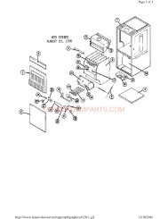
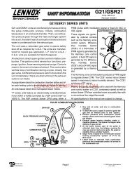
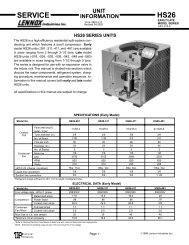
BURNER DETAIL TOP VIEWBURNER BOX ASSEMBLYROLLOUT SWITCH(each side)5/16"ignitorFIGURE 125. Clamshell Heat ExchangerG43UF units use an aluminized steel primary <strong>and</strong> stainlesssteel secondary heat exchanger assembly. Heat istransferred to the air stream from all surfaces of the heatexchanger. The shape of the heat exchanger ensuresmaximum efficiency.The combustion air inducer pulls fresh air through the airintake box. This air is mixed with gas in the burner venturi<strong>and</strong> at the corbel orifices. The gas / air mixture is thenburned at the entrance of each clamshell. Combustiongases are then pulled through the primary <strong>and</strong> secondary heatexchangers <strong>and</strong> exhausted out the exhaust vent pipe.6. Backup Secondary Limit Control (S113)(G43UF−090, 110, 135 only)Backup secondary limit control S113 is a N.C. auto−resetswitch located on the combustion air inducer. S113 acts asa backup to primary limit S10 in the event of an indoor blowerfailure. S113 contacts open when temperature on theCAI reaches 142°.7. Flame Rollout Switches (S47)Flame rollout switches S47 are SPST N.C. high temperaturelimits located on each side of the burner box assembly (seefigure13). S47 is wired to the burner ignition control A92.When either of the switches sense flame rollout (indicatinga blockage in the combustion passages), the flamerollout switch trips, <strong>and</strong> the ignition control immediatelycloses the gas valve. Switch S47 in all G43UF units is factorypreset to open at 250F + 12F (121C + 6.7C) on atemperature rise. All flame rollout switches are <strong>manual</strong> reset.FIGURE 138. Gas Valve (GV1)The G43UF uses a gas valve manufactured by Honeywell orWhite Rodgers (see figure 14 ). The valves are internally redundantto assure safety shut-off. If the gas valve must be replaced,the same type valve must be used.24VAC terminals <strong>and</strong> gas control knob are located ontop of the valve. All terminals on the gas valve are connectedto wires from the ignition control. 24V applied to theterminals opens the valve.Inlet <strong>and</strong> outlet pressure taps are located on the valve. Amanifold adjustment screw is also located on the valve.An LPG changeover kit is available. See table 20. Forunits equipped with the Honeywell VR205 valve, the kitincludes a low pressure switch that must be installed inthe valve as shown in figure 14.The burner box is sealed <strong>and</strong> operates under a negativepressure. A pressure hose is connected from the burnerbox to the gas valve. The gas valve senses the pressure inthe burner box <strong>and</strong> changes gas valve outlet (manifold)pressure based on changes in the burner box pressure.The intent is to compensate for different vent configurationswhich can greatly affect the rate of the unit.IMPORTANTThe White Rodgers 36G gas valve (figure 14) isequipped with pressure posts for measuring supply<strong>and</strong> manifold pressures. The posts provide built−inhose connections <strong>and</strong> have an integral 3/32" Allen−head screw. Rotate the screw counterclockwise onefull turn to permit pressure measurement. Reseat thescrew (rotate one full turn clockwise) after measurementshave been taken to prevent gas leakage.Page 15