g43 service manual - Heating and Air Parts
g43 service manual - Heating and Air Parts
g43 service manual - Heating and Air Parts

You also want an ePaper? Increase the reach of your titles
YUMPU automatically turns print PDFs into web optimized ePapers that Google loves.
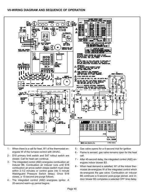
VII−WIRING DIAGRAM AND SEQUENCE OF OPERATION1 − When there is a call for heat, W1 of the thermostat energizesW of the furnace control with 24VAC.2 − S10 primary limit switch <strong>and</strong> S47 rollout switch areclosed. Call for heat can continue.3 − The integrated contol (A92) energizes combustion airinducer B6. Combustion air inducer runs until S18combustion air prove switch closes (switch must closewithin 2−1/2 minutes or control goes into 5 minuteWatchguard Pressure Switch delay). Once S18closes, a 15−second pre−purge follows.4 − The integrated control (A92) energizes ignitor. A20−second warm−up period begins.5 − Gas valve opens for a 4−second trial for ignition6 − Flame is sensed, gas valve remains open for the heatcall.7 − After 45−second delay, the integrated control (A92) energizesindoor blower B3.8 − When heat dem<strong>and</strong> is satisfied, W1 of the indoor thermostatde−energizes W of the integrated control whichde−energizes the gas valve. Combustion air inducerB6 continues a 5−second post−purge period, <strong>and</strong> indoorblower B3 completes a selected OFF time delay.Page 40