g43 service manual - Heating and Air Parts
g43 service manual - Heating and Air Parts
g43 service manual - Heating and Air Parts

Create successful ePaper yourself
Turn your PDF publications into a flip-book with our unique Google optimized e-Paper software.
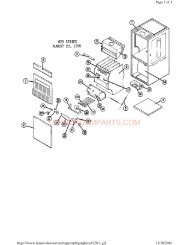
After the 15−second pre−purge period, the ignitor warms upfor 20 seconds during which the gas valve opens at 19 secondsfor a 4−second trial for ignition. The ignitor remainsenergized for the first 3 seconds during the 4 second trial. Ifignition is not proved during the 4−second period, the controlwill try four more times with an inter purge <strong>and</strong> warm−uptime between trials of 35 seconds. After a total of five trialsfor ignition (including the initial trial), the control goes intoWatchguard−Flame Failure mode. After a 60−minute resetperiod, the control will begin the ignition sequence again.The control board has an added feature of ignitor powerregulation to maintain consistent lighting <strong>and</strong> longer ignitorlife under all line voltage conditions.Fan Time ControlThe fan on time of 45 seconds is not adjustable. Fan offtime (time that the blower operates after the heat dem<strong>and</strong>has been satisfied) can be adjusted by moving the jumperto a different setting. The unit is shipped with a factory fanoff setting of 90 seconds. For customized comfort, monitorthe supply air temperature once the heat dem<strong>and</strong> is satisfied.Note the supply air temperature at the instant theblower is de−energized. Adjust the fan−off delay to achievea supply air temperature between 90° − 110° at the instantthe blower is de−energized. (Longer delay times allow forlower air temperature, shorter delay times allow for higherair temperature). See figure 7.Board 100973−01 only has a 45 second fan off delay aftercooling dem<strong>and</strong> is met. This timing is factory set <strong>and</strong> cannotbe adjusted.FAN-OFF TIME ADJUSTMENTTo adjust fan−off timing, reposition jumper across pins toachieve desired setting.FIGURE 7DS1REDDS2GREENIGNITION CONTROL BOARDFIGURE 8C−<strong>Heating</strong> ComponentsCombustion air inducer (B6), primary limit control (S10),SureLight ignitor, burners, flame rollout switch (S47), gasvalve (GV1), combustion air prove switch (S18), <strong>and</strong> clamshellheat exchangers are located in the heating compartment.The heating compartment can be accessed by removingthe burner access panel.1. Ignitor (Figure 9)The SureLight ignitor used on G43UF−1 units, is made ofdurable silicon nitride. The board finds the lowest ignitortemperature which will successfully light the burner, thusincreasing the life of the ignitor. Due to this feature of theboard, voltage cannot be measured. The check ignitor,measure its resistance. A value of 10.9 to 19.7 ohms indicatesa good ignitor.The ignitor used on G43−2 <strong>and</strong> later units use a mini−nitrideignitor made from a proprietary ceramic material. Ignitorlongevity is enhanced by controlling the voltage to the ignitor.The check ignitor, measure its resistance. A value of 50to 450 ohms indicates a good ignitor.Page 13