g43 service manual - Heating and Air Parts
g43 service manual - Heating and Air Parts
g43 service manual - Heating and Air Parts

You also want an ePaper? Increase the reach of your titles
YUMPU automatically turns print PDFs into web optimized ePapers that Google loves.
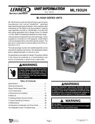
VENT PLUG(Must beglued inplace)PLUGTYPICAL EXHAUST PIPE CONNECTIONS AND CONDENSATE TRAP INSTALLATIONIN UPFLOW DIRECT OR NON-DIRECT VENT APPLICATIONS(Right-H<strong>and</strong> Exit)2”2”2”CONDENSATETRAP(Must be installedon same side asexhaust piping)2”*2−1/2",3", OR4"TRANSITION2"***2"*2−1/2",3", OR4"TRANSITION2”2”2”G43UF−045, 070or 090 with2−1/2", 3", or 4"vent pipeREDUCER(use only if4" pipe isrequired)3"4"3"***2" diameter street elbow provided.**3" diameter reducing elbow provided.***Limit pipe length to 2".G43UF-1 10 with2” vent pipeG43UF−110−1, −2, −3 with2−1/2", 3", OR 4" vent pipeG43UF−135 with3" OR 4" vent pipeFIGURE 19Exhaust PipingNOTE − A 2" diameter street ell is strapped to the blowerCAUTIONdeck of 48C−110 <strong>and</strong> 60C−110 units. Street ell must be Do not discharge exhaust into an existing stack orglued directly into the unit flue collar. See figure 19. A 3" to stack that also serves another gas appliance. If vertical2" reducing ell is strapped to the blower deck of thedischarge through an existing unused stack is re-60D−135 units. The reducing ell must be glued directly intoquired, insert PVC pipe inside the stack until the endis even with the top or outlet end of the metal stack.the unit flue collar.1. Choose the appropriate side for venting. Glue thefield−provided exhaust vent pipe (or provided streetell) to the flue collar. All cement joints should be madeaccording to the specifications outlined in ASTM D2855. Refer to pipe <strong>and</strong> fittings specifications <strong>and</strong> gluingprocedures.IMPORTANTExhaust piping <strong>and</strong> condensate trap must beinstalled on the same side of the unit.2. All horizontal runs of exhaust pipe must slope back towardunit. A minimum of 1/4" (6mm) drop for each 12"(305mm) of horizontal run is m<strong>and</strong>atory for drainage.Horizontal runs of exhaust piping must be supported every5 feet (1.52m) using hangers.NOTE − Exhaust piping should be checked carefully tomake sure there are no sags or low spots.3. On the opposite side of the cabinet, glue the provided2" vent plug into the unused flue collar.4. Route piping to outside of structure. Continue withinstallation following instructions given in piping terminationsection.CAUTIONThe exhaust vent pipe operates under positive pressure<strong>and</strong> must be completely sealed to prevent leakageof combustion products into the living space.Exhaust Pipe Offset12" Min.Upflow ApplicationRooftop Termination12" Min.Upflow ApplicationSide Wall TerminationFIGURE 20Page 23