XC15 Series - Lennox Hvac Manuals
XC15 Series - Lennox Hvac Manuals
XC15 Series - Lennox Hvac Manuals
- No tags were found...

Create successful ePaper yourself
Turn your PDF publications into a flip-book with our unique Google optimized e-Paper software.
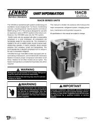
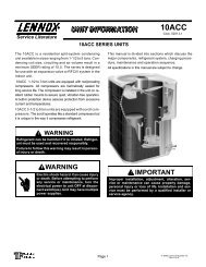
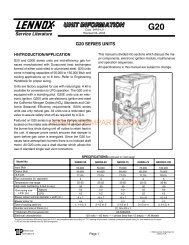
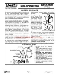
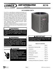
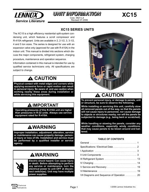
Service LiteratureCorp. 0621−L4Revised 07−2006<strong>XC15</strong><strong>XC15</strong> SERIES UNITSThe <strong>XC15</strong> is a high efficiency residential split−system condensingunit, which features a scroll compressor andR−410A refrigerant. Units are available in 2, 2−1/2, 3, 3−1/2,4 and 5 ton sizes. The series is designed for use with anexpansion valve only (approved for use with R−410A) in theindoor unit. This manual is divided into sections which discussthe major components, refrigerant system, chargingprocedure, maintenance and operation sequence.Information contained in this manual is intended for use byqualified service technicians only. All specifications aresubject to change.CAUTIONPhysical contact with metal edges and corners whileapplying excessive force or rapid motion can resultin personal injury. Be aware of, and use caution whenworking nearby these areas during installation orwhile servicing this equipment.IMPORTANTOperating pressures of this R−410A unit are higherthan pressures in R−22 units. Always use serviceequipment rated for R−410A.WARNINGImproper installation, adjustment, alteration, serviceor maintenance can cause property damage, personalinjury or loss of life. Installation and service mustbe performed by a qualified installer or serviceagency.WARNINGElectric shock hazard. Can cause injuryor death. Before attempting to performany service or maintenance, turn theelectrical power to unit OFF at disconnectswitch(es). Unit may have multiplepower supplies.CAUTIONTo prevent personal injury, or damage to panels, unitor structure, be sure to observe the following:While installing or servicing this unit, carefully stowall removed panels out of the way, so that the panelswill not cause injury to personnel, nor cause damageto objects or structures nearby, nor will the panels besubjected to damage (e.g., being bent or scratched).While handling or stowing the panels, consider anyweather conditions, especially windy conditions,that may cause panels to be blown around and battered.TABLE OF CONTENTSGeneral . . . . . . . . . . . . . . . . . . . . . . . . . . . . . . . . . . . . . . 1Specifications / Electrical Data . . . . . . . . . . . . . . . . . . . 2I Application . . . . . . . . . . . . . . . . . . . . . . . . . . . . . . . . . . 3II Unit Components . . . . . . . . . . . . . . . . . . . . . . . . . . . . 3III Refrigerant System . . . . . . . . . . . . . . . . . . . . . . . . . . 13IV Charging . . . . . . . . . . . . . . . . . . . . . . . . . . . . . . . . . . . 14V Service and Recovery . . . . . . . . . . . . . . . . . . . . . . . . 19VI Maintenance . . . . . . . . . . . . . . . . . . . . . . . . . . . . . . . 19VII Diagrams and Sequence of Operation . . . . . . . . . 20Page 1©2006 <strong>Lennox</strong> Industries Inc.
SPECIFICATIONSGeneralModel No. <strong>XC15</strong>−024 <strong>XC15</strong>−030 <strong>XC15</strong>−036 <strong>XC15</strong>−042 <strong>XC15</strong>−048 <strong>XC15</strong>−060Data Nominal Tonnage 2 2.5 3 3.5 4 5Connections(sweat)Liquid line (o.d.) − in. 3/8 3/8 3/8 3/8 3/8 3/8Suction line (o.d.) − in. 3/4 3/4 3/4 7/8 7/8 1−1/8Refrigerant 1 R−410A charge furnished 8 lbs. 10 oz. 8 lbs. 10 oz. 9 lbs. 2 oz. 9 lbs. 13 oz. 12 lbs. 2 oz. 13 lbs. 0 oz.Outdoor Net face area − sq. ft. Outer coil 20.73 20.73 20.73 20.73 27.21 27.21CoilInner coil 20.08 20.08 20.08 20.08 26.36 26.36OutdoorFanTube diameter − in. 5/16 5/16 5/16 5/16 5/16 5/16No. of rows 2 2 2 2 2 2Fins per inch 22 22 22 22 22 22Diameter − in. 26 26 26 26 26 26No. of blades 3 3 3 3 3 3Motor hp 1/15 1/15 1/12 1/12 1/5 1/5Cfm 2100 2100 2300 2300 3910 3910Rpm 825 825 825 825 825 825Watts 100 100 112 112 212 212Shipping Data − lbs. 1 pkg. 273 274 276 299 346 351ELECTRICAL DATALine voltage data − 60hz208/230V−1ph2 Maximum overcurrent protection (amps) 30 30 35 40 50 603 Minimum circuit ampacity 17.4 18.1 21.5 23.1 28.4 34.1Compressor Rated load amps 13.5 14.1 16.7 17.9 21.8 26.4Outdoor FanMotorLocked rotor amps 58.3 73.0 79.0 112.0 117.0 134.0Power factor 0.97 0.97 0.98 0.93 0.96 0.98Full load amps 0.5 0.5 0.65 0.65 1.1 1.1Locked rotor amps 0.8 0.8 1.1 1.1 2.1 2.1OPTIONAL ACCESSORIES − must be ordered extraCompressor Hard Start Kit 88M91 Compressor Low Ambient Cut−Off 45F08 Compressor Time−Off Control 47J27 Freezestat 3/8 in. tubing 93G35 1/2 in. tubing 39H29 5/8 in. tubing 50A93 Indoor Blower Relay 40K58 Low Ambient Kit 34M72 SignatureStat Home81M27 Comfort ControlRefrigerant L15−41−20 L15−41−40 Line Sets L15−41−30 L15−41−50L15−65−30 L15−65−40L15−65−50Field FabricateTime Delay Relay 58M81 NOTE − Extremes of operating range are plus 10% and minus 5% of line voltage.1 Refrigerant charge sufficient for 15 ft. (4.6 m) length of refrigerant lines.2 HACR type breaker or fuse.3 Refer to National or Canadian Electrical Code manual to determine wire, fuse and disconnect size requirements.Page 2
I−APPLICATIONAll major components (indoor blower and coil) must bematched according to <strong>Lennox</strong> recommendations for thecompressor to be covered under warranty. Refer to the EngineeringHandbook for approved system matchups. Amisapplied system will cause erratic operation and can resultin early compressor failure.CAUTIONIn order to avoid injury, take precaution whenlifting heavy objects.II−Unit ComponentsCONTACTOR<strong>XC15</strong> PARTS ARRANGEMENTOUTDOOR FANRemove the louvered panels as follows:1. Remove 2 screws, allowing the panel to swing openslightly.2. Hold the panel firmly throughout this procedure.Rotate bottom corner of panel away from hinge cornerpost until lower 3 tabs clear the slots (see figure 3, DetailB).3. Move panel down until lip of upper tab clears the topslot in corner post (see figure 3, Detail A).Removing/Installing Louvered PanelsIMPORTANT! Do not allow panels to hang on unit by top tab. Tabis for alignment and not designed to support weight of panel.Panel shown slightly rotatedto allow top tab toexit (or enter) top slotfor removing (or installing)panel.LSOMLIPSCREWHOLESCAPACITORDRIERDetail ADetail BLOW PRESSURESWITCHHIGH PRESSURESWITCHFIGURE 1COMPRESSOR(with sound reduction dome)Removing/Reinstalling PanelsOpen the access panels as described in figure 2.Access PanelDetail CMAINTAIN MINIMUM PANEL ANGLE (AS CLOSE TO PARALLEL WITH THE UNITAS POSSIBLE) WHILE INSTALLING PANEL.ANGLE MAY BE TOOEXTREMEROTATE IN THIS DIRECTION;THEN DOWN TO REMOVE PANELHOLD DOOR FIRMLY TO THE HINGEDSIDE TO MAINTAINFULLY−ENGAGED TABSPREFERRED ANGLEFOR INSTALLATIONRemove 4 screws toremove panel foraccessing compressorand controls.Detail DFIGURE 2FIGURE 3Page 3
ELECTROSTATIC DISCHARGE (ESD)Precautions and ProceduresCAUTIONElectrostatic discharge can affect electroniccomponents. Take precautions during unit installationand service to protect the unit’s electroniccontrols. Precautions will help to avoid controlexposure to electrostatic discharge by puttingthe unit, the control and the technician at thesame electrostatic potential. Neutralize electrostaticcharge by touching hand and all tools on anunpainted unit surface before performing anyservice procedure.A−Scroll Compressor (B1)DISCHARGESUCTIONSCROLL COMPRESSORFIGURE 4The scroll compressor design is simple, efficient and requiresfew moving parts. A cutaway diagram of the scrollcompressor is shown in figure 4.The scrolls are located inthe top of the compressor can and the motor is located justbelow. The oil level is immediately below the motor.The scroll is a simple compression concept centeredaround the unique spiral shape of the scroll and its inherentproperties. Figure 5 shows the basic scroll form. Two identicalscrolls are mated together forming concentric spiralshapes (figure 6 ). One scroll remains stationary, while theother is allowed to orbit" (figure 7). Note that the orbitingscroll does not rotate or turn but merely orbits" the stationaryscroll.SCROLL FORMFIGURE 5DISCHARGEPRESSURECROSS−SECTION OF SCROLLSDISCHARGETIPS SEALED BY ORBITING SCROLLDISCHARGE PRESSUREFIGURE 6STATIONARYSCROLLSUCTIONThe counterclockwise orbiting scroll draws gas into the outercrescent shaped gas pocket created by the two scrolls(figure 7− 1). The centrifugal action of the orbiting scroll sealsoff the flanks of the scrolls (figure 7− 2). As the orbiting motioncontinues, the gas is forced toward the center of thescroll and the gas pocket becomes compressed (figure 7−3).When the compressed gas reaches the center, it is dischargedvertically into a chamber and discharge port in thetop of the compressor. The discharge pressure forcing downon the top scroll helps seal off the upper and lower edges(tips) of the scrolls (figure 6 ). During a single orbit, severalpockets of gas are compressed simultaneously providingsmooth continuous compression.The scroll compressor is tolerant to the effects of liquid return.If liquid enters the scrolls, the orbiting scroll is allowedto separate from the stationary scroll. The liquid is workedtoward the center of the scroll and is discharged. If the compressoris replaced, conventional <strong>Lennox</strong> cleanup practicesmust be used.Due to its efficiency, the scroll compressor is capable ofdrawing a much deeper vacuum than reciprocating compressors.Deep vacuum operation can cause internal fusitearcing resulting in damaged internal parts and will result incompressor failure. This type of damage can be detectedand will result in denial of warranty claims. The scroll compressorcan be used to pump down refrigerant as long asthe pressure is not reduced below 7 psig.NOTE − During operation, the head of a scroll compressormay be hot since it is in constant contact with dischargegas.The scroll compressors in all <strong>XC15</strong> model units are designedfor use with R−410A refrigerant and operation athigh pressures. Compressors are shipped from the factorywith 3MA (32MMMA) P.O.E. oil. See electrical section inthis manual for compressor specifications.Page 4
SUCTIONPOCKETSUCTIONSUCTIONHOW A SCROLL WORKSMOVEMENT OF ORBITSTATIONARY SCROLLORBITINGSCROLLSUCTION1 2FLANKSSEALED BYCENTRIFUGALFORCESUCTIONINTERMEDIATEPRESSUREGASCRESCENTSHAPED GASPOCKET3 4HIGHPRESSUREGASFIGURE 7DISCHARGEPOCKETB−Capacitor (C12)The compressor and fan use a split capacitor. A single dualcapacitor is used for both the fan motor and compressor motor.The two sides (fan and compressor) of the capacitorhave different mfd ratings and may change with each compressor.The capacitor is located in the unit control box.C−Condenser Fan Motor (B4)XP15 units use a single−phase PSC fan motor which requiresaD−High Pressure Switch (S4)IMPORTANTPressure switch settings for R−410A refrigerantwill be significantly higher than units with R−22.A manual-reset, single-pole/single-throw high pressureswitch is located in the liquid line. The switch shuts off thecompressor by de−energizing K1 when liquid line pressurerises above the factory setting. The switch is normally closedand is permanently adjusted to trip (open) at 590 + 10 psi.See figure 1 for switch location.E−Low Pressure Switch (S87)All <strong>XC15</strong> units are equipped with an auto-reset, singlepole/single-throwlow pressure switch is located in the vaporline. This switch shuts off the compressor by de−energizingK1 when vapor line pressure drops below the factorysetting. The switch is closed during normal operating pressureconditions and is permanently adjusted to trip (open)at 40 + 5 psi. The switch automatically resets when vaporline pressure rises above 90 + 5 psi. See figure 1 for switchlocation.F−Contactor (K1)The compressor is energized by a contactor located in thecontrol box. <strong>XC15</strong> units are single−phase with single−pole contactors.See figure 1 for location.DANGERShock HazardRemove all power at disconnect beforeremoving access panel.<strong>XC15</strong> units use single-pole contactors.Potential exists for electricalshock resulting in injury or death.Line voltage exists at all components(even when unit is not in operation).G−Crankcase Heater (HR1) &Thermostat (S40)The compressor in the unit is equipped with a 40 watt, bellyband type crankcase heater. HR1 prevents liquid from accumulatingin the compressor. HR1 is controlled by a thermostatlocated on the liquid line. When liquid line temperaturedrops below 50° F the thermostat closes energizing HR1.The thermostat will open, de−energizing HR1 once liquid linetemperature reaches 70° F .Page 5
H−DrierA filter drier designed for all <strong>XC15</strong> model units is factoryinstalled in the liquid line. The filter drier is designed to removemoisture and foreign matter, which can lead to compressorfailure.Moisture and / or Acid CheckBecause POE oils absorb moisture, the dryness of thesystem must be verified any time the refrigerant systemis exposed to open air. A compressor oil samplemust be taken to determine if excessive moisture has beenintroduced to the oil. Table 1 lists kits available from <strong>Lennox</strong>to check POE oils.If oil sample taken from a system that has been exposed toopen air does not test in the dry color range, the filter drierMUST be replaced.IMPORTANTReplacement filter drier MUST be approved forR−410A refrigerant and POE application.Foreign Matter CheckIt is recommended that a liquid line filter drier be replacedwhen the pressure drop across the filter drier is greaterthan 4 psig.TABLE 1KIT CONTENTS TUBE SHELF LIFE10N46 − Refrigerant Analysis Checkmate−RT70010N45 − Acid Test TubesCheckmate−RT750A (three pack)2 − 3 years @ room temperature. 3+years refrigerated10N44 − Moisture Test Tubes74N40 − Easy Oil Test Tubes74N39 − Acid Test KitCheckmate − RT751 Tubes (threepack)Checkmate − RT752C Tubes (threepack)Sporlan One Shot − TA−16 − 12 months @ room temperature. 2years refrigerated2 − 3 years @ room temperature. 3+years refrigeratedMEASURING FILTER DRIER PRESSURE DROP1− Shut off power to unit. Remove access and service panel.2− Remove high pressure switch from fitting next to filter drier.(A schrader core is located under the high pressure switch).3− Install high pressure gauge hose onto high pressure switch fitting.Secure service panel back in place4− Turn power on to unit and turn room thermostat to call for cooling.5− Record pressure reading on gauge.6− Remove hose from high pressure fitting and install on liquid line valve.7− Read liquid line valve pressure.8− High pressure fitting pressure − liquid line valve pressure = filter drierpressure drop.9− If pressure drop is greater than 4 psig replace filter drier. See figure 9.10− Re−install high pressure switch.Note − Service panel must be in place while unit is operational for an acurate pressure drop reading.FIGURE 8REPLACING FILTER DRIER1− Recover all refrigerant from unit.2− Remove original filter drier.3− Install new filter drier in existing location or alternate location asshown. Proper brazing procedures should be followed.4− Evacuate system. See section IV− part B−.5− Recharge system. See section IV− part C−.alternate locationFIGURE 9Page 6
TABLE 2<strong>Lennox</strong> System Operation Monitor LED Troubleshooting CodesStatus LED Condition Status LED Description Status LED Troubleshooting InformationGreen Power" LED ON Module has power 24VAC control power is present at the module terminal.Green Power" LED Module not powering up Determine/verify that both R and C module terminals are connectedOFFand voltage is present between both terminals.Red Trip" LED ONSystem and compressorcheck out OKThermostat demand signalY1 is present, but compressornot running1 Verify Y terminal is connected to 24VAC at contactor coil.2 Verify voltage at contactor coil falls below 0.5VAC when off.3 Verify 24VAC is present across Y and C when thermostat demandsignal is present; if not present, R and C wires are reversed.1 Compressor protector is open.2 Outdoor unit power disconnect is open.3 Compressor circuit breaker or fuse(s) is open.4 Broken wire or connector is not making contact.5 Low pressure switch open if present in the system.6 Compressor contactor has failed to close.Red Trip" & YellowAlert" LEDs FlashingYellow Alert" FlashCode 1*Yellow Alert" FlashCode 2*Yellow Alert" FlashCode 3*Yellow Alert" FlashCode 4*Yellow Alert" FlashCode 5*Yellow Alert" FlashCode 6*Simultaneous flashing.Long Run Time − Compressoris running extremelylong run cyclesSystem Pressure Trip −Discharge or suction pressureout of limits orcompressor overloadedShort Cycling − Compressoris running only brieflyLocked RotorOpen CircuitOpen Start Circuit − Currentonly in run circuitIndicates that the control circuit voltage is too low for operation.1 Low refrigerant charge.2 Evaporator blower is not running.3 Evaporator coil is frozen.4 Faulty metering device.5 Condenser coil is dirty .6 Liquid line restriction (filter drier blocked if present) .7 Thermostat is malfunctioning .1 High head pressure.2 Condenser coil poor air circulation (dirty, blocked, damaged).3 Condenser fan is not running.4 Return air duct has substantial leakage.5 If low pressure switch is present, see Flash Code 1 information.1 Thermostat demand signal is intermittent.2 Time delay relay or control board is defective.3 If high pressure switch is present, see Flash Code 2 information.4 If low pressure switch is present, see Flash Code 1 information.1 Run capacitor has failed.2 Low line voltage (contact utility if voltage at disconnect is low).3 Excessive liquid refrigerant in the compressor.4 Compressor bearings are seized.1 Outdoor unit power disconnect is open.2 Unit circuit breaker or fuse(s) is open.3 Unit contactor has failed to close.4 High pressure switch is open and requires manual reset.5 Open circuit in compressor supply wiring or connections.6 Unusually long compressor protector reset time due to extreme ambienttemperature.7 Compressor windings are damaged.1 Run capacitor has failed.2 Open circuit in compressor start wiring or connections.3 Compressor start winding is damaged.Yellow Alert" FlashCode 7*Open Run Circuit − Currentonly in start circuit1 Open circuit in compressor start wiring or connections.Compressor start winding is damaged.Yellow Alert" FlashCode 8*Welded Contactor − Compressoralways runs1 Compressor contactor failed to open.Thermostat demand signal not connected to module.Yellow Alert" FlashCode 9*Low Voltage − Control circuit
I−<strong>Lennox</strong> System Operation Monitor (A132)The <strong>Lennox</strong> system operation monitor (LSOM) is a 24 voltpowered module, (see diagnostic module A132 on wiringdiagram and figure 10) wired directly to the indoor unit. TheLSOM is located in the control box and is used to troubleshoot problems in the system. The module has three LED’sfor troubleshooting: GREEN indicates power status, YEL-LOW indicates an abnormal condition and RED indicatesthermostat demand, but compressor not operating. Seetable 2 for troubleshooting codes.The diagnostic indicator detects the most common faultconditions in the air conditioning system. When an abnormalcondition is detected, the module communicates thespecific condition through its ALERT and TRIP lights. Themodule is capable of detecting both mechanical and electricalsystem problems. See figure 10 for the system operationmonitor.<strong>Lennox</strong> System Operation MonitorPOWER LEDY2YLRCALERT LEDTRIP LEDFIGURE 10IMPORTANTDATA OUTPUTCONNECTOR.25" SPADECONNECTOR (5)This monitor does not provide safety protection. Themonitor is a monitoring device only and cannot controlor shut down other devices.LED FunctionsAlert LED (green) − Indicates voltage within the range of19−28VAC is present at the system monitor connections.Alert LED (yellow) − communicates an abnormal systemcondition through a unique Flash Code the alert LEDflashes a number of times consecutively; then pauses;then repeats the process. This consecutive flashing correlatesto a particular abnormal condition.Trip LED (red) − indicates there is a demand signal from thethermostat but no current to the compressor is detected bythe module.Flash code number − corresponds to a number of LEDflashes, followed by a pause, and then repeated.Trip & Alert LEDs flashing simultaneously − indicates thatthe control circuit voltage is too low for operation.Reset ALERT flash code by removing 24VAC power frommonitor. Last ALERT flash code will display for 1 minute aftermonitor is powered on.ThermostatThe <strong>Lennox</strong> system operation monitor (LSOM) requires atwo-stage room thermostat to operate properly.L terminal connectionThe L connection is used to communicatealert codes to the room thermostat. On selected<strong>Lennox</strong> SignatureStat thermostats, a blinkingcheck" LED will display on the room thermostat and onselect White-Rodgers room thermostats, an icon onthe display will flash. Either will flash at the same rateas the LSOM yellow alert LED.NOTE − ROOM THERMOSTAT WITH SERVICE ORCHECK LIGHT FEATURE − The room thermostat mayblink the Check" or Service" LED or it may come onsolid. Confirm fault by observing and interpreting thecode from the LSOM yellow alert LED at the unit.Installation verification-LSOMTo verify correct LSOMinstallation, two functional tests can be performed. Disconnectpower from the compressor and force a thermostatcall for cooling. The red trip LED should turn onindicating a compressor trip as long as 24VAC is measuredat the Y terminal. If the red LED does not functionas described, refer to table 2 to verify the wiring. Disconnectpower from the compressor and 24VAC powerfrom LSOM. Remove the wire from the Y terminal ofLSOM and reapply power to the compressor, allowingthe compressor to run. The yellow alert LED will beginflashing a code 8 indicating a welded contactor. Disconnectpower from the compressor and 24VAC powerfrom the LSOM. While the LSOM is off, reattach thewire to the Y terminal. Reapply power to the compressorand 24VAC power to the LSOM; the yellow alertLED will flash the previous code 8 for one minute andthen turn off. If the yellow LED does not function as described,refer to table 2 to verify the wiring.Resetting alert codesAlert codes can be resetmanually or automatically:Manual reset: Cycle the 24VAC power to LSOM off and on.Automatic reset: After an alert is detected, the LSOMcontinues to monitor the compressor and system.When/if conditions return to normal, the alert code isturned off automatically.Page 8
III−REFRIGERANT SYSTEMWARNINGR−410A refrigerant can be harmful if it is inhaled.R−410A refrigerant must be used and recovered responsibly.Failure to follow this warning may result in personalinjury or death.A−PlumbingField refrigerant piping consists of liquid and vapor linesfrom the outdoor unit (sweat connections) to the indoor coil(flare or sweat connections). Use <strong>Lennox</strong> L15 (sweat, nonflare)series line sets as shown in table 3 or use field-fabricatedrefrigerant lines. Valve sizes are also listed in table 3.TABLE 3Valve SizeRecommended Line Set<strong>XC15</strong> Connections−024−030−036−042−048−060LiquidLine3/8 in.(10 mm)3/8 in.(10 mm)3/8 in.(10 mm)VaporLine7/8 in.(22 mm)7/8 in.(22 mm1−1/8 in.(29 mm)LiquidLine3/8 in.(10 mm)3/8 in.(10 mm)3/8 in.(10 mm)VaporLine7/8 in.(22 mm)7/8 in.(22 mm)1−1/8 in.(29 mm)L15Line SetsL15−6515 ft. − 50 ft.(4.6 m − 15 m)L15−6515 ft. − 50 ft.(4.6 m − 15 m)FieldFabricatedNOTE − When installing refrigerant lines, refer to <strong>Lennox</strong>Technical Support Product Applications for assistance. Inaddition, be sure to consider the following points:Select line set diameters from table 3 to ensure that oil returnsto the compressor.Units are designed for line sets of up to fifty feet (15 m); forlonger line sets, consult piping guidelines.Size vertical vapor riser to maintain minimum velocity atminimum capacity.B−Service ValvesThe liquid line and vapor line service valves (figures 11 and12) and gauge ports are used for leak testing, evacuating,charging and checking charge. See table 4 for torque requirements.Each valve is equipped with a service port which has a factory−installedSchrader valve. A service port cap protectsthe Schrader valve from contamination and serves as theprimary leak seal.PartTABLE 4Recommended TorqueService valve cap 8 ft.− lb. 11 NMSheet metal screws 16 in.− lb. 2 NMMachine screws #10 28 in.− lb. 3 NMCompressor bolts 90 in.− lb. 10 NMGauge port seal cap 8 ft.− lb. 11 NMTo Access Schrader Port:1 − Remove service port cap with an adjustable wrench.2 − Connect gauge to the service port.3 − When testing is complete, replace service port cap.Tighten finger tight, then an additional 1/6 turn.To Open Service Valve:1 − Remove the stem cap with an adjustable wrench.2 − Use a service wrench with a hex−head extension toback the stem out counterclockwise as far as it will go.NOTE − Use a 3/16" hex head extension for 3/8" linesizes.3 − Replace the stem cap. Tighten finger tight, then tightenan additional 1/6 turn.Page 9
To Close Service Valve:1 − Remove the stem cap with an adjustable wrench.2 − Use a service wrench with a hex−head extension toturn the stem clockwise to seat the valve. Tighten thestem firmly.NOTE − Use a 3/16" hex head extension for 3/8" linesizes.3 − Replace the stem cap. Tighten finger tight, then tightenan additional 1/6 turn.serviceport capinsert hexwrench herestem capserviceport capvalvecorestemcapLiquid Line Service Valve(Valve Closed)service portto outdoor coilLiquid Line Service Valve(Valve Open)service portinsert hexwrench heretoindoor coiltoindoor coilService Port Is Open to outdoor coilTo Line Set When Valve IsClosed (Front Seated)(valve front seated)FIGURE 11Vapor Line Ball Valve – All UnitsVapor line service valves function the same way as the othervalves, the difference is in the construction. Thesevalves are not rebuildable. If a valve has failed, you mustreplace it. A ball valve is illustrated in figure 12.The ball valve is equipped with a service port with a factory−installed Schrader valve. A service port cap protects theSchrader valve from contamination and assures a leak−free seal.Ball Valve (Valve Closed)Use Adjustable WrenchTo open: rotate Stem Clockwise 90°.To close: rotate Stem Counter-clockwise 90°.Use Adjustable WrenchTo close: rotate StemCounter-clockwise 90°.To open: rotate StemClockwise 90°.SERVICEPORTSCHRADERVALVESERVICEPORT CAPIV−CHARGINGTo indoor coilTo outdoor coilFIGURE 12IMPORTANTBALL(Shownclosed)STEMSTEMCAPThe Clean Air Act of 1990 bans the intentional ventingof (CFC’s and HFC’s) as of July 1, 1992. Approvedmethods of recovery, recycling or reclaiming mustbe followed. Fines and/or incarceration my be leviedfor noncompliance.Units are factory charged with the amount of R−410A refrigerantindicated on the unit rating plate. This charge isbased on a matching indoor coil and outdoor coil with 15 ft.(4.6m) line set. For varying lengths of line set, refer to table5 for refrigerant charge adjustment.TABLE 5Liquid Line SetDiameter3/8 in.(9.5 mm)Oz. per 5 ft. (grams per 1.5m) adjustfrom 15 ft. (4.6 m) line set*3 ounces per 5 feet(85 g per 1.5 m)*If line length is greater than 15 ft. (4.6 m), add this amount.If line length is less than 15 ft. (4.6 m), subtract this amount.A−Leak TestingAfter the line set has been connected to the indoor andoutdoor units, check the line set connections and indoorunit for leaks.Page 10
WARNINGRefrigerant can be harmful if it is inhaled. Refrigerantmust be used and recovered responsibly.Failure to follow this warning may result in personalinjury or death.WARNINGFire, Explosion and Personal Safety Hazard.Failure to follow this warning could result in damage,personal injury or death.Never use oxygen to pressurize or purge refrigerationlines. Oxygen when exposed to a spark or openflame can cause damage by fire and or an explosion,that could result in personal injury or death.WARNINGDanger of explosion. Can cause equipment damage,injury or death. When using a high pressure gassuch as dry nitrogen to pressurize a refrigeration orair conditioning system, use a regulator that cancontrol the pressure down to 1 or 2 psig (6.9 to 13.8kPa).Using an Electronic Leak Detector1 − Connect the high pressure hose of the manifold gaugeset to the vapor valve service port. (Normally, the highpressure hose is connected to the liquid line port, however,connecting it to the vapor port helps to protect themanifold gauge set from damage caused by high pressure.)2 − With both manifold valves closed, connect the cylinderof R−410A refrigerant. Open the valve on the R−410Acylinder (vapor only).3 − Open the high pressure side of the manifold to allowR−410A into the line set and indoor unit. Weigh in atrace amount of R−410A. [A trace amount is a maximumof 2 ounces (57 g) refrigerant or 3 pounds (31kPa) pressure.] Close the valve on the R−410A cylinderand the valve on the high pressure side of the manifoldgauge set. Disconnect R−410A cylinder.4 − Connect a cylinder of nitrogen with a pressure regulatingvalve to the center port of the manifold gauge set.5 − Adjust nitrogen pressure to 150 psig (1034 kPa). Openthe valve on the high side of the manifold gauge set inorder to pressurize the line set and the indoor coil.6 − After a few minutes, open a refrigerant port to checkthat an adequate amount of refrigerant has been addedfor detection (refrigerant requirements will varywith line lengths). Check all joints for leaks. Purge nitrogenand R−410A mixture. Correct any leaks and recheck.B−Evacuating the SystemEvacuating the system of noncondensables is critical forproper operation of the unit. Noncondensables are definedas any gas that will not condense under temperatures andpressures present during operation of an air conditioningsystem. Noncondensables and water vapor combine withrefrigerant to produce substances that corrode copper pipingand compressor parts.NOTE − This evacuation process is adequate for a newinstallation with clean and dry lines. If excessive moistureis present, the evacuation process may be requiredmore than once.IMPORTANTUse a thermocouple or thermistor electronic vacuumgauge that is calibrated in microns. Use an instrumentthat reads from 50 microns to at least 10,000 microns.1 − Connect manifold gauge set to the service valve ports : low pressure gauge to vapor line service valve high pressure gauge to liquid line service valve2 − Connect micron gauge.3 − Connect the vacuum pump (with vacuum gauge) to thecenter port of the manifold gauge set.4 − Open both manifold valves and start the vacuumpump.5 − Evacuate the line set and indoor unit to an absolutepressure of 23,000 microns (29.01 inches of mercury).During the early stages of evacuation, it is desirableto close the manifold gauge valve at least once todetermine if there is a rapid rise in absolute pressure.A rapid rise in pressure indicates a relatively large leak.If this occurs, repeat the leak testing procedure.NOTE − The term absolute pressure means the totalactual pressure within a given volume or system,above the absolute zero of pressure. Absolute pressurein a vacuum is equal to atmospheric pressure minusvacuum pressure.6 − When the absolute pressure reaches 23,000 microns(29.01 inches of mercury), close the manifold gaugevalves, turn off the vacuum pump and disconnect themanifold gauge center port hose from vacuum pump.Attach the manifold center port hose to a nitrogen cylinderwith pressure regulator set to 150 psig (1034 kPa)and purge the hose. Open the manifold gauge valvesto break the vacuum in the line set and indoor unit.Close the manifold gauge valves.Page 11
CAUTIONDanger of Equipment Damage.Avoid deep vacuum operation. Do not use compressorsto evacuate a system.Extremely low vacuums can cause internal arcingand compressor failure.Damage caused by deep vacuum operation will voidwarranty.7 − Shut off the nitrogen cylinder and remove the manifoldgauge hose from the cylinder. Open the manifoldgauge valves to release the nitrogen from the line setand indoor unit.8 − Reconnect the manifold gauge to the vacuum pump,turn the pump on, and continue to evacuate the line setand indoor unit until the absolute pressure does notrise above 500 microns (29.9 inches of mercury) withina 20−minute period after shutting off the vacuum pumpand closing the manifold gauge valves.9 − When the absolute pressure requirement above hasbeen met, disconnect the manifold hose from the vacuumpump and connect it to an upright cylinder of R−410Arefrigerant. Open the manifold gauge valves to breakthe vacuum from 1 to 2 psig positive pressure in the lineset and indoor unit. Close manifold gauge valves andshut off the R−410A cylinder and remove the manifoldgauge set.C−ChargingCharge Using Weigh-in MethodOutdoor Temperature< 65ºF (18ºC)If the system is void of refrigerant, or if the outdoor ambienttemperature is cool, first, locate and repair any leaks andthen weigh in the refrigerant charge into the unit.1. Recover the refrigerant from the unit.2. Conduct leak check; evacuate as previously outlined.3. Weigh in the unit nameplate charge. If weighing facilitiesare not available or if charging the unit during warmweather, use one of the following procedures.Charge Using the Approach MethodOutdoorTemp. >65ºF (18ºC)The following procedure is intended as a general guide andis for use on expansion valve systems only. For best results,outdoor temperature should be 70°F (21°C) to 80°F (26°C).Monitor system pressures while charging.1. Record outdoor ambient temperature using a digitalthermometer.2. Attach high pressure gauge set and operate unit forseveral minutes to allow system pressures to stabilize.3. Compare stabilized pressures with those provided intable 7, Normal Operating Pressures." Minor variationsin these pressures may be expected due to differencesin installations. Significant differences couldmean that the system is not properly charged or that aproblem exists with some component in the system.Pressures higher than those listed indicate that thesystem is overcharged. Pressures lower than thoselisted indicate that the system is undercharged. Continueto check adjusted charge using approach values.4. Use the same digital thermometer you used to checkthe outdoor ambient temperature to check the liquidline temperature.5. The difference between the ambient and liquid temperaturesshould match values given in table 6. If the valuesdo not agree with the those in table 6, add refrigerantto lower the approach temperature, or recover refrigerantfrom the system to increase the approachtemperature.TABLE 6<strong>XC15</strong> Approach Values Liquid Line Temperature Outdoor Temperature= Approach TemperatureModel −024 −030 −036 −042 −048 −060°F(°C)*10(5.6)12(6.7)11(6.1)13(7.2)6(3.3)10(5.6)NOTE − For best results, use the same electronic thermometer tocheck both outdoor-ambient and liquid-line temperatures.*F: +/−1.0°; C: +/−0.5°NOTES −R−410A refrigerant cylinders are rose−colored. Refrigerantshould be added through the vapor valve in the liquidstate.Certain R−410A cylinders are identified as being equippedwith a dip tube. These allow liquid refrigerant to bedrawn from the bottom of the cylinder without invertingthe cylinder. DO NOT turn this type cylinder upside−down to draw refrigerant.Page 12
TABLE 7<strong>XC15</strong> Normal Operating Pressures In psig (liquid +/− 10 and vapor+/− 5 PSIG)*Model −024 −030 −036 −042 −048 −060F (C)** Liquid Suction Liquid Suction Liquid Suction Liquid Suction Liquid Suction Liquid Suction65 (18.3) 239 135 246 135 245 132 260 132 224 129 242 13170 (21.1) 255 136 266 136 264 133 282 133 241 130 262 13275 (23.9) 274 137 285 138 285 135 302 134 259 131 282 13480 (26.7) 293 138 306 139 306 137 325 135 279 133 303 13585 (29.4) 317 139 328 140 328 137 347 136 301 134 326 13690 (32.2) 339 140 350 141 352 139 370 137 323 135 349 13795 (35.0) 362 141 374 142 375 140 395 138 347 137 372 138100 (37.8) 387 142 399 143 400 141 421 139 372 138 397 140105 (40.6) 415 144 423 144 425 141 446 141 397 140 422 141110 (43.3) 440 145 450 145 452 143 475 142 422 141 448 143115 (46.1) 469 146 477 146 476 144 504 144 449 143 475 146* These are typical pressures only. Indoor match up, indoor air quality, and indoor load will cause the pressures to vary.** Temperature of air entering outdoor coil.Charge Using Subcooling MethodOutdoor Temperature> 65ºF (18ºC)Use the following method to obtain accurate subcoolingvalues. Compare the measured subcooling value to thevalues given in table 8.Table 8<strong>XC15</strong> Subcooling Values(psig ) Saturation Temperature Liquid Line Temperature= Subcooling ValueModel −024 −030 −036 −042 −048 −060°F(°C)*4(2.2)4(2.2)6(3.3)7(3.9)6(3.3)7(3.9)NOTE − For best results, use the same electronic thermometer tocheck both outdoor-ambient and liquid-line temperatures.*F: +/−1.0°; C: +/−0.5°1. With the manifold gauge hose still on the liquid serviceport and the unit operating stably, use a digital thermometerto record the liquid line temperature in thespace provided in table 8, and at the same time, recordthe liquid line pressure reading in the (psig___)" spacein the table.2. Use a temperature/pressure chart for R−410A (table 9)to determine the saturation temperature for the liquidline pressure reading and record that in the space providedin table 8.3. Subtract the liquid line temperature from the saturationtemperature (according to the chart) to determine thesubcooling value.4. Compare subcooling value with those in table 8. If subcoolingis greater than shown, recover some refrigerant;if less than shown, add some refrigerant.Charge using Subcooling MethodOutdoor Temperature< 65ºF (18ºC)When the outdoor ambient temperature is below 65°F(18°C), use the subcooling method to charge the unit. Itmay be necessary to restrict the air flow through the outdoorcoil to achieve pressures in the 325−375 psig(2240−2585 kPa) range. These higher pressures are necessaryfor checking the charge. Block equal sections of airintake panels and move obstructions sideways until the liquidpressure is in the 325−375 psig (2240−2585 kPa) range.See figure 13.Blocking Outdoor CoilFIGURE 13*Outdoor coil should be blocked oneside at a time with cardboard or plasticsheet until proper testing pressures arereached.cardboard or plastic sheet*Four−sided unit shown.Page 13
TABLE 9R−410A Temperature/Pressure ChartR−410A Temperature (°F) − Pressure (Psig)°F Psig °F Psig °F Psig °F Psig32 100.8 63 178.5 94 290.8 125 445.933 102.9 64 181.6 95 295.1 126 451.834 105.0 65 184.3 96 299.4 127 457.635 107.1 66 187.7 97 303.8 128 463.536 109.2 67 190.9 98 308.2 129 469.537 111.4 68 194.1 99 312.7 130 475.638 113.6 69 197.3 100 317.2 131 481.639 115.8 70 200.6 101 321.8 132 487.840 118.0 71 203.9 102 326.4 133 494.041 120.3 72 207.2 103 331.0 134 500.242 122.6 73 210.6 104 335.7 135 506.543 125.0 74 214.0 105 340.5 136 512.944 127.3 75 217.4 106 345.3 137 519.345 129.7 76 220.9 107 350.1 138 525.846 132.2 77 224.4 108 355.0 139 532.447 134.6 78 228.0 109 360.0 140 539.048 137.1 79 231.6 110 365.0 141 545.649 139.6 80 235.3 111 370.0 142 552.350 142.2 81 239.0 112 375.1 143 559.151 144.8 82 242.7 113 380.2 144 565.952 147.4 83 246.5 114 385.4 145 572.853 150.1 84 250.3 115 390.7 146 579.854 152.8 85 254.1 116 396.0 147 586.855 155.5 86 258.0 117 401.3 148 593.856 158.2 87 262.0 118 406.7 149 601.057 161.0 88 266.0 119 412.2 150 608.158 163.9 89 270.0 120 417.7 151 615.459 166.7 90 274.1 121 423.2 152 622.760 169.6 91 278.2 122 428.8 153 630.161 172.6 92 282.3 123 434.5 154 637.562 175.4 93 286.5 124 440.2 155 645.0V−SERVICE AND RECOVERYWARNINGPolyol ester (POE) oils used with R−410A refrigerantabsorb moisture very quickly. It is very importantthat the refrigerant system be kept closed asmuch as possible. DO NOT remove line set caps orservice valve stub caps until you are ready to makeconnections.IMPORTANTUSE RECOVERY MACHINE RATED FOR R−410AREFRIGERANT.If the <strong>XC15</strong> system must be opened for any kind of service,such as compressor or filter drier replacement, you musttake extra precautions to prevent moisture from enteringthe system. The following steps will help to minimize theamount of moisture that enters the system during recoveryof R−410A.1 − Use a regulator−equipped nitrogen cylinder to breakthe system vacuum. Do not exceed 5 psi. The dry nitrogenwill fill the system, purging any moisture.2 − Remove the faulty component and quickly seal thesystem (using tape or some other means) to preventadditional moisture from entering the system.3 − Do not remove the tape until you are ready to installnew component. Quickly install the replacement component.4 − Evacuate the system to remove any moisture and othernon−condensables.The <strong>XC15</strong> system MUST be checked for moisture anytimethe system is opened.Any moisture not absorbed by the polyol ester oil can be removedby triple evacuation. Moisture that has been absorbedby the compressor oil can be removed by replacingthe filter drier.IMPORTANTEvacuation of system only will not remove moisturefrom oil. Filter drier must be replaced to eliminatemoisture from POE oil.Page 14
VI−SR1 SOUND REDUCTIONFigure 14 identifies the sound reduction components andshows the correct procedure for assembling the sound reductioncover.LEFTTOPCAPMIDDLE CABLE TIELEFTSIDECOVERSUCTIONGROMMETTOP CABLE TIEBASEBOTTOM CABLE TIERIGHT TOPCAPRIGHTSIDECOVERDISCHARGEGROMMET1. Put SR1 base on unit base pan.2. Install compressor on base.3. Cover SR1 base with wet rags to protect againstany brazing material.4. Braze suction tube.5. Braze discharge tube.6. Cool connections to ambient temperature.7. Perform leak check.8. Install suction grommet.9. Install SR1 left and right side covers.10. Fasten 60" bottom cable tie.11. Install discharge grommet.12. Install top caps.13. Fasten 36" top cable tie.14. Fasten 36" middle cable tie.VII−MAINTENANCEWARNINGElectric shock hazard. Can cause injuryor death. Before attempting to performany service or maintenance, turnthe electrical power to unit OFF at disconnectswitch(es). Unit may havemultiple power supplies.See section II− for removing access panels. Maintenanceand service must be performed by a qualified installer orservice agency. At the beginning of each cooling season,the system should be checked as follows:FIGURE 141 − Clean and inspect the outdoor coil. The coil may beflushed with a water hose. Ensure the power is turnedoff before you clean the coil.2 − Condenser fan motor is prelubricated and sealed. Nofurther lubrication is needed.3 − Visually inspect connecting lines and coils for evidenceof oil leaks.4 − Check wiring for loose connections.5 − Check for correct voltage at unit (unit operating).6 − Check amp−draw on condenser fan motor.NOTE − If owner complains of insufficient cooling, theunit should be gauged and refrigerant chargechecked. Refer to section on refrigerant charging inthis instruction.Page 15
VIII−DIAGRAMS / OPERATING SEQUENCEA− Unit Diagram <strong>XC15</strong>−024/060−1PSequence of OperationCooling Demand1 Cooling demand initiates at Y1 in the thermostat.2 Voltage from terminal Y passes through the TOC (if used)through S4 high pressure switch, energizes K1 compressorcontactor, passes through S87 low pressure switch and returnsto common side of the 24VAC power.3 K1 closes energizing compressor B1 and outdoor fan B4.Outdoor fan motor is energized.End of Cooling Demand4 Cooling demand is satisfied. Terminal Y1 is de−energized.5 Contactor K1 is de−energized.6 K1−1 opens, compressor B1 and outdoor fan B4 are de−energized.Page 16