CB26 - Heating and Air Parts
CB26 - Heating and Air Parts
CB26 - Heating and Air Parts

Create successful ePaper yourself
Turn your PDF publications into a flip-book with our unique Google optimized e-Paper software.
Service Literature<br />
Corp. 0527−L10<br />
Revised May 2011<br />
<strong>CB26</strong>UH <strong>and</strong> CBX26UH Series<br />
Table of Contents<br />
<strong>CB26</strong>UH<br />
CBX26UH<br />
Model Number Information . . . . . . . . . . . . . . . . . . . 2<br />
Specifications / Electrical Data . . . . . . . . . . . . . . . . 3<br />
Blower Data . . . . . . . . . . . . . . . . . . . . . . . . . . . . . . . . 5<br />
I Application . . . . . . . . . . . . . . . . . . . . . . . . . . . . . . . . 9<br />
II Unit Components . . . . . . . . . . . . . . . . . . . . . . . . . . 9<br />
III Optional Electric Heat . . . . . . . . . . . . . . . . . . . . 10<br />
IV Configuration Modification . . . . . . . . . . . . . . . . 16<br />
V Start Up . . . . . . . . . . . . . . . . . . . . . . . . . . . . . . . . . 18<br />
VI Typical Operating Characteristics . . . . . . . . . . 19<br />
WARNING<br />
Improper installation, adjustment, alteration, service<br />
or maintenance can cause personal injury, loss of<br />
life, or damage to property.<br />
Installation <strong>and</strong> service must be performed by a<br />
licensed professional installer (or equivalent) or a<br />
service agency.<br />
CAUTION<br />
Physical contact with metal edges <strong>and</strong> corners while<br />
applying excessive force or rapid motion can result<br />
in personal injury. Be aware of, <strong>and</strong> use caution when<br />
working near these areas during installation or while<br />
servicing this equipment.<br />
IMPORTANT<br />
The Clean <strong>Air</strong> Act of 1990 bans the intentional venting<br />
of refrigerant (CFCs, HCFCs <strong>and</strong> HFCs) as of July 1,<br />
1992. Approved methods of recovery, recycling or<br />
reclaiming must be followed. Fines <strong>and</strong>/or<br />
incarceration may be levied for noncompliance.<br />
VII Maintenance . . . . . . . . . . . . . . . . . . . . . . . . . . . . 19<br />
VIII Wiring Diagrams . . . . . . . . . . . . . . . . . . . . . . . . 20<br />
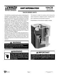
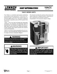
The <strong>CB26</strong>UH, <strong>and</strong> CBX26UH are high efficiency blower coils.<br />
Several models are available in sizes ranging from 1-1/2<br />
through 5 tons (5.3 through 17.6 kW). The CBX26UH is<br />
designed for HFC−410A refrigerant <strong>and</strong> the <strong>CB26</strong>UH is<br />
designed for HCFC−22 refrigerant. The units are up flow /<br />
horizontal that can be field converted to down flow applications.<br />
The units come with a factory installed check <strong>and</strong> expansion<br />
valve for cooling or heat pump applications.<br />
<strong>CB26</strong>UH <strong>and</strong> CBX26UH series units are designed to be<br />
matched with the 13SEER air conditioner <strong>and</strong> heat pump line,<br />
but can be matched with other air conditioners or heat pumps<br />
as noted in the rating information. See Engineering H<strong>and</strong>book.<br />
Electric heat, in several kW sizes, can be field installed in the<br />
<strong>CB26</strong>UH <strong>and</strong> CBX26UH cabinets.<br />
Information contained in this manual is intended for use by<br />
experienced HVAC service technicians only. All specifications<br />
are subject to change. Procedures outlined in this manual are<br />
presented as a recommendation only <strong>and</strong> do not supersede or<br />
replace local or state codes.<br />
Page 1<br />
2011 Lennox Industries Inc.<br />
Litho U.S.A.
MODEL NUMBER IDENTIFICATION<br />
Unit Type<br />
CB = <strong>Air</strong> H<strong>and</strong>ler<br />
Series<br />
Configuration<br />
UH = Up−Flow / Horizontal<br />
MODEL NUMBER IDENTIFICATION<br />
CB 26 UH − 030 − R − 230 − 1<br />
Metering Device<br />
R = Factory Installed RFCIV<br />
(No R = TXV)<br />
Nominal Cooling Capacity<br />
018 = 1.5 tons 042 = 3.5 tons<br />
024 = 2 tons<br />
048 = 4 tons<br />
030 = 2.5 tons 060 = 5 tons<br />
036 = 3 tons<br />
CB X 26 UH − 030 − 230 − 1<br />
Minor Revision Number<br />
Voltage<br />
230 = 208/230V−1phase−60hz<br />
Unit Type<br />
CB − <strong>Air</strong> H<strong>and</strong>ler<br />
Refrigerant Type<br />
X = HFC−410A<br />
Series<br />
Configuration<br />
UH = Up−Flow / Horizontal<br />
Nominal Cooling Capacity<br />
018 = 1.5 tons<br />
024 = 2 tons<br />
030 = 2.5 tons<br />
036 = 3 tons<br />
037 = 3 tons<br />
042 = 3.5 tons<br />
048 = 4 tons<br />
060 = 5 tons<br />
Minor Revision Number<br />
Voltage<br />
230 = 208/230V−1 phase−60hz<br />
Page 2
SPECIFICATIONS — CB(X)26UH−0XX−(R)−230−01 Build<br />
General<br />
Data<br />
Model Number CBX26UH−018 CBX26UH−024 CBX26UH−030 CBX26UH−036<br />
Nominal tonnage 1.5 2 2.5 3<br />
Connections Suction/Vapor line (o.d.) − in. (mm) sweat 3/4 (19) 3/4 (19) 7/8 (22.2) 7/8 (22.2)<br />
Liquid line (o.d.) − in. (mm) sweat 3/8 (9.5) 3/8 (9.5) 3/8 (9.5) 3/8 (9.5)<br />
Condensate − in. (mm) fpt (2) 3/4 (19) (2) 3/4 (19) (2) 3/4 (19) (2) 3/4 (19)<br />
Indoor<br />
Coil<br />
Net face area − ft. 2 (m 2 ) 4 (0.37) 4 (0.37) 4.88 (0.45) 4.88 (0.45)<br />
Tube outside diameter − in. (mm) 3/8 (9.5) 3/8 (9.5) 3/8 (9.5) 3/8 (9.5)<br />
Number of rows 3 3 3 3<br />
Fins per inch (fins per m) 15 (591) 14 (551) 14 (551) 14 (551)<br />
Blower Wheel nominal diameter x width − in. (mm) 10 x 6<br />
(254 x 152)<br />
1 Filters Size of filter − in. (mm) 15 x 20 x 1<br />
(406 x 508 x 25)<br />
ELECTRICAL DATA<br />
10 x 6<br />
(254 x 152)<br />
11 x 8<br />
(279 x 203)<br />
11 x 8<br />
(279 x 203)<br />
Blower motor output − hp (W) 1/4 (187) 1/4 (187) 1/4 (187) 1/3 (249)<br />
15 x 20 x 1 18 x 20 x 1<br />
(406 x 508 x 25) (457 x 508 x 25)<br />
18 x 20 x 1<br />
(457 x 508 x 25)<br />
Voltage − 1 phase (60 hz) 208/240V 208/240V 208/240V 208/240V<br />
2 Maximum overcurrent protection (unit only) 15 15 15 15<br />
3 Minimum circuit ampacity (unit only) 1.5 1.5 1.6 2.0<br />
Shipping Data −1 package − lbs. (kg) 129 (58) 131 (59) 148 (67) 148 (67)<br />
SPECIFICATIONS — CB(X)26UH−0XX−(R)−230−01 Build<br />
General<br />
Data<br />
Model Number CBX26UH−037 CBX26UH−042 CBX26UH−048 CBX26UH−060<br />
Nominal tonnage 3 3.5 4 5<br />
Connections Suction/Vapor line (o.d.) − in. (mm) sweat 7/8 (22.2) 7/8 (22.2) 7/8 (22.2) 7/8 (22.2)<br />
Liquid line (o.d.) − in. (mm) sweat 3/8 (9.5) 3/8 (9.5) 3/8 (9.5) 3/8 (9.5)<br />
Condensate − in. (mm) fpt (2) 3/4 (19) (2) 3/4 (19) (2) 3/4 (19) (2) 3/4 (19)<br />
Indoor<br />
Coil<br />
Net face area − ft. 2 (m 2 ) 5.84 (0.54) 5.84 (0.54) 7.58 (0.70) 8.76 (0.81)<br />
Tube outside diameter − in. (mm) 3/8 (9.5) 3/8 (9.5) 3/8 (9.5) 3/8 (9.5)<br />
Number of rows 3 3 3 3<br />
Fins per inch (fins per m) 14 (551) 14 (551) 14 (551) 14 (551)<br />
Blower Wheel nominal diameter x width − in. (mm) 11 x 8<br />
(279 x 203)<br />
11 x 8<br />
(279 x 203)<br />
11 x 8<br />
(279 x 203)<br />
11−1/2 x 9<br />
(292 x 229)<br />
Blower motor output − hp (W) 1/3 (249) 1/3 (249) 1/2 (373) 1/2 (373)<br />
1 Filters Size of filter − in. (mm) 18 x 25 x 1<br />
(457 x 635 x 25)<br />
18 x 25 x 1<br />
(457 x 635 x 25)<br />
18 x 25 x 1<br />
(457 x 635 x 25)<br />
18 x 25 x 1<br />
(457 x 635 x 25)<br />
ELECTRICAL DATA<br />
Voltage − 1 phase (60 hz) 208/240V 208/240V 208/240V 208/240V<br />
2 Maximum overcurrent protection (unit only) 15 15 15 15<br />
3 Minimum circuit ampacity (unit only) 1.8 2.0 2.6 4.1<br />
Shipping Data −1 package − lbs. (kg) 172 (78) 172 (78) 177 (80) 190 (86)<br />
1 Filter is not furnished <strong>and</strong> must be field supplied.<br />
2 HACR type circuit breaker or fuse.<br />
3 Refer to National or Canadian Electrical Code manual to determine wire, fuse <strong>and</strong> disconnect size requirements. Use wires suitable for at least 167F (75C).<br />
Page 3
SPECIFICATIONS — CB(X)26UH−0XX−(R)−230−02 Build 4<br />
General<br />
Data<br />
Model Number CBX26UH−042 CBX26UH−048 CBX26UH−060<br />
Nominal tonnage 3.5 4 5<br />
Connections Suction/Vapor line (o.d.) − in. (mm) sweat 7/8 (22.2) 7/8 (22.2) 7/8 (22.2)<br />
Liquid line (o.d.) − in. (mm) sweat 3/8 (9.5) 3/8 (9.5) 3/8 (9.5)<br />
Condensate − in. (mm) fpt (2) 3/4 (19) (2) 3/4 (19) (2) 3/4 (19)<br />
Indoor<br />
Coil<br />
Net face area − ft. 2 (m 2 ) 5.84 (0.54) 7.58 (0.70) 8.76 (0.81)<br />
Tube outside diameter − in. (mm) 3/8 (9.5) 3/8 (9.5) 3/8 (9.5)<br />
Number of rows 3 3 3<br />
Fins per inch (fins per m) 14 (551) 14 (551) 14 (551)<br />
Blower Wheel nominal diameter x width − in. (mm) 11 x 8<br />
(279 x 203)<br />
11−1/2 x 9<br />
(279 x 203)<br />
12 x 9<br />
(292 x 229)<br />
Blower motor output − hp (W) 1/2 (373) 1/2 (373) 1/2 (373)<br />
1 Filters Size of filter − in. (mm) 18 x 25 x 1<br />
(457 x 635 x 25)<br />
18 x 25 x 1<br />
(457 x 635 x 25)<br />
18 x 25 x 1<br />
(457 x 635 x 25)<br />
Shipping Data −1 package − lbs. (kg) 172 (78) 177 (80) 190 (86)<br />
ELECTRICAL DATA<br />
Voltage − 1 phase (60 hz) 208/240V 208/240V 208/240V<br />
2 Maximum overcurrent protection (unit only) 15 15 15<br />
3 Minimum circuit ampacity (unit only) 2.0 2.6 4.1<br />
1 Filter is not furnished <strong>and</strong> must be field supplied.<br />
2 HACR type circuit breaker or fuse.<br />
3 Refer to National or Canadian Electrical Code manual to determine wire, fuse <strong>and</strong> disconnect size requirements. Use wires suitable for at least 167F (75C).<br />
4 Only the 3.5, 4 <strong>and</strong> 5 ton units had specifications changed for −02 build. Use previous specification section for all other sizes.<br />
Page 4
BLOWER DATA<br />
The following tables pertain to the −01 build CB(X)26UH−0XX−230−01:<br />
CB(X)26UH−018−230−01 BLOWER PERFORMANCE<br />
<strong>Air</strong> Volume at<br />
External Static<br />
Specific Blower Taps<br />
Pressure<br />
High<br />
Low<br />
in. w.g. Pa cfm L/s cfm L/s<br />
.10 25 1020 460 755 340<br />
.20 50 960 435 715 325<br />
.30 75 885 400 675 305<br />
.40 100 800 365 625 285<br />
.50 125 690 315 570 260<br />
.60 150 525 250 500 235<br />
NOTE − All air data measured external to unit with dry coil <strong>and</strong> 1 inch non−pleated air<br />
filter in place. Electric heaters have no appreciable air resistance.<br />
CB(X)26UH−030−230−01 BLOWER PERFORMANCE<br />
<strong>Air</strong> Volume at<br />
External Static<br />
Specific Blower Taps<br />
Pressure<br />
High<br />
Low<br />
in. w.g. Pa cfm L/s cfm L/s<br />
.10 25 1350 610 1145 520<br />
.20 50 1290 585 1090 495<br />
.30 75 1225 555 1030 465<br />
.40 100 1150 520 960 435<br />
.50 125 1065 485 875 395<br />
.60 125 965 455 775 365<br />
NOTE − All air data measured external to unit with dry coil <strong>and</strong> 1 inch non−pleated air<br />
filter in place. Electric heaters have no appreciable air resistance.<br />
CB(X)26UH−042−230−01 BLOWER PERFORMANCE<br />
<strong>Air</strong> Volume at<br />
External Static<br />
Specific Blower Taps<br />
Pressure<br />
High<br />
Low<br />
in. w.g. Pa cfm L/s cfm L/s<br />
.10 25 1940 880 1785 810<br />
.20 50 1845 835 1705 775<br />
.30 75 1745 790 1615 730<br />
.40 100 1630 740 1515 685<br />
.50 125 1495 680 1400 635<br />
.60 150 1330 630 1265 595<br />
NOTE − All air data measured external to unit with dry coil <strong>and</strong> 1 inch non−pleated air<br />
filter in place. Electric heaters have no appreciable air resistance.<br />
CB(X)26UH−060−230−01 BLOWER PERFORMANCE<br />
<strong>Air</strong> Volume at<br />
External Static<br />
Specific Blower Taps<br />
Pressure<br />
High<br />
Low<br />
in. w.g. Pa cfm L/s cfm L/s<br />
.10 25 2160 980 2075 940<br />
.20 50 2065 935 1985 900<br />
.30 75 1960 890 1885 855<br />
.40 100 1845 835 1775 805<br />
.50 125 1710 775 1645 745<br />
.60 150 1550 730 1495 705<br />
NOTE − All air data measured external to unit with dry coil <strong>and</strong> 1 inch non−pleated air<br />
filter in place. Electric heaters have no appreciable air resistance.<br />
CB(X)26UH−024−230−01 BLOWER PERFORMANCE<br />
<strong>Air</strong> Volume at<br />
External Static<br />
Specific Blower Taps<br />
Pressure<br />
High<br />
Low<br />
in. w.g. Pa cfm L/s cfm L/s<br />
.10 25 1040 470 1000 455<br />
.20 50 980 445 940 425<br />
.30 75 905 410 870 395<br />
.40 100 815 370 785 355<br />
.50 125 705 320 680 310<br />
.60 150 535 250 530 250<br />
NOTE − All air data measured external to unit with dry coil <strong>and</strong> 1 inch non−pleated air<br />
filter in place. Electric heaters have no appreciable air resistance.<br />
CB(X)26UH−036−230−01 BLOWER PERFORMANCE<br />
<strong>Air</strong> Volume at<br />
External Static<br />
Specific Blower Taps<br />
Pressure<br />
High<br />
Low<br />
in. w.g. Pa cfm L/s cfm L/s<br />
.10 25 1560 705 1405 635<br />
.20 50 1480 670 1340 610<br />
.30 75 1390 630 1270 575<br />
.40 100 1290 585 1185 540<br />
.50 125 1170 530 1090 495<br />
.60 150 1015 480 975 460<br />
NOTE − All air data measured external to unit with dry coil <strong>and</strong> 1 inch non−pleated air<br />
filter in place. Electric heaters have no appreciable air resistance.<br />
CB(X)26UH−048−230−01 BLOWER PERFORMANCE<br />
<strong>Air</strong> Volume at<br />
External Static<br />
Specific Blower Taps<br />
Pressure<br />
High<br />
Low<br />
in. w.g. Pa cfm L/s cfm L/s<br />
.10 25 1945 880 1870 850<br />
.20 50 1860 845 1790 810<br />
.30 75 1765 800 1700 770<br />
.40 100 1660 155 1600 725<br />
.50 125 1540 700 1485 675<br />
.60 150 1395 660 1350 635<br />
NOTE − All air data measured external to unit with dry coil <strong>and</strong> 1 inch non−pleated air<br />
filter in place. Electric heaters have no appreciable air resistance.<br />
Page 5
The following tables pertain to the −01 build CB(X)26UH−0XX−(R)−230−01 Applicable to units with a three speed motor with<br />
date of manufacture date code of January 2009 through January 2010:<br />
NOTE − All air data measured external to unit with dry coil <strong>and</strong> 1 inch non−pleated air filter in place. Electric heaters have no appreciable air resistance.<br />
CBX26UH−018 BLOWER PERFORMANCE<br />
External Static<br />
Pressure<br />
<strong>Air</strong> Volume at<br />
Specific Blower Taps<br />
High Medium Low<br />
in. w.g. Pa cfm L/s cfm L/s cfm L/s<br />
0.10 25 1035 490 995 470 720 340<br />
0.20 50 960 450 925 435 700 330<br />
0.30 75 875 410 840 395 655 310<br />
0.40 100 780 370 705 335 610 285<br />
0.50 125 665 315 625 295 515 245<br />
NOTE − All air data measured external to unit with dry coil <strong>and</strong> 1 inch non−pleated air<br />
filter in place. Electric heaters have no appreciable air resistance.<br />
CBX26UH−030 BLOWER PERFORMANCE<br />
External Static<br />
Pressure<br />
<strong>Air</strong> Volume at<br />
Specific Blower Taps<br />
High Medium Low<br />
in. w.g. Pa cfm L/s cfm L/s cfm L/s<br />
0.10 25 1290 610 1060 500 930 440<br />
0.20 50 1270 600 1045 490 915 430<br />
0.30 75 1215 570 1015 480 890 420<br />
0.40 100 1155 545 950 445 840 395<br />
0.50 125 1045 490 840 395 735 350<br />
NOTE − All air data measured external to unit with dry coil <strong>and</strong> 1 inch non−pleated air<br />
filter in place. Electric heaters have no appreciable air resistance.<br />
CBX26UH−037 BLOWER PERFORMANCE<br />
External Static<br />
Pressure<br />
<strong>Air</strong> Volume at<br />
Specific Blower Taps<br />
High Medium Low<br />
in. w.g. Pa cfm L/s cfm L/s cfm L/s<br />
.10 25 1625 765 1460 690 1220 575<br />
.20 50 1610 760 1450 685 1215 575<br />
.30 75 1565 740 1440 680 1200 566<br />
.40 100 1540 725 1405 665 1165 550<br />
.50 125 1440 680 1320 625 1095 515<br />
.60 150 1385 655 1205 570 1022 480<br />
NOTE − All air data measured external to unit with dry coil <strong>and</strong> 1 inch non−pleated air<br />
filter in place. Electric heaters have no appreciable air resistance.<br />
CBX26UH−048 BLOWER PERFORMANCE<br />
External Static<br />
Pressure<br />
<strong>Air</strong> Volume at<br />
Specific Blower Taps<br />
High Medium Low<br />
in. w.g. Pa cfm L/s cfm L/s cfm L/s<br />
0.10 25 1885 890 1760 830 1595 750<br />
0.20 50 1820 860 1710 805 1580 745<br />
0.30 75 1740 820 1635 770 1525 720<br />
0.40 100 1605 755 1540 725 1445 680<br />
0.50 125 1445 680 1395 660 1320 620<br />
NOTE − All air data measured external to unit with dry coil <strong>and</strong> 1 inch non−pleated air<br />
filter in place. Electric heaters have no appreciable air resistance.<br />
CBX26UH−024 BLOWER PERFORMANCE<br />
External Static<br />
Pressure<br />
<strong>Air</strong> Volume at<br />
Specific Blower Taps<br />
High Medium Low<br />
in. w.g. Pa cfm L/s cfm L/s cfm L/s<br />
0.10 25 1035 490 995 470 720 340<br />
0.20 50 960 450 925 435 700 330<br />
0.30 75 875 410 840 395 655 310<br />
0.40 100 780 370 705 335 610 285<br />
0.50 125 665 315 625 295 515 245<br />
NOTE − All air data measured external to unit with dry coil <strong>and</strong> 1 inch non−pleated air<br />
filter in place. Electric heaters have no appreciable air resistance.<br />
CBX26UH−036 BLOWER PERFORMANCE<br />
External Static<br />
Pressure<br />
<strong>Air</strong> Volume at<br />
Specific Blower Taps<br />
High Medium Low<br />
in. w.g. Pa cfm L/s cfm L/s cfm L/s<br />
0.10 25 1495 705 1355 640 1135 535<br />
0.20 50 1470 695 1345 635 1120 530<br />
0.30 75 1415 670 1315 620 1110 525<br />
0.40 100 1335 630 1260 595 1080 510<br />
0.50 125 1250 590 1090 515 995 470<br />
NOTE − All air data measured external to unit with dry coil <strong>and</strong> 1 inch non−pleated air<br />
filter in place. Electric heaters have no appreciable air resistance.<br />
CBX26UH−042 BLOWER PERFORMANCE<br />
External Static<br />
Pressure<br />
<strong>Air</strong> Volume at<br />
Specific Blower Taps<br />
High Medium Low<br />
in. w.g. Pa cfm L/s cfm L/s cfm L/s<br />
0.10 25 1540 725 1405 665 1200 565<br />
0.20 50 1530 720 1415 665 1190 565<br />
0.30 75 1505 710 1385 655 1160 545<br />
0.40 100 1385 655 1305 615 1115 525<br />
0.50 125 1255 590 1190 565 1000 470<br />
NOTE − All air data measured external to unit with dry coil <strong>and</strong> 1 inch non−pleated air<br />
filter in place. Electric heaters have no appreciable air resistance.<br />
CBX26UH−060 BLOWER PERFORMANCE<br />
External Static<br />
Pressure<br />
<strong>Air</strong> Volume at<br />
Specific Blower Taps<br />
High Medium Low<br />
in. w.g. Pa cfm L/s cfm L/s cfm L/s<br />
0.10 25 2110 995 2065 975 1780 840<br />
0.20 50 2065 975 1960 925 1755 830<br />
0.30 75 1950 920 1860 880 1670 790<br />
0.40 100 1770 835 1715 810 1555 735<br />
0.50 125 1585 750 1475 695 1395 655<br />
NOTE − All air data measured external to unit with dry coil <strong>and</strong> 1 inch non−pleated air<br />
filter in place. Electric heaters have no appreciable air resistance.<br />
Page 6
The following tables pertain to the −02 build CB(X)26UH−0XX−(R)−230−02:<br />
Only the 3.5, 4 <strong>and</strong> 5 ton units had CFM specifications changed for −02 build. Use previous section CFM tables for all other<br />
sizes.<br />
NOTE − All air data measured external to unit with dry coil <strong>and</strong> 1 inch non−pleated air filter in place. Electric heaters have no appreciable air resistance.<br />
CB(X)26UH−042−230−2 BLOWER PERFORMANCE<br />
External<br />
Static<br />
Pressure<br />
<strong>Air</strong> Volume at Specific Blower Taps<br />
High Medium Low<br />
w.g Pa cfm L/s cfm L/s cfm L/s<br />
0.10 25 1803 851 1707 806 1603 757<br />
0.20 50 1749 825 1635 772 1542 728<br />
0.30 75 1665 786 1561 737 1474 696<br />
0.35 87 1614 762 1530 722 1449 684<br />
0.40 100 1545 729 1482 699 1407 664<br />
0.45 112 1474 696 1416 668 1373 648<br />
0.50 125 1416 668 1373 648 1301 614<br />
0.55 137 1373 648 1292 610 1254 592<br />
CB(X)26UH−060−230−2 BLOWER PERFORMANCE<br />
External<br />
Static<br />
Pressure<br />
<strong>Air</strong> Volume at Specific Blower Taps<br />
High Medium Low<br />
w.g Pa cfm L/s cfm L/s cfm L/s<br />
0.10 25 2276 1074 2080 982 1734 818<br />
0.20 50 2184 1030 2038 962 1712 808<br />
0.30 75 2092 987 1971 930 1688 797<br />
0.35 87 2020 953 1920 906 1673 790<br />
0.40 100 1958 924 1855 875 1644 776<br />
0.45 112 1881 888 1801 850 1567 740<br />
0.50 125 1842 869 1717 810 1503 709<br />
0.55 137 1675 791 1583 747 1418 669<br />
CB(X)26UH−048−230−2 BLOWER PERFORMANCE<br />
External<br />
Static<br />
Pressure<br />
<strong>Air</strong> Volume at Specific Blower Taps<br />
High Medium Low<br />
w.g Pa cfm L/s cfm L/s cfm L/s<br />
0.10 25 2181 1029 2158 1018 1743 823<br />
0.20 50 2112 997 1943 917 1700 802<br />
0.30 75 1918 905 1826 862 1641 774<br />
0.35 87 1839 868 1771 836 1596 753<br />
0.40 100 1771 836 1700 802 1565 739<br />
0.45 112 1700 802 1657 782 1517 716<br />
0.50 125 1642 775 1581 746 1451 685<br />
0.55 137 1549 731 1517 716 1399 660<br />
Page 7
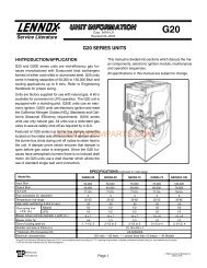
<strong>CB26</strong>UH AND CBX26UH PARTS ARRANGEMENT<br />
ELECTRIC HEAT SECTION<br />
(plate to be removed if installed)<br />
BLOWER COMPARTMENT<br />
CONTROL BOX<br />
COIL<br />
HORIZONTAL DRAIN PAN<br />
EXPANSION VALVE<br />
(R−22 or R−410A)<br />
UP−FLOW DRAIN PAN<br />
FIGURE 1<br />
Page 8
I−APPLICATION<br />
CAUTION<br />
Electrostatic discharge can affect electronic<br />
components. Take precautions during unit installation<br />
<strong>and</strong> service to protect the unit’s electronic<br />
controls. Precautions will help to avoid control<br />
exposure to electrostatic discharge by putting<br />
the unit, the control <strong>and</strong> the technician at the<br />
same electrostatic potential. Neutralize electrostatic<br />
charge by touching h<strong>and</strong> <strong>and</strong> all tools on an<br />
unpainted unit surface before performing any<br />
service procedure.<br />
All major blower coil components must be matched<br />
according to Lennox recommendations for the unit to be<br />
covered under warranty. Refer to the Engineering H<strong>and</strong>book<br />
for approved system matchups. A misapplied system will<br />
cause erratic operation <strong>and</strong> can result in early unit failure. The<br />
units come with factory installed check <strong>and</strong> expansion valve for<br />
all applications. The TXV valve has been installed internally for<br />
a cleaner installation <strong>and</strong> is accessible if required.<br />
II−UNIT COMPONENTS<br />
A−Control Box<br />
The <strong>CB26</strong>UH <strong>and</strong> CBX26UH control box is located above<br />
the blower section shown in figure 1. Line voltage <strong>and</strong><br />
electric heat connections are made in the control box.<br />
Optional electric heat fits through an opening located in the<br />
center of the control box. When electric heat is not used,<br />
cover plates cover the opening. The electric heat control<br />
arrangement is detailed in the electric heat section of this<br />
manual.<br />
1−Transformer<br />
All <strong>CB26</strong>UH <strong>and</strong> CBX26UH series units use a single line<br />
voltage to 24VAC transformer mounted in the control<br />
box. The transformer supplies power to the control<br />
circuits in the indoor <strong>and</strong> outdoor unit. Transformers are<br />
rated at 40VA. 208/240VAC single phase transformers use<br />
two primary voltage taps as shown in figure 2.<br />
208 / 240 VOLT TRANSFORMER<br />
240 VOLTS<br />
PRIMARY<br />
ORANGE<br />
RED<br />
208 VOLTS<br />
BLACK<br />
FIGURE 2<br />
BLUE<br />
YELLOW<br />
SECONDARY<br />
2−Blower Relay<br />
All <strong>CB26</strong>UH <strong>and</strong> CBX26UH units use a double−pole<br />
single−throw (DPST) switch relay to energize the blower<br />
motor. The relay coil is energized by blower dem<strong>and</strong><br />
from indoor thermostat. When the coil is energized, a set of<br />
normally open (N.O.) contacts closes to energize the blower<br />
motor on cooling speed. When de−energized, a set of normally<br />
closed (N.C.) contacts allows the electric heat relay to energize<br />
the blower on heating speed (refer to unit wiring diagram).<br />
3−Time Delay Relay<br />
The blower time delay is a 24 volt N.O. relay wired to the<br />
blower relay. See unit diagram. The delay is between 10<br />
<strong>and</strong> 60 seconds <strong>and</strong> delays the blower on <strong>and</strong> off time in the<br />
cooling cycle.<br />
BLOWER ASSEMBLY<br />
B−Blower Motor (B3)<br />
FIGURE 3<br />
<strong>CB26</strong>UH <strong>and</strong> CBX26UH units use single phase direct drive<br />
blower motors with a run capacitor. Figure 3 shows the<br />
parts arrangement. All motors have two speed taps.<br />
Typically, the high speed tap is energized during normal<br />
operation.<br />
All units are factory wired for the high blower speed for heat<br />
pump <strong>and</strong> cooling applications with or without electric heat. No<br />
field wiring is required. The wiring diagrams show factory set<br />
blower speeds.<br />
1−Blower Motor Capacitor<br />
All <strong>CB26</strong>UH <strong>and</strong> CBX26UH series units use single phase<br />
direct drive motors with a run capacitor. The run capacitor is<br />
mounted on the blower housing. See figure 3. Capacitor<br />
ratings are shown on side of capacitor <strong>and</strong> indoor blower motor<br />
nameplate.<br />
Page 9
C−Coil<br />
<strong>CB26</strong>UH <strong>and</strong> CBX26UH units have dual slab coils<br />
arranged in an A configuration. Each coil has two or three<br />
rows of copper tubes fitted with ripple−edged aluminum<br />
fins. An expansion valve, feeds multiple parallel circuits through<br />
the coils. The coil is designed to easily slide out of the unit<br />
cabinet.<br />
D−Plastic Drain Pans<br />
Drain pans are provided <strong>and</strong> installed on the <strong>CB26</strong>UH <strong>and</strong><br />
CBX26UH, The drain pans are made from fiberglass filled<br />
plastic.<br />
III−OPTIONAL E<strong>CB26</strong> ELECTRIC HEAT<br />
A−Matchups <strong>and</strong> Ratings<br />
Tables 2 through 5 show all approved <strong>CB26</strong>UH <strong>and</strong><br />
CBX26UH to E<strong>CB26</strong> matchups <strong>and</strong> electrical ratings.<br />
B−Electric Heat Components<br />
E<strong>CB26</strong> parts arrangement is shown in figure 4. All electric heat<br />
sections consist of components mounted to the electric heat<br />
vestibule panel <strong>and</strong> electric heating elements exposed directly<br />
to the airstream. 208/230V electric heat sections may be<br />
equipped with circuit breakers. The circuit breakers are<br />
designated by CB in the model number.<br />
1 − Electric Heat Sequencer Relays 1 <strong>and</strong> 2<br />
Relays are N.O. sequencer relays with a resistive<br />
element for a coil <strong>and</strong> a bi-metal disk which actuates<br />
the contacts. The relays are located on the electric heat<br />
vestibule panel <strong>and</strong> are energized by a 24V heating<br />
dem<strong>and</strong> (W1 <strong>and</strong> W2) via jack/plug 2. When energized,<br />
the internal resistance heats the bi-metal disk causing the<br />
contacts to close. When the relay is de-energized, the<br />
disk cools <strong>and</strong> the contacts open. The relays<br />
energize different stages of heat, as well as the<br />
blower. The blower is always first on <strong>and</strong> last off.<br />
2 − Primary Limits 1, 2, 3 & 4<br />
The primary limits are located on the electric heat vestibule<br />
panel <strong>and</strong> exposed directly to the airstream through an<br />
opening in the panel. They are SPST N.C. auto −reset<br />
limits. The limits are factory set <strong>and</strong> not adjustable.<br />
208/230 Volt Electric Heat Sections<br />
Each stage of the 208/230 electric heat is protected<br />
by a primary high temperature limit. Each stage uses the<br />
same style of limit. The primary limit is wired in series with<br />
a heat element. When either limit opens, the<br />
corresponding heat element is de-energized. All<br />
other heating elements remain energized. The primary<br />
high temperature limit opens at 150F + 5F (65.5C +<br />
2.8C) on a temperature rise <strong>and</strong> automatically resets<br />
at 110F + 9F (43.3C + 5.0C) on a temperature<br />
fall.<br />
3 − Circuit Breaker<br />
Line voltage connections are made to circuit breakers in<br />
the electric heat sections with circuit breakers (designated<br />
by CB in the model numbers). Table 1 shows the amp<br />
rating for each circuit breaker used. Single phase electric<br />
heat uses two pole circuit breakers.<br />
TABLE 1<br />
ECB29 CIRCUIT BREAKERS<br />
UNIT CB1 AMPS CB2 AMPS CB3 AMPS<br />
E<strong>CB26</strong>-5CB-1 (P) 30 AMP −−− −−−<br />
E<strong>CB26</strong>-7CB-1 (P) 45 AMP −−− −−−<br />
E<strong>CB26</strong>10CB-1 (P) 60 AMP −−− −−−<br />
E<strong>CB26</strong>-15CB-1 (P) 60 AMP 30 AMP −−−<br />
E<strong>CB26</strong>-20CB-1 (P) 60 AMP 60 AMP −−−<br />
4 − <strong>Heating</strong> Elements<br />
<strong>Heating</strong> elements are composed of helix wound bare<br />
nichrome wire exposed directly to the airstream. The<br />
elements are supported by insulators mounted to the<br />
wire frame. For single phase applications, one<br />
element is used per stage. Each stage is energized<br />
independently by the corresponding relay located<br />
on the electric heat vestibule panel. Once<br />
energized, heat transfer is instantaneous. High<br />
temperature protection is provided by primary high<br />
temperature limits.<br />
E<strong>CB26</strong>−7, -7CB, -10, -10CB 208/230<br />
VESTIBULE PARTS ARRANGEMENT<br />
ELECTRIC HEAT<br />
SEQUENCER<br />
1 & 2<br />
CIRCUIT BREAKER<br />
FIGURE 4<br />
HEATING ELEMENTS<br />
PRIMARY LIMITS<br />
1, 2, 3 & 4<br />
Page 10
SINGLE PHASE<br />
2.5 kW E<strong>CB26</strong>−2.5 (19W05)<br />
Terminal Block<br />
5 kW E<strong>CB26</strong>−5 (99M64)<br />
Terminal Block<br />
E<strong>CB26</strong>−5CB (99M65)<br />
Circuit Breaker<br />
7.5 kW E<strong>CB26</strong>−7 (99M67)<br />
Terminal Block<br />
E<strong>CB26</strong>−7CB (99M66)<br />
Circuit Breaker<br />
10 kW E<strong>CB26</strong>−10 (99M68)<br />
Terminal Block<br />
E<strong>CB26</strong>−10CB (99M69)<br />
Circuit Breaker<br />
TABLE 2<br />
Description Input Blower<br />
Motor<br />
Full Load<br />
Amps<br />
CB(X)26UH−018 / CBX26UH−024<br />
2 Minimum<br />
Circuit<br />
Ampacity<br />
3 Maximum<br />
Overcurrent<br />
Protection<br />
Volt kW 1 Btuh Ckt 1 Ckt 2 Ckt 1 Ckt 2 2 Minimum<br />
Circuit<br />
Ampacity<br />
Single Point<br />
Power Source<br />
3 Maximum<br />
Overcurrent<br />
Protection<br />
208 1.9 6,400 1.5 13.3 − − − 15 − − − − − − − − −<br />
220 2.1 7,200 1.4 13.7 − − − 15 − − − − − − − − −<br />
230 2.3 7,800 1.4 14.3 − − − 15 − − − − − − − − −<br />
240 2.5 8,500 1.4 14.8 − − − 15 − − − − − − − − −<br />
208 3.8 12,800 1.5 24.7 − − − 4 25 − − − − − − − − −<br />
220 4.2 14,300 1.4 25.6 − − − 30 − − − − − − − − −<br />
230 4.6 15,700 1.4 26.8 − − − 30 − − − − − − − − −<br />
240 5.0 17,100 1.4 27.8 − − − 30 − − − − − − − − −<br />
208 5.6 19,200 1.5 35.5 − − − 4 40 − − − − − − − − −<br />
220 6.3 21,500 1.4 37.5 − − − 4 40 − − − − − − − − −<br />
230 6.9 23,500 1.4 39.3 − − − 4 40 − − − − − − − − −<br />
240 7.5 25,600 1.4 40.8 − − − 45 − − − − − − − − −<br />
208 7.5 25,600 1.5 46.9 − − − 4 50 − − − − − − − − −<br />
220 8.4 28,700 1.4 49.5 − − − 4 50 − − − − − − − − −<br />
230 9.2 31,400 1.4 51.8 − − − 60 − − − − − − − − −<br />
240 10.0 34,100 1.4 53.8 − − − 60 − − − − − − − − −<br />
NOTE − Circuit 1 Minimum Circuit Ampacity includes the Blower Motor Full Load Amps.<br />
1 Electric heater capacity only − does not include additional blower motor heat capacity.<br />
2 Refer to National or Canadian Electrical Code manual to determine wire, fuse <strong>and</strong> disconnect size requirements. Use wires suitable for at least 167F.<br />
3 HACR type breaker or fuse.<br />
4 Bold indicates that the circuit breaker on CB" circuit breaker models must be replaced with size shown.<br />
Page 11
SINGLE PHASE<br />
2.5 kW E<strong>CB26</strong>−2.5 (19W05)<br />
Terminal Block<br />
5 kW E<strong>CB26</strong>−5 (99M64)<br />
Terminal Block<br />
E<strong>CB26</strong>−5CB (99M65)<br />
Circuit Breaker<br />
7.5 kW E<strong>CB26</strong>−7 (99M67)<br />
Terminal Block<br />
E<strong>CB26</strong>−7CB (99M66)<br />
Circuit Breaker<br />
10 kW E<strong>CB26</strong>−10 (99M68)<br />
Terminal Block<br />
E<strong>CB26</strong>−10CB (99M69)<br />
Circuit Breaker<br />
12.5 kW E<strong>CB26</strong>−12.5CB (19W00)<br />
Circuit Breaker<br />
15 kW E<strong>CB26</strong>−15CB (99M70)<br />
Circuit Breaker<br />
TABLE 3<br />
Description Input Blower<br />
Motor<br />
Full Load<br />
Amps<br />
CB(X)26UH−030<br />
2 Minimum<br />
Circuit<br />
Ampacity<br />
3 Maximum<br />
Overcurrent<br />
Protection<br />
Volt kW 1 Btuh Ckt 1 Ckt 2 Ckt 1 Ckt 2 2 Minimum<br />
Circuit<br />
Ampacity<br />
Single Point<br />
Power Source<br />
3 Maximum<br />
Overcurrent<br />
Protection<br />
208 1.9 6,400 1.6 13.4 − − − 15 − − − − − − − − −<br />
220 2.1 7,200 1.5 13.8 − − − 15 − − − − − − − − −<br />
230 2.3 7,800 1.5 14.4 − − − 15 − − − − − − − − −<br />
240 2.5 8,500 1.5 14.9 − − − 15 − − − − − − − − −<br />
208 3.8 12,800 1.6 24.8 − − − 4 25 − − − − − − − − −<br />
220 4.2 14,300 1.5 25.7 − − − 30 − − − − − − − − −<br />
230 4.6 15,700 1.5 26.9 − − − 30 − − − − − − − − −<br />
240 5.0 17,100 1.5 27.9 − − − 30 − − − − − − − − −<br />
208 5.6 19,200 1.6 35.7 − − − 4 40 − − − − − − − − −<br />
220 6.3 21,500 1.5 37.7 − − − 4 40 − − − − − − − − −<br />
230 6.9 23,500 1.5 39.4 − − − 4 40 − − − − − − − − −<br />
240 7.5 25,600 1.5 40.9 − − − 45 − − − − − − − − −<br />
208 7.5 25,600 1.6 47.1 − − − 4 50 − − − − − − − − −<br />
220 8.4 28,700 1.5 49.6 − − − 4 50 − − − − − − − − −<br />
230 9.2 31,400 1.5 51.9 − − − 60 − − − − − − − − −<br />
240 10.0 34,100 1.5 54.0 − − − 60 − − − − − − − − −<br />
208 9.4 32,000 1.6 35.8 22.6 4 40 4 25 59 60<br />
220 10.5 35,800 1.5 37.7 23.9 4 40 4 25 62 70<br />
230 11.5 39,200 1.5 39.3 24.9 4 40 4 25 65 70<br />
240 12.5 42,600 1.5 40.9 26.0 45 30 67 70<br />
208 11.3 38,400 1.6 47.1 22.6 4 50 4 25 70 70<br />
220 12.6 43,000 1.5 49.8 23.9 4 50 4 25 74 80<br />
230 13.5 47,000 1.5 51.8 24.9 60 4 25 77 80<br />
240 15.0 51,200 1.5 54.0 26.0 60 30 80 80<br />
NOTE − Circuit 1 Minimum Circuit Ampacity includes the Blower Motor Full Load Amps.<br />
1 Electric heater capacity only − does not include additional blower motor heat capacity.<br />
2 Refer to National or Canadian Electrical Code manual to determine wire, fuse <strong>and</strong> disconnect size requirements. Use wires suitable for at least 167F.<br />
3 HACR type breaker or fuse.<br />
4 Bold indicates that the circuit breaker on CB" circuit breaker models must be replaced with size shown.<br />
Page 12
SINGLE PHASE<br />
2.5 kW E<strong>CB26</strong>−2.5 (19W05)<br />
Terminal Block<br />
5 kW E<strong>CB26</strong>−5 (99M64)<br />
Terminal Block<br />
E<strong>CB26</strong>−5CB (99M65)<br />
Circuit Breaker<br />
7.5 kW E<strong>CB26</strong>−7 (99M67)<br />
Terminal Block<br />
E<strong>CB26</strong>−7CB (99M66)<br />
Circuit Breaker<br />
10 kW E<strong>CB26</strong>−10 (99M68)<br />
Terminal Block<br />
E<strong>CB26</strong>−10CB (99M69)<br />
Circuit Breaker<br />
12.5 kW E<strong>CB26</strong>−12.5CB (19W00)<br />
Circuit Breaker<br />
15 kW E<strong>CB26</strong>−15CB (99M70)<br />
Circuit Breaker<br />
TABLE 4<br />
Description Input Blower<br />
Motor<br />
Full Load<br />
Amps<br />
CB(X)26UH−036 / CBX26UH−037<br />
2 Minimum<br />
Circuit<br />
Ampacity<br />
3 Maximum<br />
Overcurrent<br />
Protection<br />
Volt kW 1 Btuh Ckt 1 Ckt 2 Ckt 1 Ckt 2 2 Minimum<br />
Circuit<br />
Ampacity<br />
Single Point<br />
Power Source<br />
3 Maximum<br />
Overcurrent<br />
Protection<br />
208 1.9 6,400 2.1 14.0 − − − 15 − − − − − − − − −<br />
220 2.1 7,200 2.0 14.4 − − − 15 − − − − − − − − −<br />
230 2.3 7,800 2.0 15.0 − − − 15 − − − − − − − − −<br />
240 2.5 8,500 2.0 15.5 − − − 20 − − − − − − − − −<br />
208 3.8 12,800 2.1 25.5 − − − 30 − − − − − − − − −<br />
220 4.2 14,300 2.0 26.4 − − − 30 − − − − − − − − −<br />
230 4.6 15,700 2.0 27.5 − − − 30 − − − − − − − − −<br />
240 5.0 17,100 2.0 28.5 − − − 30 − − − − − − − − −<br />
208 5.6 19,200 2.1 36.3 − − − 4 40 − − − − − − − − −<br />
220 6.3 21,500 2.0 38.3 − − − 4 40 − − − − − − − − −<br />
230 6.9 23,500 2.0 40.0 − − − 4 40 − − − − − − − − −<br />
240 7.5 25,600 2.0 41.6 − − − 45 − − − − − − − − −<br />
208 7.5 25,600 2.1 47.7 − − − 4 50 − − − − − − − − −<br />
220 8.4 28,700 2.0 50.2 − − − 60 − − − − − − − − −<br />
230 9.2 31,400 2.0 52.5 − − − 60 − − − − − − − − −<br />
240 10.0 34,100 2.0 54.6 − − − 60 − − − − − − − − −<br />
208 9.4 32,000 2.1 36.4 22.6 4 40 30 59 60<br />
220 10.5 35,800 2.0 38.3 23.9 4 40 30 63 70<br />
230 11.5 39,200 2.0 39.9 24.9 4 40 30 65 70<br />
240 12.5 42,600 2.0 41.6 26.0 45 30 68 70<br />
208 11.3 38,400 2.1 47.8 22.6 4 50 30 71 80<br />
220 12.6 43,000 2.0 50.5 23.9 60 30 75 80<br />
230 13.5 47,000 2.0 52.4 24.9 60 30 78 80<br />
240 15.0 51,200 2.0 54.6 26.0 60 30 81 90<br />
NOTE − Circuit 1 Minimum Circuit Ampacity includes the Blower Motor Full Load Amps.<br />
1 Electric heater capacity only − does not include additional blower motor heat capacity.<br />
2 Refer to National or Canadian Electrical Code manual to determine wire, fuse <strong>and</strong> disconnect size requirements. Use wires suitable for at least 167F.<br />
3 HACR type breaker or fuse.<br />
4 Bold indicates that the circuit breaker on CB" circuit breaker models must be replaced with size shown.<br />
Page 13
SINGLE PHASE<br />
2.5 kW E<strong>CB26</strong>−2.5 (19W05)<br />
Terminal Block<br />
5 kW E<strong>CB26</strong>−5 (99M64)<br />
Terminal Block<br />
E<strong>CB26</strong>−5CB (99M65)<br />
Circuit Breaker<br />
7.5 kW E<strong>CB26</strong>−7 (99M67)<br />
Terminal Block<br />
E<strong>CB26</strong>−7CB (99M66)<br />
Circuit Breaker<br />
10 kW E<strong>CB26</strong>−10 (99M68)<br />
Terminal Block<br />
E<strong>CB26</strong>−10CB (99M69)<br />
Circuit Breaker<br />
12.5 kW E<strong>CB26</strong>−12.5CB (19W00)<br />
Circuit Breaker<br />
15 kW E<strong>CB26</strong>−15CB (99M70)<br />
Circuit Breaker<br />
TABLE 5<br />
Description Input Blower<br />
Motor<br />
Full Load<br />
Amps<br />
CB(X)26UH−042<br />
2 Minimum<br />
Circuit<br />
Ampacity<br />
3 Maximum<br />
Overcurrent<br />
Protection<br />
Volt kW 1 Btuh Ckt 1 Ckt 2 Ckt 1 Ckt 2 2 Minimum<br />
Circuit<br />
Ampacity<br />
Single Point<br />
Power Source<br />
3 Maximum<br />
Overcurrent<br />
Protection<br />
208 1.9 6,400 2.6 14.7 − − − 15 − − − − − − − − −<br />
220 2.1 7,200 2.5 15.1 − − − 20 − − − − − − − − −<br />
230 2.3 7,800 2.5 15.6 − − − 20 − − − − − − − − −<br />
240 2.5 8,500 2.5 16.1 − − − 20 − − − − − − − − −<br />
208 3.8 12,800 2.6 26.1 − − − 30 − − − − − − − − −<br />
220 4.2 14,300 2.5 27.0 − − − 30 − − − − − − − − −<br />
230 4.6 15,700 2.5 28.1 − − − 30 − − − − − − − − −<br />
240 5.0 17,100 2.5 29.2 − − − 30 − − − − − − − − −<br />
208 5.6 19,200 2.6 36.9 − − − 4 40 − − − − − − − − −<br />
220 6.3 21,500 2.5 38.9 − − − 4 40 − − − − − − − − −<br />
230 6.9 23,500 2.5 40.6 − − − 45 − − − − − − − − −<br />
240 7.5 25,600 2.5 42.2 − − − 45 − − − − − − − − −<br />
208 7.5 25,600 2.6 48.3 − − − 4 50 − − − − − − − − −<br />
220 8.4 28,700 2.5 50.9 − − − 60 − − − − − − − − −<br />
230 9.2 31,400 2.5 53.1 − − − 60 − − − − − − − − −<br />
240 10.0 34,100 2.5 55.2 − − − 60 − − − − − − − − −<br />
208 9.4 32,000 2.6 37.1 22.6 4 40 4 25 60 60<br />
220 10.5 35,800 2.5 38.9 23.9 4 40 4 25 63 70<br />
230 11.5 39,200 2.5 40.5 24.9 45 4 25 66 70<br />
240 12.5 42,600 2.5 42.2 26.0 45 30 69 70<br />
208 11.3 38,400 2.6 48.4 22.6 4 50 25 71 80<br />
220 12.6 43,000 2.5 51.1 23.9 60 4 25 75 80<br />
230 13.5 47,000 2.5 53.0 24.9 60 4 25 78 80<br />
240 15.0 51,200 2.5 55.2 26.0 60 30 82 90<br />
NOTE − Circuit 1 Minimum Circuit Ampacity includes the Blower Motor Full Load Amps.<br />
1 Electric heater capacity only − does not include additional blower motor heat capacity.<br />
2 Refer to National or Canadian Electrical Code manual to determine wire, fuse <strong>and</strong> disconnect size requirements. Use wires suitable for at least 167F.<br />
3 HACR type breaker or fuse.<br />
4 Bold indicates that the circuit breaker on CB" circuit breaker models must be replaced with size shown.<br />
Page 14
SINGLE PHASE<br />
2.5 kW E<strong>CB26</strong>−2.5 (19W05)<br />
Terminal Block<br />
5 kW E<strong>CB26</strong>−5 (99M64)<br />
Terminal Block<br />
E<strong>CB26</strong>−5CB (99M65)<br />
Circuit Breaker<br />
7.5 kW E<strong>CB26</strong>−7 (99M67)<br />
Terminal Block<br />
E<strong>CB26</strong>−7CB (99M66)<br />
Circuit Breaker<br />
10 kW E<strong>CB26</strong>−10 (99M68)<br />
Terminal Block<br />
E<strong>CB26</strong>−10CB (99M69)<br />
Circuit Breaker<br />
12.5 kW E<strong>CB26</strong>−12.5CB (19W00)<br />
Circuit Breaker<br />
15 kW E<strong>CB26</strong>−15CB (99M70)<br />
Circuit Breaker<br />
20 kW E<strong>CB26</strong>−20CB (99M71)<br />
Circuit Breaker<br />
TABLE 6<br />
Description Input Blower<br />
Motor<br />
Full Load<br />
Amps<br />
(240V)<br />
CB(X)26UH−048−060<br />
2 Minimum<br />
Circuit<br />
Ampacity<br />
3 Maximum<br />
Overcurrent<br />
Protection<br />
Volt kW 1 Btuh Ckt 1 Ckt 2 Ckt 1 Ckt 2 2 Minimum<br />
Circuit<br />
Ampacity<br />
Single Point<br />
Power Source<br />
3 Maximum<br />
Overcurrent<br />
Protection<br />
208 1.9 6,400 4.1 16.5 − − − 20 − − − − − − − − −<br />
220 2.1 7,200 3.9 16.8 − − − 20 − − − − − − − − −<br />
230 2.3 7,800 3.9 17.4 − − − 20 − − − − − − − − −<br />
240 2.5 8,500 3.9 17.9 − − − 20 − − − − − − − − −<br />
208 3.8 12,800 4.1 28.0 − − − 30 − − − − − − − − −<br />
220 4.2 14,300 3.9 28.7 − − − 30 − − − − − − − − −<br />
230 4.6 15,700 3.9 29.9 − − − 30 − − − − − − − − −<br />
240 5.0 17,100 3.9 30.9 − − − 4 35 − − − − − − − − −<br />
208 5.6 19,200 4.1 38.8 − − − 4 40 − − − − − − − − −<br />
220 6.3 21,500 3.9 40.7 − − − 45 − − − − − − − − −<br />
230 6.9 23,500 3.9 42.4 − − − 45 − − − − − − − − −<br />
240 7.5 25,600 3.9 43.9 − − − 45 − − − − − − − − −<br />
208 7.5 25,600 4.1 50.2 − − − 60 − − − − − − − − −<br />
220 8.4 28,700 3.9 52.6 − − − 60 − − − − − − − − −<br />
230 9.2 31,400 3.9 54.9 − − − 60 − − − − − − − − −<br />
240 10.0 34,100 3.9 57.0 − − − 60 − − − − − − − − −<br />
208 9.4 32,000 4.1 38.9 22.6 4 40 25 62 70<br />
220 10.5 35,800 3.9 40.7 23.9 45 25 65 70<br />
230 11.5 39,200 3.9 42.3 24.9 45 25 68 70<br />
240 12.5 42,600 3.9 43.9 26.0 45 30 70 70<br />
208 11.3 38,400 4.1 50.3 22.6 60 25 73 80<br />
220 12.6 43,000 3.9 52.8 23.9 60 25 77 80<br />
230 13.5 47,000 3.9 54.8 24.9 60 25 80 80<br />
240 15.0 51,200 3.9 57.0 26.0 60 30 83 90<br />
208 15.0 51,200 4.1 50.3 45.1 60 4 50 96 100<br />
220 16.8 57,300 3.9 52.8 48.0 60 4 50 101 110<br />
230 18.4 62,700 3.9 54.8 49.9 60 4 50 105 110<br />
240 20.0 68,200 3.9 57.0 52.1 60 60 110 110<br />
NOTE − Circuit 1 Minimum Circuit Ampacity includes the Blower Motor Full Load Amps.<br />
1 Electric heater capacity only − does not include additional blower motor heat capacity.<br />
2 Refer to National or Canadian Electrical Code manual to determine wire, fuse <strong>and</strong> disconnect size requirements. Use wires suitable for at least 167F.<br />
3 HACR type breaker or fuse.<br />
4 Bold indicates that the circuit breaker on CB" circuit breaker models must be replaced with size shown.<br />
Page 15
IV−CONFIGURATION MODIFICATIONS<br />
<strong>CB26</strong>UH <strong>and</strong> CBX26UHunits are factory−assembled <strong>and</strong><br />
configured for installation in upflow or horizontal left−h<strong>and</strong><br />
air discharge applications. A kit is available to convert units<br />
for downflow applications. See OPTIONAL<br />
ACCESSORIES at the front of this manual.<br />
If the unit needs to be modified from its original<br />
configuration, use the following procedures. All procedures<br />
assume the unit has not been modified from the factory.<br />
General Information<br />
WARNING<br />
Improper installation, adjustment, alteration, service<br />
or maintenance can cause property damage, personal<br />
injury or loss of life. Installation <strong>and</strong> service must<br />
be performed by a qualified installer or service<br />
agency.<br />
Each unit consists of a blower assembly, refrigerant coil,<br />
<strong>and</strong> controls, in an insulated galvanized steel factory<br />
finished enclosure. Knockouts are provided for electrical<br />
wiring entrance.<br />
For ease in installation, it is best to make any necessary coil<br />
configuration changes before setting air h<strong>and</strong>ler in place.<br />
If a filter is to be installed at the air h<strong>and</strong>ler, a filter rack must<br />
be formed using factory−supplied flanges. Lay the unit on its<br />
back <strong>and</strong> pry out the filter rack tabs as shown in figure 5.<br />
Filter Rack Tabs<br />
4. Install units that have no return air plenum on a st<strong>and</strong><br />
that is at least 14" from the floor. This will allow proper<br />
air return.<br />
HORIZONTAL<br />
DRAIN PAN<br />
(Remove for best<br />
upflow performance)<br />
Upflow Configuration<br />
UPFLOW<br />
DRAIN PAN<br />
UPFLOW DRAIN<br />
CONNECTIONS<br />
(Both sides; use<br />
on side or other)<br />
FIGURE 6<br />
HORIZONTAL<br />
DRAIN<br />
CONNECTIONS<br />
(Both sides; Not<br />
used)<br />
Horizontal Applications<br />
NOTE − When the unit is installed in horizontal applications,<br />
a secondary drain pan is recommended. Refer to local<br />
codes.<br />
This unit may be installed in left−h<strong>and</strong> or right−h<strong>and</strong> air<br />
discharge horizontal applications. Adequate support must<br />
be provided to ensure cabinet integrity. Ensure that there is<br />
adequate room to remove service <strong>and</strong> access panels if<br />
installing in the horizontal position.<br />
1. Determine whether left-h<strong>and</strong> or right-h<strong>and</strong> air<br />
discharge is required. If right-h<strong>and</strong> is required, perform<br />
Right−H<strong>and</strong> Discharge Modification. See next page.<br />
2. Determine knockouts required for drain line<br />
connections.<br />
3. With access door removed, knock out drain line<br />
opening for installing drain lines.<br />
4. Set unit so that it is sloped (up to 1/4 inch) toward the<br />
drain pan end of the unit.<br />
5. The horizontal configuration is shown in figure 7.<br />
Left−H<strong>and</strong> <strong>Air</strong> Discharge Configuration<br />
FIGURE 5<br />
AIR<br />
FLOW<br />
Drains<br />
Upflow Application<br />
1. The air h<strong>and</strong>ler must be supported on the bottom only<br />
<strong>and</strong> set on solid floor or field-supplied support frame.<br />
Securely attach the air h<strong>and</strong>ler to the floor or support<br />
frame.<br />
2. If installing a unit in an upflow application, remove the<br />
horizontal drain pan; it is not required in upflow air<br />
discharge installations.<br />
3. Place the unit in desired location. Set unit so that it is<br />
level. Connect return <strong>and</strong> supply air plenums as<br />
required using sheet metal screws.<br />
KNOCKOUT<br />
FIGURE 7<br />
LEFT-HAND DRAINS<br />
6. If the unit is suspended, the entire length of the cabinet<br />
must be supported. If you use a chain or strap, use a<br />
piece of angle iron or sheet metal attached to the unit<br />
(either above or below) to support the length of the<br />
cabinet. Use securing screws no longer than 1/2 inch<br />
to avoid damaging the coil or filter. See figure 8. Use<br />
sheet metal screws to connect the return <strong>and</strong> supply air<br />
plenums as required.<br />
Page 16
Suspending Horizontal Unit<br />
ANGLE IRON OR<br />
SHEET METAL<br />
1/2 in. Screws max.<br />
AIR<br />
FLOW<br />
FRONT VIEW<br />
FIGURE 8<br />
IMPORTANT<br />
Electrical Inlet Clearance<br />
4 in. (102 mm)<br />
END VIEW<br />
When removing the coil, there is possible danger of<br />
equipment damage <strong>and</strong> personal injury. Be careful<br />
when removing the coil assembly from a unit<br />
installed in right− or left−h<strong>and</strong> applications. The coil<br />
may tip into the drain pan once it is clear of the cabinet.<br />
Support the coil when removing it.<br />
Right−H<strong>and</strong> <strong>Air</strong> Discharge Modification<br />
Right−H<strong>and</strong> <strong>Air</strong> Discharge Configuration<br />
Drains<br />
AIR<br />
FLOW<br />
Field Modification for Right−H<strong>and</strong> Discharge<br />
REMOVE<br />
DRAIN PAN<br />
FROM HERE<br />
THEN...<br />
DETAIL A<br />
REINSTALL<br />
PAN HERE<br />
REMOVE 2<br />
SCREWS AND<br />
BP BRACKET<br />
FROM HERE<br />
THEN...<br />
ROTATE BP<br />
BRACKET AND<br />
REINSTALL<br />
REMOVE<br />
COIL SUPPORT<br />
BRACKET<br />
FROM HERE<br />
THEN...<br />
REINSTALL<br />
BRACKET<br />
HERE<br />
BRACKET<br />
SHOWN AS<br />
SHIPPED<br />
BRACKET<br />
SHOWN FOR<br />
RIGHT HAND<br />
DISCHARGE<br />
DETAIL B<br />
FIGURE 10<br />
Right-H<strong>and</strong> Discharge Drain Plug Location<br />
KNOCKOUT<br />
RIGHT-HAND DRAINS<br />
FIGURE 9<br />
For horizontal right−h<strong>and</strong> air discharge, the following field<br />
modifications are required.<br />
1. Remove <strong>and</strong> set aside blower <strong>and</strong> coil access covers.<br />
2. Remove the coil support bracket (see detail A, figure<br />
10).<br />
3. Remove coil assembly, bottom drain pan <strong>and</strong><br />
horizontal drain pan as one assembly from the air<br />
h<strong>and</strong>ler.<br />
4. Remove the drain plugs from back of horizontal drain<br />
pan <strong>and</strong> reinstall in the front holes.<br />
5. Remove two screws <strong>and</strong> blowoff prevention bracket<br />
(BP BRACKET in figure 10). Rotate the bracket 180º<br />
<strong>and</strong> reinstall using the same screws.<br />
6. Move horizontal drain pan to the opposite side of the<br />
coil. Plugged drain holes will now be toward the back<br />
of the unit (see figure 11).<br />
7. Re−install modified coil/drain pan assembly in air<br />
h<strong>and</strong>ler in the same orientation as before.<br />
8. Install the coil support bracket on the opposite side of<br />
the air h<strong>and</strong>ler (detail B, figure 10)..<br />
ORIGINAL<br />
PLUG<br />
LOCATION<br />
NEW PLUG<br />
LOCATION<br />
COIL<br />
ASSEMBLY<br />
FIGURE 11<br />
PLUGGED<br />
END<br />
OPEN END FOR<br />
CONDENSATION<br />
DRAIN<br />
Install Condensate Drain<br />
The air h<strong>and</strong>ler is provided with ¾" NPT condensate drain<br />
connections.<br />
IMPORTANT<br />
A field−fabricated secondary drain pan, with a drain<br />
pipe to the outside of the building, is required in all<br />
installations over a finished living space or in any<br />
area that may be damaged by overflow from the main<br />
drain pan. In some localities, local codes may require<br />
an secondary drain pan for any horizontal installation.<br />
Page 17
Make sure the unit is sloped (up to 1/4 inch) so that the drain<br />
pan will empty completely without water st<strong>and</strong>ing in the<br />
pan. See figure 12.<br />
THIS CORNER<br />
SHOULD BE<br />
5/8 (+/− 1/8)<br />
HIGHER THAN<br />
DRAIN CORNER<br />
DRAIN CORNER<br />
FIGURE 12<br />
THIS CORNER<br />
SHOULD BE<br />
5/8 (+/− 1/8)<br />
HIGHER THAN<br />
DRAIN CORNER<br />
1. Remove the appropriate drain knockouts. If necessary,<br />
remove the indoor coil assembly from the cabinet.<br />
2. Connect primary drain line connection to the primary<br />
drain pan connection. The primary drain connection is<br />
flush with the bottom of the inside of the pan.<br />
Secondary connection is raised above the bottom of<br />
the inside of the pan.<br />
NOTE − When making drain fitting connections to the drain<br />
pan, h<strong>and</strong> tighten the fitting <strong>and</strong> use a sealant.<br />
Overtightening the fittings can split connections on the<br />
drain pan.<br />
3. Secondary drain connections, if used, should be<br />
connected to a separate drainage system. Run the<br />
secondary drain line to a place where the occupant<br />
would be sure to notice any drainage from the drain.<br />
4. Install a 3" trap in both the primary <strong>and</strong> secondary drain<br />
lines as close to the unit as practical (see figure 13).<br />
Make sure the top of the trap is below the connection<br />
to the drain pan to allow complete drainage of the pan.<br />
Typical Condensate Drain Connection<br />
(Secondary Drain Not Shown)<br />
AIR<br />
HANDLER<br />
DRAIN PAN<br />
DRAIN CONNECTION<br />
ANTI−SIPHON<br />
DRAIN LINE AIR VENT<br />
12" Max.<br />
DRAIN TRAP<br />
FIGURE 13<br />
1" Min.<br />
3" Min.<br />
NOTE − Horizontal runs over 15 ft. long must also have an<br />
antisiphon air vent (st<strong>and</strong>pipe) installed ahead of the<br />
horizontal run (See figure 13). An extremely long horizontal<br />
run may require an oversized drain line to eliminate air<br />
trapping.<br />
NOTE − Do not operate air h<strong>and</strong>ler without a drain trap. The<br />
condensate drain is on the negative pressure side of the<br />
blower; therefore, air being pulled through the condensate<br />
line will prevent positive drainage without a proper trap.<br />
5. Route the drain line to the outside or to an appropriate<br />
drain. Drain lines must be installed so they do not block<br />
service access to the front of the air h<strong>and</strong>ler. A 24"<br />
clearance is required for filter, coil, or blower removal<br />
<strong>and</strong> service access.<br />
NOTE − Check local codes before connecting the drain line<br />
to an existing drainage system.<br />
6. Insulate the drain lines where sweating could cause<br />
water damage.<br />
Test Condensate Drain<br />
Test the drain pan <strong>and</strong> drain line after installation:<br />
1. Pour several quarts of water into drain pan, enough to<br />
fill drain trap <strong>and</strong> line.<br />
2. Check to make sure the drain pan is draining<br />
completely, no leaks are found in drain line fittings, <strong>and</strong><br />
water is draining from the end of the primary drain line.<br />
3. Correct any leaks found.<br />
V−START-UP − OPERATION<br />
A−Preliminary <strong>and</strong> Seasonal Checks<br />
1− Make sure the unit is installed in accordance with the<br />
installation instructions.<br />
2− Inspect electrical wiring, both field <strong>and</strong> factory installed for<br />
loose connections. Tighten as required.<br />
3− Check voltage at disconnect switch. Voltage must be<br />
within range listed on the nameplate. If not, consult the<br />
power company <strong>and</strong> have voltage condition<br />
corrected before starting unit.<br />
4− Check to ensure that refrigerant lines are in good<br />
condition <strong>and</strong> pipe insulation is intact.<br />
5− Inspect condition of condensate drain pan <strong>and</strong> piping<br />
assembly. Disassemble <strong>and</strong> clean seasonally.<br />
B−Cooling Start-Up<br />
NOTE−The following is a generalized procedure <strong>and</strong><br />
does not apply to all thermostat control systems. Electronic<br />
thermostat control systems may operate differently.<br />
1− Set fan switch to AUTO or ON <strong>and</strong> move the system<br />
selection switch to COOL. Adjust the thermostat to a<br />
setting far enough below room temperature to bring on<br />
the compressor. Compressor will start <strong>and</strong> cycle on<br />
dem<strong>and</strong> from the thermostat. After a 30 second time<br />
delay (approximate) the indoor blower will energize.<br />
2− The refrigerant circuit is charged with HCFC−22 or<br />
HFC−410A refrigerant. See condensing unit rating<br />
plate for correct charge amount.<br />
3− Refer to the correct condensing unit service manual for<br />
more information.<br />
C−<strong>Heating</strong> Start-Up<br />
1− Set the fan switch to AUTO or ON <strong>and</strong> move the<br />
system selection switch to HEAT. Adjust the<br />
thermostat setting above room temperature.<br />
2− The indoor blower <strong>and</strong> the electric heat will stage on based<br />
on sequencer timing.<br />
D−Safety or Emergency Shutdown<br />
Turn off unit power at circuit breaker.<br />
E−Extended Period Shutdown<br />
Turn off thermostat or set to UNOCCUPIED mode. Turn off<br />
power to unit. All access panels <strong>and</strong> covers must be in place<br />
Page 18
<strong>and</strong> secured. The condensate assembly should be clean<br />
<strong>and</strong> dry for extended period shutdown.<br />
VI−TYPICAL OPERATING CHARACTERISTICS<br />
A−Blower Operation <strong>and</strong> Adjustment<br />
NOTE− The following is a generalized procedure <strong>and</strong><br />
does not apply to all thermostat controls.<br />
1− Blower operation is dependent on thermostat<br />
control system.<br />
2− Generally, blower operation is set at thermostat<br />
subbase fan switch. With fan switch in ON position,<br />
blower operates continuously. With fan switch in AUTO<br />
position, blower cycles with dem<strong>and</strong>.<br />
3− In all cases, blower <strong>and</strong> entire unit will be off when the<br />
system switch is in OFF position.<br />
B−External Static Pressure<br />
1− Measure tap locations as shown in figure 14.<br />
SUPPLY<br />
STATIC PRESSURE TEST<br />
MANOMETER<br />
FIGURE 14<br />
RETURN<br />
UNIT SHOWN IN<br />
HORIZONTAL DISCHARGE LEFT POSITION<br />
2− Punch a 1/4" (6mm) diameter hole in supply <strong>and</strong> return<br />
air plenums. Insert manometer hose flush with inside<br />
edge of hole or insulation. Seal around the hose with<br />
permagum. Connect the zero end of the manometer to<br />
the discharge (supply) side of the system. On ducted<br />
systems, connect the other end of manometer to the<br />
return duct as above. For systems with non−ducted<br />
returns, leave the other end of the manometer open to<br />
the atmosphere.<br />
3− With only the blower motor running <strong>and</strong> the<br />
evaporator coil dry, observe the manometer<br />
reading. Adjust blower motor speed to deliver the air<br />
desired according to the job requirements.<br />
4− For best air performance external static pressure<br />
drop must not exceed 0.5" W.C. (1.2 kPa). Refer to<br />
blower data tables for cfm <strong>and</strong> external static.<br />
5− Seal around the hole when the check is complete.<br />
C−Blower Speed Taps<br />
Change Blower Speed<br />
WARNING<br />
Electric shock hazard! − Disconnect all<br />
power supplies before servicing.<br />
Replace all parts <strong>and</strong> panels before<br />
operating.<br />
Failure to do so can result in death or<br />
electrical shock.<br />
1. Disconnect all power supplies.<br />
2. Remove the air h<strong>and</strong>ler access panel.<br />
3. Locate pin number 2 on the blower relay. Two black<br />
wires are connected to this terminal pin. One connects<br />
to pin number 5 on the blower relay, one connects to an<br />
inline splice connecting to a red or blue wire.<br />
4. Remove the wire going to the 4−pin blower motor<br />
connector from the splice.<br />
5. Connect the blower lead [Red (LO), Black (HI)] onto the<br />
splice from the 4−pin blower motor connector.<br />
NOTE − Unused blower speed taps are factory−covered<br />
with plastic caps. Remove this cap from the desired blower<br />
speed tap <strong>and</strong> replace it over the factory−set blower tap.<br />
6. Replace all panels.<br />
7. Reconnect power.<br />
VII−MAINTENANCE<br />
WARNING<br />
Disconnect power before performing any<br />
maintenance.<br />
At the beginning of each heating/cooling season, the<br />
system should be checked as follows:<br />
A−Filters<br />
NOTE− Filter access panel must be in place during unit<br />
operation, or excessive warm air may enter the unit<br />
resulting in water blow−off problems.<br />
TABLE 7<br />
Unit <strong>Air</strong> Filter Size Chart<br />
Model<br />
Filter Size<br />
18 / 24 16" x 20"<br />
30 / 36 18" x 20"<br />
42 / 48 / 60 18" x 25"<br />
To remove filter, remove 1/4" head screws holding the<br />
filter panel in place. Slide filter out of the guides on either<br />
side of cabinet, insert new filter <strong>and</strong> replace panel.<br />
Filters should be inspected monthly <strong>and</strong> must be<br />
replaced when dirty to ensure proper blower coil<br />
operation. See table 7 for replacement filter sizes.<br />
B−Supply <strong>Air</strong> Blower<br />
1- Check <strong>and</strong> clean blower wheel.<br />
2- Motors are prelubricated for extended life; no further<br />
lubrication is required.<br />
C−Electrical<br />
1- Check all wiring for loose connections.<br />
2- Check circuit breaker located in unit control box.<br />
3- Check for correct voltage at unit (unit operating).<br />
4- Check amp-draw on blower motor.<br />
5- Check to see that heat (if applicable) is operating.<br />
Page 19
VIII−WIRING DIAGRAMS AND SEQUENCE OF OPERATIONS<br />
220<br />
208/240<br />
VOLTAGE<br />
BY<br />
OTHERS<br />
CIRCUIT BREAKER 2 (OPT)<br />
L1B<br />
L2B<br />
GND<br />
CIRCUIT BREAKER 1 (OPT)<br />
L1A<br />
L2A<br />
12 BK<br />
12 BK<br />
12 BK<br />
12 BK<br />
18 BU<br />
SEQUENCER 2<br />
5 4<br />
3 1<br />
12 Y<br />
12 Y<br />
SEQUENCER 1<br />
5 4<br />
3 1<br />
18 BK<br />
12 BK<br />
12 BK<br />
3<br />
6<br />
ELECTRIC HEAT − 2ND STAGE<br />
LIMIT SWITCH 3<br />
LIMIT SWITCH 4<br />
HE4<br />
7<br />
HE3<br />
ELECTRIC HEAT − 1ST STAGE<br />
LIMIT SWITCH 1<br />
12 BK<br />
4<br />
12 BK<br />
12 Y<br />
LIMIT SWITCH 2<br />
HE2<br />
HE1<br />
14 BK<br />
14 BK L1<br />
GND<br />
TO BLOWER<br />
GROUND LUG<br />
6−PIN<br />
1 2 3 4 PLUG 5 6<br />
1 2 3 4 5 6<br />
COM<br />
14 Y<br />
14 Y L2<br />
208V<br />
240V<br />
1<br />
TRANSFORMER<br />
24<br />
24V<br />
C<br />
14 G<br />
18 R<br />
18 BU<br />
14 R<br />
18 BU<br />
H<br />
12 Y<br />
H<br />
18 W<br />
8<br />
3<br />
18 BK<br />
6<br />
18 BK<br />
18 W<br />
18 BU<br />
18 G<br />
18 R<br />
POWER (FACTORY WIRED)<br />
POWER (FIELD WIRED)<br />
CONTROL (FACTORY WIRED)<br />
CONTROL (FIELD WIRED)<br />
CONTROL CIRCUIT WIRING TO BE 24 VOLT, N.E.C. CLASS 2<br />
W2<br />
W1<br />
C<br />
G<br />
R<br />
BK<br />
W<br />
BU<br />
G<br />
R<br />
TO THERMOSTAT<br />
2<br />
1 2 3<br />
4 5 6<br />
6−PIN<br />
PLUG<br />
HEATER ELEMENTS USED:<br />
5KW − HE1<br />
7.5 & 10KW − HE1 & HE2<br />
15KW − HE1, HE2, & HE3<br />
20KW − HE1, HE2, HE3, & HE4<br />
14 BK<br />
18 BU<br />
14 R<br />
3<br />
6<br />
18 BU<br />
18 G<br />
4<br />
BLOWER<br />
RELAY<br />
TIME DELAY<br />
H =10 TO 60 SECONDS TO HEAT UP<br />
C =10 TO 60 SECONDS TO COOL DOWN<br />
1<br />
5<br />
5<br />
2<br />
14 R (LO)<br />
9 14 BK (HI)<br />
14 Y (COM)<br />
4<br />
3<br />
2<br />
1<br />
BR/W<br />
R<br />
BLOWER<br />
BK MOTOR<br />
Y+ BR MOTOR<br />
CAPACITOR<br />
Figure 15. Wiring Diagram CB(X)26UH−0XX−(R)−230−01 <strong>and</strong> CB(X)26UH−0XX−(R)−230−02 Builds<br />
Page 20
WARNING<br />
USE COPPER<br />
CONDUCTORS<br />
ONLY<br />
Figure 16. Wiring Diagram Applicable to units with a three speed motor with date of manufacture date code of January<br />
2009 through January 2010:<br />
Page 21
A−E<strong>CB26</strong>UH & ECBX26UH − SEQUENCE OF OPERATION<br />
FIRST STAGE HEAT<br />
1− Line voltage is routed to transformer <strong>and</strong> blower<br />
relay.<br />
2− 24VAC is supplied to indoor thermostat <strong>and</strong> electric<br />
heat, if used.<br />
COOLING<br />
3− When there is a call for heat W1 of the thermostat<br />
energizes sequencer relay 1.<br />
8−<br />
4− Assuming limit switch 1 <strong>and</strong> 2 are closed, sequencer<br />
relay 1 energizes HE1 <strong>and</strong> HE2.<br />
9−<br />
5− Indoor blower is energized on heating speed, after<br />
sequencer timing is complete.<br />
SECOND STAGE HEAT<br />
6− W2 in the thermostat energizes sequencer relay 2.<br />
7− Assuming limit switch 3 <strong>and</strong> 4 are closed sequencer<br />
relay energizes HE3 <strong>and</strong> HE4.<br />
When there is a call for cooling, G of the thermostat<br />
energizes blower time delay relay.<br />
After a 30 second delay (approximate) blower relay<br />
energizes blower motor on cooling speed. Blower will also<br />
delay 30 seconds after cool dem<strong>and</strong> is satisfied.<br />
Page 22