g61 service manual - Heating and Air Parts
g61 service manual - Heating and Air Parts
g61 service manual - Heating and Air Parts

You also want an ePaper? Increase the reach of your titles
YUMPU automatically turns print PDFs into web optimized ePapers that Google loves.
Service LiteratureCorp. 0310−L7Revised 1−2009G61MPVG61MPV SERIES UNITSG61MPV series units are high−efficiency multi−position(upflow, downflow, horizontal right <strong>and</strong> left) gas furnacesmanufactured with Lennox Duralok Plus heat exchangersformed of an aluminized steel primary with a stainlesssteel secondary condensing coil. G61MPV units are availablein heating capacities of 44,000 to 132,000 Btuh(13.0.0 to 38.6 kW) <strong>and</strong> cooling applications from 2 to 5tons (7.0 kW to 17.5 kW). Refer to Engineering H<strong>and</strong>bookfor proper sizing.Units are factory equipped for use with natural gas. Kits areavailable for conversion to LPG operation. G61MPV modelunits are equipped with the two−stage variable speed integratedSureLight® control. All G61MPV units meet the CaliforniaNitrogen Oxides (NO x ) St<strong>and</strong>ards <strong>and</strong> California SeasonalEfficiency requirements. All units use a redundant gasvalve to assure safety shut−off as required by C.S.A.All specifications in this <strong>manual</strong> are subject to change. Proceduresoutlined in this <strong>manual</strong> are presented as a recommendationonly <strong>and</strong> do not supersede or replace local orstate codes. In the absence of local or state codes, theguidelines <strong>and</strong> procedures outlined in this <strong>manual</strong> (exceptwhere noted) are recommendations only <strong>and</strong> do not constitutecode.TABLE OF CONTENTSSpecifications . . . . . . . . . . . . . . . . . . . . . . . . . . . . . Page 2Blower Data . . . . . . . . . . . . . . . . . . . . . . . . . . . . . . Page 4<strong>Parts</strong> Identification . . . . . . . . . . . . . . . . . . . . . . . . Page 23I Unit Components . . . . . . . . . . . . . . . . . . . . . . . . Page 24II Installation . . . . . . . . . . . . . . . . . . . . . . . . . . . . Page 47III Start Up . . . . . . . . . . . . . . . . . . . . . . . . . . . . . . . Page 61IV <strong>Heating</strong> System Service Checks . . . . . . . . . Page 62V Typical Operating Characteristics . . . . . . . . . Page 67VI Maintenance . . . . . . . . . . . . . . . . . . . . . . . . . . Page 68VII Wiring <strong>and</strong> Sequence of Operation . . . . . . . Page 71VIII Field Wiring <strong>and</strong> Jumper Setting . . . . . . . . Page 86IX Control Board Troubleshooting . . . . . . . . . . . Page 91IMPORTANTImproper installation, adjustment, alteration, <strong>service</strong>or maintenance can cause property damage, personalinjury or loss of life. Installation <strong>and</strong> <strong>service</strong> mustbe performed by a qualified installer, <strong>service</strong> agencyor the gas supplier.WARNINGElectric shock hazard. Can cause injuryor death. Before attempting to performany <strong>service</strong> or maintenance, turn theelectrical power to unit OFF at disconnectswitch(es). Unit may have multiplepower supplies.WARNINGSharp edges.Be careful when servicing unit to avoid sharp edgeswhich may result in personal injury.Page 1© 2003 Lennox Industries Inc.
SPECIFICATIONSGas<strong>Heating</strong>PerformanceModelNo.G61MPV−36B−045G61MPV−36B−070G61MPV−36B−071G61MPV−36C−090High Fire Input− Btuh 44,000 66,000 66,000 88,000Output− Btuh 39,000 61,000 62,000 79,000Temperature rise range − F 20 − 50 45 − 75 45 − 75 70 − 100Gas Manifold Pressure (in. w.g.)Natural Gas / LPG/Propane3.5 / 10.0 3.5 / 10.0 3.5 / 10.0 3.5 / 10.0Low Fire Input − Btuh 30,000 45,000 45,000 60,000Output − Btuh 29,000 43,000 43,000 56,000Temperature rise range − F 10 − 40 25 − 55 20 − 50 35 − 65Gas Manifold Pressure (in. w.g.)Natural Gas / LPG/Propane1.7 / 4.9 1.7 / 4.9 1.7 / 4.9 1.7 / 4.91 AFUE 94.1% 94.1% 95.0% 94.3%Highstatic(CSA)− in.w.g. .80 .80 .80 .80ConnectionsIntake / Exhaust Pipe (PVC) 2 / 2 2 / 2 2 / 2 2 / 2in.Condensate Drain Trap (PVC pipe) − i.d. 1/2 1/2 1/2 1/2with field supplied (PVC coupling) − o.d. 3/4 3/4 3/4 3/4hose with hose clamp − i.d. x o.d. 1−1/4 x 1 1−1/4 x 1 1−1/4 x 1 1−1/4 x 1GaspipesizeIPS 1/2 1/2 1/2 1/2IndoorWheelnominaldiameter xwidth −in. 10 x 8 10 x 8 10 x 8 10 x 10BlowerMotoroutput − hp 1/2 1/2 1/2 1/2Tons(kW) ofadd−oncooling 2 − 3 2 − 3.5 2 − 3.5 2 − 3.5<strong>Air</strong> volume range − cfm 610 − 1420 625 − 1395 625 − 1395 600 − 1395ShippingData lbs. − 1 package 128 151 151 170Electricalcharacteristics120 volts − 60 hertz − 1 phase (less than 12 amps)NOTE − Filters <strong>and</strong> provisions for mounting are not furnished <strong>and</strong> must be field provided.1 Annual Fuel Utilization Efficiency based on DOE test procedures <strong>and</strong> according to FTC labeling regulations. Isolated combustion system rating for non−weatherized furnaces.Gas<strong>Heating</strong>PerformanceModelNo.G61MPV−60C−090G61MPV−60C−091G61MPV−60C−110G61MPV−60C−111G61MPV−60D−135High Fire Input− Btuh 88,000 88,000 110,000 110,000 132,000Output− Btuh 81,000 84,000 99,000 103,000 122,000Temperature rise range − F 40 − 70 40 − 70 50 − 80 50 − 80 65 − 95Gas Manifold Pressure (in. w.g.)Natural Gas / LPG/Propane3.5 / 10.0 3.5 / 10.0 3.5 / 10.0 3.5 / 10.0 3.5 / 10.0Low Fire Input− Btuh 60,000 60,000 75,000 75,000 90,000Output− Btuh 57,000 58,000 72,000 72,000 87,000Temperature rise range − F 20 − 50 20 − 50 30 − 60 25 − 55 40 − 70Gas Manifold Pressure (in. w.g.)Natural Gas / LPG/Propane1.7 / 4.9 1.7 / 4.9 1.7 / 4.9 1.7 / 4.9 1.7 / 4.91 AFUE 94.6% 95.0% 94.3% 95.0% 94.6%Highstatic(CSA)− in.w.g. .80 .80 .80 .80 .80ConnectionsIntake / Exhaust Pipe (PVC) 2 / 2 2 / 2 2 / 2 2 / 2 3 / 3in.Condensate Drain Trap (PVC pipe) − i.d. 1/2 1/2 1/2 1/2 1/2with field supplied (PVC coupling) − o.d. 3/4 3/4 3/4 3/4 3/4hose with hose clamp − i.d. x o.d. 1−1/4 x 1 1−1/4 x 1 1−1/4 x 1 1−1/4 x 1 1−1/4 x 1GaspipesizeIPS 1/2 1/2 1/2 1/2 1/2IndoorWheelnominaldiameter xwidth −in. 11−1/2 x 10 11−1/2 x 10 11−1/2 x 10 11−1/2 x 10 11−1/2 x 10BlowerMotoroutput − hp 1 1 1 1 1Tons(kW) ofadd−oncooling 3.5 − 5 3.5 − 5 3.5 − 5 3.5 − 5 3.5 − 5<strong>Air</strong> volume range − cfm 895 − 2215 895 − 2215 740 − 2210 740 − 2210 915 − 2190ShippingData lbs. − 1 package 180 180 188 188 207Electricalcharacteristics120 volts − 60 hertz − 1 phase (less than 12 amps)NOTE − Filters <strong>and</strong> provisions for mounting are not furnished <strong>and</strong> must be field provided.1 Annual Fuel Utilization Efficiency based on DOE test procedures <strong>and</strong> according to FTC labeling regulations. Isolated combustion system rating for non−weatherized furnaces.Page 2
BLOWER DATAG61MPV−36B−071 BLOWER PERFORMANCE (less filter)0 through 0.80 in. w.g. External Static Pressure RangeSpeed Switch PositionsADJUST"SwitchSecond Stage HEAT" Speed − cfmSecond Stage COOL" Speed − cfmPositions1 1 2 3 4 1 2 3 1 4+ 925 1065 1305 1345 1055 1225 1305 14051 NORM 840 970 1185 1230 955 1100 1185 1280 775 875 1050 1085 855 975 1040 1140ADJUST"First Stage HEAT" Speed − cfmFirst Stage COOL" Speed − cfmSwitchPositions1 1 2 3 4 1 2 3 1 4+ 840 965 1190 1235 745 835 895 9701 NORM 765 880 1070 1115 695 770 815 875 705 795 955 990 645 705 740 7901 Factory default jumper setting.N/A − First <strong>and</strong> second stage HEAT positions shown cannot be used on this model.NOTES − The effect of static pressure is included in air volumes shown.First stage HEAT is approximately 91% of the same second stage HEAT speed position.First stage COOL (two−stage air conditioning units only) is approximately 70% of the same second stage COOL speed position.Continuous Fan Only speed is approximately 38% of the same second stage COOL speed position − minimum 500 cfm.Lennox Harmony III Zone Control Applications − Minimum blower speed is 458 cfm.G61MPV−36B−071 BLOWER MOTOR WATTSMotor Watts @ Various External Static Pressures − in. wg.Jumper SpeedFirst StageSecond StagePositions0 0.1 0.2 0.3 0.4 0.5 0.6 0.7 0.8 0 0.1 0.2 0.3 0.4 0.5 0.6 0.7 0.8+" (Plus) SETTING (Adjust" Jumper at +" Setting)HEAT" Tap 1 70 90 110 135 160 180 195 215 240 100 120 140 165 190 210 235 255 275SpeedTap 2 115 135 160 185 205 230 250 270 295 160 185 210 230 255 275 295 315 330Tap 3 205 230 265 295 325 355 380 410 425 290 320 350 380 415 440 465 490 480Tap 4 220 250 290 325 360 390 425 455 455 310 345 375 410 445 475 500 525 515COOL" Tap 1 55 70 90 110 130 145 165 185 200 145 170 195 220 245 270 295 320 345SpeedTap 2 70 90 115 135 160 180 200 220 240 225 255 285 315 350 375 400 425 445Tap 3 90 105 130 150 170 195 220 240 260 265 300 340 375 415 440 465 490 505Tap 4 110 130 155 180 205 230 250 270 295 360 390 425 460 495 515 540 560 535NORM" (Normal) SETTING (Adjust" Jumper at NORM" Setting)HEAT" Tap 1 60 75 95 115 135 155 175 195 215 75 95 115 140 160 180 200 220 240SpeedTap 2 80 100 125 150 180 200 220 240 255 110 135 165 190 220 240 255 275 290Tap 3 150 170 200 225 250 275 300 325 350 210 235 260 285 315 345 375 405 425Tap 4 165 190 220 250 280 310 335 360 385 230 260 290 325 355 380 405 430 435COOL" Tap 1 45 60 80 95 115 130 150 165 185 110 130 155 180 205 225 245 265 285SpeedTap 2 60 75 95 115 135 155 170 190 215 160 185 215 245 280 305 330 355 375Tap 3 70 85 105 130 150 170 190 215 235 205 230 260 290 320 350 380 410 420Tap 4 80 100 125 150 170 195 215 240 260 260 290 320 355 390 415 440 470 480−" (Minus) SETTING (Adjust" Jumper at −" Setting)HEAT" Tap 1 50 65 85 100 120 140 155 175 195 70 90 105 125 145 165 185 205 215SpeedTap 2 65 80 100 120 140 165 185 205 225 90 110 130 155 175 195 215 235 250Tap 3 105 125 150 180 205 225 245 265 290 145 170 195 225 255 270 290 305 325Tap 4 115 135 165 190 215 240 260 285 310 160 185 215 240 270 290 310 330 350COOL" Tap 1 40 55 70 85 100 120 135 155 170 75 95 120 140 165 185 205 225 245SpeedTap 2 45 60 80 100 115 135 150 170 185 115 135 160 190 215 235 255 270 295Tap 3 55 70 90 110 130 150 165 185 205 140 165 190 215 245 265 290 315 340Tap 4 60 75 100 120 140 165 185 205 225 180 205 235 265 295 320 345 365 390Page 6
BLOWER DATAG61MPV−36C−090 BLOWER PERFORMANCE (less filter)0 through 0.80 in. w.g. External Static Pressure RangeSpeed Switch PositionsADJUST"SwitchSecond Stage HEAT" Speed − cfmSecond Stage COOL" Speed − cfmPositions1 1 2 3 4 1 2 3 1 4+ N/A 1040 1285 1340 1020 1185 1275 13951 NORM N/A 915 1150 1200 905 1060 1145 1270 N/A N/A 1020 1055 800 925 1010 1100ADJUST"First Stage HEAT" Speed − cfmFirst Stage COOL" Speed − cfmSwitchPositions1 1 2 3 4 1 2 3 1 4+ N/A 940 1160 1210 705 790 845 9201 NORM N/A 840 1040 1075 650 730 770 830 N/A N/A 915 945 600 670 705 7501 Factory default jumper setting.N/A − First <strong>and</strong> second stage HEAT positions shown cannot be used on this model.NOTES − The effect of static pressure is included in air volumes shown.First stage HEAT is approximately 91% of the same second stage HEAT speed position.First stage COOL (two−stage air conditioning units only) is approximately 70% of the same second stage COOL speed position.Continuous Fan Only speed is approximately 38% of the same second stage COOL speed position − minimum 500 cfm.Lennox Harmony III Zone Control Applications − Minimum blower speed is 479 cfm.G61MPV−36C−090 BLOWER MOTOR WATTSMotor Watts @ Various External Static Pressures − in. wg.Jumper SpeedFirst StageSecond StagePositions0 0.1 0.2 0.3 0.4 0.5 0.6 0.7 0.8 0 0.1 0.2 0.3 0.4 0.5 0.6 0.7 0.8+" (Plus) SETTING (Adjust" Jumper at +" Setting)HEAT" Tap 1 N/A N/A N/A N/A N/A N/A N/A N/A N/A N/A N/A N/A N/A N/A N/A N/A N/A N/ASpeedTap 2 75 90 110 130 155 185 205 225 250 90 110 140 165 185 205 235 260 290Tap 3 125 150 175 200 230 260 290 325 355 170 195 230 265 290 330 360 395 425Tap 4 130 160 200 235 265 295 325 355 385 185 220 255 290 325 360 395 430 460COOL" Tap 1 35 50 70 90 105 125 140 160 175 85 110 135 160 185 205 235 265 295SpeedTap 2 45 60 80 100 125 150 170 185 205 125 155 185 220 245 275 305 330 360Tap 3 60 75 95 110 135 160 180 200 220 165 195 230 265 300 330 355 380 410Tap 4 65 85 110 135 160 180 205 225 245 210 245 285 325 360 390 425 460 495NORM" (Normal) SETTING (Adjust" Jumper at NORM" Setting)HEAT" Tap 1 N/A N/A N/A N/A N/A N/A N/A N/A N/A N/A N/A N/A N/A N/A N/A N/A N/A N/ASpeedTap 2 50 65 90 110 135 155 175 200 220 60 80 105 130 155 185 205 220 240Tap 3 90 110 145 175 200 225 245 270 290 110 135 170 205 230 250 285 320 355Tap 4 90 120 155 190 205 225 250 280 305 140 165 190 220 255 290 315 335 360COOL" Tap 1 35 45 60 75 95 115 130 145 160 60 80 110 135 155 175 195 215 235SpeedTap 2 40 55 70 90 110 130 150 165 185 105 125 145 170 200 225 250 270 295Tap 3 45 60 80 95 115 135 155 175 195 115 140 175 205 235 265 290 315 335Tap 4 50 65 85 105 130 155 180 200 220 155 185 220 255 285 315 345 380 415−" (Minus) SETTING (Adjust" Jumper at −" Setting)HEAT" Tap 1 N/A N/A N/A N/A N/A N/A N/A N/A N/A N/A N/A N/A N/A N/A N/A N/A N/A N/ASpeedTap 2 N/A N/A N/A N/A N/A N/A N/A N/A N/A N/A N/A N/A N/A N/A N/A N/A N/A N/ATap 3 65 85 105 130 155 180 200 225 250 85 105 135 160 185 205 230 250 270Tap 4 75 95 120 140 165 190 210 230 250 90 115 140 170 190 215 245 275 305COOL" Tap 1 30 40 55 75 90 105 120 135 150 55 65 85 105 125 150 170 190 210SpeedTap 2 40 50 65 80 100 120 130 145 160 65 90 120 145 165 185 205 225 250Tap 3 40 55 70 90 105 125 140 160 180 85 105 135 165 185 210 235 260 285Tap 4 45 60 75 90 115 135 155 170 190 105 125 150 175 210 240 275 305 335Page 7
BLOWER DATAG61MPV−60C−090 BLOWER PERFORMANCE (less filter)Bottom Return <strong>Air</strong>, Return <strong>Air</strong> from Both Sides or Return <strong>Air</strong> from Bottom <strong>and</strong> One Side.0 through 0.80 in. w.g. External Static Pressure RangeSpeed Switch PositionsADJUST"SwitchSecond Stage HEAT" Speed − cfmSecond Stage COOL" Speed − cfmPositions1 1 2 3 4 1 2 3 1 4+ 1500 1675 1880 2090 1605 1710 1925 21651 NORM 1355 1545 1720 1900 1440 1560 1755 1960 1194 1365 1540 1695 1275 1380 1590 1755ADJUST"First Stage HEAT" Speed − cfmFirst Stage COOL" Speed − cfmSwitchPositions1 1 2 3 4 1 2 3 1 4+ 1360 1560 1730 1910 1105 1185 1355 15451 NORM 1220 1405 1585 1740 995 1080 1205 1345 1105 1235 1410 1570 890 960 1090 12151 Factory default jumper setting.NOTES − The effect of static pressure is included in air volumes shown.First stage HEAT is approximately 91% of the same second stage HEAT speed position.First stage COOL (two−stage air conditioning units only) is approximately 70% of the same second stage COOL speed position.Continuous Fan Only speed is approximately 38% of the same second stage COOL speed position − minimum 500 cfm.Lennox Harmony III Zone Control Applications − Minimum blower speed is 449 cfm.G61MPV−60C−090 BLOWER MOTOR WATTSMotor Watts @ Various External Static Pressures − in. wg.Jumper SpeedFirst StageSecond StagePositions0 0.1 0.2 0.3 0.4 0.5 0.6 0.7 0.8 0 0.1 0.2 0.3 0.4 0.5 0.6 0.7 0.8+" (Plus) SETTING (Adjust" Jumper at +" Setting)HEAT" Tap 1 190 215 245 275 305 340 365 390 420 245 275 315 350 380 410 440 475 510SpeedTap 2 265 300 340 380 415 450 480 510 540 350 385 420 455 490 525 555 580 610Tap 3 380 415 450 485 520 555 595 630 665 485 520 555 595 640 685 720 755 790Tap 4 495 535 580 625 660 700 735 770 805 650 695 750 800 850 900 925 955 985COOL" Tap 1 115 135 160 185 205 230 255 275 300 305 340 375 410 440 475 505 535 565SpeedTap 2 145 165 190 215 240 265 285 305 325 355 390 430 470 510 550 580 610 635Tap 3 170 200 240 275 305 335 370 400 430 510 555 600 645 690 730 765 795 830Tap 4 265 295 330 365 400 435 465 500 535 725 780 835 895 935 975 1005 1035 1065NORM" (Normal) SETTING (Adjust" Jumper at NORM" Setting)HEAT" Tap 1 150 170 195 220 245 270 295 325 350 180 210 245 280 305 330 365 400 430SpeedTap 2 200 230 270 305 330 355 385 415 450 265 295 335 375 405 430 465 500 535Tap 3 270 310 355 395 425 460 490 525 560 370 400 435 470 515 555 585 615 645Tap 4 390 420 455 490 525 555 595 630 670 495 530 570 605 645 685 720 755 795COOL" Tap 1 90 110 130 155 175 195 215 235 255 220 250 285 320 350 385 415 450 485SpeedTap 2 110 130 155 180 200 220 245 265 285 270 305 345 385 420 455 485 515 545Tap 3 145 165 190 215 245 270 295 320 340 390 425 465 500 540 580 610 640 670Tap 4 180 205 240 270 300 330 365 395 430 540 580 625 670 710 755 795 830 870−" (Minus) SETTING (Adjust" Jumper at −" Setting)HEAT" Tap 1 110 135 165 190 215 235 255 280 300 155 175 195 215 245 270 295 315 340SpeedTap 2 155 175 200 225 255 285 310 335 365 190 215 250 285 310 335 365 395 425Tap 3 200 230 270 305 335 365 395 420 450 255 290 335 375 400 430 465 495 530Tap 4 270 305 345 385 415 450 480 515 545 345 385 425 465 495 530 565 605 645COOL" Tap 1 70 85 105 125 145 165 185 205 225 160 190 220 255 275 300 330 360 390SpeedTap 2 80 100 120 140 165 190 210 225 245 195 225 260 295 325 350 385 415 450Tap 3 110 130 160 185 205 225 250 275 300 295 330 365 400 430 460 495 535 570Tap 4 155 175 195 220 245 270 295 315 340 400 435 470 510 545 585 610 640 665Page 8
BLOWER DATAG61MPV−60C−090 BLOWER PERFORMANCE (less filter)Side Return <strong>Air</strong> with Optional RAB Return <strong>Air</strong> Base0 through 0.80 in. w.g. External Static Pressure RangeSpeed Switch PositionsADJUST"SwitchSecond Stage HEAT" Speed − cfmSecond Stage COOL" Speed − cfmPositions1 1 2 3 4 1 2 3 1 4+ 1440 1630 1810 2015 1525 1655 1860 21001 NORM 1300 1485 1655 1830 1385 1500 1695 1905 1155 1310 1480 1640 1240 1320 1510 1695ADJUST"First Stage HEAT" Speed − cfmFirst Stage COOL" Speed − cfmSwitchPositions1 1 2 3 4 1 2 3 1 4+ 1320 1490 1665 1840 1060 1135 1285 14551 NORM 1180 1345 1515 1680 960 1035 1165 1310 1055 1180 1340 1490 865 920 1050 11651 Factory default jumper setting.NOTES − The effect of static pressure is included in air volumes shown.First stage HEAT is approximately 91% of the same second stage HEAT speed position.First stage COOL (two−stage air conditioning units only) is approximately 70% of the same second stage COOL speed position.Continuous Fan Only speed is approximately 38% of the same second stage COOL speed position − minimum 500 cfm.Lennox Harmony III Zone Control Applications − Minimum blower speed is 449 cfm.G61MPV−60C−090 BLOWER MOTOR WATTSMotor Watts @ Various External Static Pressures − in. wg.Jumper SpeedFirst StageSecond StagePositions0 0.1 0.2 0.3 0.4 0.5 0.6 0.7 0.8 0 0.1 0.2 0.3 0.4 0.5 0.6 0.7 0.8+" (Plus) SETTING (Adjust" Jumper at +" Setting)HEAT" Tap 1 180 205 235 260 290 320 350 380 410 230 260 290 320 355 390 420 445 475SpeedTap 2 250 280 315 350 385 425 455 485 515 325 360 400 435 465 495 530 565 595Tap 3 345 380 415 455 485 515 550 580 615 460 490 520 550 595 640 675 715 750Tap 4 465 505 545 585 625 660 695 730 760 665 685 710 735 775 820 860 900 940COOL" Tap 1 110 130 150 175 195 215 240 265 290 275 305 340 380 410 440 470 505 540SpeedTap 2 130 155 175 200 220 245 265 290 315 360 390 420 455 485 515 550 590 625Tap 3 160 190 220 255 280 305 335 360 390 490 530 570 610 645 680 715 750 785Tap 4 220 255 295 330 365 400 430 460 490 695 750 805 855 895 935 965 995 1025NORM" (Normal) SETTING (Adjust" Jumper at NORM" Setting)HEAT" Tap 1 145 165 190 210 235 260 285 310 335 170 195 230 260 290 320 350 375 400SpeedTap 2 195 220 250 275 305 335 365 395 420 255 285 315 345 370 395 430 465 500Tap 3 280 305 335 360 395 425 455 485 515 340 375 410 450 480 510 545 580 615Tap 4 370 400 430 460 495 530 565 595 625 465 500 535 575 610 645 685 725 765COOL" Tap 1 80 95 120 140 165 190 210 235 255 190 225 265 305 330 355 390 420 455SpeedTap 2 100 120 140 165 190 215 235 255 275 265 295 325 355 390 420 455 495 530Tap 3 140 160 185 205 235 260 285 305 325 375 410 440 475 500 530 570 610 650Tap 4 180 205 240 270 300 325 350 380 405 520 560 605 645 685 720 760 805 845−" (Minus) SETTING (Adjust" Jumper at −" Setting)HEAT" Tap 1 100 125 150 175 200 220 245 265 290 135 155 180 200 225 250 275 300 330SpeedTap 2 150 165 185 205 235 265 290 310 335 170 200 235 265 290 320 350 375 405Tap 3 210 230 255 275 310 345 370 400 425 255 285 315 350 370 390 430 470 510Tap 4 260 290 320 350 390 430 455 480 505 340 375 410 445 475 510 535 565 590COOL" Tap 1 70 85 105 125 140 160 180 200 220 155 175 200 225 255 290 315 340 365SpeedTap 2 80 95 115 135 155 175 200 220 245 185 210 235 260 295 325 355 385 415Tap 3 105 125 150 175 200 220 240 265 290 255 290 330 365 400 430 460 490 520Tap 4 135 160 185 215 235 260 285 305 330 370 400 440 475 505 530 565 600 635Page 9
BLOWER DATAG61MPV−60C−090 BLOWER PERFORMANCE (less filter)Single Side Return <strong>Air</strong> − <strong>Air</strong> volumes in bold require field fabricated transition to accommodate 20 x 25 x 1 in. cleanable air filter inorder to maintain proper air velocity across the filter.0 through 0.80 in. w.g. External Static Pressure RangeSpeed Switch PositionsADJUST"SwitchSecond Stage HEAT" Speed − cfmSecond Stage COOL" Speed − cfmPositions1 1 2 3 4 1 2 3 1 4+ 1450 1640 1820 2055 1575 1690 1895 21351 NORM 1320 1510 1700 1870 1405 1530 1735 1935 1165 1320 1500 1665 1250 1355 1560 1735ADJUST"First Stage HEAT" Speed − cfmFirst Stage COOL" Speed − cfmSwitchPositions1 1 2 3 4 1 2 3 1 4+ 1315 1510 1695 1875 1080 1160 1315 14901 NORM 1190 1365 1545 1715 985 1060 1185 1330 1075 1205 1370 1520 865 930 1065 11851 Factory default jumper setting.NOTES − The effect of static pressure is included in air volumes shown.First stage HEAT is approximately 91% of the same second stage HEAT speed position.First stage COOL (two−stage air conditioning units only) is approximately 70% of the same second stage COOL speed position.Continuous Fan Only speed is approximately 38% of the same second stage COOL speed position − minimum 500 cfm.Lennox Harmony III Zone Control Applications − Minimum blower speed is 449 cfm.G61MPV−60C−090 BLOWER MOTOR WATTSMotor Watts @ Various External Static Pressures − in. wg.Jumper SpeedFirst StageSecond StagePositions0 0.1 0.2 0.3 0.4 0.5 0.6 0.7 0.8 0 0.1 0.2 0.3 0.4 0.5 0.6 0.7 0.8+" (Plus) SETTING (Adjust" Jumper at +" Setting)HEAT" Tap 1 170 200 230 265 295 325 355 385 415 225 255 290 325 360 390 425 455 490SpeedTap 2 255 285 320 355 390 425 455 490 520 330 370 410 455 485 515 540 560 585Tap 3 345 385 430 475 515 555 585 610 640 445 480 520 560 610 660 700 735 775Tap 4 470 515 560 610 650 685 725 765 800 650 695 745 800 840 885 915 950 980COOL" Tap 1 110 130 155 180 205 225 245 270 290 285 320 355 390 430 465 500 535 565SpeedTap 2 125 150 175 205 225 250 275 300 325 355 390 430 470 500 530 570 605 645Tap 3 170 195 230 260 290 325 355 385 415 515 550 590 625 670 710 750 795 840Tap 4 240 275 315 355 380 405 445 485 525 740 785 835 885 920 955 990 1020 1050NORM" (Normal) SETTING (Adjust" Jumper at NORM" Setting)HEAT" Tap 1 145 165 190 215 240 265 290 315 345 175 200 235 265 300 330 360 385 415SpeedTap 2 195 225 255 290 320 345 375 405 435 260 290 325 355 390 425 455 490 520Tap 3 265 300 335 370 405 435 470 505 540 360 395 435 470 515 555 585 620 650Tap 4 385 420 460 495 525 555 590 625 660 475 515 560 600 640 685 720 760 800COOL" Tap 1 85 100 125 145 170 200 215 235 255 200 230 270 310 340 370 400 430 460SpeedTap 2 105 125 150 170 195 220 240 260 280 260 295 330 365 400 440 470 500 530Tap 3 135 160 185 215 240 270 290 315 335 410 440 470 500 540 580 610 640 670Tap 4 170 200 235 265 305 340 365 390 415 550 585 620 655 695 740 780 825 865−" (Minus) SETTING (Adjust" Jumper at −" Setting)HEAT" Tap 1 105 130 155 180 205 225 245 270 290 130 155 180 204 230 260 285 310 335SpeedTap 2 145 165 195 220 250 280 305 335 360 170 195 230 265 295 325 355 385 420Tap 3 190 220 250 285 315 345 375 405 440 245 280 315 350 385 420 450 485 520Tap 4 270 295 325 355 395 430 465 500 530 340 375 415 455 490 525 560 595 625COOL" Tap 1 65 80 100 120 140 160 180 205 225 155 180 215 245 265 290 320 345 375SpeedTap 2 75 90 110 130 155 180 200 220 245 190 220 250 275 305 335 370 400 430Tap 3 100 120 150 175 200 220 245 265 290 290 320 355 385 415 445 485 520 560Tap 4 135 160 185 215 240 265 290 315 335 405 435 465 495 540 585 610 640 665Page 10
BLOWER DATAG61MPV−60C−091 BLOWER PERFORMANCE (less filter)Side Return <strong>Air</strong> with Optional RAB Return <strong>Air</strong> Base0 through 1.00 in. w.g. External Static Pressure RangeSpeed Switch PositionsADJUST"SwitchSecond Stage HEAT" Speed − cfmSecond Stage COOL" Speed − cfmPositions1 1 2 3 4 1 2 3 1 4+ 1490 1690 1850 2050 1590 1695 1905 20351 NORM 1345 1520 1700 1870 1445 1535 1740 1900 1195 1345 1525 1675 1280 1370 1580 1700ADJUST"First Stage HEAT" Speed − cfmFirst Stage COOL" Speed − cfmSwitchPositions1 1 2 3 4 1 2 3 1 4+ 1360 1550 1720 1880 1125 1195 1370 15301 NORM 1225 1400 1540 1715 1030 1085 1230 1380 1100 1225 1385 1540 915 980 1110 12251 Factory default jumper setting.N/A − First <strong>and</strong> second stage HEAT positions shown cannot be used on this model.NOTES − The effect of static pressure is included in air volumes shown.First stage HEAT is approximately 91% of the same second stage HEAT speed position.First stage COOL (two−stage air conditioning units only) is approximately 70% of the same second stage COOL speed position.Continuous Fan Only speed is approximately 38% of the same second stage COOL speed position − minimum 500 cfm.Lennox Harmony III Zone Control Applications − Minimum blower speed is 458 cfm.G61MPV−60C−091 BLOWER MOTOR WATTSMotor Watts @ Various External Static Pressures − in. wg.Jumper SpeedFirst StageSecond StagePositions0 0.1 0.2 0.3 0.4 0.5 0.6 0.7 0.8 0 0.1 0.2 0.3 0.4 0.5 0.6 0.7 0.8+" (Plus) SETTING (Adjust" Jumper at +" Setting)HEAT" Tap 1 210 235 265 295 325 350 380 405 435 265 295 330 365 400 425 450 480 500SpeedTap 2 270 300 340 380 415 450 485 520 555 355 395 445 490 535 570 610 645 675Tap 3 430 455 490 520 550 580 610 645 675 530 656 600 640 675 700 730 755 775Tap 4 525 560 600 635 675 710 750 790 825 680 725 775 820 870 905 935 970 995COOL" Tap 1 145 165 185 210 230 255 275 295 315 353 380 410 440 470 500 530 555 580SpeedTap 2 175 195 220 245 270 290 315 335 360 445 475 510 540 575 600 625 650 675Tap 3 230 260 285 315 345 370 395 420 450 640 680 725 765 810 840 870 905 890Tap 4 335 365 390 415 445 470 500 525 560 855 885 915 940 970 970 965 965 935NORM" (Normal) SETTING (Adjust" Jumper at NORM" Setting)HEAT" Tap 1 160 185 210 235 260 280 305 325 355 195 225 255 285 320 345 365 390 420SpeedTap 2 205 235 265 295 330 355 385 415 450 250 285 325 365 405 435 465 495 530Tap 3 325 350 375 400 430 455 475 500 530 415 445 475 505 540 570 605 635 665Tap 4 410 445 475 510 545 575 605 640 670 505 545 585 625 660 700 740 780 815COOL" Tap 1 105 125 150 170 195 220 240 261 280 260 285 315 345 375 400 420 445 475SpeedTap 2 135 155 180 200 225 240 260 275 300 320 350 385 420 455 480 505 530 565Tap 3 175 200 225 250 275 305 330 360 375 475 515 555 595 635 665 695 730 760Tap 4 235 260 290 320 350 375 405 430 460 625 665 705 750 790 815 840 865 855−" (Minus) SETTING (Adjust" Jumper at −" Setting)HEAT" Tap 1 120 140 165 190 215 235 260 285 305 150 170 195 220 245 270 295 320 345SpeedTap 2 145 170 200 225 255 285 315 345 370 185 210 240 270 305 330 360 390 425Tap 3 230 255 285 315 345 370 395 420 445 310 335 365 390 415 445 470 495 520Tap 4 280 315 350 385 420 450 480 515 540 385 415 445 480 515 545 580 610 640COOL" Tap 1 85 100 120 140 160 180 195 215 235 195 220 245 270 295 315 335 360 385SpeedTap 2 100 120 145 165 190 210 230 250 265 235 260 290 320 345 370 395 420 455Tap 3 140 155 180 200 225 245 265 285 305 375 400 430 455 485 520 555 590 620Tap 4 180 205 230 255 280 305 330 355 380 450 480 515 545 580 610 645 675 705Page 12
BLOWER DATAG61MPV−60C−091 BLOWER PERFORMANCE (less filter)Single Side Return <strong>Air</strong> − <strong>Air</strong> volumes in bold require field fabricated transition to accommodate 20 x 25 x 1 in. cleanable air filter inorder to maintain proper air velocity across the filter.0 through 1.00 in. w.g. External Static Pressure RangeSpeed Switch PositionsADJUST"SwitchSecond Stage HEAT" Speed − cfmSecond Stage COOL" Speed − cfmPositions1 1 2 3 4 1 2 3 1 4+ 1510 1720 1810 2065 1615 1735 1900 20551 NORM 1365 1535 1725 1880 1465 1575 1735 1915 1210 1360 1520 1700 1300 1400 1575 1715ADJUST"First Stage HEAT" Speed − cfmFirst Stage COOL" Speed − cfmSwitchPositions1 1 2 3 4 1 2 3 1 4+ 1385 1560 1755 1900 1150 1220 1385 15451 NORM 1240 1400 1570 1750 1050 1105 1245 1395 1125 1260 1410 1560 930 995 1125 12401 Factory default jumper setting.N/A − First <strong>and</strong> second stage HEAT positions shown cannot be used on this model.NOTES − The effect of static pressure is included in air volumes shown.First stage HEAT is approximately 91% of the same second stage HEAT speed position.First stage COOL (two−stage air conditioning units only) is approximately 70% of the same second stage COOL speed position.Continuous Fan Only speed is approximately 38% of the same second stage COOL speed position − minimum 500 cfm.Lennox Harmony III Zone Control Applications − Minimum blower speed is 458 cfm.G61MPV−60C−091 BLOWER MOTOR WATTSMotor Watts @ Various External Static Pressures − in. wg.Jumper SpeedFirst StageSecond StagePositions0 0.1 0.2 0.3 0.4 0.5 0.6 0.7 0.8 0 0.1 0.2 0.3 0.4 0.5 0.6 0.7 0.8+" (Plus) SETTING (Adjust" Jumper at +" Setting)HEAT" Tap 1 230 255 285 315 350 375 400 425 455 285 315 350 385 420 450 485 515 545SpeedTap 2 290 325 365 405 445 480 510 545 585 370 410 455 500 545 585 625 670 705Tap 3 475 505 545 580 620 645 670 695 695 560 595 625 660 695 720 745 770 755Tap 4 570 610 655 700 740 775 805 835 835 750 790 835 880 925 960 995 1025 1010COOL" Tap 1 155 175 200 225 250 275 295 320 345 385 415 450 485 515 545 580 610 635SpeedTap 2 175 200 225 250 275 300 320 340 370 470 500 535 570 600 630 655 685 710Tap 3 240 265 295 325 355 385 410 435 465 645 685 730 770 815 845 875 905 890Tap 4 355 380 410 440 465 495 525 555 590 905 935 965 995 1025 1025 1020 1020 985NORM" (Normal) SETTING (Adjust" Jumper at NORM" Setting)HEAT" Tap 1 160 190 220 250 280 305 325 350 375 215 240 270 300 330 360 390 415 445SpeedTap 2 205 235 275 315 350 380 415 445 475 270 305 345 385 420 455 495 530 565Tap 3 360 385 415 440 465 490 515 540 570 450 480 515 545 580 605 630 660 690Tap 4 455 485 520 550 585 615 650 680 715 555 590 630 675 715 745 780 810 850COOL" Tap 1 115 135 160 185 210 235 260 280 300 285 315 345 380 410 435 460 485 520SpeedTap 2 135 160 180 205 230 245 265 280 305 335 365 405 440 480 505 530 560 595Tap 3 180 205 230 260 285 315 345 370 390 475 515 555 595 640 670 700 730 760Tap 4 245 275 305 335 370 395 425 450 485 660 705 750 790 835 865 890 915 905−" (Minus) SETTING (Adjust" Jumper at −" Setting)HEAT" Tap 1 135 155 175 200 225 250 275 300 320 160 185 205 230 255 280 310 335 360SpeedTap 2 160 185 215 240 270 300 335 365 390 200 225 255 285 310 345 380 415 445Tap 3 270 295 320 345 375 400 420 445 475 330 355 385 410 435 460 485 510 535Tap 4 325 355 385 420 450 480 510 535 575 420 450 485 515 550 580 610 640 670COOL" Tap 1 90 110 130 150 170 195 215 235 250 215 240 270 295 325 345 370 390 420SpeedTap 2 105 125 145 170 195 215 235 255 270 245 275 305 335 365 390 415 440 475Tap 3 145 165 185 210 235 255 275 300 320 375 400 430 460 490 525 560 595 620Tap 4 190 215 240 265 290 320 345 375 400 475 510 545 575 610 645 680 715 745Page 13
BLOWER DATAG61MPV−60C−110 BLOWER PERFORMANCE (less filter)Bottom Return <strong>Air</strong>, Return <strong>Air</strong> from Both Sides or Return <strong>Air</strong> from Bottom <strong>and</strong> One Side.0 through 0.80 in. w.g. External Static Pressure RangeSpeed Switch PositionsADJUST"SwitchSecond Stage HEAT" Speed − cfmSecond Stage COOL" Speed − cfmPositions1 1 2 3 4 1 2 3 1 4+ 1505 1710 1915 2130 1625 1745 1990 22101 NORM 1370 1565 1765 1945 1465 1580 1790 1995 1205 1380 1565 1740 1290 1405 1605 1790ADJUST"First Stage HEAT" Speed − cfmFirst Stage COOL" Speed − cfmSwitchPositions1 1 2 3 4 1 2 3 1 4+ 1370 1570 1760 1945 1150 1215 1380 15401 NORM 1235 1420 1600 1780 1050 1125 1265 1430 1105 1250 1420 1580 935 1000 1140 12551 Factory default jumper setting.NOTES − The effect of static pressure is included in air volumes shown.First stage HEAT is approximately 91% of the same second stage HEAT speed position.First stage COOL (two−stage air conditioning units only) is approximately 70% of the same second stage COOL speed position.Continuous Fan Only speed is approximately 38% of the same second stage COOL speed position − minimum 500 cfm.Lennox Harmony III Zone Control Applications − Minimum blower speed is 463 cfm.G61MPV−60C−110 BLOWER MOTOR WATTSJumperMotor Watts @ Various External Static Pressures − in. wg.SpeedFirst StageSecond StagePositions 0 0.1 0.2 0.3 0.4 0.5 0.6 0.7 0.8 0 0.1 0.2 0.3 0.4 0.5 0.6 0.7 0.8+" (Plus) SETTING (Adjust" Jumper at +" Setting)HEAT" Tap 1 165 195 230 265 300 336 370 400 430 210 245 290 330 365 395 435 470 510SpeedTap 2 245 285 325 370 400 435 470 505 540 330 365 405 445 480 520 560 600 640Tap 3 365 395 430 465 510 550 590 630 670 450 490 535 580 625 665 700 735 770Tap 4 480 520 565 610 645 685 725 770 810 625 670 715 760 805 850 890 930 970COOL" Tap 1 110 130 160 185 210 230 255 280 305 280 315 350 390 430 475 510 550 585SpeedTap 2 135 155 180 210 230 255 285 315 350 340 380 425 465 505 545 575 610 645Tap 3 180 210 250 285 310 340 370 400 425 510 545 585 620 675 735 770 805 840Tap 4 235 270 310 350 380 420 450 480 515 710 755 805 855 905 950 980 1010 1035NORM" (Normal) SETTING (Adjust" Jumper at NORM" Setting)HEAT" Tap 1 150 170 190 205 245 280 305 335 365 170 200 235 270 300 330 365 400 430SpeedTap 2 195 220 255 285 320 360 390 420 445 240 275 320 365 400 430 465 500 530Tap 3 265 300 335 370 410 445 480 520 555 360 395 435 475 510 550 585 620 650Tap 4 370 410 455 495 525 550 590 630 670 460 500 545 590 635 675 720 760 805COOL" Tap 1 100 115 135 150 180 210 235 255 275 205 235 275 310 345 380 415 450 485SpeedTap 2 110 130 150 175 200 235 260 280 300 250 285 325 360 400 440 470 505 540Tap 3 155 180 200 225 250 280 310 340 370 375 410 445 485 530 575 605 635 670Tap 4 190 220 255 290 320 350 380 410 440 510 550 595 640 685 725 770 815 860−" (Minus) SETTING (Adjust" Jumper at −" Setting)HEAT" Tap 1 105 130 155 180 210 235 260 285 305 140 160 180 200 235 265 295 320 350SpeedTap 2 140 165 195 225 250 280 310 345 375 165 195 230 265 300 335 370 405 440Tap 3 185 220 255 290 325 355 390 420 450 250 285 325 360 395 430 465 500 530Tap 4 250 290 335 375 410 445 480 520 560 340 375 420 460 495 530 565 605 645COOL" Tap 1 70 90 110 130 150 175 200 220 240 155 180 210 240 270 295 325 355 385SpeedTap 2 80 100 120 145 170 200 220 240 260 185 215 245 280 315 345 380 415 450Tap 3 110 130 155 180 205 235 260 280 310 265 300 345 385 425 465 500 535 570Tap 4 160 180 200 225 250 275 300 330 360 375 415 455 495 535 575 615 650 690Page 14
BLOWER DATAG61MPV−60C−110 BLOWER PERFORMANCE (less filter)Single Side Return <strong>Air</strong> − <strong>Air</strong> volumes in bold require field fabricated transition to accommodate 20 x 25 x 1 in. cleanable air filter inorder to maintain proper air velocity across the filter.0 through 0.80 in. w.g. External Static Pressure RangeSpeed Switch PositionsADJUST"SwitchSecond Stage HEAT" Speed − cfmSecond Stage COOL" Speed − cfmPositions1 1 2 3 4 1 2 3 1 4+ 1485 1675 1870 2080 1585 1700 1905 21351 NORM 1350 1525 1725 1895 1435 1535 1740 1930 1175 1335 1505 1670 1280 1385 1570 1755ADJUST"First Stage HEAT" Speed − cfmFirst Stage COOL" Speed − cfmSwitchPositions1 1 2 3 4 1 2 3 1 4+ 1325 1505 1695 1870 1140 1215 1345 14901 NORM 1195 1365 1550 1720 1005 1085 1220 1380 1080 1205 1365 1530 930 1000 1105 12201 Factory default jumper setting.NOTES − The effect of static pressure is included in air volumes shown.First stage HEAT is approximately 91% of the same second stage HEAT speed position.First stage COOL (two−stage air conditioning units only) is approximately 70% of the same second stage COOL speed position.Continuous Fan Only speed is approximately 38% of the same second stage COOL speed position − minimum 500 cfm.Lennox Harmony III Zone Control Applications − Minimum blower speed is 463 cfm.G61MPV−60C−110 BLOWER MOTOR WATTSJumperMotor Watts @ Various External Static Pressures − in. wg.SpeedFirst StageSecond StagePositions 0 0.1 0.2 0.3 0.4 0.5 0.6 0.7 0.8 0 0.1 0.2 0.3 0.4 0.5 0.6 0.7 0.8+" (Plus) SETTING (Adjust" Jumper at +" Setting)HEAT" Tap 1 155 185 220 255 285 320 350 380 410 205 240 280 320 355 390 420 450 480SpeedTap 2 215 255 300 345 370 395 430 465 500 320 350 380 410 455 495 530 565 595Tap 3 335 375 415 455 490 530 570 605 645 445 475 510 545 590 630 670 710 750Tap 4 450 490 535 580 615 645 690 730 775 580 625 680 735 770 810 850 890 930COOL" Tap 1 105 130 160 190 210 230 260 280 310 255 295 345 390 430 470 510 545 580SpeedTap 2 125 150 175 200 225 250 280 310 335 340 375 415 455 490 525 570 615 660Tap 3 170 195 230 265 295 325 355 380 410 455 500 555 610 650 695 750 800 850Tap 4 215 250 295 340 375 405 440 470 500 650 710 770 835 880 920 960 995 1035NORM" (Normal) SETTING (Adjust" Jumper at NORM" Setting)HEAT" Tap 1 140 160 185 210 235 265 285 310 330 155 185 220 250 285 320 350 380 410SpeedTap 2 170 200 235 270 305 340 370 400 430 220 260 300 345 370 395 430 465 500Tap 3 250 290 330 370 400 430 465 505 540 355 385 415 450 485 520 555 595 630Tap 4 360 395 430 465 510 550 580 605 635 460 490 525 560 605 645 685 730 770COOL" Tap 1 80 100 120 145 170 195 220 245 275 195 230 270 305 345 380 415 455 490SpeedTap 2 95 115 140 165 190 220 240 270 295 225 265 315 360 400 440 475 515 555Tap 3 140 160 190 215 240 265 295 320 350 365 400 445 485 525 565 610 650 690Tap 4 175 205 240 270 305 340 370 400 430 495 535 580 625 675 725 770 815 860−" (Minus) SETTING (Adjust" Jumper at −" Setting)HEAT" Tap 1 105 125 150 175 195 215 240 265 290 135 155 180 205 225 245 275 300 330SpeedTap 2 145 165 190 210 240 265 290 315 340 170 195 225 255 290 325 355 385 410Tap 3 175 200 235 265 300 335 370 400 430 230 260 295 335 370 405 440 475 510Tap 4 240 275 320 360 390 420 450 485 515 325 365 410 455 490 520 550 575 600COOL" Tap 1 60 80 100 125 150 170 195 220 245 155 180 205 235 270 305 340 370 400SpeedTap 2 75 95 115 140 160 185 210 235 260 170 200 240 275 315 355 390 420 450Tap 3 105 125 150 175 200 225 250 275 295 250 290 330 375 410 445 485 525 570Tap 4 140 160 190 215 240 265 300 330 360 365 405 450 490 535 575 615 655 690Page 15
BLOWER DATAG61MPV−60C−110 BLOWER PERFORMANCE (less filter)Side Return <strong>Air</strong> with Optional RAB Return <strong>Air</strong> Base0 through 0.80 in. w.g. External Static Pressure RangeSpeed Switch PositionsADJUST"SwitchSecond Stage HEAT" Speed − cfmSecond Stage COOL" Speed − cfmPositions1 1 2 3 4 1 2 3 1 4+ 1475 1670 1865 2070 1555 1685 1895 21301 NORM 1345 1500 1695 1865 1415 1540 1735 1930 1180 1345 1510 1685 1245 1350 1545 1725ADJUST"First Stage HEAT" Speed − cfmFirst Stage COOL" Speed − cfmSwitchPositions1 1 2 3 4 1 2 3 1 4+ 1330 1510 1695 1875 1085 1155 1310 14751 NORM 1195 1375 1550 1725 955 1050 1185 1335 1080 1210 1370 1520 850 920 1070 11951 Factory default jumper setting.NOTES − The effect of static pressure is included in air volumes shown.First stage HEAT is approximately 91% of the same second stage HEAT speed position.First stage COOL (two−stage air conditioning units only) is approximately 70% of the same second stage COOL speed position.Continuous Fan Only speed is approximately 38% of the same second stage COOL speed position − minimum 500 cfm.Lennox Harmony III Zone Control Applications − Minimum blower speed is 463 cfm.G61MPV−60C−110 BLOWER MOTOR WATTSMotor Watts @ Various External Static Pressures − in. wg.Jumper SpeedFirst StageSecond StagePositions0 0.1 0.2 0.3 0.4 0.5 0.6 0.7 0.8 0 0.1 0.2 0.3 0.4 0.5 0.6 0.7 0.8+" (Plus) SETTING (Adjust" Jumper at +" Setting)HEAT" Tap 1 170 195 225 255 290 320 350 380 410 215 250 285 320 355 390 425 455 490SpeedTap 2 230 265 305 345 380 415 445 480 515 315 355 400 445 480 510 540 575 605Tap 3 350 385 420 460 495 525 560 595 630 460 490 525 555 605 655 690 730 770Tap 4 450 490 535 580 610 640 680 720 760 590 630 680 725 785 840 880 915 955COOL" Tap 1 105 125 150 175 200 220 245 265 290 250 285 320 360 395 435 470 500 535SpeedTap 2 130 150 175 200 220 240 270 295 320 335 365 405 445 480 515 550 590 630Tap 3 165 190 220 250 275 305 335 370 400 470 505 545 585 630 670 710 755 800Tap 4 205 240 285 330 360 390 420 450 485 655 695 745 790 840 885 925 965 1005NORM" (Normal) SETTING (Adjust" Jumper at NORM" Setting)HEAT" Tap 1 150 170 190 215 240 265 290 315 340 155 190 225 265 295 325 355 385 420SpeedTap 2 185 215 245 275 310 340 370 400 430 230 265 300 335 370 400 440 475 515Tap 3 255 285 325 365 400 440 465 495 525 335 370 410 450 490 530 560 595 625Tap 4 345 385 430 475 510 545 575 605 635 460 490 520 550 595 645 680 715 750COOL" Tap 1 75 90 115 135 160 185 205 225 250 190 220 255 290 325 360 395 430 460SpeedTap 2 100 120 145 165 185 205 230 255 280 250 285 325 360 390 420 455 485 520Tap 3 135 155 175 200 230 260 280 305 330 355 395 435 475 510 545 580 620 660Tap 4 170 195 225 255 290 320 350 375 405 475 515 565 610 655 705 745 785 825−" (Minus) SETTING (Adjust" Jumper at −" Setting)HEAT" Tap 1 110 130 150 175 195 215 240 265 290 135 155 180 210 230 250 275 300 325SpeedTap 2 145 165 190 210 240 270 295 315 340 170 195 230 265 295 325 355 390 420Tap 3 175 205 240 280 310 340 370 400 430 220 255 295 335 370 405 440 475 515Tap 4 245 280 320 355 390 420 455 490 525 325 360 400 440 475 510 540 565 590COOL" Tap 1 55 70 90 110 135 155 175 195 220 150 170 200 225 255 285 315 340 370SpeedTap 2 65 80 105 130 150 170 195 215 240 165 195 230 265 300 330 360 390 420Tap 3 100 125 150 180 200 220 240 260 280 240 280 320 360 400 435 470 505 540Tap 4 140 160 180 200 230 260 285 305 330 350 385 420 455 500 540 575 610 645Page 16
BLOWER DATAG61MPV−60C−111 BLOWER PERFORMANCE (less filter)Bottom Return <strong>Air</strong>, Return <strong>Air</strong> from Both Sides or Return <strong>Air</strong> from Bottom <strong>and</strong> One Side.0 through 1.00 in. w.g. External Static Pressure RangeSpeed Switch PositionsADJUST"SwitchSecond Stage HEAT" Speed − cfmSecond Stage COOL" Speed − cfmPositions1 1 2 3 4 1 2 3 1 4+ 1585 1810 1950 2170 1635 1750 1965 21951 NORM 1430 1635 1770 1970 1480 1605 1805 2015 1265 1440 1600 1780 1290 1400 1605 1800ADJUST"First Stage HEAT" Speed − cfmFirst Stage COOL" Speed − cfmSwitchPositions1 1 2 3 4 1 2 3 1 4+ 1450 1650 1790 1990 1120 1195 1380 15601 NORM 1295 1475 1630 1810 1020 1095 1225 1385 1165 1330 1470 1635 900 970 1105 12451 Factory default jumper setting.N/A − First <strong>and</strong> second stage HEAT positions shown cannot be used on this model.NOTES − The effect of static pressure is included in air volumes shown.First stage HEAT is approximately 91% of the same second stage HEAT speed position.First stage COOL (two−stage air conditioning units only) is approximately 70% of the same second stage COOL speed position.Continuous Fan Only speed is approximately 38% of the same second stage COOL speed position − minimum 500 cfm.Lennox Harmony III Zone Control Applications − Minimum blower speed is 458 cfm.G61MPV−60C−111 BLOWER MOTOR WATTSMotor Watts @ Various External Static Pressures − in. wg.Jumper SpeedFirst StageSecond StagePositions0 0.1 0.2 0.3 0.4 0.5 0.6 0.7 0.8 0 0.1 0.2 0.3 0.4 0.5 0.6 0.7 0.8+" (Plus) SETTING (Adjust" Jumper at +" Setting)HEAT" Tap 1 210 235 270 300 335 365 395 425 455 275 305 345 380 415 445 475 505 535SpeedTap 2 265 305 345 385 425 465 505 545 585 350 395 440 485 530 570 605 645 685Tap 3 425 460 490 525 560 590 615 645 675 575 605 640 670 700 730 765 795 800Tap 4 540 580 625 665 710 745 780 815 850 730 770 805 845 885 925 965 1005 1015COOL" Tap 1 120 140 165 190 215 235 260 285 305 325 355 390 425 460 490 520 550 580SpeedTap 2 145 165 190 215 235 260 290 315 340 390 425 465 500 540 570 600 630 660Tap 3 190 220 250 285 320 345 375 400 425 545 585 630 670 715 755 790 830 865Tap 4 275 305 340 375 410 440 470 505 535 775 815 860 900 945 975 1010 1040 1060NORM" (Normal) SETTING (Adjust" Jumper at NORM" Setting)HEAT" Tap 1 160 185 215 245 270 295 320 345 370 200 225 260 290 325 355 385 415 445SpeedTap 2 205 235 275 310 350 380 410 445 475 255 290 330 375 415 455 490 530 570Tap 3 325 350 380 410 440 470 500 530 550 425 455 490 520 555 580 610 635 665Tap 4 410 445 480 520 555 595 630 670 700 540 575 620 660 700 735 770 805 840COOL" Tap 1 90 110 135 160 185 200 220 235 260 225 255 290 325 360 390 425 455 485SpeedTap 2 105 130 155 180 205 230 250 270 290 295 325 360 395 430 465 495 525 560Tap 3 145 165 195 220 250 275 295 320 350 435 465 505 540 575 605 635 665 700Tap 4 190 220 250 280 315 345 370 400 430 590 625 665 705 745 790 830 875 905−" (Minus) SETTING (Adjust" Jumper at −" Setting)HEAT" Tap 1 120 140 165 195 220 240 265 290 310 150 175 200 225 250 275 305 330 355SpeedTap 2 155 180 215 245 280 310 340 370 395 195 220 255 285 315 355 390 425 455Tap 3 240 265 290 320 345 370 395 420 445 315 340 370 395 425 450 475 500 525Tap 4 305 335 370 405 440 470 500 535 565 400 430 465 500 535 570 600 630 665COOL" Tap 1 75 90 110 130 150 170 190 215 230 165 190 220 245 275 305 330 360 390SpeedTap 2 85 105 125 145 165 190 210 230 255 200 230 260 295 325 355 385 415 445Tap 3 115 135 160 185 205 230 250 270 295 305 335 370 405 440 470 505 540 570Tap 4 155 175 205 230 260 285 310 335 360 425 460 495 530 570 595 625 655 690Page 17
BLOWER DATAG61MPV−60C−111 BLOWER PERFORMANCE (less filter)Side Return <strong>Air</strong> with Optional RAB Return <strong>Air</strong> Base0 through 1.00 in. w.g. External Static Pressure RangeSpeed Switch PositionsADJUST"SwitchSecond Stage HEAT" Speed − cfmSecond Stage COOL" Speed − cfmPositions1 1 2 3 4 1 2 3 1 4+ 1490 1695 1875 2080 1565 1655 1890 20601 NORM 1345 1530 1700 1890 1410 1515 1730 1900 1210 1380 1530 1700 1230 1325 1545 1695ADJUST"First Stage HEAT" Speed − cfmFirst Stage COOL" Speed − cfmSwitchPositions1 1 2 3 4 1 2 3 1 4+ 1365 1555 1730 1925 1090 1155 1335 15051 NORM 1235 1410 1575 1750 995 1060 1190 1335 1115 1270 1410 1565 875 935 1070 12001 Factory default jumper setting.N/A − First <strong>and</strong> second stage HEAT positions shown cannot be used on this model.NOTES − The effect of static pressure is included in air volumes shown.First stage HEAT is approximately 91% of the same second stage HEAT speed position.First stage COOL (two−stage air conditioning units only) is approximately 70% of the same second stage COOL speed position.Continuous Fan Only speed is approximately 38% of the same second stage COOL speed position − minimum 500 cfm.Lennox Harmony III Zone Control Applications − Minimum blower speed is 458 cfm.G61MPV−60C−111 BLOWER MOTOR WATTSMotor Watts @ Various External Static Pressures − in. wg.Jumper SpeedFirst StageSecond StagePositions0 0.1 0.2 0.3 0.4 0.5 0.6 0.7 0.8 0 0.1 0.2 0.3 0.4 0.5 0.6 0.7 0.8+" (Plus) SETTING (Adjust" Jumper at +" Setting)HEAT" Tap 1 165 190 225 255 290 320 355 385 410 210 245 280 320 355 385 410 440 470SpeedTap 2 210 245 285 330 370 410 450 490 525 270 310 360 405 455 490 525 560 600Tap 3 385 415 445 475 505 535 570 600 625 490 520 560 595 630 660 690 720 745Tap 4 490 525 565 600 640 680 720 760 790 620 660 705 750 795 835 870 910 945COOL" Tap 1 115 130 155 180 205 225 250 270 290 310 335 365 390 415 445 470 500 525SpeedTap 2 145 160 185 210 230 255 280 305 330 360 390 425 460 495 525 550 580 605Tap 3 180 210 240 270 300 330 355 380 405 530 570 615 655 700 735 775 810 845Tap 4 265 295 325 360 390 420 450 480 510 715 750 795 835 875 900 930 960 960NORM" (Normal) SETTING (Adjust" Jumper at NORM" Setting)HEAT" Tap 1 140 160 185 205 230 255 285 310 340 155 185 215 250 280 310 340 365 395SpeedTap 2 175 205 235 265 295 330 360 395 435 200 235 275 320 360 395 435 470 505Tap 3 295 320 350 380 405 430 455 485 505 360 390 425 460 490 520 550 585 610Tap 4 375 405 445 480 515 545 580 610 640 460 495 540 580 620 660 700 740 770COOL" Tap 1 85 105 130 150 175 190 210 225 250 200 230 260 295 325 355 385 410 440SpeedTap 2 105 125 150 175 200 220 240 265 285 270 300 330 365 395 425 455 485 515Tap 3 135 160 185 210 235 260 280 305 330 425 455 490 525 560 590 620 650 685Tap 4 180 210 240 270 300 330 355 385 415 545 580 615 651 690 730 770 810 835−" (Minus) SETTING (Adjust" Jumper at −" Setting)HEAT" Tap 1 105 125 150 170 195 220 240 265 285 135 155 175 200 225 250 275 300 325SpeedTap 2 135 160 190 220 250 280 310 340 365 170 195 226 255 285 320 350 385 420Tap 3 210 230 255 280 305 335 365 395 420 275 300 325 350 375 400 430 455 485Tap 4 265 295 325 355 390 425 465 500 530 350 380 410 440 475 510 545 580 610COOL" Tap 1 70 85 105 120 140 160 180 205 220 150 170 195 220 250 275 300 325 350SpeedTap 2 85 100 120 140 160 185 205 225 245 195 220 245 270 300 325 355 380 410Tap 3 110 130 150 175 195 215 235 255 280 300 330 360 395 430 460 495 530 560Tap 4 145 170 195 220 245 270 295 320 345 395 425 455 490 525 550 580 605 635Page 18
BLOWER DATAG61MPV−60C−111 BLOWER PERFORMANCE (less filter)Single Side Return <strong>Air</strong> − <strong>Air</strong> volumes in bold require field fabricated transition to accommodate 20 x 25 x 1 in. cleanable air filter inorder to maintain proper air velocity across the filter.0 through 1.00 in. w.g. External Static Pressure RangeSpeed Switch PositionsADJUST"SwitchSecond Stage HEAT" Speed − cfmSecond Stage COOL" Speed − cfmPositions1 1 2 3 4 1 2 3 1 4+ 1525 1740 1905 2115 1585 1695 1880 20801 NORM 1370 1560 1720 1915 1430 1555 1725 1915 1225 1395 1555 1730 1250 1355 1540 1710ADJUST"First Stage HEAT" Speed − cfmFirst Stage COOL" Speed − cfmSwitchPositions1 1 2 3 4 1 2 3 1 4+ 1395 1590 1730 1920 1110 1175 1355 15201 NORM 1255 1430 1590 1765 1010 1075 1200 1350 1130 1285 1430 1590 895 955 1085 12151 Factory default jumper setting.N/A − First <strong>and</strong> second stage HEAT positions shown cannot be used on this model.NOTES − The effect of static pressure is included in air volumes shown.First stage HEAT is approximately 91% of the same second stage HEAT speed position.First stage COOL (two−stage air conditioning units only) is approximately 70% of the same second stage COOL speed position.Continuous Fan Only speed is approximately 38% of the same second stage COOL speed position − minimum 500 cfm.Lennox Harmony III Zone Control Applications − Minimum blower speed is 458 cfm.G61MPV−60C−111 BLOWER MOTOR WATTSMotor Watts @ Various External Static Pressures − in. wg.Jumper SpeedFirst StageSecond StagePositions0 0.1 0.2 0.3 0.4 0.5 0.6 0.7 0.8 0 0.1 0.2 0.3 0.4 0.5 0.6 0.7 0.8+" (Plus) SETTING (Adjust" Jumper at +" Setting)HEAT" Tap 1 190 220 250 280 310 345 375 410 430 260 290 320 350 380 415 445 480 510SpeedTap 2 245 280 320 360 400 440 480 520 555 335 370 410 445 485 530 570 615 650Tap 3 390 425 460 495 530 560 590 615 650 540 580 615 655 695 725 755 785 805Tap 4 490 535 580 630 675 710 745 780 820 685 730 780 830 880 920 960 995 1015COOL" Tap 1 120 145 170 195 220 245 270 295 315 315 350 385 420 455 485 515 545 575SpeedTap 2 145 165 190 210 235 260 285 310 340 375 410 445 485 520 550 580 610 635Tap 3 185 215 250 280 315 340 370 395 420 535 575 615 660 700 740 775 815 845Tap 4 280 310 345 375 410 445 475 505 535 755 795 840 880 925 955 985 1015 1015NORM" (Normal) SETTING (Adjust" Jumper at NORM" Setting)HEAT" Tap 1 155 175 200 230 255 275 300 320 350 180 205 240 270 300 330 360 390 420SpeedTap 2 200 225 260 290 325 355 385 410 450 230 265 305 345 385 425 460 500 535Tap 3 315 340 375 405 440 460 485 510 535 390 425 460 495 530 560 590 615 645Tap 4 395 435 475 515 555 585 615 645 675 495 535 580 625 670 705 745 780 815COOL" Tap 1 95 115 140 165 190 205 225 245 270 220 250 285 320 360 390 420 450 480SpeedTap 2 105 130 155 180 205 225 250 270 290 285 315 350 380 415 445 475 505 540Tap 3 140 165 190 220 245 270 290 315 345 425 460 495 530 565 595 625 655 690Tap 4 190 220 250 285 315 345 375 405 435 575 610 650 690 725 770 810 855 885−" (Minus) SETTING (Adjust" Jumper at −" Setting)HEAT" Tap 1 115 135 160 185 210 230 250 270 300 145 165 190 215 235 265 290 315 345SpeedTap 2 150 175 205 235 265 295 320 250 385 185 210 245 275 305 335 370 405 440Tap 3 235 260 285 310 335 360 380 405 435 295 325 350 380 410 440 470 495 515Tap 4 300 330 360 390 420 455 485 515 550 375 410 445 485 520 555 590 630 655COOL" Tap 1 75 90 110 130 150 175 195 220 235 165 185 215 245 275 300 330 355 385SpeedTap 2 85 100 125 145 165 185 210 230 250 195 225 255 285 315 340 370 400 430Tap 3 115 135 155 180 205 225 245 265 290 300 330 365 395 430 465 495 530 560Tap 4 155 180 205 235 260 285 310 340 365 415 450 485 520 555 585 610 640 675Page 19
BLOWER DATAG61MPV−60D−135 BLOWER PERFORMANCE (less filter)Bottom Return <strong>Air</strong>, Return <strong>Air</strong> from Both Sides or Return <strong>Air</strong> from Bottom <strong>and</strong> One Side.0 through 0.80 in. w.g. External Static Pressure RangeSpeed Switch PositionsADJUST"SwitchSecond Stage HEAT" Speed − cfmSecond Stage COOL" Speed − cfmPositions1 1 2 3 4 1 2 3 1 4+ 1505 1705 1900 2110 1615 1730 1945 21901 NORM 1365 1550 1740 1920 1455 1580 1780 1985 1225 1380 1545 1720 1305 1400 1600 1780ADJUST"First Stage HEAT" Speed − cfmFirst Stage COOL" Speed − cfmSwitchPositions1 1 2 3 4 1 2 3 1 4+ 1385 1570 1760 1930 1135 1205 1365 15401 NORM 1250 1425 1595 1775 1025 1105 1235 1390 1135 1265 1430 1585 915 985 1115 12351 Factory default jumper setting.NOTES − The effect of static pressure is included in air volumes shown.First stage HEAT is approximately 91% of the same second stage HEAT speed position.First stage COOL (two−stage air conditioning units only) is approximately 70% of the same second stage COOL speed position.Continuous Fan Only speed is approximately 38% of the same second stage COOL speed position − minimum 500 cfm.Lennox Harmony III Zone Control Applications − Minimum blower speed is 470 cfm.G61MPV−60D−135 BLOWER MOTOR WATTSMotor Watts @ Various External Static Pressures − in. wg.Jumper SpeedFirst StageSecond StagePositions0 0.1 0.2 0.3 0.4 0.5 0.6 0.7 0.8 0 0.1 0.2 0.3 0.4 0.5 0.6 0.7 0.8+" (Plus) SETTING (Adjust" Jumper at +" Setting)HEAT" Tap 1 155 185 220 255 285 315 340 365 390 215 225 265 305 335 365 400 435 465SpeedTap 2 215 250 285 325 360 390 425 455 490 275 315 360 400 440 475 505 540 575Tap 3 315 350 390 430 460 490 530 565 605 405 440 475 515 550 585 630 670 715Tap 4 435 465 500 530 575 615 655 695 735 530 575 620 670 725 780 825 870 915COOL" Tap 1 95 120 145 170 190 215 240 265 290 250 285 320 360 390 420 450 485 515SpeedTap 2 115 135 160 185 210 235 260 290 315 290 330 375 420 455 490 525 565 605Tap 3 145 175 215 250 275 300 330 355 385 425 465 505 550 590 635 670 710 750Tap 4 205 240 280 320 350 380 410 445 480 615 655 700 745 800 855 900 940 980NORM" (Normal) SETTING (Adjust" Jumper at NORM" Setting)HEAT" Tap 1 130 155 180 205 235 260 285 305 330 155 180 210 245 270 300 330 355 385SpeedTap 2 165 195 230 265 300 330 360 385 415 215 250 295 335 360 385 420 455 490Tap 3 240 270 310 345 380 415 440 470 500 305 340 380 420 455 490 520 545 575Tap 4 335 365 405 440 480 515 550 585 620 405 445 485 530 570 610 650 690 735COOL" Tap 1 80 95 115 135 160 190 210 230 255 185 215 245 280 310 335 370 400 430SpeedTap 2 90 115 140 165 190 215 230 250 265 230 260 295 335 370 405 435 470 500Tap 3 130 150 170 195 225 255 275 300 320 315 355 400 445 480 515 555 590 625Tap 4 150 180 220 255 285 315 345 375 405 445 485 530 580 625 670 705 740 775−" (Minus) SETTING (Adjust" Jumper at −" Setting)HEAT" Tap 1 100 120 140 165 190 215 240 265 290 125 150 175 200 225 245 270 295 320SpeedTap 2 130 155 180 210 235 265 285 310 330 155 185 215 250 280 305 335 365 395Tap 3 170 200 235 270 300 330 360 390 420 220 250 280 315 350 390 425 460 490Tap 4 225 260 300 335 375 410 435 465 490 295 325 360 395 435 470 505 545 580COOL" Tap 1 65 80 100 120 140 160 180 195 215 145 170 195 225 250 280 305 330 355SpeedTap 2 70 90 110 130 155 175 200 220 240 160 190 225 255 285 315 345 380 415Tap 3 95 120 145 170 190 215 235 250 270 245 280 315 355 385 415 445 480 515Tap 4 135 155 175 200 220 245 270 300 325 325 365 405 445 485 520 550 580 610Page 20
BLOWER DATAG61MPV−60D−135 BLOWER PERFORMANCE (less filter)Single Side Return <strong>Air</strong> − <strong>Air</strong> volumes in bold require field fabricated transition to accommodate 20 x 25 x 1 in. cleanable air filter inorder to maintain proper air velocity across the filter.0 through 0.80 in. w.g. External Static Pressure RangeSpeed Switch PositionsADJUST"SwitchSecond Stage HEAT" Speed − cfmSecond Stage COOL" Speed − cfmPositions1 1 2 3 4 1 2 3 1 4+ 1470 1650 1845 2040 1585 1705 1905 21301 NORM 1325 1495 1680 1865 1430 1545 1765 1975 N/A 1335 1505 1670 1275 1370 1565 1755ADJUST"First Stage HEAT" Speed − cfmFirst Stage COOL" Speed − cfmSwitchPositions1 1 2 3 4 1 2 3 1 4+ 1335 1510 1695 1870 1105 1180 1330 15001 NORM 1210 1370 1540 1710 990 1075 1210 1355 N/A 1225 1375 1515 890 950 1085 12101 Factory default jumper setting.N/A − First <strong>and</strong> second stage HEAT positions shown cannot be used on this model.NOTES − The effect of static pressure is included in air volumes shown.First stage HEAT is approximately 91% of the same second stage HEAT speed position.First stage COOL (two−stage air conditioning units only) is approximately 70% of the same second stage COOL speed position.Continuous Fan Only speed is approximately 38% of the same second stage COOL speed position − minimum 500 cfm.Lennox Harmony III Zone Control Applications − Minimum blower speed is 470 cfm.G61MPV−60D−135 BLOWER MOTOR WATTSMotor Watts @ Various External Static Pressures − in. wg.Jumper SpeedFirst StageSecond StagePositions0 0.1 0.2 0.3 0.4 0.5 0.6 0.7 0.8 0 0.1 0.2 0.3 0.4 0.5 0.6 0.7 0.8+" (Plus) SETTING (Adjust" Jumper at +" Setting)HEAT" Tap 1 150 175 210 240 270 300 330 360 390 180 215 255 295 330 365 400 430 465SpeedTap 2 205 235 275 310 355 395 430 465 500 275 315 360 400 435 470 510 550 585Tap 3 315 345 385 420 460 495 535 570 610 415 450 490 525 565 600 640 675 715Tap 4 430 460 495 530 575 620 665 705 750 535 585 640 695 730 765 810 860 905COOL" Tap 1 90 110 140 170 195 220 240 265 290 230 265 310 355 390 425 460 490 525SpeedTap 2 105 130 165 195 215 235 260 290 315 285 330 380 430 455 485 525 565 605Tap 3 150 175 205 235 270 300 330 360 385 425 465 515 560 605 645 685 730 770Tap 4 195 230 270 305 340 375 410 445 480 605 650 695 740 800 855 900 945 985NORM" (Normal) SETTING (Adjust" Jumper at NORM" Setting)HEAT" Tap 1 120 140 170 200 225 255 280 305 330 150 175 210 240 270 300 335 365 400SpeedTap 2 155 185 220 255 295 335 365 395 425 205 240 275 315 350 385 422 460 495Tap 3 235 265 300 330 370 405 440 470 500 290 330 380 430 460 485 515 545 575Tap 4 320 355 390 430 465 505 540 575 610 395 440 485 530 575 620 660 700 740COOL" Tap 1 70 90 115 135 165 190 210 230 245 170 200 235 265 305 345 380 420 455SpeedTap 2 80 100 130 160 185 210 230 255 275 245 270 305 335 370 410 440 470 505Tap 3 120 140 170 195 225 255 280 305 330 350 385 420 455 495 530 570 610 645Tap 4 145 175 215 250 280 315 345 375 410 455 500 555 605 645 680 725 770 810−" (Minus) SETTING (Adjust" Jumper at −" Setting)HEAT" Tap 1 N/A N/A N/A N/A N/A N/A N/A N/A N/A N/A N/A N/A N/A N/A N/A N/A N/A N/ASpeedTap 2 125 150 175 195 230 265 290 310 335 150 175 210 240 255 290 330 370 405Tap 3 155 185 215 250 285 320 355 385 420 205 235 270 305 345 380 420 455 490Tap 4 205 240 285 325 355 385 420 460 495 290 325 360 400 440 480 515 545 580COOL" Tap 1 60 75 95 115 135 150 175 195 220 140 160 185 205 240 280 305 335 360SpeedTap 2 60 75 100 125 150 175 195 215 235 145 180 215 250 290 325 355 385 420Tap 3 90 110 140 165 190 215 235 255 270 230 265 305 345 380 420 450 480 510Tap 4 120 140 170 195 225 255 275 300 325 330 365 405 445 485 525 560 595 635Page 21
BLOWER DATAG61MPV−60D−135 BLOWER PERFORMANCE (less filter)Side Return <strong>Air</strong> with Optional RAB Return <strong>Air</strong> Base0 through 0.80 in. w.g. External Static Pressure RangeSpeed Switch PositionsADJUST"SwitchSecond Stage HEAT" Speed − cfmSecond Stage COOL" Speed − cfmPositions1 1 2 3 4 1 2 3 1 4+ 1445 1635 1825 2025 1550 1660 1875 21051 NORM 1305 1475 1660 1840 1400 1510 1720 1920 N/A 1315 1480 1650 1250 1345 1530 1715ADJUST"First Stage HEAT" Speed − cfmFirst Stage COOL" Speed − cfmSwitchPositions1 1 2 3 4 1 2 3 1 4+ 1315 1490 1675 1855 1080 1155 1310 14781 NORM 1195 1365 1530 1695 985 1055 1190 1325 N/A 1210 1360 1500 875 945 1060 11901 Factory default jumper setting.N/A − First <strong>and</strong> second stage HEAT positions shown cannot be used on this model.NOTES − The effect of static pressure is included in air volumes shown.First stage HEAT is approximately 91% of the same second stage HEAT speed position.First stage COOL (two−stage air conditioning units only) is approximately 70% of the same second stage COOL speed position.Continuous Fan Only speed is approximately 38% of the same second stage COOL speed position − minimum 500 cfm.Lennox Harmony III Zone Control Applications − Minimum blower speed is 470 cfm.G61MPV−60D−135 BLOWER MOTOR WATTSMotor Watts @ Various External Static Pressures − in. wg.Jumper SpeedFirst StageSecond StagePositions0 0.1 0.2 0.3 0.4 0.5 0.6 0.7 0.8 0 0.1 0.2 0.3 0.4 0.5 0.6 0.7 0.8+" (Plus) SETTING (Adjust" Jumper at +" Setting)HEAT" Tap 1 145 175 205 235 265 295 325 355 385 195 225 260 290 330 370 400 435 470SpeedTap 2 205 235 270 305 340 375 415 450 485 275 310 355 400 430 460 495 535 570Tap 3 285 325 370 410 450 490 525 565 600 420 445 470 495 545 590 630 675 715Tap 4 385 430 480 530 570 610 650 690 725 535 580 625 670 710 755 800 845 890COOL" Tap 1 90 110 140 165 190 210 235 260 285 235 265 305 340 380 415 450 480 515SpeedTap 2 105 130 160 190 210 230 255 285 310 290 325 370 410 450 490 515 545 575Tap 3 145 170 205 235 265 290 325 355 390 420 460 510 555 595 640 680 715 755Tap 4 200 230 270 305 345 385 415 445 480 580 630 690 745 800 850 895 935 975NORM" (Normal) SETTING (Adjust" Jumper at NORM" Setting)HEAT" Tap 1 130 150 170 190 225 260 285 305 330 150 175 205 235 265 295 325 355 385SpeedTap 2 160 190 225 260 290 325 355 390 420 200 230 265 300 345 385 410 440 465Tap 3 235 265 300 335 370 400 435 470 500 290 330 375 415 450 485 515 540 570Tap 4 310 350 390 435 470 500 540 575 610 405 440 485 525 560 590 635 680 725COOL" Tap 1 70 90 115 140 165 190 210 230 250 170 200 235 270 305 335 370 400 430SpeedTap 2 90 105 125 150 175 200 225 250 270 200 230 270 310 355 400 435 465 495Tap 3 115 140 170 195 225 250 275 300 325 330 365 400 440 485 525 555 585 615Tap 4 145 175 205 240 270 295 330 365 395 435 480 530 580 625 675 715 750 790−" (Minus) SETTING (Adjust" Jumper at −" Setting)HEAT" Tap 1 N/A N/A N/A N/A N/A N/A N/A N/A N/A N/A N/A N/A N/A N/A N/A N/A N/A N/ASpeedTap 2 125 145 170 195 225 255 280 300 325 150 175 210 240 265 290 325 365 400Tap 3 160 190 220 250 285 320 350 380 410 200 230 270 305 350 395 420 445 475Tap 4 200 235 275 310 355 395 425 460 490 285 320 355 395 435 475 510 545 580COOL" Tap 1 60 75 95 115 135 155 175 195 215 135 155 180 205 240 280 305 330 355SpeedTap 2 70 90 110 130 150 170 195 215 235 160 185 215 240 275 310 345 375 410Tap 3 85 105 130 155 180 205 230 250 270 220 255 295 335 370 410 440 475 510Tap 4 120 140 170 195 220 240 270 295 325 330 365 400 440 480 525 555 585 615Page 22
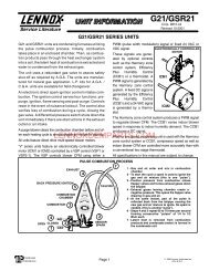
G61MPV PARTS ARRANGEMENTTOP CAPDuralokPlus TMHEAT EXCHANGERASSEMBLYCABINETBURNER BOXASSEMBLYGAS VALVEAND MANIFOLDFLUECOLLARCOMBUSTIONAIR PRESSURE PROVESWITCHES(36B−045 has 2 single switches)COMBUSTION AIRINDUCERBURNERACCESSPANELCOLD HEADER(COLLECTOR)BOXWARM HEADER(COLLECTOR)BOXCONDENSER COILPRIMARY LIMITBLOWERACCESSPANELSIGHTGLASSSECONDARYLIMITS (2)DOORINTERLOCKSWITCHCONTROL BOXPower Choke(5 Ton Only)CIRCUIT BREAKERBlower MotorFIGURE 1Page 23
I−UNIT COMPONENTSG61MPV unit components are shown in figure 1. The gasvalve, combustion air inducer <strong>and</strong> burners can be accessedby removing the burner access panel. Electricalcomponents are in the control box (figure 2) found in theblower section.G61MPV units are factory equipped with a bottom return airpanel in place. The panel is designed to be field removed asrequired for bottom air return. Markings are provided for sidereturn air <strong>and</strong> may be cut out in the field.ELECTROSTATIC DISCHARGE (ESD)Precautions <strong>and</strong> ProceduresCAUTIONElectrostatic discharge can affect electroniccomponents. Take precautions during furnaceinstallation <strong>and</strong> <strong>service</strong> to protect the furnace’selectronic controls. Precautions will help to avoidcontrol exposure to electrostatic discharge byputting the furnace, the control <strong>and</strong> the technicianat the same electrostatic potential. Neutralizeelectrostatic charge by touching h<strong>and</strong> <strong>and</strong> alltools on an unpainted unit surface, such as thegas valve or blower deck, before performing any<strong>service</strong> procedure.A−Control Box1. Control Transformer (T1)A transformer located in the control box provides power tothe low voltage section of the unit. Transformers on allmodels are rated 40VA with a 120V primary <strong>and</strong> a 24V secondary.2. Door Interlock Switch (S51)A door interlock switch rated 14A at 125VAC is wired in serieswith line voltage. When the blower door is removed theunit will shut down.CONTROL BOX G61MPV3. Circuit Breaker (CB8)A 24V circuit breaker is also located in the control box.The switch provides overcurrent protection to the transformer(T1). The breaker is rated 3A at 32V. If the currentexceeds this limit the breaker will trip <strong>and</strong> all unit operationwill shutdown. The breaker can be <strong>manual</strong>ly resetby pressing the button on the face. See figure 3.CIRCUIT BREAKER CB8PRESS TO RESETFIGURE 3WARNINGShock hazard.Disconnect power before servicing. IntegratedControl Board is not field repairable. If control isinoperable, simply replace entire control.Can cause injury or death. Unsafe operation willresult if repair is attempted.4. Integrated Control Board (A92)SureLight Board 49M59G61MPV units are equipped with the Lennox two−stage,variable speed integrated SureLight® control. The systemconsists of a ignition / blower control (figure 4 withcontrol terminal designations in tables 1 through 4) <strong>and</strong> ignitor(figure 12). The control <strong>and</strong> ignitor work in combinationto ensure furnace ignition <strong>and</strong> ignitor durability. TheSureLight integrated board controls all major furnace operations.The control features two LED lights, (DS1 <strong>and</strong>DS2) for troubleshooting <strong>and</strong> four LED lights (DS3, DS6,DS7 <strong>and</strong> DS8) to show furnace status. The control alsohas two accessory terminals rated at (1) one amp each.See table 5 for status code <strong>and</strong> table 6 for troubleshootingdiagnostic codes.DOOR INTERLOCKSWITCHSURELIGHT®CONTROLBOARDFIGURE 2CIRCUITBREAKERTRANSFORMERElectronic IgnitionAt the beginning of the heat cycle the SureLight controlmonitors the first stage <strong>and</strong> second stage combustion airinducer prove switch. The control will not begin the heatingcycle if the first stage or second stage prove switch isclosed (jumpered). Likewise the control will not begin thesecond stage heating cycle if the second stage proveswitch is closed, <strong>and</strong> will remain in first stage heat. However,if the second stage prove switch closes during the firststage heat pre−purge, the control will allow second stageheat. Once the first stage prove switch is determined to beopen, the combustion air inducer is energized on low (firststage) heat speed. When the differential in the prove switchis great enough, the prove switch closes <strong>and</strong> a 15−secondpre−purge begins. If the switch is not proven within 2−1/2minutes, the control goes into Watchguard−PressureSwitch mode for a 5−minute re−set period.Page 24
After the 15−second pre−purge period, the SureLight ignitorwarms up for 20 seconds after which the gas valve opensfor a 4−second trial for ignition. The ignitor energizes duringthe trial until flame is sensed. If ignition is not proved duringthe 4−second period, the control will try four more times withan inter−purge <strong>and</strong> warm−up time between trials of 35 seconds.After a total of five trials for ignition (including the initialtrial), the control goes into Watchguard mode. After a60−minute reset period, the control will begin the ignitionsequence again.The SureLight control has an added feature that prolongsthe life of the ignitor. After a successful ignition, the SureLightcontrol utilizes less power to energize the ignitor onsuccessive calls for heat. The control continues to rampdown the voltage to the ignitor until it finds the lowestamount of power that will provide a successful ignition. Thisamount of power is used for 255 cycles. On the 256th callfor heat, the control will again ramp down until the lowestpower is determined <strong>and</strong> the cycle begins again.Two Stage Operation / Thermostat Selection JumperThe control can be utilized in two modes: SINGLE−STAGEthermostat or TWO−STAGE thermostat. The thermostatselection jumper E20, located just below dip switches 1through 3 (figure 4), must be positioned for the particularapplication. The jumper is factory set on TWO" for usewith a two−stage thermostat with two stage heat. Re−positionjumper to SINGLE" for use with a single stage thermostatwith two stage heat.While in the single−stage thermostat mode (single jumpersetting), the burners will always fire on first−stage heat. Thecombustion air inducer will operate on low speed <strong>and</strong> indoorblower will operate on low heat speed. After a 10 minuterecognition period, the unit will switch to second stageheat. While in the two−stage thermostat mode (two jumpersetting) the burners will fire on first−stage heat. The combustionair inducer will operate on low speed <strong>and</strong> indoorblower will operate on low heat speed. The unit will switchto second−stage heat on call from the indoor thermostat. Ifthere is a simultaneous call for first <strong>and</strong> second stage heat,the unit will fire an first stage heat <strong>and</strong> switch to secondstage heat after 30 seconds of operation. See Sequence ofOperation flow charts in the back of this <strong>manual</strong> for moredetail.TWO−STAGE, VARIABLE SPEED INTEGRATEDCONTROL BOARDLEDsON−BOARDJUMPER W914(cut when SignatureStat,CCB1 or Harmony II areused)ON−BOARDJUMPER W915(cut when two−stagecooling is used)FIGURE 4DIAGNOSTICLEDsDIPSWITCHES1 − 3DIPSWITCHES5 − 12LEDON−BOARDJUMPER W951(cut when heat pump isused with FM21)THERMOSTAT CONNECTIONS (TB1)DIP SWITCH FUNCTIONSDIP SWITCH(ES)FUNCTION1 <strong>and</strong> 2 Blower Off Delay3 Second Stage ON Delay (Single−stage t’stat)4 Not used5 <strong>and</strong> 6 Cooling Mode Blower Speed7 <strong>and</strong> 8 Blower Speed Adjustment9 <strong>and</strong> 10 Cooling Mode Blower Ramping Profile11 <strong>and</strong> 12 <strong>Heating</strong> Mode Blower SpeedPage 25
TABLE 1SureLight Control / Blower Control TerminalsLINELine 120VAC NeutralXFMRTransformer 120VAC NeutralEACElectronic <strong>Air</strong> Cleaner 120VAC NeutralCIRCIndoor Blower 120VAC NeutralHUMHumidifier 120VAC NeutralHUMHumidifier 120VAC HotXMFRTransformer 120VAC HotLINELine 120VAC HotCIRCIndoor Blower 120VAC HotEACElectronic <strong>Air</strong> Cleaner 120VAC HotTABLE 2SureLight Control 5 Pin Terminal DesignationPIN #Function1 Ignitor2 Combustion <strong>Air</strong> Inducer High Speed3 Combustion <strong>Air</strong> Inducer Low Speed4 Combustion <strong>Air</strong> Inducer Neutral5 Ignitor NeutralTABLE 3SureLight Control 12Pin Terminal DesignationPIN #Function1 Gas Valve High Fire2 Second Stage Pressure Switch3 Not Used4 Ground5 24V Hot6 Primary Limit In7 Gas Valve Low Stage8 Gas Valve Common9 24V Neutral10 Ground11 Primary Limit Out12 1st Stage Pressure SwitchTABLE 4SureLight Control 16 Pin Blower Control TerminalsPIN #Function1 Ground2 Low Heat Speed3 Ground4 DELAY" Dip Switch Selection5 COOL" Dip Switch Selection6 Y1" Signal7 ADJUST" Dip Switch Selection8 Ground9 0" From Thermostat10 DS" Output Signal11 HEAT" Dip Switch Selection12 24 VAC13 HIGH HEAT Speed14 Y2" Signal15 G"16 CFM LEDPage 26
TABLE 5STATUS CODESSTATUS LED COLOR FUNCTIONDS3ON / OFF ’DS6CFM"DS7HI / LO"DS8HEAT"GREENGREENYELLOWYELLOWDS3−ON indicates that the motor has a dem<strong>and</strong> to operate. (This LED must be on in allmodes).DS6−blinking indicates the airflow (CFM) dem<strong>and</strong> in the motor. The air flow is determine bycounting blinks between two (2) second pauses. One blink equals approximatley 100 CFM.DS7−ON indicaties the DS to R" jumper has not been cut. When the jumper is cut the systemwill be operating with LENNOX HARMONY II (See Harmony Installation Instructions) orwith the CCB1 Efficiency Plus control.CCB1: When ON, a 24 VAC is being applied <strong>and</strong> when OFF, it has been removed. This on/offoperation varies the indoor blower’s performance so dehumidification can be enhanced.DS8−ON indicates the system is in HEAT mode.TABLE 6DIAGNOSTIC CODESDiagnostic LEDs are labeled DS1 <strong>and</strong> DS2. See figure 4 for location of diagnostic LEDs.DS1 DS2 DESCRIPTIONSIMULTANEOUSSLOW FLASHSIMULTANEOUSFAST FLASHSIMULTANEOUSSLOW FLASHSIMULTANEOUSFAST FLASHPower on − Normal operation.Also signaled during cooling <strong>and</strong> continuous fan.Normal operation − signaled when heating dem<strong>and</strong> initiated at thermostat.SLOW FLASH ON Primary, secondary, backup secondary or rollout limit switch open. Limits mustclose within 3 minutes or unit goes into 1 hour Watchguard.Low prove switch open;OFFSLOW FLASH OR: Blocked inlet/exhaust vent;OR: Low prove switch closed prior to activation of combustion air inducer.OFFALTERNATINGSLOW FLASHFAST FLASHALTERNATINGSLOW FLASHHigh prove switch open;OR: Blocked inlet/exhaust vent;OR: High prove switch closed prior to activation of combustion air inducer.Watchguard −− burners failed to ignite; OR limit open more than 3 minutes;OR lost flame sense 5 times in one heating cycle;OR pressure switch opened 5 times in one heating cycle.SLOW FLASH OFF Flame sensed without gas valve energized.ONONOFFONOFFONCircuit board failure or control wired incorrectly. Check 24 <strong>and</strong> 115 volts to board.FAST FLASH SLOW FLASH Main power polarity reversed. Switch line <strong>and</strong> neutral.SLOW FLASH FAST FLASH Low flame signal. Measures below 0.23 microAmps. Replace flame sense rod.ALTERNATINGFAST FLASHALTERNATINGFAST FLASHThe following conditions are sensed during the ignitor warm−up period only:1) Improper main ground;2) Broken ignitor; OR: Open ignitor circuit;3) Line voltage below 75 volts.(If voltage lower than 75 volts prior to ignitor warm-up, control will signal waiting oncall from thermostat, <strong>and</strong> will not respond.NOTE − Slow flash rate equals 1 Hz (one flash per second). Fast flash rate equals 3 Hz (three flashes per second).Low flame sense current = 0.17−0.22 microAmps.Page 27
Dip Switch SettingsSwitches 1 <strong>and</strong> 2 −− Blower Off Delay −− The blower−ondelay of 45 seconds is not adjustable. The blower−off delay(time that the blower operates after the heating dem<strong>and</strong>has been satisfied) can be adjusted by moving switches 1<strong>and</strong> 2 on the integrated control board. The unit is shippedfrom the factory with a blower−off delay of 90 seconds. Theblower off delay affects comfort <strong>and</strong> is adjustable to satisfyindividual applications. Adjust the blower off delay toachieve a high fire supply air temperature between 90° <strong>and</strong>110°F at the exact moment that the blower is de−energized.Longer off delay settings provide lower supply air temperatures;shorter settings provide higher supply air temperatures.The table below provides the blower off timings thatwill result from different switch settings.TABLE 7Blower Off Delay Switch SettingsBlower Off DelaySwitch 1 Switch 2(Seconds)60 Off Off90 Off On120 On Off180 On OnSwitch 3 −− Second Stage Delay (Used with Single−Stage Thermostat Only) −− This switch is used to determinethe second stage on delay when a single−stage thermostatis being used. The switch is factory−set in the ONposition, which provides a 10−minute delay before second−stage heat is initiated. If the switch is toggled to the OFFposition, it will provide a 15−minute delay before second−stage heat is initiated. This switch is only activated whenthe E20 thermostat selector jumper is positioned forSINGLE−stage thermostat use.Switch 4 −− Not used in G61MPV application.Switches 5 <strong>and</strong> 6 −− Cooling Mode Blower Speed −−Switches 5 <strong>and</strong> 6 are used to select second stage coolingblower motor speed (first stage cooling speed is 70% ofsecond stage). The unit is shipped from the factory with thedip switches positioned for high speed (4) indoor blowermotor operation during the cooling mode. The table belowprovides the cooling mode blower speeds that will resultfrom different switch settings. Refer to blower data tables atthe front of this <strong>manual</strong> for corresponding cfm values.TABLE 8Cooling Mode Blower SpeedsSpeed Switch 5 Switch 61 − Low On On2 − Medium Low Off On3 − Medium High On Off4 − High (Factory) Off OffSwitches 7 <strong>and</strong> 8 −− Blower Speed Adjustment −−Switches 7 <strong>and</strong> 8 are used to select blower speed adjustmentsettings. The unit is shipped from the factory with thedip switches positioned for NORMAL (no) adjustment. Thedip switches may be positioned to adjust the blower speedby +10% or −10% to better suit the application. The tablebelow provides blower speed adjustments that will resultfrom different switch settings. Refer to blower data tables atthe front of this <strong>manual</strong> for corresponding cfm values.TABLE 9Blower Speed AdjustmentAdjustment Switch 7 Switch 8+10% (approx.) On OffNORMAL (Factory) Off Off−10% (approx.) Off OnSwitches 9 <strong>and</strong> 10 −− Cooling Mode Blower SpeedRamping −− Switches 9 <strong>and</strong> 10 are used to select coolingmode blower speed ramping options. Blower speed rampingmay be used to enhance dehumidification performance.The switches are factory set at option A which hasthe greatest effect on blower motor performance. The tablebelow provides the cooling mode blower speed rampingoptions that will result from different switch settings. Thecooling mode blower speed ramping options are detailedbelow.TABLE 10Cooling Mode Blower Speed RampingRamping Option Switch 9 Switch 10A (Factory) Off OffB On OffC Off OnD On OnOFFOFFCOOLING MODE RAMPING OPTIONSRamping Option A (Factory Selection)Motor runs at 50% for 30 seconds.Motor then runs at 82% for approximately 7−1/2 minutes.If dem<strong>and</strong> has not been satisfied after 7−1/2 minutes,motor runs at 100% until dem<strong>and</strong> is satisfied.Once dem<strong>and</strong> is met, motor runs at 50% for 30 secondsthen ramps down to stop.1/2 MIN50% CFM7 1/2 MIN82% CFMCOOLING DEMAND100%CFM1/2 MIN50% CFMOFFRamping Option BMotor runs at 82% for approximately 7−1/2 minutes. Ifdem<strong>and</strong> has not been satisfied after 7−1/2 minutes,motor runs at 100% until dem<strong>and</strong> is satisfied.Once dem<strong>and</strong> is met, motor ramps down to stop.7 1/2 MIN82%CFMCOOLING DEMAND100% CFMOFFPage 28
OFFRamping Option CMotor runs at 100% until dem<strong>and</strong> is satisfied.Once dem<strong>and</strong> is met, motor runs at 100% for 60 secondsthen ramps down to stop.100% CFM 100% CFMDEMAND60 SEC.Ramping Option D Motor runs at 100% until dem<strong>and</strong> is satisfied.Once dem<strong>and</strong> is met, motor ramps down to stop.OFF100% CFMCOOLINGDEMANDOFFOFFSwitches 11 <strong>and</strong> 12 −− <strong>Heating</strong> Mode Blower Speed −−Switches 11 <strong>and</strong> 12 are used to select second stage heatingmode blower motor speed (first stage heating blowerspeed is 91% of second stage). The unit is shipped from thefactory with the dip switches positioned for medium low (2)speed indoor blower motor operation during the heatingmode. The table below provides the heating mode blowerspeeds that will result from different switch settings. Referto blower data tables at the front of this <strong>manual</strong> for correspondingcfm values.TABLE 11<strong>Heating</strong> Mode Blower SpeedsSpeed Switch 11 Switch 121 − Low On On2 − Medium Low(Factory)OffOn3 − Medium High On Off4 − High Off OffOn−Board Jumper W914On−board jumper W914, which connects terminals DS <strong>and</strong>R on the integrated control board, must be cut when the furnaceis installed with the Harmony II zone control board,the CCB1 EfficiencyPlus humidity control or the LennoxSignatureStat. If the jumper is left intact the PMW signalfrom the Harmony II control will be blocked <strong>and</strong> also lead tocontrol damage. The SignatureStat <strong>and</strong> CCB1 will not operateunless the jumper is cut. Refer to table 21 for operationsequence in applications including a G61MPV, CCB1<strong>and</strong> single−speed outdoor unit. Table 22 gives the operationsequence in applications with a two−speed outdoorunit. See table 23 for applications for a G61MVP, SignatureStat<strong>and</strong> single−speed outdoor unit <strong>and</strong> table 24 for applicationswith a two−speed outdoor unit.On−Board Jumper W951On−board jumper W951, which connects terminals R <strong>and</strong> Oon the integrated control board, must be cut when the furnaceis installed in applications which include a heat pumpunit <strong>and</strong> the FM21 FuelMaster control board. If the jumperis left intact, terminal "O" will remain energized eliminatingthe HEAT MODE in the heat pump.On−Board Jumper W915On−board jumper W915, which connects terminals Y1 <strong>and</strong>Y2 on the integrated control board, must be cut if two−stagecooling will be used. If the jumper is not cut the outdoor unitwill operate in first−stage cooling only.Diagnostic LEDs (DS1 <strong>and</strong> DS2)Two diagnostic LEDs are located on the two−stage, variablespeed integrated control just to the left of the first bankof dip switches. These flashing lights correspond with diagnosticcodes detailed on page 52.Status LEDs (HEAT, HI/LO, ON/OFF <strong>and</strong> CFM)The integrated control includes four LEDs which indicateoperating status. The green ON/OFF LED is lit any time theblower is operating. The green CFM LED indicates theblower motor speed. Count the number of blinks betweenthe two−second pauses to determine the CFM. Each blinkrepresents approximately 100 CFM. The yellow HI/LO LEDis lit when the W914 (DS to R) jumper has not been clippedfor SignatuteStat, CCB1 or Harmony operation. The yellowHEAT LED is lit when the indoor blower is operating at theHEATING speed.Page 29
WARNINGShock hazard.Disconnect power before servicing. IntegratedControl Board is not field repairable. If control isinoperable, simply replace entire control.Can cause injury or death. Unsafe operation willresult if repair is attempted.5. Integrated Control Board(A92)SureLight Board 100870G61MPV −7 <strong>and</strong> later units are equipped with the Lennoxtwo−stage, variable speed integrated SureLight controlboard. The system consists of a ignition / blower controlboard (figures 5 <strong>and</strong> 6) with control pin designations intables 12, 13 <strong>and</strong> 14 <strong>and</strong> ignitor (figure 13). The board <strong>and</strong>ignitor work in combination to ensure furnace ignition <strong>and</strong>ignitor durability. The SureLight integrated board controlsall major furnace operations. The board features a red LEDlight, for furnace status <strong>and</strong> troubleshooting. The LEDflashes in X" + Y" codes. For example using table 15 underPRESSURE SWITCH CODES", if the red LEDflashes 2 times, then off for 2 seconds then flashes 3times, the low pressure switch is failed open. Two greenLEDs show indoor blower status <strong>and</strong> CFM. See Page 35for more detail. The board also has two 120 volt accessoryterminals rated at (1) one amp each. In addition there isa 24 volt accessory terminal located on TB1.Electronic IgnitionAt the beginning of the heat cycle the SureLight controlmonitors the first stage <strong>and</strong> second stage combustion airinducer prove switch. The control will not begin the heatingcycle if the first stage prove switch is closed (by−passed).Likewise the control will not begin the second stage heatingcycle if the second stage prove switch is closed, <strong>and</strong> will remainin first stage heat. However, if the second stage proveswitch closes during the first stage heat pre−purge, the controlwill allow second stage heat. Once the first stage proveswitch is determined to be open, the combustion air induceris energized on low (first stage) heat speed. When thedifferential in the prove switch is great enough, the proveswitch closes <strong>and</strong> a 15−second pre−purge begins. If theswitch is not proven within 2−1/2 minutes, the control goesinto Watchguard−Pressure Switch mode for a 5−minute re−set period.After the 15−second pre−purge period, the SureLight ignitorwarms up for 20 seconds after which the gas valve opensfor a 4−second trial for ignition. The ignitor energizes duringthe trial until flame is sensed. If ignition is not proved duringthe 4−second period, the control will try four more times withan inter purge <strong>and</strong> warm−up time between trials of 35 seconds.After a total of five trials for ignition (including the initialtrial), the control goes into Watchguard−Flame Failuremode. After a 60−minute reset period, the control will beginthe ignition sequence again.NOTE − Board 100870 provides a regulated 95 voltsthe ignitor.Two Stage Operation / Thermostat Selection JumperThe control can be utilized in two modes: SINGLE−STAGEthermostat or TWO−STAGE thermostat. The thermostatselection is made using a dip switch (figure 4) <strong>and</strong> must bepositioned for the particular application. The dip switch isfactory set on TWO" for use with a two−stage thermostatwith two stage heat. Re−position dip switch to SINGLE" foruse with a single stage thermostat with two stage heat.While in the single−stage thermostat mode (single dipswitch setting), the burners will always fire on first−stageheat. The combustion air inducer will operate on low speed<strong>and</strong> indoor blower will operate on low heat speed. After afactory default 10 minute recognition period, the unit willswitch to second stage heat. While in the two−stage thermostatmode (two dip switch setting) the burners will fire onfirst−stage heat. The combustion air inducer will operate onlow speed <strong>and</strong> indoor blower will operate on low heatspeed. The unit will switch to second−stage heat on callfrom the indoor thermostat. If there is a simultaneous callfor first <strong>and</strong> second stage heat, the unit will fire an first stageheat <strong>and</strong> switch to second stage heat after 30 seconds ofoperation. See Sequence of Operation flow charts in theback of this <strong>manual</strong> for more detail.Page 30
TWO−STAGE, VARIABLE SPEED INTEGRATED CONTROL BOARD1/4" QUICK CONNECT TERMINALSNEUTRALS= 120 VAC NEUTRALON19THERMOSTAT CONNECTIONS (TB1)12ONDIAGNOSTICLEDs58161 4HEATINGDIPSWITCHESINDOORBLOWER DIPSWITCHESFUTURE USEON−BOARDLINKSH= 24V HUMIDIFIER OUTPUTL= LENNOX SYSTEM OPERATION MONITOR1= FUTURE USEDIP SWITCH FUNCTIONSHTG DIP SWITCH(ES)FUNCTIONW915W951W9141 T’stat Heat Stages (single or two−stage)2 Second Stage ON Delay (single−stage t’stat)3 <strong>and</strong> 4 <strong>Heating</strong> Fan OFF DelayINDOOR BLOWERFUNCTIONDIP SWITCH(ES)5 <strong>and</strong> 6 Cooling Mode Blower Speed7 <strong>and</strong> 8 Blower Speed Adjustment9 <strong>and</strong> 10 Cooling Mode Blower Ramping Profile11 <strong>and</strong> 12 <strong>Heating</strong> Mode Blower SpeedFIGURE 5TABLE 12SureLight Board 5 Pin Terminal DesignationPIN #Function1 Ignitor2 Combustion <strong>Air</strong> Inducer High Speed3 Combustion <strong>Air</strong> Inducer Low Speed4 Combustion <strong>Air</strong> Inducer Neutral5 Ignitor NeutralTABLE 13SureLight Board 12Pin Terminal DesignationPIN #Function1 Gas Valve High Fire2 Second Stage Prove Switch3 Rollout In4 Ground5 24V Hot6 Primary Limit In7 Gas Valve Low Stage8 Gas Valve Common9 24V Neutral10 Ground11 Rollout Switch Out12 1st Stage Prove SwitchTABLE 14SureLight Board 16 Pin Blower Control TerminalsPIN #Function1 Ground2 Low Heat Speed3 Ground4 DELAY" Dip Switch Selection5 COOL" Dip Switch Selection6 Y1" Signal7 ADJUST" Dip Switch Selection8 Ground9 0" From Thermostat10 DS" Output Signal11 HEAT" Dip Switch Selection12 24 VAC13 HIGH HEAT Speed14 Y2" Signal15 G"16 CFM LEDPage 31
FIGURE 6Page 32
FLASH CODE(X + Y)PulseHeartbeatX + YPulseHeartbeatTABLE 15STATUS / ERROR DESCRIPTIONFLASH CODE DESCRIPTIONSA 1/4 second flash followed by four seconds of off time.Constant 1/2 second bright <strong>and</strong> 1/2 second dim cycles.LED flashes X times at 2Hz, remains off for two seconds, flashes Y times at 2Hz, remains off for fourseconds, then repeats.Power on − St<strong>and</strong>by.Normal operation − signaled when heating dem<strong>and</strong> initiated at thermostat.FLAME CODES1 + 2 Low flame current −− run mode.1 + 3 Flame sensed out of sequence −− flame still present.PRESSURE SWITCH CODES2 + 3 Low pressure switch failed open.2 + 4 Low pressure switch failed closed.2 + 5 High pressure switch failed open.2 + 6 High pressure switch failed closed.2 + 7 Low pressure switch opened during ignition trial or heating dem<strong>and</strong>.LIMIT CODE3 + 1 Limit switch open.WATCHGUARD CODES4 + 1 Watchguard −− Exceeded maximum number of retries.4 + 2 Watchguard −− Exceeded maximum number of retries or last retry was due to pressure switch opening.4 + 3 Watchguard −− Exceeded maximum number of retries or last retry was due to flame failure.4 + 5 Watchguard −− Limit remained open longer than three minutes.4 + 6 Watchguard −− Flame sensed out of sequence; flame signal gone.4 + 7 Ignitor circuit fault −− Failed ignitor or triggering circuitry.4 + 8 Low line voltage.HARD LOCKOUT CODES5 + 1 Hard lockout −− Rollout circuit open or previously opened.5 + 2 Control failed self check, internal error (control will restart if error recovers).5 + 3 No Earth ground (control will restart if error recovers).5 + 4 Reversed line voltage polarity (control will restart if the error recovers).5 + 6 Low secondary (24VAC) voltage.Error Code StorageThe ignition control stores the last ten error codes inmemory. The codes are retained in case of power loss.Error Code Review1 − Short R (2) to (1). Within 1/2 second, the STATUS LEDwill stay lit continuously to indicate that the short wassensed.2 − Continue to hold the short between R (2) to (1). After 5seconds, STATUS LED will go from being continuouslylit to off. This indicates that error code review ispending.3 − Remove R (2) to (1) short within ten seconds of STA-TUS LED turning off. This activates error code review.4 − Last ten error codes will be flashed on the STATUSLED.5 − After final error code is indicated, STATUS LED willflash to indicate normal operation.Clearing Error Codes1 − Short R (2) to (1). Within 1/2 second, the STATUS LEDwill stay lit continuously to indicate that the short wassensed.2 − Continue to hold the short between R (2) to (1). After 5seconds, STATUS LED will go from being continuouslylit to off.3 − Continue to hold the short between R (2) to (1) beyondten seconds after STATUS LED has turned off.STATUS LED will turn on, indicating that error codeshave been cleared.4 − Remove R (2) to (1) short. STATUS LED will flash toindicate normal operation.Page 33
Dip Switch Settings<strong>Heating</strong> Operation DIP Switch SettingsSwitch 1 −− Thermostat Selection −− This unit may be usedwith either a single−stage or two−stage thermostat. Thethermostat selection is made using a DIP switch whichmust be properly positioned for the particular application.The Dip switch is factory−positioned for use with a two−stage thermostat. If a single−stage thermostat is to be used,the DIP switch must be repositioned.a − Select OFF" for two−stage heating operation controlledby a two−stage heating thermostat (factory setting);b − Select ON" for two−stage heating operation controlledby a single−stage heating thermostat. This settingprovides a timed delay before second−stage heatis initiated.Switch 2 −− Second Stage Delay (Used with Single−Stage Thermostat Only) −− This switch is used to determinethe second stage on delay when a single−stage thermostatis being used. The switch is factory−set in the OFFposition, which provides a 10−minute delay before second−stage heat is initiated. If the switch is toggled to the ONposition, it will provide a 15−minute delay before second−stage heat is initiated. This switch is only activated whenthe thermostat selector jumper is positioned for SINGLE−stage thermostat use.Switches 3 <strong>and</strong> 4 −− Blower−Off Delay −− The blower−ondelay of 45 seconds is not adjustable. The blower−off delay(time that the blower operates after the heating dem<strong>and</strong>has been satisfied) can be adjusted by moving switches 3<strong>and</strong> 4 on the integrated control board. The unit is shippedfrom the factory with a blower−off delay of 90 seconds. Theblower off delay affects comfort <strong>and</strong> is adjustable to satisfyindividual applications. Adjust the blower off delay toachieve a supply air temperature between 90° <strong>and</strong> 110°F atthe exact moment that the blower is de−energized. Longeroff delay settings provide lower supply air temperatures;shorter settings provide higher supply air temperatures.Table16 provides the blower off timings that will resultfrom different switch settings.TABLE 16Blower Off Delay Switch SettingsBlower Off DelaySwitch 3 Switch 4(Seconds)60 Off On90 Off Off120 On Off180 On OnIndoor Blower Operation DIP Switch SettingsSwitches 5 <strong>and</strong> 6 −− Cooling Mode Blower Speed −−Switches 5 <strong>and</strong> 6 are used to select cooling blower motorspeed. The unit is shipped from the factory with the DIPswitches positioned for high speed (4) indoor blower motoroperation during the cooling mode. The table below providesthe cooling mode blower speeds that will result fromdifferent switch settings. Refer to blower tables at the frontof this <strong>manual</strong> for corresponding cfm values.TABLE 17Cooling Mode Blower SpeedsSpeed Switch 5 Switch 61 − Low On On2 − Medium Low Off On3 − Medium High On Off4 − High (Factory) Off OffSwitches 7 <strong>and</strong> 8 −− Blower Speed Adjustment −−Switches 7 <strong>and</strong> 8 are used to select blower speed adjustmentsettings. The unit is shipped from the factory with theDIP switches positioned for NORMAL (no) adjustment.The DIP switches may be positioned to adjust the blowerspeed by +10% or −10% to better suit the application. Thetable below provides blower speed adjustments that will resultfrom different switch settings. Refer to blower tables atthe front of this <strong>manual</strong> for corresponding cfm values.TABLE 18Blower Speed AdjustmentAdjustment Switch 7 Switch 8+10% (approx.) On OffNORMAL (Factory) Off Off−10% (approx.) Off OnSwitches 9 <strong>and</strong> 10 −− Cooling Mode Blower SpeedRamping −− Switches 9 <strong>and</strong> 10 are used to select coolingmode blower speed ramping options. Blower speed rampingmay be used to enhance dehumidification performance.The switches are factory set at option A which hasthe greatest effect on blower motor performance. Table 19provides the cooling mode blower speed ramping optionsthat will result from different switch settings. The coolingmode blower speed ramping options are detailed onPage 28.NOTE − The off portion of the selected ramp profile also appliesduring heat pump operation in dual fuel applications.TABLE 19Cooling Mode Blower Speed RampingRamping Option Switch 9 Switch 10A (Factory) Off OffB On OffC Off OnD On OnSwitches 11 <strong>and</strong> 12 −− <strong>Heating</strong> Mode Blower Speed −−Switches 11 <strong>and</strong> 12 are used to select heating mode blowermotor speed. The unit is shipped from the factory with thedip switches positioned for medium low (2) speed indoorblower motor operation during the heating mode. The tablebelow provides the heating mode blower speeds that willresult from different switch settings. Refer to blower tablesat the front of this <strong>manual</strong> for corresponding cfm values.Page 34
TABLE 20<strong>Heating</strong> Mode Blower SpeedsSpeed Switch 11 Switch 121 − Low On On2 − Medium Low(Factory)OffOn3 − Medium High On Off4 − High Off OffOn−Board Link W914On−board link W914 is a clippable connection which connectsterminals DS <strong>and</strong> R on the integrated control board.W914 must be cut when the furnace is installed with eitherthe Harmony III zone control board or a thermostat whichfeatures humidity control. If the link is left intact the PWMsignal from the HARMONY III control will be blocked <strong>and</strong>also lead to control damage. Refer to table 21 (CCB1) <strong>and</strong>table 23 (SignatureStat) for operation sequence in applicationsincluding G60DFV, a thermostat which featureshumidity control <strong>and</strong> a single−speed outdoor unit. Table 22(CCB1) <strong>and</strong> table 24 (SignatureStat) gives the operationsequence in applications with a two−speed outdoor unit.On−Board Link W951On−board link W951 is a clippable connection which connectsterminals R <strong>and</strong> O on the integrated control board.W951 must be cut when the furnace is installed in applicationswhich include a heat pump unit <strong>and</strong> a thermostatwhich features dual fuel use. If the link is left intact, terminalO" will remain energized eliminating the HEAT MODE inthe heat pump.On−Board Link W915On−board link W915 is a clippable connection which connectsterminals Y1 <strong>and</strong> Y2 on the integrated control board.W915 must be cut if two−stage cooling will be used. If thelink is not cut the outdoor unit will operate in second stagecooling only.Status LEDs (SPEED, CFM, E−COM)The green SPEED LED indicates circulating blower speedin response to the DS signal. The LED is lit during normalblower operation <strong>and</strong> is off during a dehumidification dem<strong>and</strong>.In Harmony III applications, the brightness of theLED indicates the requested blower speed.The green CFM LED indicates the blower air flow. Countthe number of blinks between the two−second pauses todetermine the CFM. Each blink represents approximately100 CFM.The green E−COM LED indicates that the control is receiving<strong>and</strong> processing of comm<strong>and</strong>s <strong>and</strong> inputs. The LED mayflash rapidly or may display a single flash, depending uponthe activity.TABLE 21G61MPV, CCB1 <strong>and</strong> Single−Speed Outdoor UnitOPERATING MODE SYSTEM DEMAND SYSTEM RESPONSESystem ConditionThermostatDem<strong>and</strong>*Relative Humidity(EfficiencyPlus Lights)Blower CFM(COOL)CommentsNormal operation*Call for humidityremoval duringcooling dem<strong>and</strong>Dehumidificationdem<strong>and</strong> satisfiedduring cooling dem<strong>and</strong>.Call for cooling after call forhumidityremoval.Humidity dem<strong>and</strong>satisfied betweenthermostat dem<strong>and</strong>s (unitoff cycle).Y1Y1Y1NoneY1No dem<strong>and</strong>. Humiditylevel is acceptableHumidity level rises abovesetpoint. Dem<strong>and</strong> initiated.Humidity level falls below setpoint.No dem<strong>and</strong>Humidity level above setpoint.Dem<strong>and</strong> initiated.Humidity level above setpoint.Dem<strong>and</strong> initiated.COOL70%of COOLCOOLOff70%of COOLCompressor dem<strong>and</strong> <strong>and</strong> indoor blower speedcontrolled by thermostat dem<strong>and</strong>.Call for dehumidification initiated by CCB1 control.Indoor blower speed reduced by CCB1 control.When humidity dem<strong>and</strong> is satisfied, blower speedimmediately increases to the COOL CFM to hastenthe end of the cycle.Dehumidification mode begins when relative humidityis greater than setpoint.None Over setpoint (1 or more) Off While unit is not operating (no thermostat dem<strong>and</strong>),slide switch is moved down <strong>and</strong> back up.Y1 Change to acceptable COOL Blower operates at COOL CFM.NOTE − When changing unit mode of operation from cooling to heating, indicating lights that are on will stay on until the first thermostat heatingdem<strong>and</strong>.* Reduced blower speed is 70% of COOLPage 35
TABLE 22OPERATING SEQUENCEG61MPV, CCB1 <strong>and</strong> Two−Speed Outdoor UnitOPERATING MODE SYSTEM DEMAND SYSTEM RESPONSESystemConditionThermostatDem<strong>and</strong>*Relative Humidity(EfficiencyPlus Lights)****CompressorSpeedBlower CFM(COOL)CommentsNormal operationCall for humidityremoval during1st−stage coolingdem<strong>and</strong>Significant increase inhumidity duringthermostat coolingdem<strong>and</strong>.Humidity dem<strong>and</strong>satisfied duringthermostat dem<strong>and</strong>.Call for humidityremoval during 2ndstage thermostatdem<strong>and</strong>*Call for 1st stagecooling after call forhumidity removal.Call for 2nd stagecooling after call forhumidity removalCall for cooling aftersignificant increase inhumidityHumidity dem<strong>and</strong>satisfied betweenthermostat dem<strong>and</strong>s(unit off cycle).Y1 No dem<strong>and</strong>. Acceptable Low**49% of HIGHCOOLY2 No dem<strong>and</strong>. Acceptable High HIGH COOLY1 No dem<strong>and</strong>. Acceptable Low**49% of HIGHCOOLY1Dem<strong>and</strong>satisfiedY1Humidity level rises slightly(1) above setpoint. Dem<strong>and</strong>initiated.Humidity level remainsslightly (1) above setpoint.Dem<strong>and</strong> continues.Humidity level remainsslightly (1) above setpoint.Dem<strong>and</strong> continues.LowOffHighY1 No dem<strong>and</strong>. Acceptable LowY1Y1Y1Humidity level rises significantly(2 or more) abovesetpoint. Dem<strong>and</strong> initiated.Humidity levelabove setpoint.Humidity level falls belowsetpoint. No dem<strong>and</strong>.HighHighHigh**49% of HIGHCOOLOff***70%ofHIGH COOL**49% of HIGHCOOL***70% ofHIGH COOL***70% ofHIGH COOLHIGH COOLNone No dem<strong>and</strong>. Acceptable Off OffY1 No dem<strong>and</strong>. Acceptable Low**49% of HIGHCOOLY2 No dem<strong>and</strong>. Acceptable High HIGH COOLY2Humidity level rises slightly***70% of(1) above setpoint. Dem<strong>and</strong> HighHIGH COOLinitiated.Y2 No dem<strong>and</strong>. Acceptable High HIGH COOLNoneHumidity level is slightly (1)above setpoint.Y1NoneY2NoneY1 or Y2NoneY1 or Y2Humidity level is slightly (1)above setpoint.Humidity level is slightly (1)above setpoint.Humidity level is slightly (1)above setpoint.Humidity level is significantlyabove setpoint (2 or more).Humidity level is significantlyabove setpoint (2 or more).Humidity level is slightly (1)above setpoint.Humidity level falls belowsetpoint. No dem<strong>and</strong>.Compressor dem<strong>and</strong> <strong>and</strong> indoorblower speed controlled bythermostat dem<strong>and</strong>Dehumidification mode does not beginuntil after initial thermostat dem<strong>and</strong> issatisfied <strong>and</strong> new cooling dem<strong>and</strong> isinitiated.If humidity rises significantly above setpoint,or if slide switch is moved significantly,unit will immediately go into dehumidificationmode (in presence ofthermostat dem<strong>and</strong>).When humidity dem<strong>and</strong> is satisfied,blower immediately shifts to the COOLCFM in order to hasten the end of thecycle. Unit can only shift out of highspeed compressor operation at beginningof next cycle.Blower immediately changes speed inresponse to thermostat dem<strong>and</strong>.Off Off Dehumidification mode (high speedcompressor) begins with next thermostatLowdem<strong>and</strong> after initial dem<strong>and</strong> is sat-**49% of HIGHCOOLisfied.Off Off Reduced blower speed (dehumidificationspeed) begins immediately with***70% ofHighthermostat dem<strong>and</strong>HIGH COOLOffHighOffHighOff***70% ofHIGH COOLOffHIGH COOLIf humidity increases significantly oversetpoint, or if slide switch is moved,unit immediately goes into dehumidificationmode (in presence of thermostatdem<strong>and</strong>).While unit is not operating (no thermostatdem<strong>and</strong>), slide switch is moveddown <strong>and</strong> back up. Blower <strong>and</strong> compressoroperate at high speed untilnext thermostat dem<strong>and</strong>.NOTE − When changing unit mode of operation from cooling to heating, indicating lights that are on will stay on until the first thermostatheating dem<strong>and</strong>.*IMPORTANT - If power to unit is turned on with CCB1 calling for humidity removal, outdoor unit may be locked into high speedindefinitely. To reset, move humidity slide switch all the way down then back up to desired setpoint (with unit running)** Reduced blower speed is 49% HIGH COOL speed.*** Reduced blower speed is 70% HIGH COOL speed.****If the two−speed control on a two−speed outdoor unit is set for LATCH 2 (15 minutes) or LATCH 3 (30 minutes),the compressor will latch into high speed after a Y1 dem<strong>and</strong> has occurred for that period of time.Page 36
TABLE 23G61MPV, SignatureStat <strong>and</strong> SINGLE STAGE OUTDOOR UNITOPERATINGSEQUENCESystemConditionStepNO CALL FOR DEHUMIDIFICATIONThermostat Dem<strong>and</strong>Y1 O G W 1SYSTEM DEMANDRelative HumidityStatusNormal Operation 1 On On On AcceptableBASIC MODE (only active on a Y1 thermostat dem<strong>and</strong>)Normal Operation 1 On On On AcceptableDehumidificationCall2 On On On Dem<strong>and</strong>PRECISION MODE (operates independent of a Y1 thermostat dem<strong>and</strong>)Normal Operation 1 On On On AcceptableDehumidificationcall2 On On On Dem<strong>and</strong>D24VAC24VAC0VAC24VAC0VACCompressorSYSTEM RESPONSEBlowerCFM(COOL)High 100%CommentsCompressor <strong>and</strong> indoorblower follow thermostatdem<strong>and</strong>High 100% SignatureStat energizesY1 <strong>and</strong> de−energizes D onHigh 70%* a call for de−humidificationHigh 100% Dehumidification modebegins when humidity isHigh 70%* greater than set pointDehumidificationcall ONLY1 On On On Dem<strong>and</strong>0VACHigh 70%*Jumpers at indoor unit with a single stage outdoor unitWith Condensing unit − Cut W914 (R to DS) on SureLight boardWith Heat Pump − Cut W914 (R to DS) & W951 (R to O) on SureLight boardSignatureStat will try tomaintain room humiditysetpoint by allowing theroom space to maintain acooler room thermostatsetpoint**Dave Lennox SignatureStat to use for this application − 51M26 1 heat / 1 cool or 51M28 − 2 heat / 2 cool for heat pumps*Dehumidification blower speed is 70% of COOL speed.**In Precision mode, SignatureStats built before 10−2003 will maintain room temperature up to 3°F(1.8°C) cooler than roomsetting. SignatureStats built 10−2003 <strong>and</strong> later will maintain room temperature up to 2 °F (1.2°C) cooler than room setting.Page 37
TABLE 24G61MPV, SignatureStat <strong>and</strong> TWO STAGE OUTDOOR UNITOPERATINGSEQUENCESystemConditionStepNO CALL FOR DEHUMIDIFICATIONNormal Operation −Y1Normal Operation −Y2Thermostat Dem<strong>and</strong>Y1 Y2 O G W 1SYSTEM DEMANDW2Relative HumidityStatus1 On On On Acceptable2 On On On On AcceptableROOM THERMOSTAT CALLS FOR FIRST STAGE COOLINGBASIC MODE (only active on a Y1 thermostat dem<strong>and</strong>)Normal Operation 1 On On On AcceptableDehumidificationCall2 On On On On Dem<strong>and</strong>PRECISION MODE (operates independent of a Y1 thermostat dem<strong>and</strong>)Normal Operation 1 On On On AcceptableDehumidificationcallDehumidificationcall ONLY2 On On On On Dem<strong>and</strong>1 On On On On Dem<strong>and</strong>ROOM THERMOSTAT CALLS FOR FIRST AND SECOND STAGE COOLINGBASIC MODE (only active on a Y1 thermostat dem<strong>and</strong>)Normal Operation 1 On On On On AcceptableDehumidificationCall2 On On On On Dem<strong>and</strong>PRECISION MODE (operates independent of a Y1 thermostat dem<strong>and</strong>)Normal Operation 1 On On On AcceptableDehumidificationcall2 On On On On Dem<strong>and</strong>D24VAC24VAC24VAC0VAC24VAC0VAC0VAC24VAC0VAC24VAC0VACCompressorSYSTEM RESPONSEBlowerCFM(COOL)CommentsLow 70%* Compressor <strong>and</strong> indoorblower follow thermostatHigh 100% dem<strong>and</strong>Low 70%* SignatureStat energizesY2 <strong>and</strong> de−energizes D onHigh 70%* a call for de−humidificationLow 70%* Dehumidification mode beginswhen humidity isHigh 70%* greater than set pointHigh 70%*SignatureStat will try tomaintain room humiditysetpoint by allowing theroom space to maintain acooler room thermostatsetpoint**High 100% SignatureStat energizesY2 <strong>and</strong> de−energizes D onHigh 70%* a call for de−humidificationLow 70%* Dehumidification mode beginswhen humidity isHigh 70%* greater than set pointDehumidificationcall ONLY1 On On On On Dem<strong>and</strong>0VACJumpers at indoor unit with a two stage outdoor unitCut factory jumper from Y1 to Y2 or cut W915 (Y1 to Y2)With Condensing unit − Cut W914 (R to DS) on SureLight boardWith Heat Pump − Cut W914 (R to DS) & W951 (R to O) on SureLight boardHigh 70%* SignatureStat will try tomaintain room humiditysetpoint by allowing theroom space to maintain acooler room thermostatsetpoint**Dave Lennox SignatureStat to use for this application − 51M27 2 heat / 2 cool or 51M28 − 2 heat / 2 cool for heat pumps*Normal operation first stage cooling blower speed is 70% of COOL speed.**In Precision mode, SignatureStats built before 10−2003 will maintain room temperature up to 3°F(1.8°C) cooler than roomsetting. SignatureStats built 10−2003 <strong>and</strong> later will maintain room temperature up to 2 °F (1.2°C) cooler than room setting.Page 38
B−Blower Compartment Figure 7SECONDARYLIMITS (2)G61MPV BLOWER MOTOR COMPONENTSSTATOR(WINDINGS)BEARINGOUTPUTSHAFTROTORFIGURE 9Power Choke(5 Ton Only)Blower Motor(B3)To Remove Blower From Unit: Remove Bolts <strong>and</strong>Wiring Jackplugs. Then Slide Out Front of Unit.FIGURE 7Secondary Limt (S21)The secondary limits (S21) on G61MPV units are located inthe blower compartment on the back side of the blower housing.See figure 7. All G61MPV units are equipped with two secondarylimts. When excess heat is sensed in the blowercompartment, the limit will open. If the limit is open, the furnacecontrol energizes the supply air blower <strong>and</strong> closes the gasvalve. The limit automatically resets when unit temperature returnsto normal. The switch is factory set to open at 125°F<strong>and</strong> cannot be adjusted.Blower Motor (B3)G61MPV units use a three-phase, electronically controlledD.C. brushless motor (controller converts single phase a.c. tothree phase D.C.), with a permanent-magnet-type rotor (figure8). Because this motor has a permanent magnet rotor itdoes not need brushes like conventional D.C. motors.Internal components are shown in figure 9. The stator windingsare split into three poles which are electrically connectedto the controller. This arrangement allows motor windings toturn on <strong>and</strong> off in sequence by the controller.A solid-state controller is permanently attached to themotor. The controller is primarily an A.C. to D.C. converter.Converted D.C. power is used to drive the motor.The controller contains a microprocessor which monitorsvarying conditions inside the motor (such as motorworkload).G61MPV BLOWER MOTOR B3J48SHAFTMOTORCONTROLLERFIGURE 8J49The controller uses sensing devices to sense what positionthe rotor is in at any given time. By sensing the position of therotor <strong>and</strong> then switching the motor windings on <strong>and</strong> off in sequence,the rotor shaft turns the blower.All G61MPV blower motors use single phase power. Anexternal run capacitor is not used. The motor uses permanentlylubricated ball-type bearings.Internal OperationEach time the controller switches a stator winding (figure 9) on<strong>and</strong> off, it is called a pulse." The length of time each pulsestays on is called the pulse width." By varying the pulse width(figure 11), the controller varies motor speed (called pulsewidthmodulation"). This allows for precise control of motorspeed <strong>and</strong> allows the motor to compensate for varying loadconditions as sensed by the controller. In this case, the controllermonitors the static workload on the motor <strong>and</strong> varies motorrpm in order to maintain constant airflow (cfm).The motor controller is driven by the Two−stage VariableSpeed Integrated control board. The board receives itsdem<strong>and</strong> (PWM signal or fixed 24 VAC or VDC signal) fromoptional controls such as the Harmony zone control system,Efficiency Plus Humidity Control (CCB1) or a conventionalthermostat.Motor rpm is continually adjusted internally to maintainconstant static pressure against the blower wheel. The controllermonitors the static work load on the motor <strong>and</strong> motor ampdrawto determine the amount of rpm adjustment. Blower rpmmay be adjusted any amount in order to maintain a constantcfm as shown in Blower Ratings Tables. The cfm remains relativelystable over a broad range of static pressure. Since theblower constantly adjusts rpm to maintain a specified cfm, motorrpm is not rated. Hence, the terms cool speed" , heatspeed " or speed tap" in this <strong>manual</strong>, on the unit wiring diagram<strong>and</strong> on blower B3, refer to blower cfm regardless of motorrpm.When Harmony is used, speed taps are overridden <strong>and</strong> aPWM signal generated by the Harmony controller continuouslyvaries motor speed based upon zone dem<strong>and</strong>s.Page 39
Initial Power UpWhen line voltage is applied to B3, there will be a large inrushof power lasting less than 1/4 second. This inrush charges abank of DC filter capacitors inside the controller. If the disconnectswitch is bounced when the disconnect is closed, the disconnectcontacts may become welded. Try not to bounce thedisconnect switch when applying power to the unit.Motor Start-UpWhen B3 begins start-up, the motor gently vibrates back <strong>and</strong>forth for a moment. This is normal. During this time the electroniccontroller is determining the exact position of the rotor.Once the motor begins turning, the controller slowly easesthe motor up to speed (this is called soft-start"). The motormay take as long as 10-15 seconds to reach full speed. If themotor does not reach 200rpm within 13 seconds, the motorshuts down. Then the motor will immediately attempt a restart.The shutdown feature provides protection in case of afrozen bearing or blocked blower wheel. The motor may attemptto start eight times. If the motor does not start after theeighth try, the controller locks out. Reset controller by momentarilyturning off power to unit.The DC filter capacitors inside the controller are connectedelectrically to the speed tap wires. The capacitors takeapproximately 5 minutes to discharge when the disconnectis opened. For this reason it is necessary to wait at least 5minutes after turning off power to the unit before attemptingto change speed taps.DANGERDisconnect power from unit <strong>and</strong>wait at least five minutes to allowcapacitors to discharge before attemptingto adjust motor speed tapsettings. Failure to wait may causepersonal injury or death.External Operation (Speed Tap Priority)Figure 10 shows the two quick-connect jacks (J48 <strong>and</strong> J49)which connect the motor to the G61MPV. Jack J48 is thepower plug <strong>and</strong> jack J49 connects the unit controls to themotor.Line voltage must be applied to J48 pin 5 in order for themotor to operate. When using 120VAC pins 1 <strong>and</strong> 2 mustbe jumpered. When control voltage is applied to J49 pin 3<strong>and</strong> 15, the motor is energized on the continuous fan mode.When voltage is applied to J49 pin 2 in addition to pin 3 <strong>and</strong>15 (first stage heating), the blower is energized on the lowspeed heating tap. When voltage is applied to J49 pin 13 inaddition to pin 3 <strong>and</strong> 15 (second stage heating), the bloweris energized on the high speed heating tap. The motor assignspriority to J49 pin 2 so that if a call for cooling <strong>and</strong> a callfor heating are concurrent, heating call overrides <strong>and</strong> the bloweroperates on high speed heating tap.BLOWER B3 HARNESS CONNECTORSPOWERCONNECTOR J481CONTROLCONNECTOR J49FIGURE 10J49PIN 1 - C1PIN 2 - W / W1PIN 3 - C2PIN 4 − DelayPIN 5 - CoolPIN 6 - Y1PIN 7 - AdjustPIN 8 - 0utPIN 9 - 0PIN 10 - DS(PWM)PIN 11 - HeatPIN 12 - RPIN 13 - EM / W2PIN 14 - Y / Y2PIN 15 - GPIN 16 - Out +J48PIN 1 - Jumper PIN 1 to PIN2 for 120VAC line input only.PIN 2 - Jumper PIN 1 to PIN2 for 120VAC line input only.PIN 3 - GroundPIN 4 - AC LinePIN 5 - AC LinePower Choke (L13)A choke coil is used on G61MPV 5 ton 1 hp units. Thechoke is located on the blower housing <strong>and</strong> is used to supresstransient current spikes.PrecautionsIf the G61MPV or its electronically controlled blower motor isimproperly or inadequately grounded, it may cause televisioninterference (commonly known as RFI or radio frequency interference).This interference is caused by internal switching frequenciesof the motor controller. TV interference mayshow up as small specks or lines which r<strong>and</strong>omly appearon the TV screen accompanied by pops or clicks in the sound.Before attempting any <strong>service</strong>, make sure the indoor unit iscausing the interference. To check, disconnect power to indoorunit then check TV for continued signs of interference.TV interference may be stopped by making sure the motoris solidly grounded to the cabinet (metal to metal) <strong>and</strong>by making sure the cabinet is solidly grounded. If TV interferencepersists, make sure the television (<strong>and</strong> all affectedRF appliances) are moved away from the G61MPV.Also make sure affected appliances are connected to a separateelectrical circuit.1Page 40
MOTOR SPEED CONTROL WITH D.C. PULSE-WIDTH MODULATIONMotor speed is determined by the size of the electrical pulse sent tothe motor windings. The longer the pulse, the faster the motor.OUTPUT FROM CONTROLLER TO MOTOR WINDINGSWINDINGS TURNED OFFWINDINGS TURNED ONThe frequency of the pulses to the windings is 20KHz.DO NOT ATTEMPT TO MEASURE THESE VOLTAGES.LOW SPEED HEAT/COOL (output from controller to motor windings)OnePulseOne revolution325VDCO voltsWINDING #1325VDCO volts325VDCO voltsÇÇÇÇÇÇÇÇÇÇÇÇÇÇÇÇÇÇÇÇÇÇÇÇÇÇÇÇÇÇÇÇÇÇWINDING #2ÇÇÇÇÇÇÇÇÇÇÇÇÇÇÇÇÇÇÇÇÇÇÇÇÇÇÇÇÇÇÇÇÇÇWINDING #3ÇÇÇÇÇÇÇÇÇÇÇÇÇÇÇÇÇÇÇÇÇÇÇÇÇÇÇÇÇÇÇÇÇÇÇÇHIGH SPEED HEAT (output from controller to motor windings)325VDCO volts325VDCO volts325VDCO voltsOne revolutionWINDING #1ÇÇÇÇÇÇÇÇÇÇÇÇÇÇÇÇÇÇÇÇÇÇÇÇÇÇÇÇÇÇÇÇÇÇÇÇWINDING #2ÇÇÇÇÇÇÇÇÇÇÇÇÇÇÇÇÇÇÇÇÇÇÇÇÇÇÇÇÇÇÇÇÇÇÇÇWINDING #3ÇÇÇÇÇÇÇÇÇÇÇÇÇÇÇÇÇÇÇÇÇÇÇÇÇÇÇÇÇÇÇÇÇÇÇÇHIGH SPEED COOL (output from controller to motor windings)325VDCO volts325VDCO volts325VDCO voltsÇÇÇÇOne revolutionWINDING #1ÇÇÇÇÇÇÇÇÇÇÇÇÇÇÇÇÇÇÇÇÇÇÇÇÇÇÇÇÇÇÇÇÇÇÇÇWINDING #2ÇÇÇÇÇÇÇÇÇÇÇÇÇÇÇÇÇÇÇÇÇÇÇÇÇÇÇÇÇÇÇÇÇÇÇÇWINDING #3FIGURE 11ON PULSEÇÇÇÇOFF PULSEÇÇÇÇÇÇÇÇÇÇÇÇÇÇÇÇÇÇÇÇÇÇÇÇÇÇÇÇÇÇÇÇÇÇÇÇPage 41
C−<strong>Heating</strong> Components6. IgnitorThe SureLight ignitor is made of durable silicon nitride. Ignitorlongevity is enhanced by controlling voltage to the ignitor.Board 49M59 finds the lowest ignitor temperaturewhich will successfully light the burner, thus increasing thelife of the ignitor. Due to this feature of the board, voltagecannot be measured so ignitor must be ohmed. Board100870 provides a regulated 95 volts to the ignitor for consistentignition <strong>and</strong> long ignitor life. Ohm value for ignitorswith SureLight board 49M59 should be 10.9 to 19.7. Ohmvalue for ignitors with board 100870 should be 25 to 47. Ignitorsnot interchangeable between boards. See figure 12<strong>and</strong> 13 (make note of control board used) for ignitor location.NOTE − The G60DFV(X) furnace contains electroniccomponents that are polarity sensitive. Make sure thatthe furnace is wired correctly <strong>and</strong> is properly grounded.7. Flame SensorA flame sensor is located on the left side of the burner support.See figure 14 <strong>and</strong> 15 (make note of control boardused). The sensor is mounted on the flame rollout plate <strong>and</strong>the tip protrudes into the flame envelope of the left−mostburner. The sensor can be removed for <strong>service</strong> without removingany part of the burners. During operation, flame issensed by current passed through the flame <strong>and</strong> sensingelectrode. The SureLight control allows the gas valve to remainopen as long as flame signal is sensed.5/8"MEASUREMENT IS TOI.D. OF RETENTIONRINGSureLight Board 49M59 Ignitor Location13/32’5/16"IGNITORBURNERS FRONT VIEWBRACKETFIGURE 12BURNERS TOP VIEWSureLight Board 100870 Ignitor Location5/8"MEASUREMENT IS TOI.D. OF RETENTIONRING7/32’21/64"IGNITORBURNERS FRONT VIEWBRACKETFIGURE 13BURNERS TOP VIEWPage 42
SureLight Board 49M59 Sensor5/16"5/16"NORMAL FLAME SIGNAL > 0.23 MICROAMPSLOW FLAME SIGNAL < 0.22 MICROAMPSDROP OUT SIGNAL = 0.16 MICROAMPSFIGURE 14SureLight Board 100870 SensorNORMAL FLAME SIGNAL > 1.50 MICROAMPSLOW FLAME SIGNAL < 1.40 MICROAMPSDROP OUT SIGNAL = 0.20 MICROAMPSFIGURE 158. Clamshell Heat ExchangerG61MPV units use an aluminized steel primary <strong>and</strong>stainless steel secondary heat exchanger assembly.Heat is transferred to the air stream from all surfaces ofthe heat exchanger. The shape of the heat exchanger ensuresmaximum efficiency.The combustion air inducer pulls fresh air through the burnerbox. This air is mixed with gas in the burner venturi <strong>and</strong>at the corbel orifices. The gas / air mixture is then burnedat the entrance of each clamshell. Combustion gases arethen pulled through the primary <strong>and</strong> secondary heat exchangers<strong>and</strong> exhausted out the exhaust vent pipe.9. Flame Rollout Switches (S47)Flame rollout switch S47 is a high temperature limit locatedon each side of the burner box. Each furnace is equippedwith two identical switches. The limit is a N.C. SPST <strong>manual</strong>-resetlimit connected in series with the primary limit S10.When S47 senses rollout, the circuit breaks <strong>and</strong> the ignitioncontrol immediately stops ignition <strong>and</strong> closes the gasvalve.If unit is running <strong>and</strong> flame rollout is detected, the gas valvewill close <strong>and</strong> ignition control will be disabled. Rollout canbe caused by a blocked heat exchanger, flue or lack ofcombustion air. The switch is factory set to trip (open) at250°F <strong>and</strong> cannot be adjusted. The switch can be <strong>manual</strong>lyreset. To <strong>manual</strong>ly reset a tripped switch, push the reset buttonlocated on the control.10. Primary Limit Control (S10)Figure 16 shows the primary limit (S10) used on G61MPVunits located in the heating vestibule panel. S10 is providedwith a shield on some models (figure 16) <strong>and</strong> must not be removed.Note orientation of shield <strong>and</strong> limit if limit is replaced.When excess heat is sensed in the heat exchanger, the limitwill open. Once the limit opens, the furnace control energizesthe supply air blower <strong>and</strong> de−energizes the gas valve.The limit automatically resets when unit temperature returnsto normal. The switch is factory set <strong>and</strong> cannot be adjusted.11. Backup Secondary Limit Control (S113)(G61MPV−090, 110, 135 only)Backup secondary limit control S113 is a N.C. auto−resetswitch located on the combustion air inducer. S113 acts asa backup to primary limit S10 in the event of an indoor blowerfailure. S113 contacts open when temperature on theCAI reaches 142°.12. Gas Valve (GV1)The G61MPV uses a two−stage gas valve manufactured byHoneywell (figure 44) or White Rodgers (figure 45). Thevalves are internally redundant to assure safety shut−off. Ifthe gas valve must be replaced, the same type valve mustbe used.24VAC terminals <strong>and</strong> gas control knob or switch are locatedon the valve. All terminals on the gas valve are connected towires from the electronic ignition control. 24V applied to the terminalsenergizes the valve.Inlet <strong>and</strong> outlet pressure taps are located on the valve. A regulatoradjustment screw is located on the valve.LPG change over kit s are available from Lennox. Kits includeburner orifices <strong>and</strong> a gas valve regulator conversion kit.The burner box is sealed <strong>and</strong> operates under a negativepressure. A pressure hose is connected from the burnerbox to the gas valve. The gas valve senses the pressure inthe burner box <strong>and</strong> changes gas valve outlet (manifold)pressure based on changes in the burner box pressure.The intent is to compensate for different vent configurationswhich can greatly affect the rate of the unit.Page 43
PRIMARY LIMIT LOCATIONWARNINGThe prove switch is a safety shut−down control inthe furnace <strong>and</strong> must not be jumpered for any reason.DUAL COMBUSTION AIR PROVE SWITCH(−070, −071, −090, −091, −110, −111 −135 SHOWN)limit shield090, −110 <strong>and</strong>−135 onlylimit faces shieldFIGURE 1613. Combustion <strong>Air</strong> InducerProve Switch (S18)All G61MPV units are equipped with combustion air proveswitches located on the combustion air inducer housing.G61MPV−070, −071, −090, −091, −110, −111 <strong>and</strong> −135 modelunits are equipped with two dual prove switch assemblies"consisting of two switches. See figure 17. TheG61MPV−045 units have two single swithes as shown in figure18. The switches are connected to the cold end headerbox by means of a flexible hose that monitors negative airpressure in the cold end header box.The switches are a single-pole single-throw proving switchelectrically connected to the furnace control. The purpose ofthe switch is to prevent burner operation if the combustionair inducer is not operating or if the flue becomes obstructed.On heat dem<strong>and</strong> (first or second stage) the switch sensesthat the combustion air inducer is operating. It closes a circuitto the furnace control when pressure inside the coldend header box decreases to a certain set point. Set pointsvary depending on unit size. See tables 26 through 31. Thepressure sensed by the switch is negative. If the air intakevent pipe or outlet vent pipe becomes obstructed duringoperation, the switch senses a change of negative pressure<strong>and</strong> opens the circuit to the furnace control <strong>and</strong> gasvalve. A bleed port on the switch allows relatively dry air inthe vestibule to purge switch tubing, to prevent condensatebuild up.The switch is factory set <strong>and</strong> is not field adjustable. If switchis closed or jumpered, the control will not initiate ignition atstart up.secondstagefirst stagenegativepressurepositivepressureFIGURE 17To troubleshoot the prove switches, temporarily jumper them.The unit will not fire with the switches jumpered. Therefore, theprove switches must be bypassed after the combustion air induceris activated. This will determine if the prove switches<strong>and</strong> furnace are operating properly. However, this may not indicateif the sealed combustion system is operating properly.Checks of pressure differential can aid in troubleshooting.When measuring the pressure differential, readings should betaken at the prove switch. Lack of differential usually indicatesproblems in the intake or exhaust piping, but may indicateproblems in the heat exchanger, condensing coil, headerboxes, combustion inducer or other components.Page 44
Measuring pressure differential Figures 18 <strong>and</strong> 19The differential pressure is the difference in pressure measuredacross the cold end header box orifice.1 − Remove thermostat dem<strong>and</strong> <strong>and</strong> allow unit to cycleoff.2 − Install a tee in the negative (−) line <strong>and</strong> a tee in the positive(+) line running from one of the prove switches to the coldend header box.3 − Install a manometer with hose from the negative (−)side of the manometer to the tee installed in the negative(−) line <strong>and</strong> with hose from the positive (+) side ofthe manometer to the tee in the positive (+) line.NOTE − Both sides of the cold end header box are negative.However the (+) port reads less negative pressure than the(−) port.CAI & COLD END HEADER BOX ASSEMBLY(−045 SHOWN)_ + + _cold end header boxFIGURE 18Install tee’s in thenegative line <strong>and</strong>positive line thenconnect hoses tomanometer.prove switchesorifice sizeCAI & COLD END HEADER BOX ASSEMBLY(−070, −071, −090, −091, −110, −111, −135 SHOWN)4 − Operate unit <strong>and</strong> observe manometer reading. Readingswill change as heat exchanger warms.a. Take one reading immediately after start-up.b. Take a second reading after unit has reached steadystate (approximately 5 minutes). This will be the pressuredifferential.The pressure differential should be greaterthan those listed in tables 26 through 31.5 − Remove thermostat dem<strong>and</strong> <strong>and</strong> allow to cycle off.6 − Remove manometer <strong>and</strong> tee’s. Reinstall combustion airsensing hoses to the prove switch.7 − Repeat steps 1 through 6 for the other prove switch.14. Combustion <strong>Air</strong> Inducer (B6)All G61MPV units use a two−speed combustion air inducer(CAI) to move air through the burners <strong>and</strong> heat exchangerduring heating operation. The inducer uses aPSC 120VAC motor. The motor operates during all heatingoperation <strong>and</strong> is controlled by the ignition control A92. Induceroperates continuously while there is a call for heat.The burner ignition control will not proceed with the ignitionsequence until combustion air inducer operation is sensedby the proving switches.The CAI is installed on the cold end header box. The coldend header box is a single piece made of hard plastic.The box has an internal channel where the combustionair inducer creates negative pressure at unit start up. Thechannel contains an orifice used to regulate flow createdby the CAI. The box has pressure taps for the CAI proveswitch hoses.The prove switches measure the pressures across theCAI orifice or difference in the channel <strong>and</strong> the box. Awindow is provided on the bottom right h<strong>and</strong> side of thebox to indicate orifice size. See figure 19. See table 25 fororifice size per unit. If replacement is necessary thegaskets used to seal the box to the vestbule panel<strong>and</strong> the CAI to the box, must also be replaced.Install tee’s in thenegative line <strong>and</strong>positive line thenconnect hoses tomanometer._ +negative <strong>and</strong> positive taps(same on other side)prove switchesorifice sizeFIGURE 19Page 45
TABLE 25G61MPV UnitC.A.I. Orifice Size−045 0.719"−070 0.938"−071 0.880"−090 1.063"36C−090 only −9 <strong>and</strong> later 0.985"G61MPV Unit−091 0.985"−110 1.313"−111 1.250"−135 1.688"TABLE 260’ to 4500’Set PointSecond StageSet PointFirst Stage−045 0.95" 0.95"−070 0.95" 0.55"−090 0.85" 0.50"−110 0.95" 0.55"−135 0.60" 0.35"G61MPV UnitTABLE 270’ to 2000’ 95% FurnacesSet PointSecond StageSet PointFirst Stage−071 1.05" 0.70"−091 1.50" 0.90"−111 1.15" 0.65"G61MPV UnitTABLE 282001’ to 7500’ 95% FurnacesSet PointSecond StageSet PointFirst Stage−071 0.85" 0.70"−091 1.30" 0.90"−111 0.95" 0.55"G61MPV UnitTABLE 297501’ to 10,000’ 95% FurnacesSet PointSecond StageSet PointFirst Stage−071 0.75" 0.70"−091 1.20" 0.90"−111 0.85" 0.50"G61MPV UnitTABLE 30*4501’ to 7500’Set PointSecond StageSet PointFirst Stage−045 0.95" 0.95"−070 0.95" 0.55"−090 0.75" 0.50"−110 0.85" 0.50"−135 0.55" 0.35"*Unit may require conversion kit at this altitude. See High Altitudetable.TABLE 31*7501’ to 10,000’G61MPV UnitSet PointSecond StageSet PointFirst Stage−045 0.95" 0.95"−070 0.85" 0.50"−090 0.60" 0.35"−110 0.85" 0.50"−135 0.55" 0.35"*Unit may require conversion kit at this altitude. See High Altitudetable.Page 46
II−PLACEMENT AND INSTALLATIONTABLE 32OUTDOOR TERMINATION KITS AND CORRESPONDING EQUIVALENCIESUNITMODEL36B−04536B−07036B−07160C−09060C−09160C−11060C−11160D−135VENTPIPEDIA.(in.)OutdoorExhaustAccelerator(Dia. XLength)OutdoorExhaustAccelerator(Dia. XLength)1−1/2"ConcentricKitVent Pipe Length Equivalency (feet)2" ConcentricKit3" ConcentricKit2" WallPlate Kit1−1/2" X 12" 2" X 12" 71M80 60M29 60L46 22G442 4 NotAllowed2−1/2 5 NotAllowed3 7 NotAllowed4 14 NotAllowed2 4 NotAllowed2−1/2 5 NotAllowed3 8 NotAllowed4 14 NotAllowed2 NotAllowed2−1/2 NotAllowed3 NotAllowed4 NotAllowed2−1/2 NotAllowed3 NotAllowed4 NotAllowed3 NotAllowed4 Not1 NotAllowed2 NotAllowed2 NotAllowed4 NotAllowed2 NotAllowed2 NotAllowed4 NotAllowed6 NotAllowed10 Not12 NotAllowed15 NotAllowed21 NotAllowed42 NotAllowed12 NotAllowed15 NotAllowed24 NotAllowed42 NotAllowedAllowedAllowed*Requires field−provided <strong>and</strong> installed 1−1/2" exhaust accelerator.**Requires field−provided <strong>and</strong> installed 2" exhaust accelerator.***For use only in non−direct vent applications, when snow riser isNotAllowedNotAllowedNotAllowedNotAllowedNotAllowedNotAllowedNotAllowedNotAllowed3 3 NotAllowed6 6 NotAllowed6 6 NotAllowed12 12 NotAllowed6 6 NotAllowed6 6 NotAllowed12 12 NotAllowedNot 15 NotAllowedAllowedNot 25 NotAllowed3" WallPlate Kit44J4081J202" WallKit withVent Extension30G282" WallRing Kit15F744 4* 4 45 5* 5 57 7* 7 714 14* 14 144 4* 4 45 5* 5 58 8* 8 814 14* 14 141 NotAllowed2 NotAllowed2 NotAllowed4 NotAllowed2 NotAllowed2 NotAllowed4 NotAllowed6 NotAllowed10 Not1**2**2**4**2***2***4***6***10***AllowedAllowednot required. Requires field−provided <strong>and</strong> installed 2" exhaust accelerator.Page 47
A−Vent Piping GuidelinesThe G61MPV can be installed as either a Non−DirectVent or a Direct Vent gas central furnace.NOTE − In Non-Direct Vent installations, combustion air istaken from indoors <strong>and</strong> flue gases are discharged outdoors.In Direct Vent installations, combustion air is taken from outdoors<strong>and</strong> flue gases are discharged outdoors.Intake <strong>and</strong> exhaust pipe sizing in Direct Vent applications<strong>and</strong> exhaust pipe sizing in Non-Direct Vent applications −−Size pipe according to tables 33 <strong>and</strong> 34. Table 33 lists theminimum equivalent vent pipe lengths permitted. Table 34lists the maximum equivalent pipe lengths permitted.Maximum vent length is defined as:Total length (linear feet) of pipe,Plus Equivalent length (feet) of fittings,Plus Equivalent length (feet) of termination.NOTE − Include ALL pipe <strong>and</strong> ALL fittings, both indoors <strong>and</strong> outdoors.Regardless of the diameter of pipe used, the st<strong>and</strong>ard roof<strong>and</strong> wall terminations described in section Exhaust PipingTerminations should be used. Exhaust vent terminationpipe is sized to optimize the velocity of the exhaust gas asit exits the termination. Refer to table 35.NOTE − The exhaust pipe should be offset a minimum of 12inches to avoid the possibility of water droplets being releasedfrom the exhaust termination. The minimum exhaustvent length is 15 ft. Shorter exhaust vent lengths mayresult in the discharge of water droplets from the exhausttermination, in spite of the 12−inch vertical offset.Each 90° elbow (including those provided with the furnace)of any diameter is equivalent to 5 feet (1.52m) of vent pipeof the same diameter. Two 45° elbows are equivalent toone 90° elbow of the same diameter. One 45° elbow isequal to 2.5 feet (.76m) of vent pipe of the same diameter.In some applications which permit the use of several differentsizes of vent pipe, a combination vent pipe may beused. Contact the Application Department for assistance insizing vent pipe in these applications.NOTE − The flue collar on all models is sized to accommodate2" Schedule 40 flue pipe. When vent pipe whichis larger than 2" must be used in an upflow application, a2" elbow must be applied at the flue collar in order toproperly transition to the larger diameter flue pipe. Thiselbow must be added to the elbow count used to determineacceptable vent lengths. Assign an equivalent feetvalue to this elbow according to the larger size pipe beingused. Contact the Application Department for moreinformation concerning sizing of vent systems which includemultiple pipe sizes.Exhaust Pipe Offset12" Min.12" Min.Upflow <strong>and</strong> Downflow ApplicationRooftop Termination12" Min.Upflow <strong>and</strong> Downflow ApplicationSide Wall Termination12" Min.Horizontal ApplicationRooftop TerminationHorizontal ApplicationSide Wall TerminationFIGURE 20Page 48
Use the following steps to correctly size vent pipe diameter.1 − Determine the vent termination <strong>and</strong> its correspondingequivalent feet value according to table 32.2 − Determine the number of 90° elbows required for bothindoor <strong>and</strong> outdoor (e.g. snow riser) use. Calculate thecorresponding equivalent feet of vent pipe.3 − Determine the number of 45° elbows required for bothindoor <strong>and</strong> outdoor use. Calculate the correspondingequivalent feet of vent pipe.4 − Determine the length of straight pipe required.5 − Add the total equivalent feet calculated in steps 1through 4 <strong>and</strong> compare that length to the maximumvalues given in table 34 for the proposed vent pipe diameter.If the total equivalent length required exceedsthe maximum equivalent length listed in the appropriatetable, evaluate the next larger size pipe.IMPORTANTDo not use screens or perforated metal in exhaustterminations. Doing so will cause freeze−ups <strong>and</strong>may block the terminations.TABLE 33MINIMUM VENT PIPE LENGTHSG61MPVMODEL045, 070,071, 090,091110, 111**135***MIN. EQUIV.VENT LENGTH15 ft.*EXAMPLE5 ft. plus 2 elbows of 2", 2−1/2", 3"or 4" diameter pipe5 ft. plus 2 elbows of 2−1/2" 3" or 4"diameter pipe5 ft. plus 2 elbows of 3" or 4"diameter pipe*Any approved termination may be added to the minimum equivalent lengthlisted.**G61MPV−60C−110 must have 90° street ell (supplied) installed directly intounit flue collar.***G61MPV−60D−135 must have 3" to 2" reducing ell (supplied) installed directlyinto unit flue collar.ALTITUDE0 − 4500(0 − 1371 m)4501−7500(1372−2286 m)7501 − 10000(2287 − 3048m)TABLE 34MAXIMUM VENT PIPE LENGTHSG61MPVMODELMAXIMUM EQUIVALENT VENTLENGTH FEET2" dia. 2−1/2" dia. 3" dia. 4" dia.045 59 65 77 234070 59 65 78 214071 † 59 65 78 214090 26 42 72 204091 † 26 42 72 204110* n/a 32 72 179111 † n/a 32 72 179135** ‡ n/a n/a 61 160045 59 65 77 234070 59 65 78 2140701 † 59 65 78 214090 26 42 72 204091 † 26 42 72 204110* n/a 32 72 179111 † n/a 32 72 179135** ‡ n/a n/a 46 160045 59 65 77 234070 59 65 78 214071 † 59 65 78 214090 26 42 72 204091 † 26 42 72 204110* n/a 32 72 179111 † n/a 32 72 179135** ‡ n/a n/a 46 160n/a −− Not allowed.*G61MPV−60C−110 must have 90° street ell (supplied) installed directly intounit flue collar.**G61MPV−60D−135 must have 3" to 2" reducing ell (supplied) installed directlyinto unit flue collar.†On G61MPV−071, −091 <strong>and</strong> −111 units, sweep elbows must be used for all90° elbows in the venting system when 2", 2−1/2" or 3" vent pipe is used.Sweep elbows are recommended for use in vent systems of otherG61MPV units.‡ On G61MPV−60D−135 units, sweep elbows must be used for all 90°elbows in the vent system when 3" pipe is used.B−PVC Joint Cementing ProcedureAll cementing of joints should be done according to thespecifications outlined in ASTM D 2855.WARNINGDANGER OF EXPLOSION!Fumes from PVC glue may ignite during systemcheck. Allow fumes to dissipate for at least 5 minutesbefore placing unit into operation.1 − Measure <strong>and</strong> cut vent pipe to desired length.2 − Debur <strong>and</strong> chamfer end of pipe, removing any ridgesor rough edges. If end is not chamfered, edge of pipemay remove cement from fitting socket <strong>and</strong> result in aleaking joint.3 − Clean <strong>and</strong> dry surfaces to be joined.4 − Test fit joint <strong>and</strong> mark depth of fitting on outside of pipe.5 − Uniformly apply liberal coat of PVC primer for PVC orABS cleaner for ABS to inside socket surface of fitting<strong>and</strong> male end of pipe to depth of fitting socket.Page 49
6 − Promptly apply solvent cement to end of pipe <strong>and</strong> insidesocket surface of fitting. Cement should be appliedlightly but uniformly to inside of socket. Takecare to keep excess cement out of socket. Apply secondcoat to end of pipe.NOTE − Time is critical at this stage. Do not allow primerto dry before applying cement.7 − Immediately after applying last coat of cement to pipe,<strong>and</strong> while both inside socket surface <strong>and</strong> end of pipeare wet with cement, forcefully insert end of pipe intosocket until it bottoms out. Turn pipe 1/4 turn during assembly(but not after pipe is fully inserted) to distributecement evenly.NOTE − Assembly should be completed within 20 secondsafter last application of cement. Hammer blowsshould not be used when inserting pipe.8 − After assembly, wipe excess cement from pipe at endof fitting socket. A properly made joint will show abead around its entire perimeter. Any gaps may indicatea defective assembly due to insufficient solvent.9 − H<strong>and</strong>le joints carefully until completely set.C− Venting PracticesThe thickness of construction through which vent pipesmay be installed is 24" (610mm) maximum <strong>and</strong> 3/4"(19mm) minimum. If a G61MPV furnace replaces a furnacewhich was commonly vented with another gas appliance,the size of the existing vent pipe for that gas appliance mustbe checked. Without the heat of the original furnace flueproducts, the existing vent pipe is probably oversized forthe single water heater or other appliance. The vent shouldbe checked for proper draw with the remaining appliance.1. Use recommended piping materials for exhaust piping.2. Secure all joints so that they are gas-tight using approvedcement.Suspend piping using hangers at a minimum of every 5feet (1.52m) for schedule40 PVC <strong>and</strong> every 3 feet(.91m) for ABS−DWV, PVC−DWV, SPR−21 PVC, <strong>and</strong>SDR−26 PVC piping. A suitablehanger can be fabricatedby using metal orplastic strapping or a largewire tie.STRAPPING(metal, plasticor large wireties)FIGURE 213. In areas where piping penetrates joists or interiorwalls, hole must be large enough to allow clearance onall sides of pipe through center of hole using a hanger.4. Isolate piping at the point where it exits the outside wallor roof in order to prevent transmission of vibration tothe structure.5. When furnace is installed in a residence where unit isshut down for an extended period of time, such as avacation home, make provisions for draining condensatecollection trap <strong>and</strong> lines.Exhaust Piping (Figures 22 <strong>and</strong> 23)NOTE − A 2" diameter street ell is strapped to the blowerdeck of 60C−110 units. Street ell must be glued directlyinto the unit flue collar. See figure 22. A 3" to 2" reducingell is strapped to the blower deck of the 60D−135 units. Inupflow or downflow applications, the reducing ellmust be glued directly into the unit flue collar.1. Choose the appropriate side for venting in upflow ordownflow positions. Exhaust piping exits from the topof the unit in horizontal air discharge applications.Glue the field−provided exhaust vent pipe (or providedstreet ell or reducing ell in upflow or downflow applications)to the flue collar. All cement joints should bemade according to the specifications outlined in ASTMD 2855. Refer to pipe <strong>and</strong> fittings specifications <strong>and</strong>gluing procedures.IMPORTANTExhaust piping <strong>and</strong> condensate trap must beinstalled on the same side of the unit in upflow <strong>and</strong>dowflow applications.2. All horizontal runs of exhaust pipe must slope back towardunit. A minimum of 1/4" (6mm) drop for each 12"(305mm) of horizontal run is m<strong>and</strong>atory for drainage.Horizontal runs of exhaust piping must be supported every5 feet (1.52m) using hangers.NOTE − Exhaust piping should be checked carefully tomake sure there are no sags or low spots.3. On the opposite side of the cabinet, glue the provided2" vent plug into the unused flue collar.4. Route piping to outside of structure. Continue withinstallation following instructions given in piping terminationsection.CAUTIONDo not discharge exhaust into an existing stack orstack that also serves another gas appliance. If verticaldischarge through an existing unused stack is required,insert PVC pipe inside the stack until the endis even with the top or outlet end of the metal stack.CAUTIONThe exhaust vent pipe operates under positive pressure<strong>and</strong> must be completely sealed to prevent leakageof combustion products into the living space.Page 50
TYPICAL EXHAUST PIPE CONNECTIONS AND CONDENSATE TRAP INSTALLATIONIN UPFLOW OR DOWNFLOW DIRECT OR NON−DIRECT VENT APPLICATIONS(Right−H<strong>and</strong> Exit in Upflow Application Shown)PLUGVENT PLUG(Must beglued inplace)PLUGPLUG2"2”2”CONDENSATETRAP(Must be installedon same side asexhaust piping)2−1/2",3", OR4"TRANSITION2"***2"*2−1/2",3", OR4"TRANSITION2”2”2”TRANSITION(use only if 4"pipe is required)G61MPV−045, 070, 071090 or 091 with 2−1/2",3", or 4" vent pipe3"4"3"***2" diameter street elbow provided.**3" diameter reducing elbow provided.***Limit pipe length to 2".G61MPV−110 with2−1/2", 3", OR 4"vent pipeG61MPV−135 with3" OR 4" vent pipeFIGURE 22TYPICAL EXHAUST PIPE CONNECTIONSHORIZONTAL DIRECT ORNON−DIRECT VENT APPLICATIONS(Horizontal Right−H<strong>and</strong> <strong>Air</strong> Discharge Application Shown)*Limit pipe length to 2"in G61MPV−110 <strong>and</strong>−135 applications.DO NOT transition fromsmaller to larger pipesize in horizontal runs.2−1/2",3", OR4"TRANSITIONFIGURE 232"*2"2"G61MPV−36B−045G61MPV−36B−070G61MPV−36B−071G61MPV−36C−090G61MPV−60C−090G61MPV−60C−091G61MPV−60C−110*G61MPV−60C−111*G61MPV−60D−135*2"G61MPV−36B−045G61MPV−36B−070G61MPV−36B−071G61MPV−36C−090G61MPV−60C−090G61MPV−60C−091Intake PipingThe G61MPV furnace may be installed in either direct ventor non−direct vent applications. In non−direct vent applications,when intake air will be drawn into the furnace from thesurrounding space, the indoor air quality must be considered<strong>and</strong> guidelines listed in Combustion, Dilution <strong>and</strong> Ventilation<strong>Air</strong> section must be followed.The G61MPV unit is designed for either left−side or right−side air intake connections in either upflow or downflow applications.In horizontal applications, air intake must bebrought in through the top. Intake air piping is independentof exhaust piping.Follow the next four steps when installing the unit in directvent applications, where combustion air is taken from outdoors<strong>and</strong> flue gases are discharged outdoors. The providedair intake screen must not be used in direct vent applications.1 − Cement intake piping in slip connector located on theside of the burner box.2 − Use a sheet metal screw to secure the intake pipe to theconnector, if desired. A pilot indentation is provided in theslip connector to assist in locating <strong>and</strong> starting the fastener.3 − Glue the provided 2" plug into the unused air intake connectoron the opposite side of the cabinet.4 − Route piping to outside of structure. Continue with installationfollowing instructions given in general guide lines forpiping terminations <strong>and</strong> in intake <strong>and</strong> exhaust piping terminationsfor direct vent sections. Refer to figure 24 forpipe sizes.Page 51
TYPICAL AIR INTAKE PIPE CONNECTIONSUPFLOW OR DOWNFLOW DIRECT VENT APPLICATIONS(Right−H<strong>and</strong> Exit in Upflow Application Shown)PLUG(Must beglued inplace)222G61MPV−36B−045G61MPV−36B−070G61MPV−36B−071G61MPV−36C−090G61MPV−60C−090G61MPV−60C−0912−1/2",3" OR4TRANSITION2*2*2G61MPV−36B−045G61MPV−36B−070G61MPV−36B−071G61MPV−36C−090G61MPV−60C−090G61MPV−60C−091G61MPV−60C−110*G61MPV−60C−111**Limit pipe length to 2"in G61MPV−110, −111<strong>and</strong> −135 applications.TRANSITION2"*2−1/2",3" OR4G61MPV−36B−045G61MPV−36B−070G61MPV−36B−071G61MPV−36C−090G61MPV−60C−090G61MPV−60C−091G61MPV−60C−110*G61MPV−60C−111*G61MPV−60D−135*TYPICAL AIR INTAKE PIPE CONNECTIONSHORIZONTAL DIRECT VENT APPLICATIONS(Horizontal Right−H<strong>and</strong> <strong>Air</strong> Discharge Application Shown)*Limit pipelength to 2" inG61MP−110,−111 <strong>and</strong> −135applications.G61MPV−36B−045G61MPV−36B−070G61MPV−36B−071G61MPV−36C−090G61MPV−60C−090G61MPV−60C−091G61MPV−60C−110*G61MPV−60C−111*G61MPV−60D−135*G61MPV−36B−045G61MPV−36B−070G61MPV−36B−071G61MPV−36C−090G61MPV−60C−090G61MPV−60C−091G61MPV−60C−110*G61MPV−60C−111*2”G61MPV−36B−045G61MPV−36B−070G61MPV−36B−071G61MPV−36C−090G61MPV−60C−090G61MPV−60C−0912”*2”2”2”*2−1/2”,3” OR 4”TRANSITION2”*TRANSITION2−1/2”,3” OR 4”2”FIGURE 24Follow the next three steps when installing the unit in Non-Direct Vent applications where combustion air is takenfrom indoors <strong>and</strong> flue gases are discharged outdoors.TYPICAL AIR INTAKE PIPE CONNECTIONSUPFLOW OR HORIZONTAL NON−DIRECTVENT APPLICATIONS(Right−H<strong>and</strong> Exit in Upflow Application Shown)PLUG(Must beglued inplace)6 in. Max.INTAKEDEBRISSCREEN(Provided)FIGURE 25NOTE − Debris screen <strong>and</strong> elbow may be rotated, so thatscreen may be positioned to face forward, backward ordownward.FIGURE 26Page 52
TYPICAL AIR INTAKE PIPE CONNECTIONSDOWNFLOW NON−DIRECT VENT APPLICATIONS(Right−H<strong>and</strong> Exit in Downflow Applications Shown)2" SWEEPELLINTAKEDEBRISSCREEN(Provided)PLUG(Must beglued inplace)6 in. Max.PLUG(Must beglued inplace)2"18 in.INTAKE DEBRISSCREEN(Provided)DownflowEvaporatorCoil2" SWEEP ELLDownflow Additive Flloor BaseNOTE − Debris screen <strong>and</strong> sweep ell may be rotated, so thatscreen may be positioned to face forward, backward or to the side.FIGURE 271 − Use field−provided materials <strong>and</strong> the factory−providedair intake screen to route the intake piping as shown infigures 26 <strong>and</strong> 27. Maintain a minimum clearance of 3"(76mm) around the air intake opening. The air intakeopening (with the protective screen) should always bedirected either downward or straight out. Use 2" pipe<strong>and</strong> fittings only <strong>and</strong> make sure that the air intake doesnot extend more than 6" beyond the G61MPV cabinet.The air intake connector must not be located nearthe floor. To avoid this complication in downflowapplications which do not include a downflowevaporator coil, the intake air routing should be modifiedas shown in figure 27.2 − Use a sheet metal screw to secure the intake pipe to theconnector, if desired. A pilot indentation is provided in theslip connector to assist in locating <strong>and</strong> starting the fastener.3 − Glue the provided 2" plug into the unused air intake connectoron the opposite side of the cabinet.Testing for Proper Venting <strong>and</strong> Sufficient Combustion <strong>Air</strong>(Non−Direct Vent Applications Only)WARNINGCARBON MONOXIDE POISONING HAZARD!Failure to follow the steps outlined below for eachappliance connected to the venting system beingplaced into operation could result in carbon monoxidepoisoning or death.The following steps shall be followed for each applianceconnected to the venting system beingplaced into operation, while all other appliances connectedto the venting system are not in operation.After the G61MPV gas furnace has been started, the followingtest should be conducted to ensure proper venting<strong>and</strong> sufficient combustion air has been provided to theG61MPV, as well as to other gas-fired appliances whichare separately vented. The test should be conducted whileall appliances (both in operation <strong>and</strong> those not in operation)are connected to the venting system being tested. If theventing system has been installed improperly, or if provisionshave not been made for sufficient amounts of combustionair, corrections must be made as outlined in theprevious section.1 − Seal any unused openings in the venting system.2 − Visually inspect the venting system for proper size <strong>and</strong>horizontal pitch. Determine there is no blockage or restriction,leakage, corrosion, or other deficiencieswhich could cause an unsafe condition.Page 53
3 − To the extent that it is practical, close all building doors<strong>and</strong> windows <strong>and</strong> all doors between the space in whichthe appliances connected to the venting system are located<strong>and</strong> other spaces of the building.4 − Close fireplace dampers.5 − Turn on clothes dryers <strong>and</strong> any appliances not connectedto the venting system. Turn on any exhaustfans, such as range hoods <strong>and</strong> bathroom exhausts, sothey will operate at maximum speed. Do not operate asummer exhaust fan.6 − Follow the lighting instruction to place the appliancebeing inspected into operation. Adjust thermostat soappliance will operate continuously.7 − Use the flame of a match or c<strong>and</strong>le to test for spillageof flue gases at the draft hood relief opening after 5minutes of main burner operation.8 − If improper venting is observed during any of theabove tests, the venting system must be corrected orsufficient combustion/make-up air must be provided.The venting system should be re-sized to approachthe minimum size as determined by using the appropriatetables in appendix G in the current st<strong>and</strong>ardsof the National Fuel Gas Code ANSI−Z223.1/NPFA 54in the U.S.A., <strong>and</strong> the appropriate Natural Gas <strong>and</strong>Propane appliances venting sizing tables in the currentst<strong>and</strong>ard of the CSA−B149 Natural Gas <strong>and</strong> PropaneInstallation Codes in Canada.9 − After determining that each appliance remainingconnected to the common venting system properlyvents when tested as indicated in step 3, returndoors, windows, exhaust fans, fireplace dampers<strong>and</strong> any other gas-burning appliance to their previouscondition of use.General Guidelines for Vent Terminations for Non-DirectVent Installations.In Non-Direct Vent applications, combustion air is takenfrom indoors <strong>and</strong> the flue gases are discharged to the outdoors.The G61MPV is then classified as a non-directvent, Category IV gas furnace. In Non-Direct Vent applications,the vent termination is limited by local buildingcodes. In the absence of local codes, refer to the currentNational Fuel Gas Code ANSI Z223−1/NFPA 54 in U.S.A.,<strong>and</strong> current CSA−B149 Natural Gas <strong>and</strong> Propane InstallationCodes in Canada for details.Position termination end according to location given in figure28. In addition, position termination end so it is freefrom any obstructions <strong>and</strong> above the level of snow accumulation(where applicable). The termination should be atleast 12 inches (305mm) from any opening through whichflue products could enter the building.At vent termination, care must be taken to maintainprotective coatings over building materials (prolongedexposure to exhaust condensate can destroy protectivecoatings). It is recommended that the exhaust outlet not belocated within 6 feet (1.8m) of a condensing unit becausethe condensate can damage the painted coating.NOTE − If winter design temperature is below 32°F (0°C),exhaust piping should be insulated with 1/2" (13mm), Armaflexor equivalent when run through unheated space.Do not leave any surface area of exhaust pipe open to outsideair; exterior exhaust pipe should be insulated with 1/2"(13mm) Armaflex or equivalent. In extreme cold climateareas, 3/4" (19mm) Armaflex or equivalent may be necessary.Insulation on outside runs of exhaust pipe must bepainted or wrapped to protect insulation from deterioration.Exhaust pipe insulation may not be necessary in somespecific applications.NOTE − During extremely cold temperatures, belowapproximately 20°F (6.7°C), units with long runs of ventpipe through unconditioned space, even when insulated,may form ice in the exhaust termination that prevents theunit from operating properly. Longer run times of at least 5minutes will alleviate most icing problems. Also, a heatingcable may be installed on exhaust piping <strong>and</strong> termination toprevent freeze−ups. <strong>Heating</strong> cable installation kit is availablefrom Lennox. See Condensate Piping section for partnumbers.IMPORTANTDo not use screens or perforated metal in exhaustterminations. Doing so will cause freeze−ups <strong>and</strong>may block the terminations.IMPORTANTFor Canadian Installations Only:In accordance to CSA International B149 installationcodes, the minimum allowed distance between thecombustion air intake inlet <strong>and</strong> the exhaust outlet ofother appliances shall not be less than 12 inches(305mm).Page 54
VENT TERMINATION CLEARANCESFOR INSTALLATIONS IN THE USA AND CANADA*− G61MPV VENT TERMINATION− AIR INLET OF OTHER APPLIANCECDFless than10 ft (3.048M)EDGA − Clearance above grade − 12 in. (305mm) minimum.B − Clearance to window or door that may be opened −for vent installations in USA − 12 in. (305mm) minimum.for vent installations in Canada − 12 in. (305mm) minimumfor appliances 100,000 Btuh (30 kW);36 in. (0.9m) minimum for appliances > 100,000 Btuh (30kW).C − Do not position terminations directly under roof eaves.D − Clearance to electric meters, gas meters, regulators, <strong>and</strong>relief equipment −for vent installations in USA − 48 in (1219mm) minimum.for vent installations in Canada − see current edition of CSAB149 Code.E − Clearance to non−mechanical air supply inlet or outletfor vent installations in USA − 48 in. (1219mm) minimumhorizontal <strong>and</strong> below, 12 in. (305mm) minimum above.for vent installations in Canada − 12 in. (305mm) minimumfor appliances 100,000 Btuh (30 kW);36 in. (0.9m) minimum for appliances > 100,000 Btuh (30kW).F − Clearance to mechanical air supply inlet −−for vent installations in USA − 36 in. minimum (914mm).G − Clearance to mechanical air supply inlet −−for vent installations in Canada − 72 in. (1829mm) minimum.H − Do not point terminations into recessed areas such as windowwells, stairwells or alcoves.J − Do not position terminations directly above a walkway.* Note −(I) Dimensions are from the current edition of The National Fuel Gas Code − ANSI-Z223.1/NFPA 54 for USA installations.In Canada, refer to current edition of CSA B149 installation codes. Local codes or regulations may require differentclearances.(II) In Non-Direct Vent installations, combustion air is taken from indoors <strong>and</strong> the flue gases are discharged to the outdoors.FIGURE 28Page 55
Details of Intake <strong>and</strong> Exhaust Piping Terminations forDirect Vent InstallationsNOTE − In Direct Vent installations, combustion air is takenfrom outdoors <strong>and</strong> flue gases are discharged to outdoors.Intake <strong>and</strong> exhaust pipes may be routed either horizontallythrough an outside wall or vertically through the roof. In atticor closet installations, vertical termination through theroof is preferred. Figures 29 through 37 show typical terminations.1. Exhaust <strong>and</strong> intake exits must be in same pressurezone. Do not exit one through the roof <strong>and</strong> one on theside. Also, do not exit the intake on one side <strong>and</strong> theexhaust on another side of the house or structure.2. Intake <strong>and</strong> exhaust pipes should be placed as closetogether as possible at termination end (refer to illustrations).Maximum separation is 3" (76mm) on roofterminations <strong>and</strong> 6" (152mm) on side wall terminations.3. If necessary, install a field−provided reducer to adaptlarger vent pipe size to termination pipe size.4. On roof terminations, the intake piping should terminatestraight down using two 90° elbows (See figure29).5. Exhaust piping must terminate straight out or up asshown. In rooftop applications, a reducer may be requiredon the exhaust piping at the point where it exitsthe structure to improve the velocity of exhaust awayfrom the intake piping. See table 35.NOTE − Care must be taken to avoid recirculation ofexhaust back into intake pipe.6. On field supplied terminations for side wall exits, exhaustpiping should extend a maximum of 12 inches(305mm) beyond the outside wall unless supported.Intake piping should be as short as possible. See figure30.7. On field supplied terminations, a minimum separationdistance between the end of the exhaust pipe <strong>and</strong> theend of the intake pipe is 8 inches (203mm).8. If intake <strong>and</strong> exhaust piping must be run up a side wallto position above snow accumulation or other obstructions,piping must be supported every 3 ft. (.9m) asshown in figure 21. Refer to figure 33 for proper pipingmethod. In addition, WTK wall termination kit must beextended for use in this application. See figure 36.When exhaust <strong>and</strong> intake piping must be run up anoutside wall, the exhaust piping must be terminatedwith pipe sized per table 35. The intake piping may beequipped with a 90° elbow turndown. Using turndownwill add 5 feet (1.5m) to the equivalent length of thepipe.9. Based on the recommendation of the manufacturer, amultiple furnace installation may use a group of up tofour termination kits WTK assembled together horizontally,as shown in figure 35.TABLE 35EXHAUST PIPE TERMINATION SIZE REDUCTIONG61MPVMODEL Exhaust Pipe Size Termination Pipe Size045, 070, −071 2", 2−1/2", 3" or 4" 1−1/2"090, 091 2", 2−1/2", 3" or 4" 2"110, 111 2−1/2", 3" or 4" 2"*135 3" or 4" 2"**Approved 3" concentric termination kit terminates with 2−5/8" ID pipe.Inches(mm)8" (203) MIN12" (305) ABOVEAVERAGE SNOWACCUMULATION3" (76) OR2" (51) PVCPROVIDE SUPPORTFOR INTAKE ANDEXHAUST LINES3(76) MAX.DIRECT VENT ROOF TERMINATION KIT(15F75 or 44J41)1/2" (13) ARMAFLEXINSULATION INUNCONDITIONED SPACEFIELD−PROVIDEDREDUCER MAYBE REQUIREDTO ADAPTLARGER VENTPIPE SIZE TOTERMINATIONOUTSIDEWALL2" (51) PVCCOUPLINGFIGURE 29TOP VIEW WALL RING KIT(15F74)FIGURE 30SIZE TERMINATIONPIPE PER TABLE 35.UNCONDITIONEDATTIC SPACE12" (305) MAX.(unless supported)6" (152)MAXIMUM8" (203)MINIMUM1/2" (13) FOAMINSULATION INUNCONDITIONEDSPACE1/2" (13)ARMAFLEXINSULATIONSIZETERMINATIONPIPE PERTABLE 35.Inches (mm)Page 56
EXHAUSTTERMINATIONINTAKETERMINATION12" (305) ABOVEAVERAGE SNOWACCUMULATIONInches (mm)INTAKEVENTEXHAUST VENTFront ViewEXHAUSTINTAKEDIRECT VENT CONCENTRIC ROOFTOP TERMINATION(71M80, 69M29 or 60L46)Inches (mm)FIELD−PROVIDEDREDUCER MAYBE REQUIRED TOADAPT LARGERVENT PIPE SIZETO TERMINATIONEXHAUSTINTAKEFIGURE 31FIELD−PROVIDEDREDUCER MAY BE REQUIREDTO ADAPT LARGER VENTPIPE SIZE TO TERMINATIONINTAKETERMINATIONEXHAUSTTERMINATION12" (305) Min.above grade.1/2" (13) Foam Insulationin Unconditioned SpaceFIELD−PROVIDEDREDUCER MAYBE REQUIREDTO ADAPTLARGER VENTPIPE SIZE TOTERMINATIONInches (mm)EXHAUSTVENTINTAKEVENTFIGURE 34Side ViewEXHAUST VENTDIRECT VENT WALL TERMINATION KIT(22G44, 44J40, 30G28 or 81J20)5"(127)18" MAX.(457)5−1/2"(140)INTAKE VENTOUTSIDE WALL12"(305)Front ViewEXHAUST VENTDIRECT VENT CONCENTRIC WALL TERMINATION(71M80, 69M29 or 60L46)FIGURE 32Inches (mm)INTAKEVENTSide ViewInches(mm)UNCONDITIONEDSPACEOUTSIDE WALL12" (305) MAX. for 2" (51)(unless supported)8 (203)MIN.OPTIONAL VENT TERMINATION FOR MULTIPLE UNITINSTALLATION OF DIRECT VENT WALL TERMINATION KIT WTKFIGURE 35PROVIDE SUPPORTFOR INTAKE ANDEXHAUST LINES EVERY36" (914)FIELD−PROVIDEDREDUCER MAYBE REQUIRED TOADAPT LARGERVENT PIPE SIZETO TERMINATION1/2" (13) FOAMINSULATION INUNCONDITIONEDSPACESIDE VIEWDIRECT VENT WALL RING TERMINATION(15F74)See venting table 34 for maximum venting lengths with this arrangement.FIGURE 3312" (305) ABOVEAVERAGE SNOWACCUMULATION1/2" (13) FOAMINSULATIONSIZETERMINATIONPIPE PERTABLE 35.Page 57
INTAKEAIR12" (305) MAX. for 2" (51)20" (508) MAX. for 3" (76)(unless supported)8" (203)MinimumInches (mm)EXHAUSTAIR12" (305)MinimumABOVE GRADEINTAKEAIR5"(127)12"(305)COVER EXHAUSTVENT WITH1/2" (13)FOAMINSULATIONEXHAUSTAIR12" MIN.(305)Above GradeGRADESide ViewÉÉÉÉÉÉÉÉÉÉGRADEFrontÉÉÉÉÉÉÉÉÉÉViewDIRECT VENT TERMINATIONWALL TERMINATION KIT (22G44, 44J40, 30G28 or 81J20) EXTENDED VENT FOR GRADE CLEARANCEFIGURE 365-1/2"(140)G61MPV DIRECT VENT APPLICATIONUSING EXISTING CHIMNEY8" − 12"(203mm − 305mm)3" − 8"(76mm−203mm)STRAIGHT−CUT ORANGLE−CUT IN DIRECTIONOF ROOF SLOPE *EXHAUST VENT1/2" (13mm)WEATHERPROOFINSULATION12" (305mm)ABOVE AVE.SNOWACCUMULATIONInches(mm)SIZE TERMINATIONPIPE PER TABLE35.*SIZE TERMINATIONPIPE PER TABLE 35.MINIMUM 12"(305mm) ABOVEROOFINTAKE PIPEINSULATION (optional)INSULATETO FORMSEALSHEETMETAL TOPPLATENOTE − Do not discharge exhaust gases directly into any chimney or vent stack. If verticaldischarge through an existing unused chimney or stack is required, insert pipinginside chimney until the pipe open end is above top of chimney <strong>and</strong> terminate as illustrated.In any exterior portion of chimney, the exhaust vent must be insulated.FIGURE 37SHOULDER OF FITTINGSPROVIDE SUPPORTOF PIPE ON TOP PLATEALTERNATEINTAKE PIPE3" − 8"(76mm−203mm)EXTERIORPORTION OFCHIMNEYDetails of Exhaust Piping Terminations for Non-DirectVent ApplicationsExhaust pipes may be routed either horizontally through anoutside wall or vertically through the roof. In attic or closetinstallations, vertical termination through the roof is preferred.Figures 38 through 41 show typical terminations.1. Exhaust piping must terminate straight out or up asshown. The termination pipe must be sized as listed intable 35.The specified pipe size ensures proper velocityrequired to move the exhaust gases away fromthe building.2. On field supplied terminations for side wall exits, exhaustpiping should extend a maximum of 12 inches(305mm) beyond the outside wall, unless support isprovided in the horizontal section. See figure 39.3" (76) OR2" (51) PVCPROVIDE SUPPORTFOR EXHAUST LINESNON−DIRECT VENT ROOF TERMINATION KIT(15F75 or 44J41)1/2" (13) ARMAFLEXINSULATION INUNCONDITIONED SPACEFIELD−PROVIDEDREDUCER MAYBE REQUIRED TOADAPT LARGERVENT PIPE SIZETO TERMINATIONInches (mm)FIGURE 38UNCONDITIONEDATTIC SPACE12" (305) Max. for 2" (51)Unless SupportedTOP VIEWNON−DIRECT VENT WALL RING KIT(15F74)1/2" (13)ARMAFLEXINSULATIONPVC REDUCERSIZE TERMINATIONPIPE PER TABLE 35.FIGURE 393. If exhaust piping must be run up a side wall to positionabove snow accumulation or other obstructions, pipingmust be supported every 3 feet (.9m) as shown infigure 21. Refer to figure 40 for proper piping method.When exhaust piping must be run up an outside wall,any reduction in exhaust pipe size must be done afterthe final elbow.Page 58
Inches(mm)UNCONDITIONEDSPACEOUTSIDE WALLPROVIDE SUPPORTFOR EXHAUST LINESEVERY 36" (914)FIELD−PROVIDEDREDUCER MAY BEREQUIRED TOADAPT LARGERVENT PIPE SIZE TOTERMINATION1/2" (13) FOAMINSULATION INUNCONDITIONEDSPACEFIGURE 4012" (305) Max. for 2" (51)Unless Supported12" (305) ABOVEAVERAGE SNOWACCUMULATION1/2" (13) FOAMINSULATIONSIDE VIEWNON−DIRECT VENT WALL RING TERMINATION(15F74)G61MPV NON−DIRECT VENT APPLICATIONUSING EXISTING CHIMNEYMINIMUM 12"(305mm) 12" (304mm) ABOVEAVERAGE ABOVE AVERAGE SNOWSNOW ACCUMULATIONSIZE TERMINATIONPIPE PER TABLE 35.INSULATETO FORMSEALSHEETMETAL TOPPLATE3" − 8"(76mm−203mm)3" − 8"(76mm−203mm)SIZE TER-MINATIONPIPE PERTABLE 35.NOTE − Do not discharge exhaust gases directly into any chimney or vent stack. If verticaldischarge through an existing unused chimney or stack is required, insert pipinginside chimney until the pipe open end is above top of chimney <strong>and</strong> terminate as illustrated.In any exterior portion of chimney, the exhaust vent must be insulated.FIGURE 41STRAIGHT−CUT ORANGLE−CUT IN DIRECTIONOF ROOF SLOPEEXHAUST VENT1/2" (13mm)WEATHERPROOFINSULATIONSHOULDER OF FITTINGSPROVIDE SUPPORTOF PIPE ON TOP PLATEEXTERIORPORTION OFCHIMNEYCondensate PipingThis unit is designed for either right- or left-side exit of condensatepiping in either upflow or downflow applications;however, it must be installed on the same side of the unit asthe exhaust piping. In horizontal applications, the condensatetrap should extend below the unit. A 5−1/2" <strong>service</strong>clearance is required for the condensate trap. Refer to figure42 for condensate trap locations.Horizontalleft <strong>and</strong>optionaldownflowOptionalupflowCONDENSATE TRAP LOCATIONS(Unit shown in upflow position)FIGURE 42Horizontalright <strong>and</strong>optionaldownflowOptionalupflowNOTE − In upflow applications where side returnair filter is installed on same side as the condensatetrap, filter rack must be installed beyondcondensate trap to avoid interference.1 − Determine which side condensate piping will exit theunit. Remove plugs from the condensate collar at theappropriate location on the side of the unit.NOTE − The condensate trap is factory−shipped withtwo rubber O−rings <strong>and</strong> two rubber clean−out capsinstalled. Check to make sure that these items are inplace before installing the trap assembly.2 − Install condensate trap onto the condensate collar.Use provided HI/LO screws to secure two upperflanges of the trap to the collar. Use provided sheetmetal screw to secure bottom trap flange to side ofunit. See figure 43.NOTE − In upflow <strong>and</strong> downflow applications, condensatetrap must be installed on the same side asexhaust piping.CAUTIONDO NOT use a power driver to tighten screws whichsecure condensate trap to cabinet. Screws shouldbe h<strong>and</strong>−tightened using a screw driver to avoid thepossibility of damage to the trap assembly.Page 59
3 − Glue the field−provided coupling or pipe to the trap.Install a tee <strong>and</strong> vent pipe near the trap.NOTE − The condensate trap drain stubs (both sides)have an outer diameter which will accept a st<strong>and</strong>ard3/4" PVC coupling. The inner diameter of each stubwill accept st<strong>and</strong>ard 1/2" diameter PVC pipe.NOTE − Vinyl tubing may be used for condensatedrain. Tubing must be 1−1/4" OD X 1" ID <strong>and</strong> should beattached to the drain stubs on the trap using a hoseclamp.4 − Glue the field−provided drain line to the tee. Route thedrain line to an open drain. As an alternate, clear vinyltubing may be used to drain condensate away fromthe trap. Secure the vinyl tubing to the drain stubs onthe trap using a hose clamp. Do not overtighten thehose clamp.Condensate line must be sloped downward away fromcondensate trap to drain. If drain level is above condensatetrap, condensate pump must be used. Condensatedrain line should be routed within the conditionedspace to avoid freezing of condensate <strong>and</strong>blockage of drain line. If this is not possible, a heatcable kit may be used on the condensate trap <strong>and</strong> line.<strong>Heating</strong> cable kit is available from Lennox in variouslengths; 6 ft. (1.8m) − kit no. 26K68; 24 ft. (7.3m) − kitno. 26K69; <strong>and</strong> 50 ft. (15.2m) − kit no. 26K70.CAUTIONDo not use copper tubing or existing coppercondensate lines for drain line.5 − If unit will be started immediately upon completion ofinstallation, prime trap per procedure outlined in UnitStart−Up section.6 − Glue the provided cap onto the unused condensatedrain line stub.CAPO−RINGSSCREWCONDENSATE ASSEMBLYHI/LO SCREWS(DO NOT use powerdriver. H<strong>and</strong>−tightenusing screw driver.)FIGURE 43COUPLINGNIPPLEVENTCONDENSATE TRAPNIPPLETEECLEAN−OUT ACCESS(both sides)Page 60
III−START-UPA−Preliminary <strong>and</strong> Seasonal Checks1 − Inspect electrical wiring, both field <strong>and</strong> factory installedfor loose connections. Tighten as required.2 − Check voltage at disconnect switch. Voltage must bewithin range listed on the nameplate. If not, consult thepower company <strong>and</strong> have voltage condition correctedbefore starting unit.B−<strong>Heating</strong> Start-UpFOR YOUR SAFETY READ BEFORE OPERATINGWARNINGShock <strong>and</strong> burn hazard.G61MPV units are equipped with a hot surface ignitionsystem. Do not attempt to light <strong>manual</strong>ly.BEFORE LIGHTING the unit, smell all around the furnacearea for gas. Be sure to smell next to the floor becausesome gas is heavier than air <strong>and</strong> will settle on thefloor.The gas valve on the G61MPV may be equipped with eithera gas control knob or gas control lever. Use only yourh<strong>and</strong> to push the lever or turn the gas control knob. Neveruse tools. If the the lever will not move or the knob will notpush in or turn by h<strong>and</strong>, do not try to repair it. Force or attemptedrepair may result in a fire or explosion.Placing the furnace into operation:G61MPV units are equipped with a SureLight ® ignitionsystem. Do not attempt to <strong>manual</strong>ly light burners on thisfurnace. Each time the thermostat calls for heat, theburners will automatically light. The ignitor does not gethot when there is no call for heat on units with SureLight ®ignition system.Priming Condensate TrapThe condensate trap should be primed with water prior tostart−up to ensure proper condensate drainage. Eitherpour 10 fl. oz. (300 ml) of water into the trap, or followthese steps to prime the trap:1 − Follow the lighting instructions to place the unit into operation.2 − Set the thermostat to initiate a heating dem<strong>and</strong>.3 − Allow the burners to fire for approximately 3 minutes.4 − Adjust the thermostat to deactivate the heating dem<strong>and</strong>.5 − Wait for the combustion air inducer to stop. Set thethermostat to initiate a heating dem<strong>and</strong> <strong>and</strong> again allowthe burners to fire for approximately 3 minutes.6 − Adjust the thermostat to deactivate the heating dem<strong>and</strong><strong>and</strong> again wait for the combustion air inducer tostop. At this point, the trap should be primed with sufficientwater to ensure proper condensate drain operation.WARNINGIf you do not follow these instructions exactly, a fireor explosion may result causing property damage,personal injury or death.Gas Valve Operation (Figures 44 <strong>and</strong> 45)1 − STOP! Read the safety information at the beginning ofthis section.2 − Set the thermostat to the lowest setting.3 − Turn off all electrical power to the unit.4 − This furnace is equipped with an ignition device whichautomatically lights the burners. Do not try to light theburners by h<strong>and</strong>.5 − Remove the upper access panel.6 − Honeywell VR8205 Gas Valve − Turn knob on gasvalve clockwise to OFF. Do not force. See figure44.White Rodgers 36E Gas Valve − Switch gas valve leverto OFF. See figure 45 for the White Rodgers 36Evalve.7 − Wait five minutes to clear out any gas. If you then smellgas, STOP! Immediately call your gas supplier from aneighbor’s phone. Follow the gas supplier’s instructions.If you do not smell gas go to next step.HONEYWELL VR8205 Series Gas ValveHIGH FIREADJUSTMENTSCREW(under cap)LOW FIREADJUSTMENTSCREW(under cap)REFERENCE TOBURNER BOXhose barb in place of capiNLET PRESSURE TAPGAS VALVE SHOWN IN OFF POSITIONFIGURE 44MANIFOLDPRESSURETAPPage 61
WHITE RODGERS 36E SERIES GAS VALVEINLET PRESSURETAP ON SIDEGAS VALVE SHOWN IN OFF POSITIONFIGURE 45HIGH FIREMANIFOLDPRESSUREADJUSTMENTON SIDE(under cap)LOW FIRE MANIFOLDPRESSURE ADJUSTMENTON SIDE (under cap)MANIFOLDPRESSURETAP ON SIDE8 − Honeywell VR8205 Gas Valve − Turn knob on gasvalve counterclockwise to ON. Do not force.White Rodgers 36E Gas Valve − Switch gas valve leverto ON. See figure 45 for the White Rodgers 36Evalve.9 − Replace the upper access panel.10− Turn on all electrical power to to the unit.11− Set the thermostat to desired setting.NOTE − When unit is initially started, steps 1 through 11may need to be repeated to purge air from gas line.12− If the appliance will not operate, follow the instructionsTurning Off Gas to Unit" <strong>and</strong> call your <strong>service</strong> technicianor gas supplier.Turning Off Gas to Unit1 − Set the thermostat to the lowest setting.2 − Turn off all electrical power to the unit if <strong>service</strong> is to beperformed.3 − Remove the upper access panel.4 − Honeywell VR8205 Gas Valve − Turn knob on gasvalve clockwise to OFF. Do not force.White Rodgers 36E Gas Valve − Switch gas valve leverto OFF.5 − Replace the upper access panel.C−Safety or Emergency ShutdownTurn off unit power. Close <strong>manual</strong> <strong>and</strong> main gas valves.D−Extended Period ShutdownTurn off thermostat or set to UNOCCUPIED" mode. Closeall gas valves (both internal <strong>and</strong> external to unit) to guaranteeno gas leak into combustion chamber. Turn off power tounit. All access panels <strong>and</strong> covers must be in place <strong>and</strong> secured.IV−HEATING SYSTEM SERVICE CHECKSA−C.S.A. CertificationAll units are C.S.A. (formally A.G.A. <strong>and</strong> C.G.A. combined)design certified without modifications. Refer to theG61MPV Installation Instruction.B−Gas PipingCAUTIONIf a flexible gas connector is required or allowed bythe authority that has jurisdiction, black iron pipeshall be installed at the gas valve <strong>and</strong> extend outsidethe furnace cabinet.WARNINGDo not exceed 600 in−lbs (50 ft−lbs) torque whenattaching the gas piping to the gas valve.Gas supply piping should not allow more than 0.5"W.C. dropin pressure between gas meter <strong>and</strong> unit. Supply gas pipemust not be smaller than unit gas connection.Compounds used on gas piping threaded joints should beresistant to action of liquefied petroleum gases.C−Testing Gas PipingIMPORTANTIn case emergency shutdown is required, turn offthe main shut-off valve <strong>and</strong> disconnect the mainpower to unit. These controls should be properlylabeled by the installer.When pressure testing gas lines, the gas valve must be disconnected<strong>and</strong> isolated. Gas valves can be damaged ifsubjected to more than 0.5psig (14" W.C.). See figure 46.GAS PIPING TEST PROCEDUREMANUAL MAIN SHUT−OFF VALVEGAS VALVEFIGURE 46CAPWhen checking piping connections for gas leaks, use preferredmeans. Kitchen detergents can cause harmful corrosionon various metals used in gas piping. Use of a specialtyGas Leak Detector is strongly recommended. It is availablethrough Lennox under part number 31B2001. See Corp.8411−L10, for further details.Do not use matches, c<strong>and</strong>les, flame or any other source ofignition to check for gas leaks.Page 62
D−Testing Gas Supply PressureWhen testing supply gas pressure, connect test gauge toinlet pressure tap on the gas valve. See figures <strong>and</strong> 44 <strong>and</strong>45. Check gas line pressure with unit firing at maximumrate. Low pressure may result in erratic operation or underfire.High pressure can result in permanent damage to gasvalve or overfire. See table 36 for operating pressure at unitgas connection (line).On multiple unit installations, each unit should be checkedseparately, with <strong>and</strong> without units operating. Supply pressuremust fall within range listed in table 36.TABLE 36All G61MPV Units Natural LPLine Pressure WC" 4.5 − 10.5 11.0 − 13.0E−Check Manifold PressureAfter line pressure has been checked <strong>and</strong> adjusted, checkmanifold pressure. Move pressure gauge to outlet pressuretap located on unit gas valve (GV1). Checks of manifoldpressure are made as verification of proper regulator adjustment.Manifold pressure for the G61MPV can be measuredat any time the gas valve is open <strong>and</strong> is supplying gasto the unit. See table 40 for manifold pressures.IMPORTANTFor safety, connect a shut-off valve between themanometer <strong>and</strong> the gas tap to permit shut off ofgas pressure to the manometer.The gas valve is factory set <strong>and</strong> should not require adjustment.All gas valves are factory regulated sensing atmosphericpressure.Manifold Pressure Measurement & AdjustmentNOTE − Pressure test adapter kit (10L34) is available fromLennox to facilitate manifold pressure measurement.1 − Connect test gauge to outlet tap on gas valve.2 − Disconnect pressure sensing hose from gas valve <strong>and</strong>plug hose using tape or equivalent. Leave hose barbon valve open.3 − Start unit on low heat <strong>and</strong> allow 5 minutes for unit toreach steady state.4 − While waiting for the unit to stabilize, notice the flame.Flame should be stable <strong>and</strong> should not lift from burner.Natural gas should burn blue.5 − After allowing unit to stabilize for 5 minutes, recordmanifold pressure <strong>and</strong> compare to value given in table40.6 − Repeat steps 3, 4 <strong>and</strong> 5 on high heat.NOTE − Shut unit off <strong>and</strong> remove manometer as soon as anaccurate reading has been obtained. Take care to replacepressure tap plug.NOTE − During this test procedure, the unit will be overfiring: Operate unit only long enough to obtain accurate readingto prevent overheating heat exchanger. Attempts to clock gas meter during this procedure willbe inaccurate. Measure gas flow rate only during normalunit operation.7 − When test is complete remove obstruction from hose<strong>and</strong> return hose to gas valve barbed fitting.F− Proper Gas Flow (Approximate)Furnace should operate at least 5 minutes before checkinggas flow. Determine time in seconds for two revolutionsof gas through the meter. (Two revolutions assures amore accurate time.) Divide by two <strong>and</strong> compare to timein table 37 below. If manifold pressure matches table 36<strong>and</strong> rate is incorrect, check gas orifices for proper size <strong>and</strong>restriction.NOTE− To obtain accurate reading, shut off all other gasappliances connected to meter.TABLE 37GAS METER CLOCKING CHARTSeconds for One RevolutionG61MPV NaturalLPUnit 1 cu ft 2 cu ft 1 cu ft 2 cu ftDial Dial Dial DIAL−45 82 164 205 410−70, −071 55 110 136 272−90, −091 41 82 102 204−110, −111 33 66 82 164−135 27 54 68 136Natural−1000 btu/cu ft LP−2500 btu/cu ftIMPORTANTFor safety, shut unit off <strong>and</strong> remove manometer assoon as an accurate reading has been obtained.Take care to replace pressure tap plug.G− Proper CombustionFurnace should operate minimum 15 minutes with correctmanifold pressure <strong>and</strong> gas flow rate before checking combustion.See sections E− <strong>and</strong> F−. Take combustion samplebeyond the flue outlet <strong>and</strong> compare to the following tables.The maximum carbon monoxide reading should not exceed100 ppm.Page 63
TABLE 38High HeatUnit CO 2 % For Nat CO 2 % For L.P.G61MPV−36B−045 6.0 − 7.0 6.9 − 7.9G61MPV−36B−070 6.5 − 7.6 7.4 − 8.4G61MPV−36B−071 6.9 − 8.2 8.3 − 9.8G61MPV−36C−090 6.9 − 8.0 7.8 − 8.8G61MPV−60C−090 6.7 − 7.7 7.8 − 8.8G61MPV−60C−091 7.6 − 8.9 8.7 − 10.2G61MPV−60C−110 7.2 − 8.2 8.1 − 9.1G61MPV−60C−111 7.5 − 8.8 8.7 − 10.2G61MPV−60D−135 7.4 − 8.5 8.3 − 9.3TABLE 39Low HeatUnit CO 2 % For Nat CO 2 % For L.P.G61MPV−36B−045 4.3 − 5.3 4.8 − 5.8G61MPV−36B−070 4.8 − 5.8 5.3 − 6.3G61MPV−36B−071 5.0 − 6.2 5.7 − 7.0G61MPV−36C−090 5.1 − 6.5 5.9 − 6.9G61MPV−60C−090 5.1 − 6.5 5.9 − 6.9G61MPV−60C−091 5.4 − 6.7 6.2 − 7.4G61MPV−60C−110 5.3 − 6.5 6.1 − 7.1G61MPV−60C−111 5.3 − 6.5 6.1 − 7.4G61MPV−60D−135 6.5 − 7.5 6.7 − 7.7H− Condensate pH RangeThe condensate is mildly acidic <strong>and</strong> can be measured withpH indicators. The pH scale is a measurement of acidity<strong>and</strong> alkalinity. The following scale shows the relative pH ofsome common liquids as compared with condensate ofG61MPV units. The concentration of the acidity of all thesefluids including the condensate is very low <strong>and</strong> harmless.IncreasingAcidityIncreasingAlkalinity01234567891011pH RANGEVinegarWineOrange JuiceTomato JuiceTap WaterG61 CondensatepH RangeI− High AltitudeNOTE − In Canada, certification for installations at elevationsover 4500 feet (1372 m) is the jurisdiction of local authorities.The manifold pressure may require adjustment to ensureproper operation at higher altitudes. Refer to tables 40, 41<strong>and</strong> 42 for proper manifold pressure settings at varying altitudes<strong>and</strong> required pressure switch changes <strong>and</strong> conversionkits at varying altitudes.The combustion air pressure switches are factory−set <strong>and</strong>require no adjustment.NOTE − A natural to L.P. propane gas changeover kit is necessaryto convert this unit. Refer to the changeover kitinstallation instruction for the conversion procedure.Page 64
TABLE 40Conversion Kit Requirements <strong>and</strong> Manifold Pressures for Models−045, −070, −090, −110 <strong>and</strong> −135AltitudeManifold Pressure atallaltitudesModelInput SizeGas0−4500 ft.(0−1372 m)4501−7500 ft.(1373−2286 m)7501−10,000(2287−3048 m)Low FireHigh FireRequiredConversionKitPressureSwitchRequiredConversionKit1 PressureSwitchRequiredConversionKit1 PressureSwitchin.w.g.kPain.w.g.kPa−045NatLPGN/A59M13No ChangeNo ChangeN/A59M13No ChangeNo Change59M1759M14No ChangeNo Change1.74.90.421.223.510.00.872.5−070NatLPGN/A59M13No ChangeNo ChangeN/A59M13No ChangeNo Change59M1759M1456M2356M231.74.90.421.223.510.00.872.5−090NatLPGN/A59M13No ChangeNo ChangeN/A59M1375M2275M2259M1759M1456M2156M211.74.90.421.223.510.00.872.536C−090−9<strong>and</strong> latermodelsNatLPGN/A59M13No ChangeNo ChangeN/A59M1324W5124W5159M1759M1424W4924W491.74.90.421.223.510.00.872.5−110NatN/ANo ChangeN/A56M2359M1756M231.70.423.50.87LPG59M13No Change59M1356M2359M1456M234.91.2210.02.5−110−6<strong>and</strong> laterNatLPGN/A59M13No ChangeNo ChangeN/A59M1356M2356M2359M1759M1475M2275M221.74.90.421.223.510.00.872.5−135NatLPGN/A59M13No ChangeNo ChangeN/A59M1356M9356M9359M1759M1456M9356M931.74.90.421.223.510.00.872.5Pressure switch is factory set. No adjustment necessary. All models use the factory installed pressure switch from 0−4500 feet (0−1370 m).1 Oder two pressure switches for conversionTABLE 41Conversion Kit Requirements for Models −071, −091 <strong>and</strong> −111Altitude0 − 2000 ft.(0 − 610 m)2001 − 4500 ft.(611 − 1372 m)4501 − 5500 ft.(1373 − 1676 m)5501 − 6500 ft.(1677−1981 m)6501 − 7500 ft.(1982 − 2286 m)7501 − 10,000(2287 − 3048 m)InputSizeGasRequiredConversionKitPressureSwitch*RequiredConversionKitPressureSwitch*RequiredConversionKitPressureSwitch*RequiredConversionKitPressureSwitch*RequiredConversionKitPressureSwitch*RequiredConversionKitPressureSwitch*ReplacementOrificeSize−071NatLPGN/A59M13NochangeNochangeN/A59M1375M2275M22N/A59M1375M2275M22N/A59M1375M2275M22N/A59M1375M2275M2259M1759M1456M2156M210.0860.052−091NatLPGN/A59M13NochangeNochangeN/A59M1326W8526W85N/A59M1326W8526W85N/A59M1326W8526W85N/A59M1326W8526W8547M8259M1426W8626W860.0810.052−111NatLPGN/A59M13NochangeNochangeN/A59M1356M2256M22N/A59M1356M2256M22N/A59M1356M2256M22N/A59M1356M2256M2247M8259M1456M2356M230.0810.052NOTE − Pressure switch is factory set. No adjustment necessary.*Two pressure switch assemblies required per unit.Page 65
TABLE 42Manifold Pressures at Different Altitudes for Models −071, −091 <strong>and</strong> −111AltitudeModelInputSizeGas0 − 2000 ft.(0 − 610 m)LowFireHighFire2001 − 4500 ft.(611 − 1372 m)LowFireHighFire4501 − 5500 ft.(1373 − 1676 m)LowFireHighFire5501 − 6500 ft.(1677 − 1981 m)LowFireHighFire6501 − 7500 ft.(1982 − 2286 m)LowFireHighFire7501 − 10,000(2287 − 3048 m)LowFireHighFire−071NatLPG1.74.93.510.01.74.93.510.01.74.93.510.01.74.93.510.01.74.93.510.01.74.93.510.0−091NatLPG1.74.93.510.01.74.93.410.01.74.93.310.01.74.93.210.01.74.93.110.01.74.93.510.0−111NatLPG1.74.93.510.01.74.93.410.01.74.93.310.01.74.93.210.01.74.93.110.01.74.93.510.0Page 66
J−Flame SignalA microamp DC meter is needed to check the flame signalon the ignition control.Flame (microamp) signal is an electrical current which passesfrom the furnace control through the sensor during unit operation.Current passes from the sensor through the flame toground to complete a safety circuit.To Measure Flame Signal − Ignition Control:A transducer (Part#78H5401 available fromLennox Repair <strong>Parts</strong>) isrequired to measure flamesignal if meter used will notread a low micro amp signal.Seefigure47. Thetransducer converts microampsto volts on a 1:1 conversion. See figures 14 <strong>and</strong> 15for flame signal. A digital readout meter must be used. Thetransducer plugs into most meters. See figure 48 forproper use of transducer.1 − Set the volt meter to the DC voltage scale. Inserttransducer into the VDC <strong>and</strong> common inputs. Observecorrect polarities. Failure to do so results innegative (−) values.2 − Turn off supply voltage to control.3 − Disconnect ignition control flame sensor wire from theflame sensor.4 − Connect (−) lead of the transducer to flame sensor.5 − Connect (+) lead of transducer to the ignition control sensorwire.6 − Turn supply voltage on <strong>and</strong> close thermostat contacts tocycle system.7 − When main burners are in operation for two minutes, takereading. Remember 1 DC volt = 1 DC microamp.(+) TOIGNITIONCONTROLSENSORWIRE(−)NOTE−MUST USE DIGITAL METER(+)SET DIAL TO MEASUREVDC(−) TOFLAME SENSORFIGURE 48TRANSDUCER(PART #78H5401)FIGURE 47RED COLLARINDICATESPOSITIVELEADV−TYPICAL OPERATING CHARACTERISTICSA−Blower Operation <strong>and</strong> Adjustment1 − Blower operation is dependent on thermostat controlsystem.2 − Generally, blower operation is set at thermostat subbasefan switch. With fan switch in ON position, bloweroperates continuously. With fan switch in AUTO position,blower cycles with dem<strong>and</strong> or runs continuously whileheating or cooling circuit cycles.3 − Depending on the type of indoor thermostat, blower<strong>and</strong> entire unit will be off when the system switch is inOFF position.B−Temperature RiseTemperature rise for G61MPV units depends on unit input,blower speed, blower horsepower <strong>and</strong> static pressure asmarked on the unit rating plate. The blower speed must beset for unit operation within the range of TEMP. RISE °F"listed on the unit rating plate.To Measure Temperature Rise:1 − Place plenum thermometers in the supply <strong>and</strong> return airplenums. Locate supply air thermometer in the first horizontalrun of the plenum where it will not pick up radiantheat from the heat exchanger.2 − Set thermostat for heat call. Unit must operate on second−stageheat. If using a single−stage thermostat furnacemust fire at least 10 minutes before switching tosecond−stage heat.3 − After plenum thermometers have reached their highest<strong>and</strong> steadiest readings, subtract the two readings.The difference should be in the range listed on the unitrating plate. If the temperature is too low, decreaseblower speed. If temperature is too high, first check thefiring rate. Provided the firing rate is acceptable, increaseblower speed to reduce temperature. Tochange blower speed taps see tables 9 <strong>and</strong> 11.C−External Static Pressure1 − Tap locations shown in figure 49.2 − Punch a 1/4" diameter hole STATIC PRESSURE TESTin supply <strong>and</strong> return air plenums.Insert manometerhose flush with inside edgeof hole or insulation. Sealaround the hose with permagum.Connect the zero endof the manometer to the dis-FIGURE 49charge (supply) side of the system. On ducted systems,connect the other end of manometer to the returnduct as above. For systems with non−ducted returns,leave the other end of the manometer open to the atmosphere.3 − With only the blower motor running <strong>and</strong> the evaporatorcoil dry, observe the manometer reading. Adjust blowermotor speed to deliver the air desired according tothe job requirements.4 − External static pressure drop must not be more than0.8" W.C.5 − Seal around the hole when the check is complete.Page 67
VI−MAINTENANCEWARNINGELECTRICAL SHOCK, FIRE,OR EXPLOSION HAZARD.Failure to follow safety warnings exactly could resultin dangerous operation, serious injury, death orproperty damage.Improper servicing could result in dangerous operation,serious injury, death, or property damage.Before servicing, disconnect all electrical power tofurnace.When servicing controls, label all wires prior to disconnecting.Take care to reconnect wires correctly.Verify proper operation after servicing.At the beginning of each heating season, system should bechecked as follows by a qualified <strong>service</strong> technician:BlowerCheck the blower wheel for debris <strong>and</strong> clean if necessary.The blower motors are prelubricated for extended bearinglife. No further lubrication is needed.WARNINGThe blower access panel must be securely in placewhen the blower <strong>and</strong> burners are operating. Gasfumes, which could contain carbon monoxide, canbe drawn into living space resulting in personal injuryor death.FiltersFilters should be inspected monthly. Clean or replace thefilters when necessary to ensure proper furnace operation.Replacement filters must be rated for high velocityairflow. Table 43 lists recommended filter sizes.TABLE 43FurnaceFilter SizeCabinet Size Side Return Bottom Return17−1/2" 16 X 25 X 1 (1) 16 X 25 X 1 (1)21" 16 X 25 X 1 (1) 20 X 25 X 1 (1)24−1/2" 16 X 25 X 1 (2) 24 X 25 X 1 (1)Exhaust <strong>and</strong> air intake pipesCheck the exhaust <strong>and</strong> air intake pipes <strong>and</strong> all connectionsfor tightness <strong>and</strong> to make sure there is no blockage.Electrical1 − Check all wiring for loose connections.2 − Check for the correct voltage at the furnace (furnaceoperating).3 − Check amp−draw on the blower motor.Motor Nameplate__________Actual__________Winterizing <strong>and</strong> Condensate Trap Care1 − Turn off power to the unit.2 − Have a shallow pan ready to empty condensate water.3 − Remove the drain plug from the condensate trap <strong>and</strong>empty water. Inspect the trap then reinstall the drainplug.Cleaning Heat ExchangerIf cleaning the heat exchanger becomes necessary, followthe below procedures <strong>and</strong> refer to figure 1 when disassemblingunit. Use papers or protective covering in front of furnacewhile removing heat exchanger assembly.IMPORTANTSafety glasses <strong>and</strong> surgical mask should be wornwhen cleaning heat exchanger <strong>and</strong> or burnerassembly.1 − Turn off electrical <strong>and</strong> gas supplies to the furnace.2 − Remove the upper <strong>and</strong> lower furnace access panels.3 − Mark all gas valve wires <strong>and</strong> disconnect them fromvalve.4 − Remove gas supply line connected to gas valve. Removegas valve/manifold assembly.5 − Remove sensor wire from sensor. Disconnect 2-pinplug from the ignitor.6 − Disconnect wires from flame roll−out switches.7 − Remove burner box cover <strong>and</strong> remove four burner boxscrews at the vestibule panel <strong>and</strong> remove burner box.Set burner box assembly aside. G61MPV−135 only −Remove <strong>and</strong> discard two additional shipping screws.See figure 50.NOTE − If necessary, clean burners at this time. Followprocedures outlined in Burner Cleaning section.8 − Loosen three clamps <strong>and</strong> remove flexible exhaust tee.G61MPV−135 ONLYRemove <strong>and</strong> discard two shipping screws.FIGURE 509 − Remove 3/8 inch rubber cap from condensate drainplug <strong>and</strong> drain. Replace cap after draining.Page 68
10 − Disconnect condensate drain line from the condensatetrap. Remove condensate trap (it may be necessaryto cut drain pipe). Remove screws that securecondensate collars to either side of the furnace <strong>and</strong> removecollars. Remove drain tubes from cold endheader collector box.11 − Disconnect condensate drain tubing from flue collar.Remove screws that secure both flue collars intoplace. Remove flue collars. It may be necessary to cutthe exiting exhaust pipe for removal of the fittings.12 − Mark <strong>and</strong> disconnect all combustion air pressure tubingfrom cold end header collector box.13 − Mark <strong>and</strong> remove wires from pressure switches. Removepressure switches. Keep tubing attached topressure switches.14 − Disconnect the 3-pin plug from the combustion air inducer.Disconnect the two wires to the backup secondarylimit, if applicable. Remove four screws which securecombustion air inducer to collector box. Removecombustion air inducer assembly. Remove groundwire from vest panel.15 − Remove electrical junction box from the side of the furnace.16 − Mark <strong>and</strong> disconnect any remaining wiring to heatingcompartment components. Disengage strain reliefbushing <strong>and</strong> pull wiring <strong>and</strong> bushing through the hole inthe blower deck.17 − Remove the primary limit from the vestibule panel.18 − Remove two screws from the front cabinet flange atthe blower deck. Spread cabinet sides slightly to allowclearance for removal of heat exchanger.19 − Remove screws along vestibule sides <strong>and</strong> bottomwhich secure vestibule panel <strong>and</strong> heat exchanger assemblyto cabinet. Remove two screws from blowerrail which secure bottom heat exchanger flange. Removeheat exchanger from furnace cabinet.20 − Back wash heat exchanger with soapy water solutionor steam. If steam is used it must be below 275°F(135°C) .21 − Thoroughly rinse <strong>and</strong> drain the heat exchanger. Soapsolutions can be corrosive. Take care to rinse entireassembly.22 − Reinstall heat exchanger into cabinet making sure thatthe clamshells of the heat exchanger assembly areresting on the support located at the rear of the cabinet.Remove the indoor blower to view this areathrough the blower opening.23 − Re-secure the supporting screws along the vestibulesides <strong>and</strong> bottom to the cabinet.24 − Reinstall cabinet screws on front flange at blowerdeck.25 − Reinstall the primary limit on the vestibule panel.26 − Route heating component wiring through hole in blowerdeck <strong>and</strong> reinsert strain relief bushing.27 − Reinstall electrical junction box.28 − Reinstall the combustion air inducer. Reconnect the3−pin plug to the wire harness. Reconnect the twowires to the backup secondary limit, if applicable.29 − Reinstall pressure switches <strong>and</strong> reconnect pressureswitch wiring.30 − Carefully connect combustion air pressure switchhosing from pressure switches to proper stubs oncold end header collector box.31 − Reinstall condensate collars on each side of the furnace.Reconnect drain tubing to collector box.32 − Reinstall condensate trap on same side as exhaustpipe. Reconnect condensate drain line to the condensatetrap.33 − Use securing screws to reinstall flue collars to eitherside of the furnace. Reconnect exhaust piping <strong>and</strong> exhaustdrain tubing.34 − Replace flexible exhaust tee on combustion air inducer<strong>and</strong> flue collars. Secure using three existing hoseclamps.35 − Reinstall burner box assembly in vestibule area.36 − Reconnect flame roll−out switch wires.37 − Reconnect sensor wire <strong>and</strong> reconnect 2−pin plug fromignitor.38 − Secure burner box assembly to vestibule panel usingfour existing screws. Make sure burners line up incenter of burner ports.39 − Reinstall gas valve manifold assembly. Reconnectgas supply line to gas valve.40 − Reinstall burner box cover.41 − Reconnect wires to gas valve.42 − Replace the blower compartment access panel.43 − Refer to instruction on verifying gas <strong>and</strong> electrical connectionswhen re−establishing supplies.44 − Follow lighting instructions to light <strong>and</strong> operate furnacefor 5 minutes to ensure that heat exchanger isclean <strong>and</strong> dry <strong>and</strong> that furnace is operating properly.45 − Replace heating compartment access panel.Page 69
Cleaning the Burner Assembly1 − Turn off electrical <strong>and</strong> gas power supplies to furnace.Remove upper <strong>and</strong> lower furnace access panels.2 − Mark all gas valve wires <strong>and</strong> disconnect them from thevalve.3 − Disconnect the gas supply line from the gas valve. Removegas valve/manifold assembly.4 − Mark <strong>and</strong> disconnect sensor wire from the sensor. Disconnect2-pin plug from the ignitor at the burner box.5 − Remove burner box cover <strong>and</strong> remove four screwswhich secure burner box assembly to vest panel. Removeburner box from the unit. G61MPV−135 only −Remove <strong>and</strong> discard two additional shipping screws.See figure 50.6 − Use the soft brush attachment on a vacuum cleaner togently clean the face of the burners. Visually inspectthe inside of the burners <strong>and</strong> crossovers for any blockagecaused by foreign matter. Remove any blockage.7 − Reconnect the sensor wire <strong>and</strong> reconnect the 2−pinplug to the ignitor wiring harness.8 − Reinstall the burner box assembly using the existingfour screws. Make sure that the burners line up in thecenter of the burner ports.9 − Reinstall the gas valve manifold assembly. Reconnectthe gas supply line to the gas valve. Reinstall the burnerbox cover.10 − Reconnect the gas valve wires to the gas valve.11 − Replace the blower compartment access panel.12 − Refer to instruction on verifying gas <strong>and</strong> electrical connectionswhen re−establishing supplies.13 − Follow lighting instructions to light <strong>and</strong> operate furnacefor 5 minutes to ensure that heat exchanger isclean <strong>and</strong> dry <strong>and</strong> that furnace is operating properly.14 − Replace heating compartment access panel.Page 70
VII− Wiring <strong>and</strong> Sequence of OperationA−SureLight Board 49M59Page 71
B−SureLight Board 49M59Sequence depends on type thermostat used.G61MPV units are applicable for single stage or twostage thermostats. Both type thermostats are describedbelow. Thermostat jumper E20 dictates whichmode unit will operate in. See flow chart for more sequencedetail.SureLight Control Self CheckWhen there is a call for heat, the SureLight® integratedcontrol runs a self check. The control checks for S10 primarylimit, S21 secondary limit (s) <strong>and</strong> S47 rollout switch normallyclosed contacts. The control also checks for S102high heat <strong>and</strong> S128 low heat prove switch normally opencontacts. Once self check is complete <strong>and</strong> all safetyswitches are operational, heat call can continue.Two−Stage Thermostat, Two−Stage Heat. Jumper E20set at TWO".1− SureLight control energizes combustion air inducer B6on low heat speed. Combustion air inducer runs untilS128 low heat prove switch contacts close (switchmust close within 2 1/2 minutes or control goes intoWatchguard Pressure Switch mode. High heat proveswitch S102 may also close). A 15 second pre−purgefollows once S128 closes.2− SureLight control begins 20 second ignitor warm upperiod.3− Gas valve opens on first−stage for a 4 second trial forignition. Ignitor stays energized during the trial or untilflame sensed.4− Flame is sensed, gas valve remains on first−stageheat, ignitor de−energizes.5− After 45 second delay, indoor blower B3 is energizedon low heat speed.The furnace will stay in this mode until first−stage dem<strong>and</strong>is satified OR a second−stage heat dem<strong>and</strong> isinitiated.6− Second−stage heat dem<strong>and</strong> initiated. A 30 secondsecond−stage recognition period begins.7− The combustion air inducer ramps up to high heatspeed.8− S102 high heat prove switch closes <strong>and</strong> the gas valveenergizes second stage heat.9− B3 indoor blower ramps up to high heat speed.Single−Stage Thermostat, Two−Stage Heat. JumperE20 set at SINGLE"1− SureLight control energizes combustion air inducer B6on low heat speed. Combustion air inducer runs untilS128 low heat prove switch contacts close (switchmust close within 2 1/2 minutes or control goes intoWatchguard Pressure Switch mode. High heat proveswitch S102 may also close). A 15 second pre−purgefollows once S128 closes.2− SureLight control begins 20 second ignitor warm upperiod.3− Gas valve opens on first stage for a 4 second trial forignition. Ignitor stays energized during the trial or untilflame sensed.4− Flame is sensed, gas valve remains on first−stageheat, ignitor de−energizes.5− After 45 second delay, indoor blower B3 is energizedon low heat speed.6− A 10 minute (factory set) or 15 minute (field set) second−stageheat delay period begins.7− After the delay the combustion air inducer ramps up tohigh heat speed.8− S102 high heat prove switch closes <strong>and</strong> the gas valveenergizes second−stage heat.9− B3 indoor blower ramps up to high heat speed.Page 72
C−Flow Chart SureLight Board 49M59HEATING SEQUENCE OF OPERATIONNORMAL AND ABNORMAL HEATING MODEPOWER ONCONTROL SELF−CHECK OKAY?NOGAS VALVE OFF. COMBUSTION AIR INDUCEROFF. INDOOR BLOWER OFF. CHECK FORBROKEN IGNITOR OR OPEN IGNITER CIRCUIT.DS 1 AND DS 2 ALTERNATING FAST FLASH.GAS VALVE OFF. COMBUSTION AIR INDUCER OFF.INDOOR BLOWER OFF. (RESET CONTROL BYTURNING MAIN POWER OFF.) DS1 ON, DS2 ONPOLARITY OKAY?YESIS THERE APROPER GROUND?YESIS VOLTAGEABOVE 75 VOLTS?NONONOPOLARITY REVERSED.DS 1 −− FAST FLASHDS 2 −− SLOW FLASHSIGNAL HOLDS UNTIL UNIT IS PROPERLY GROUNDED.DS1 AND DS2 ALTERNATING FAST FLASH.SIGNAL HOLDS UNTIL VOLTAGE RISES ABOVE 75 VOLTS.DS1 AND DS2 ALTERNATING FAST FLASH.YESBURNER OFF?(CONTINUOUS FLAME CHECK)YESANORMAL OPERATION:DS 1 −− SIMULTANEOUS SLOW FLASHDS 2 −− SIMULTANEOUS SLOW FLASHBNOTHERMOSTAT CALLS FOR HEAT:DS 1 −− SIMULTANEOUS FAST FLASHDS 2 −− SIMULTANEOUS FAST FLASHNOYESPRIMARY, SECONDARY AND BACKUP SECONDARY LIMITSWITCHES CLOSED?YESROLLOUT SWITCH CLOSED?NOYESFIRST (LOW) STAGE PRESSURE SWITCHCONTACTS OPEN?YESSECOND (HIGH) STAGE PRESSURE SWITCHCONTACTS OPEN?NONONOGAS VALVE OFF. COMBUSTION AIR INDUCER ON.INDOOR BLOWER ON HEATING SPEED.DS1 SLOW FLASH, DS2 OFF,ON/OFF LED OFFCOMBUSTION AIR INDUCER OFF.INDOOR BLOWER ON. HAS PRIMARY, SECONDARYOR BACKUP SECONDARY LIMIT RESET WITHIN 3 MINUTES?DS1 SLOW FLASH, DS2 ON,ON/OFF LED ON, HEAT LED ON.NO60−MINUTE LIMIT WATCHGUARD MODE.GAS VALVE OFF, COMBUSTION AIR INDUCEROFF, INDOOR BLOWER OFF WITH DELAY.DS1 AND DS2 ALTERNATING SLOW FLASH,ON/OFF LED OFF, HEAT LED ON.GAS VALVE OFF. COMBUSTION AIR INDUCER OFF.HAS MANUAL ROLLOUT SWITCH(ES) BEENRESET (CLOSED) WITHIN 3 MINUTES?DS1 SLOW FLASH, DS2 ON,ON/OFF LED ON, HEAT LED ON.GAS VALVE OFF. COMBUSTION AIR INDUCER OFF.INDOOR BLOWER OFF. CONTROL REMAINS UNTILPRESSURE SWITCH IS DETECTED OPEN.DS1 OFF, DS2 SLOW FLASH,ON/OFF LED OFF, HEAT LED OFF.NOYESYESTWO−STAGE OR SINGLE−STAGE THERMOSTATCALL FOR HEATCOMBUSTION AIR INDUCER ON LOW SPEED.DS1 AND DS2 SIMULTANEOUS FAST FLASHGAS VALVE OFF.COMBUSTION AIR INDUCER OFF.INDOOR BLOWER OFF.CONTROL WILL NOT ATTEMPT SECOND−STAGEOPERATION DURING THIS HEAT DEMAND.FIRST−STAGE OPERATION WILL BE ATTEMPTED.DS1 OFF, DS2 FAST FLASH,ON/OFF LED OFF, HEAT LED ON.CONTINUED ON NEXT PAGEPage 73
CONTINUEDHEATING SEQUENCE OF OPERATIONTHERMOSTAT CALLS FOR HEATDS1 AND DS2 SIMULTANEOUS FAST FLASH(Refer to box A on previous page)FIRST−STAGE (LOW FIRE) PRESSURESWITCH CLOSED WITHIN 2.5 MINUTES?YES15−SECOND COMBUSTION AIR INDUCERPRE−PURGE INITIATED BY CLOSED FIRST−STAGEPRESSURE SWITCH (or 15 SECONDINTER−PURGE PERIOD.)DS1 AND DS2 SIMULTANEOUS FAST FLASH.NOGAS VALVE OFF. COMBUSTION AIR INDUCEROFF. INDOOR BLOWER OFF. UNIT WILL RETRYAFTER 5−MINUTE WAIT PERIOD.DS1 OFF, DS2 SLOW FLASH,ON/OFF LED OFF, HEAT LED OFF.IGNITOR WARM−UP (20 SECONDS)DS1 AND DS2 SIMULTANEOUS FAST FLASHIS VOLTAGE ABOVE 75 VOLTS?YESIS THERE A PROPER GROUND?NONOCOMBUSTION AIR INDUCER OFF, IGNITER OFF.SIGNAL HOLDS UNTIL VOLTAGE RISES ABOVE 75 VOLTS.DS1 AND DS2 ALTERNATING FAST FLASH.COMBUSTION AIR INDUCER OFF, IGNITER OFF.SIGNAL HOLDS UNTIL UNIT IS PROPERLY GROUNDED.DS1 AND DS2 ALTERNATING FAST FLASH.IS IGNITOR INTACT AND CONNECTED?YESAT END OF IGNITOR 20 SECOND WARM UPPERIOD, 4−SECOND TRIAL FOR IGNITION.GAS VALVE OPENS, IGNITOR ENERGIZED DURING4−SECOND TRIAL UNTIL FLAME SENSED.DS1 AND DS2 SIMULTANEOUS FAST FLASH.YES4−SECOND FLAME STABILIZATION PERIOD.DS1 AND DS2 SIMULTANEOUS FAST FLASH.NOCOMBUSTION AIR INDUCER OFF, IGNITOR OFF.SIGNAL HOLDS UNTIL IGNITOR IS REPLACEDOR RECONNECTED.DS1 AND DS2 ALTERNATING FAST FLASH.FLAME RECTIFICATION CURRENT CHECKCAN FLAME BE PROVEN WITHIN 4SECONDS AFTER GAS VALVE OPENS?(0.16 microamps)NOGAS VALVE OFF. COMBUSTION AIRINDUCER ON. INDOOR BLOWER OFF.DS1 SLOW FLASH, DS2 FAST FLASH,ON/OFF LED OFF, HEAT LED 0N.HAS CONTROL FAILED TO SENSEFLAME FOR FIVE CONSECUTIVE TRIESDURING A SINGLE HEAT DEMAND?NOYESWATCHGUARD MODE. GAS VALVE OFF,COMBUSTION AIR INDUCER OFF.INDOOR BLOWER OFF.DS1 AND DS2 ALTERNATING SLOW FLASH.ON/OFF LED 0FF, HEAT LED OFF.IS 60−MINUTE RESET PERIOD COMPLETE?YESFLAME PRESENT?YESCONTINUED ON NEXT PAGENOYESHAS CONTROL RESET IGNITION SEQUENCEFOUR (4) TIMES?DS1 SLOW FLASH, DS2 FAST FLASH,ON/OFF LED OFF, HEAT LED ON .NOPage 74
YESCONTINUEDFLAME SIGNAL ABOVE(0.23 microamps)HEATING SEQUENCE OF OPERATIONYESNOTHERMOSTAT CALLS FOR HEAT.DS1 AND DS2 SIMULTANEOUS FAST FLASH.SEE BOX A.LOW FLAME SIGNAL(Does not affect control operation)DS1 SLOW FLASH, DS2 FAST FLASH.SINGLE−STAGE THERMOSTAT MODE(E20 SET AT SINGLE")YESTWO STAGE THERMOSTAT MODE(E20 SET AT TWO")YESNOSTART SECOND−STAGE RECOGNITIONON DELAY (10 OR 15 MINUTES).DS1 AND DS2 SIMULTANEOUS FAST FLASH.FIRST−STAGE (LOW FIRE)PRESSURE SWITCH CLOSED?YESCONTINUED ON NEXT PAGENOCFIRST−STAGE HEAT DEMAND SATISFIED?DS1 AND DS2 SIMULTANEOUS SLOW FLASH.YESGAS VALVE OFF, COMBUSTION AIR INDUCEROFF FOLLOWING POST PURGE.INDOOR BLOWER OFF WITH DELAYDS1 AND DS2 SIMULTANEOUS SLOW FLASHSECOND−STAGE HEAT DEMAND.SECOND−STAGE HEAT DEMAND REQUIRED?DS1 AND DS2 SIMUTANEOUS SLOW FLASH.YESSECOND STAGE PRESSURE SWITCH CLOSED?ABNORMAL FLASH CODE.NOTE − IF SECOND−STAGE PRESSURE SWITCHWAS ORIGINALLY FOUND CLOSED,ABNORMAL CODE WILL FLASH.YESNOSECOND−STAGE 30−SECOND DELAY ON BEGINS.DS1 AND DS2 SIMULTANEOUS FAST FLASHYESSECOND−STRAGE COMBUSTION AIR INDUCERON. SECOND−STAGE GAS VALVE ON. HIGHHEAT INDOOR BLOWER SPEED ON.DS1 AND DS2 SIMULTANEOUS FAST FLASH.ON/OFF LED ON.YESSECOND−STAGE PRESSURE SWITCH CLOSEDIN LESS THAN TEN (10) SECONDS?DS1 AND DS2 SIMULTANEOUS FAST FLASH.YESNOYES45−SECOND INDOOR BLOWER ON DELAY BEGINS.DS1 AND DS2 SIMULTANEOUS FAST FLASH.YESPRIMARY, SECONDARY AND BACKUP SECONDARYLIMITS AND ROLLOUT SWITCHES CLOSED?NOGAS VALVE OFF, COMBUSTION AIR INDUCER OFF,INDOOR BLOWER ON. DS1 SLOW FLASH, DS2 ON,ON/OFF LED ON, HEAT LED ON.HAS PRIMARY, SECONDARY, BACKUPSECONDARY OR ROLLOUTYESSWITCH CLOSED WITHIN 3 MINUTES?(Indoor blower on low speed during 3−minute period)NOLIMIT SWITCH WATCHGUARD MODE.GAS VALVE OFF, COMBUSTION AIR INDUCER OFF,INDOOR BLOWER OFF WITH DELAY. YESDS1 AND DS2 ALTERNATING SLOW FLASH,ON/OFF LED OFF, HEAT LED OFF.IS 60−MINUTE RESET PERIOD COMPLETE?GAS VALVE OFF. COMBUSTION AIR INDUCER ON.INDOOR BLOWER OFF AFTER DELAY.DS1 OFF, DS 2 SLOW FLASH,ON/OFF LED OFF, HEAT LED ON.SECOND−STAGE PRESSURE SWITCH CLOSEDAT BEGINNING OF HEAT DEMAND?DS1 OFF, DS2 SLOW FLASH,ON/OFF LED ON, HEAT LED ON.SECOND STAGE HEAT DEMANDDS1 AND DS2 SIMULTANEOUS SLOW FLASH.NORETURNS TO FIRST−STAGE HEAT MODE WHICHCONTINUES UNTIL SECOND−STAGE PRESSURESWITCH CAN BE PROVEN or HEAT DEMAND ISSATISFIED. FIVE (5) MINUTE WAIT PERIODINITIATED BEFORE RETRY. WERE 5 ATTEMPTSMADE FOR SECOND−STAGE HEAT?YESNORMAL OPERATION.DS1 AND DS2 SIMULTANEOUS SLOW FLASH.NOPage 75
CONTINUEDHEATING SEQUENCE OF OPERATIONSEE BOX ANORMAL OPERATIONDS1 AND DS2 SIMULTANEOUS SLOW FLASH.SEE BOX BTHERMOSTAT CALLS FOR HEATDS 1 AND DS 2 SIMULTANEOUS FAST FLASHIS PRIMARY, SECONDARY, BACKUPSECONDARY LIMIT AND ROLLOUTSWITCH CLOSED?YESNOGAS VALVE OFF. COMBUSTION AIR INDUCER OFF.INDOOR BLOWER ON.DS1 SLOW FLASH, DS2 ON,ON/OFF LED ON, HEAT LED 0N.HAS PRIMARY, SECONDARY, BACKUP SECONDARYOR ROLLOUT SWITCH CLOSED WITHIN 3 MINUTES?NOLIMIT SWITCH WATCHGUARD MODE. GAS VALVEOFF. COMBUSTION AIR INDUCER OFF. INDOORBLOWER OFF WITH DELAY. IS 60−MINUTE RESETPERIOD COMPLETE? DS SLOW FLASH, DS2 ON,ON/OFF LED OFF, HEAT LED OFF.YESYESFIRST−STAGE (LOW FIRE) HEATPRESSURE SWITCH CLOSED?NOGAS VALVE OFF, COMBUSTION AIR INDUCER OFFAFTER 15 SECOND POST PURGE, INDOORBLOWER OFF AFTER DELAY.DS1 OFF, DS2 FAST FLASH,ON/OFF LED ON, HEAT LED ON.RETURN TO HEAT DEMAND?YESSECOND−STAGE (HIGH FIRE) HEATPRESSURE SWITCH CLOSED?YESHEAT DEMAND SATISFIED?DS1 AND DS2 SIMULTANEOUS FAST FLASH.YESYESNORETURN TO FIRST−STAGE HEAT MODE.FIRST−STAGE CONTINUES UNTIL SECOND−STAGE PRESSURE SWITCH CAN BE PROVENor HEAT DEMAND IS SATISFIED. A FIVE (5)MINUTE WAIT PERIOD IS INITIATED BEFORERETRY. WERE 5 ATTEMPTS MADE FORSECOND−STAGE HEAT?NOSEE BOX CFIRST−STAGE HEAT DEMAND SATISFIED?YESSINGLE−STAGE THERMOSTAT MODE(E20 SET AT SINGLE")TWO STAGE THERMOSTAT MODE?(E20 SET AT TWO")YESHEAT DEMAND SATISFIED?DS1 AND DS2SIMULTANEOUS FAST FLASH.YESFIRST AND SECOND STAGE HEATDEMAND SATISFIED SIMULTANEOUSLY.DS1 & DS2 SIMULTANEOUS FAST FLASH.NOSECOND STAGE HEATDEMAND SASTISFIED?DS1 AND DS2SIMULTANEOUS FAST FLASH.YESGAS VALVE OFF, COMBUSTION AIRINDUCER OFF AFTER 5−SECONDLOW SPEED POST PURGE PERIOD,INDOOR BLOWER OFF DELAYINITIATED ON LOW HEAT SPEED.DS1 AND DS2SIMULTANEOUS FAST FLASHDEMAND FOR HEAT SATISFIED.POWER ON STAND BY.DS1 AND DS2SIMULTANEOUS SLOW FLASHYESYESGAS VALVE, COMBUSTION AIR INDUCERAND INDOOR BLOWER RETURN TO FIRST−STAGE OPERATION.DS1 AND DS2 SIMULTANEOUS FAST FLASH.FIRST STAGE HEAT DEMAND SATISFIED?YESGAS VALVE OFF. COMBUSTION AIR INDUCEROFF AFTER 5−SECOND LOW SPEED POST−PURGE PERIOD. INDOOR BLOWER OFF.DELAY INITIATED ON LOW HEAT SPEED.DS1 & DS2 SIMULTANEOUS FAST FLASH.Page 76
COOLING SEQUENCE OF OPERATIONPOWER ONSIGNAL IMPROPERGROUND AT DS.SIGNAL HOLDSUNTIL UNIT ISPROPERLYGROUNDED.NOIS POLARITY REVERSED?NOIS THEREPROPER GROUND?YESTHERMOSTAT CALLS FOR FIRST−STAGE COOL.YESIS VOLTAGEABOVE 75 VOLTS?YESNOSIGNAL POLARITY REVERSED.DS1 FAST FLASH, DS2 SLOW FLASH.LOW VOLTAGE SIGNAL AT DS HOLDSUNTIL VOLTAGE RISES ABOVE 75 VOLTS.COMPRESSOR AND CONDENSER FANENERGIZED.INDOOR BLOWER ENERGIZED ON FIRST STAGECOOL SPEED AFTER 2 SECOND DELAY.FIRST−STAGE DEMAND FOR COOL SATISFIED?NOYESCOMPRESSOR AND CONDENSER FAN DE−ENERGIZED.INDOOR BLOWER DE−ENEGIZED.THERMOSTAT CALLS FOR SECOND−STAGE COOL.INDOOR BLOWER RAMPS UP TO SECOND−STAGE COOL SPEED.SECOND−STAGE DEMAND FOR COOL SATISFIED?YESUNIT RETURNS TO FIRST STAGE COOLCONTINUOUS LOW SPEED FAN SEQUENCE OF OPERATIONMANUAL FAN SELECTION MADE AT THERMOSTAT.AFTER 2 SECOND DELAY, INDOOR BLOWER ISENERGIZED ON CONTINUOUS FAN SPEED.YESYESTHERMOSTAT CALLS FOR FIRST STAGE COOL.THERMOSTAT CALLS FOR FIRST−STAGE HEAT.YESYESINDOOR BLOWER RAMPS TO FIRST STAGECOOLING SPEED AFTER A 2−SECOND DELAY.AFTER 45−SECOND DELAY, INDOOR BLOWERSWITCHES TO LOW HEAT SPEED.YESFIRST−STAGE COOL DEMAND SATISFIED?NOFIRST−STAGE HEAT DEMAND SATISFIED.NOYESSECOND STAGE COOL DEMANDTHERMOSTAT CALLS FOR SECOND−STAGE HEAT.YESINDOOR BLOWER RAMPS TO SECONDSTAGE COOL SPEEDINDOOR BLOWER SWITCHES TO HIGH HEAT SPEEDAFTER 30−SECOND RECOGNITION PERIOD.YESSECOND STAGE COOL DEMAND SATISFIED?SECOND−STAGE HEAT DEMAND SATISFIED.YESYESINDOOR BLOWER RAMPS DOWN TO FIRST STAGECOOL SPEED.INDOOR BLOWER RAMPS DOWN TO LOWHEAT SPEED.Page 77
D−G61MPV with SureLight Board 100870Page 78
E−SureLight Board 100870Sequence depends on type thermostat used.G61MPV units are applicable for single stage or twostage thermostats. Both type thermostats are describedbelow. Thermostat dip switch selection dictateswhich mode unit will operate in. See flow chart formore sequence detail.SureLight Control Self CheckWhen there is a call for heat, the SureLight integrated controlruns a self check. The control checks for S10 primarylimit, S21 secondary limit (s) <strong>and</strong> S47 rollout switch normallyclosed contacts. The control also checks for S102high heat <strong>and</strong> S128 low heat prove switch normally opencontacts. Once self check is complete <strong>and</strong> all safetyswitches are operational, heat call can continue.Two−Stage Thermostat, Two Stage Heat. Dip Switchset at TWO".10− SureLight control energizes combustion air inducer B6on low heat speed. Combustion air inducer runs untilS128 low heat prove switch contacts close (switchmust close within 2 1/2 minutes or control goes intoWatchguard Pressure Switch mode. High heat proveswitch S102 may also close). A 15 second pre−purgefollows once S128 closes.11− SureLight control begins 20 second ignitor warm upperiod.12− Gas valve opens on first stage for a 4 second trial forignition. Ignitor stays energized during the trial or untilflame sensed.13− Flame is sensed, gas valve remains on first stage heat,ignitor de−energizes.14− After 45 second delay, indoor blower B3 is energizedon low heat speed.The furnace will stay in this mode until first stage dem<strong>and</strong>is satisfied OR a second stage heat dem<strong>and</strong> isinitiated.15− Second stage heat dem<strong>and</strong> initiated. A 30 second secondstage recognition period begins.16− The combustion air inducer ramps up to high heatspeed.17− S102 high heat prove switch closes <strong>and</strong> the gas valveenergizes second stage heat.18− B3 indoor blower ramps up to high heat speed.Single−Stage Thermostat, Two Stage Heat. DipSwitch set at SINGLE"1− SureLight control energizes combustion air inducer B6on low heat speed. Combustion air inducer runs untilS128 low heat prove switch contacts close (switchmust close within 2 1/2 minutes or control goes intoWatchguard Pressure Switch mode. High heat proveswitch S102 may also close). A 15 second pre−purgefollows once S128 closes.2− SureLight control begins 20 second ignitor warm upperiod.3− Gas valve opens on first stage for a 4 second trial forignition. Ignitor stays energized during the trial or untilflame sensed.4− Flame is sensed, gas valve remains on first stage heat,ignitor de−energizes.5− After 45 second delay, indoor blower B3 is energizedon low heat speed.6− A 10 minute (factory set) or 15 minute (field set) secondstage heat delay period begins.7− After the delay the combustion air inducer ramps up tohigh heat speed.8− S102 high heat prove switch closes <strong>and</strong> the gas valveenergizes second stage heat.9− B3 indoor blower ramps up to high heat speed.Page 79
F−Flow Chart SureLight Board 100870HEATING SEQUENCE OF OPERATIONNORMAL AND ABNORMAL HEATING MODEPOWER ONCONTROL SELF−CHECK OKAY?NOGAS VALVE OFF. COMBUSTION AIR INDUCER OFF.INDOOR BLOWER OFF. (RESET CONTROL BYTURNING MAIN POWER OFF.)POLARITY OKAY?NOPOLARITY REVERSED.STATUS ERROR CODE 5 + 4.YESIS THERE APROPER GROUND?NOSIGNAL HOLDS UNTIL UNIT IS PROPERLY GROUNDED.STATUS ERROR CODE 5 + 3.YESNOANORMAL OPERATION:STATUS LED −− PULSEBTHERMOSTAT CALLS FOR HEAT:STATUS LED −− HEARTBEATYESPRIMARY AND SECONDARY LIMITSWITCHES CLOSED?NOCOMBUSTION AIR INDUCER OFF.INDOOR BLOWER ON. HAS PRIMARY ORSECONDARY LIMIT RESET WITHIN 3 MINUTES?STATUS ERROR CODE 3 + 1.NO60−MINUTE LIMIT WATCHGUARD MODE.GAS VALVE OFF, COMBUSTION AIR INDUCEROFF, INDOOR BLOWER OFF WITH DELAY.STATUS ERROR CODE 4 + 5.YESYESROLLOUT SWITCH CLOSED?YESFIRST (LOW) STAGE PRESSURE SWITCHCONTACTS OPEN?NONOGAS VALVE OFF. COMBUSTION AIR INDUCER ON.INDOOR BLOWER ON.STATUS ERROR CODE 5 + 1.SEQUENCE HOLDS UNTIL ROLLOUT SWITCH ISRESET AND MAIN POWER IS INTERRUPTED ORT’STAT IS CYCLED OFF/ON FOR 3 SEC. MINIMUM.NOYESYESSECOND (HIGH) STAGE PRESSURE SWITCHCONTACTS OPEN?YESNOGAS VALVE OFF. COMBUSTION AIR INDUCER OFF.INDOOR BLOWER OFF. CONTROL REMAINS UNTILPRESSURE SWITCH IS DETECTED OPEN.STATUS ERROR CODE 2 + 4TWO−STAGE OR SINGLE−STAGE THERMOSTATCALL FOR HEATCOMBUSTION AIR INDUCER ON LOW SPEED.STATUS LED −− HEARTBEATGAS VALVE OFF.COMBUSTION AIR INDUCER OFF.INDOOR BLOWER OFF.CONTROL WILL NOT ATTEMPT SECOND−STAGEOPERATION DURING THIS HEAT DEMAND.FIRST−STAGE OPERATION WILL BE ATTEMPTED.STATUS ERROR CODE 2 + 6.CONTINUED ON NEXT PAGEPage 80
CONTINUEDHEATING SEQUENCE OF OPERATIONTHERMOSTAT CALLS FOR HEATSTATUS LED − HEARTBEAT(Refer to box A on previous page)FIRST−STAGE (LOW FIRE) PRESSURESWITCH CLOSED WITHIN 2.5 MINUTES?YES15−SECOND COMBUSTION AIR INDUCERPRE−PURGE INITIATED BY CLOSED FIRST−STAGEPRESSURE SWITCH (or 15 SECONDINTER−PURGE PERIOD.)STATUS LED −− HEARTBEAT.NOGAS VALVE OFF. COMBUSTION AIR INDUCEROFF. INDOOR BLOWER OFF. UNIT WILL RETRYAFTER 5−MINUTE WAIT PERIOD.STATUS ERROR CODE 2 + 3.IGNITOR WARM−UP (20 SECONDS)STATUS LED −− HEARTBEAT.YESIS IGNITOR INTACT AND CONNECTED?YESNOCOMBUSTION AIR INDUCER OFF, IGNITOR OFF.SIGNAL HOLDS UNTIL IGNITOR IS REPLACEDOR RECONNECTED.STATUS ERROR CODE 4 + 7.AT END OF IGNITOR 20 SECOND WARM UPPERIOD, 4−SECOND TRIAL FOR IGNITION.GAS VALVE OPENS, IGNITOR ENERGIZED DURING4−SECOND TRIAL UNTIL FLAME SENSED.YESIS VOLTAGE ABOVE 90 VOLTS?NOYES4−SECOND FLAME STABILIZATION PERIOD.NOCOMBUSTION AIR INDUCER OFF, IGNITER OFF.SIGNAL HOLDS UNTIL VOLTAGE RISES ABOVE 95VOLTS. STATUS ERROR CODE 4 + 8.FLAME RECTIFICATION CURRENT CHECKCAN FLAME BE PROVEN WITHIN 4SECONDS AFTER GAS VALVE OPENS?(0.20 microamps)GAS VALVE OFF. COMBUSTION AIRINDUCER ON. INDOOR BLOWER OFF.STATUS LED −− HEARTBEAT.HAS CONTROL FAILED TO SENSEFLAME FOR FIVE CONSECUTIVE TRIESDURING A SINGLE HEAT DEMAND?NOYESWATCHGUARD MODE. GAS VALVE OFF,COMBUSTION AIR INDUCER OFF.INDOOR BLOWER OFF.STATUS ERROR CODE 4 + 1.IS 60−MINUTE RESET PERIOD COMPLETE?YESFLAME PRESENT?YESCONTINUED ON NEXT PAGENOYESHAS CONTROL RESET IGNITION SEQUENCEFOUR (4) TIMES?WATCHGUARD MODE.STATUS ERROR CODE 4 + 3.NOPage 81
YESCONTINUEDFLAME SIGNAL ABOVE(1.40 microamps)SINGLE−STAGE THERMOSTAT MODE(DIP SWITCH SET AT SINGLE")YESSTART SECOND−STAGE RECOGNITIONON DELAY (10 OR 15 MINUTES).STATUS LED −− HEARTBEATROLLOUT SWITCHES CLOSED?HEATING SEQUENCE OF OPERATIONYESNOTWO STAGE THERMOSTAT MODE(DIP SWITCH SET AT TWO")NOYESYESTHERMOSTAT CALLS FOR HEAT.STATUS LED −− HEARTBEAT.SEE BOX A.LOW FLAME SIGNAL(Does not affect control operation)STATUS ERROR CODE 1 + 2.45−SECOND INDOOR BLOWER ON DELAY BEGINS.STATUS LED −− HEARTBEAT.YESPRIMARY & SECONDARY LIMIT SWITCHESCLOSED?NONOYESFIRST−STAGE (LOW FIRE)PRESSURE SWITCH CLOSED?YESNOFIRST−STAGE HEAT DEMAND SATISFIED?YESYESGAS VALVE OFF. COMBUSTION AIR INDUCER ON.INDOOR BLOWER ON.STATUS ERROR CODE 5 + 1. SEQUENCE HOLDSUNTIL ROLLOUT SWITCH IS RESET AND MAINPOWER IS INTERRUPTED OR THERMOSTATIS CYCLED OFF/ON FOR 3 SECOND MINIMUM.GAS VALVE OFF, COMBUSTION AIR INDUCER OFF,INDOOR BLOWER ON.STATUS ERROR CODE 3 + 1.GAS VALVE OFF, COMBUSTION AIR INDUCEROFF FOLLOWING POST PURGE.INDOOR BLOWER OFF WITH DELAYSTATUS LED −− PULSEHAS PRIMARY OR SECONDARY LIMITSWITCH CLOSED WITHIN 3 MINUTES?(Indoor blower on low speed during 3−minute period)NOYESSECOND−STAGE HEAT DEMAND.SECOND−STAGE HEAT DEMAND REQUIRED?YESSECOND STAGE PRESSURE SWITCH CLOSED?ABNORMAL FLASH CODE.NOTE − IF SECOND−STAGE PRESSURE SWITCHWAS ORIGINALLY FOUND CLOSED,ABNORMAL CODE WILL FLASH.NOYESLIMIT SWITCH WATCHGUARD MODE.GAS VALVE OFF, COMBUSTION AIR INDUCER OFF,INDOOR BLOWER OFF WITH DELAY.STATUS ERROR CODE 4 + 5IS 60−MINUTE RESET PERIOD COMPLETE?YESGAS VALVE OFF. COMBUSTION AIR INDUCER ON.INDOOR BLOWER OFF AFTER DELAY.STATUS ERROR CODE 2 + 3. CONTROL RESTARTS YESIGNITION SEQUENCE IF PRESSURE SWITCHCLOSES WITHIN 2−1/2 MINUTES.SECOND−STAGE 30−SECOND DELAY ON BEGINS.STATUS LED −− HEARTBEAT.SECOND−STAGE PRESSURE SWITCH CLOSEDAT BEGINNING OF HEAT DEMAND?STATUS ERROR CODE 2 + 6.NOYESSECOND−STAGE COMBUSTION AIR INDUCERON. SECOND−STAGE GAS VALVE ON. HIGHHEAT INDOOR BLOWER SPEED ON.STATUS LED −− HEARTBEAT.YESSECOND−STAGE PRESSURE SWITCH CLOSEDIN LESS THAN TEN (10) SECONDS?STATUS LED −− HEARTBEATYESCONTINUED ON NEXT PAGENOSECOND STAGE HEAT DEMANDSTATUS LED −− HEARTBEAT.NORETURNS TO FIRST−STAGE HEAT MODE WHICHCONTINUES UNTIL SECOND−STAGE PRESSURESWITCH CAN BE PROVEN or HEAT DEMAND ISSATISFIED. FIVE (5) MINUTE WAIT PERIODINITIATED BEFORE RETRY. WERE 5 ATTEMPTSMADE FOR SECOND−STAGE HEAT?YESCONTINUES FIRST−STAGE HEATING DEMAND.WILL NOT REATTEMPT SECOND−STAGEHEATING DEMAND.STATUS ERROR CODE 2 + 5.Page 82
HEATING SEQUENCE OF OPERATIONCONTINUEDSEE BOX ANORMAL OPERATION.SEE BOX BTHERMOSTAT CALLS FOR HEAT.SECOND−STAGE (HIGH FIRE) HEATPRESSURE SWITCH CLOSED?YESNORETURN TO FIRST−STAGE HEAT MODE.FIRST−STAGE CONTINUES UNTIL SECOND−STAGE PRESSURE SWITCH CAN BE PROVENor HEAT DEMAND IS SATISFIED. A FIVE (5)MINUTE WAIT PERIOD IS INITIATED BEFORERETRY. WERE 5 ATTEMPTS MADE FORSECOND−STAGE HEAT?YESHEAT DEMAND SATISFIED?STATUS LED −− HEARTBEAT.NOSEE BOX CFIRST−STAGE HEAT DEMAND SATISFIED?YESYESSINGLE−STAGE THERMOSTAT MODE(DIP SWITCH SET AT SINGLE")YESGAS VALVE OFF, COMBUSTION AIRINDUCER OFF AFTER 5−SECONDLOW SPEED POST PURGE PERIOD,INDOOR BLOWER OFF DELAYINITIATED ON LOW HEAT SPEED.STATUS LED −− HEARTBEAT.YESTWO STAGE THERMOSTAT MODE?(DIP SWITCH SET AT TWO")YESFIRST AND SECOND STAGE HEATDEMAND SATISFIED SIMULTANEOUSLY.STATUS LED −− HEARTBEAT.NOSECOND STAGE HEATDEMAND SASTISFIED?STATUS LED −− HEARTBEAT.YESGAS VALVE, COMBUSTION AIR INDUCERAND INDOOR BLOWER RETURN TO FIRST−STAGE OPERATION.STATUS LED −− HEARTBEAT.DEMAND FOR HEAT SATISFIED.POWER ON STAND BY.STATUS LED −− PULSE.FIRST STAGE HEAT DEMAND SATISFIED?YESGAS VALVE OFF. COMBUSTION AIR INDUCEROFF AFTER 5−SECOND LOW SPEED POST−PURGE PERIOD. INDOOR BLOWER OFF.DELAY INITIATED ON LOW HEAT SPEED.STATUS LED −− PULSE.Page 83
COOLING SEQUENCE OF OPERATIONPOWER ONIS POLARITY REVERSED?NOYESSIGNAL POLARITY REVERSED.CONTROL WILL CONTINUE TO CALL FOR COOLINGIN THIS CONDITION.STATUS ERROR CODE 5 + 4.IS THEREPROPER GROUND?YESNOSIGNAL IMPROPER GROUND AT LED.CONTROL WILL CONTINUE TO CALL FOR COOLINGIN THIS CONDITION.STATUS ERROR CODE 5 + 3.THERMOSTAT CALLS FOR FIRST−STAGE COOL.COMPRESSOR AND CONDENSER FANENERGIZED.INDOOR BLOWER ENERGIZED ON FIRST STAGECOOL SPEED AFTER 2 SECOND DELAY.FIRST−STAGE DEMAND FOR COOL SATISFIED?NOYESCOMPRESSOR AND CONDENSER FAN DE−ENERGIZED.INDOOR BLOWER DE−ENEGIZED.THERMOSTAT CALLS FOR SECOND−STAGE COOL.INDOOR BLOWER RAMPS UP TO SECOND−STAGE COOL SPEED.SECOND−STAGE DEMAND FOR COOL SATISFIED?YESUNIT RETURNS TO FIRST STAGE COOLPage 84
CONTINUOUS LOW SPEED FAN SEQUENCE OF OPERATIONMANUAL FAN SELECTION MADE AT THERMOSTAT.AFTER 2 SECOND DELAY, INDOOR BLOWER ISENERGIZED ON CONTINUOUS FAN SPEED.YESYESTHERMOSTAT CALLS FOR FIRST STAGE COOL.YESTHERMOSTAT CALLS FOR FIRST−STAGE HEAT.YESINDOOR BLOWER RAMPS TO FIRST STAGECOOLING SPEED AFTER A 2−SECOND DELAY.AFTER 45−SECOND DELAY, INDOOR BLOWERSWITCHES TO LOW HEAT SPEED.YESFIRST−STAGE COOL DEMAND SATISFIED?NOFIRST−STAGE HEAT DEMAND SATISFIED.NOYESSECOND STAGE COOL DEMANDTHERMOSTAT CALLS FOR SECOND−STAGE HEAT.YESINDOOR BLOWER RAMPS TO SECONDSTAGE COOL SPEEDINDOOR BLOWER SWITCHES TO HIGH HEAT SPEEDAFTER 30−SECOND RECOGNITION PERIOD.YESSECOND STAGE COOL DEMAND SATISFIED?SECOND−STAGE HEAT DEMAND SATISFIED.YESYESINDOOR BLOWER RAMPS DOWN TO FIRST STAGECOOL SPEED.INDOOR BLOWER RAMPS DOWN TO LOWHEAT SPEED.Page 85
VIII− Field Wiring Applications <strong>and</strong> Jumper SettingsA−SureLight Board 49M59Thermostat1 Heat / 1 CoolNOTE − Use dip switch3 to set second−stageheat ON delay.ON−10 minutes.OFF−15 minutes.TABLE 44Field Wiring ApplicationsJumper Settings (See figure 4)E20 W915 W914 W951SINGLE Intact Intact Intact S1T’STATWiring ConnectionsCONTROLTERM. STRIPOUTDOORUNITHSXB15(LSOM)51M26 SignatureStatNOTE − Use dipswitch 3 to set second−stageheat ONdelay.ON−10 minutes.OFF−15 minutes.SINGLE Intact Cut Intact 51M26T’STATCONTROLTERM. STRIPOUTDOORUNITHSXB15(LSOM)1 Heat / 1 Coolwith CCB1NOTE − Use dip switch3 to set second−stageheat ON delay.ON−10 minutes.OFF−15 minutes.SINGLE Intact Cut Intact S1T’STATCCB1CONTROLTERM. STRIPOUTDOORUNITHSXB15(LSOM)1 Heat / 2 CoolNOTE − Use dip switch3 to set second−stageheat ON delay.ON−10 minutes.OFF−15 minutes.SINGLE Cut Intact Intact S1T’STATCONTROLTERM. STRIPOUTDOORUNITHSXA19(LSOM)Page 86
Thermostat1 Heat / 2 Coolwith CCB1NOTE − Use dip switch3 to set second−stageheat ON delay.ON−10 minutes.OFF−15 minutes.TABLE 45Field Wiring Applications (Continued)Jumper Settings (See figure 4)E20 W915 W914 W951SINGLE Cut Cut Intact S1T’STATWiring ConnectionsCCB1CONTROLTERM. STRIPOUTDOORUNITHSXA19(LSOM)2 Heat / 2 Cool TWO Cut Intact Intact S1T’STATCONTROLTERM. STRIPOUTDOORUNITHSXA19(LSOM)51M27 SignatureStat TWO Cut Cut Intact CONTROL51M27TERM. STRIPOUTDOORUNITHSXA19(LSOM)2 Heat / 2 Coolwith CCB1TWO Cut Cut Intact S1T’STATCCB1CONTROLTERM. STRIPOUTDOORUNITHSXA19(LSOM)Page 87
TABLE 46Field Wiring Applications (Continued)ThermostatJumper Settings (See figure 4)E20 W915 W914 W951Wiring Connections2 Heat / 1 Cool TWO Intact Intact Intact S1T’STATCONTROLTERM. STRIPOUTDOORUNITHSXB15(LSOM)FM21 Heat Pump / 1CoolSINGLE Intact Intact Cut CONTROLTERM. STRIP*Disconnect existingfurnace transformer<strong>and</strong> replace with 75VA,24V transformer if defrostoption to be used.FM2175VA, 24VTRANSFORMER*NOTE − Wiring connectionsto outdoor unit <strong>and</strong>thermostat made atFM21 control board perFM21 instructions.NOTE −RemoveY1/Y2 jumperfor two−stagecooling.Page 88
B−SureLight Board 100870Thermostat1Heat / 1 CoolNOTE − Use DIPswitch 2 to setsecond−stageheat ON delay.OFF−10 minutes.ON−15 minutes.DIP Switch 1TABLE 47Field Wiring Applications (Continued)Jumper Settings (See figure 5)W915 W914 DehumidificationTwo−StageCooling or HarmonyIIIW951Heat PumpsON Intact Intact Intact S1T’STATWiring ConnectionsCONTROLTERM. STRIPOUTDOORUNIT1 Heat / 2 CoolNOTE − Use DIPswitch 2 to setsecond−stageheat ON delay.OFF−10 minutes.ON−15 minutes.ON Cut Intact Intact S1T’STATCONTROLTERM. STRIPOUTDOORUNIT1 Heat / 2 Coolwith t’stat withhumidity controlON Cut Cut Intact S1T’STATCONTROLTERM. STRIPOUTDOORUNITNOTE − Use DIPswitch 2 to setsecond−stageheat ON delay.OFF−10 minutes.ON−15 minutes.Page 89
ThermostatDIP Switch 1TABLE 48Field Wiring Applications (Continued)Jumper Settings (See figure 5)W915 W914 DehumidificationTwo−StageCooling or HarmonyIIIW951Heat PumpsWiring Connections2 Heat / 2 Cool OFF Cut Intact Intact S1T’STATCONTROLTERM. STRIPOUTDOORUNIT2 Heat / 2 Coolwith t’stat withhumidity controlOFF Cut Cut Intact S1T’STATCONTROLTERM. STRIPOUTDOORUNIT2 Heat / 1 Cool OFF Intact Intact Intact S1T’STATCONTROLTERM. STRIPOUTDOORUNITPage 90
IX− SURELIGHT ® CONTROL TROUBLESHOOTING GUIDEA−SureLight Board 49M59UPON INITIAL POWER UP, REMOVE ALL THERMOSTAT DEMANDS TO THE UNITPROBLEM: 1 UNIT FAILS TO OPERATE IN THE COOLING, HEATING, OR CONTINUOUS FAN MODECondition Possible Cause Corrective Action / Comments1.11.1.1ACTION 1 − Check 120V main voltage.− Both diagnostic lights fail to light up. Main voltage 120V not supplied to unit. Determine cause of main power failure.LED#1−OffLED#2−Off1.2− Diagnostic lights flash the roll−outcode.LED#1−On,LED#2−Slow Flash1.3− On initial power−up the comb. air inducerdoes not energize.− Diagnostic lights flash the reversepolarity code.LED#1−Fast Flash,LED#2−Slow Flash.1.4− On initial power up the combustionair inducer does not energize.− Diagnostic lights flash normal poweron operation.LED#1−Slow FlashLED#2−Slow Flash1.1.2Miswiring of furnace or improper connections.1.1.3Blown fuse1.1.4Door interlock switch failure.1.1.5Transformer Failure.1.1.6Failed control board.1.2.1Roll−out switch open.1.2.2Roll−out switch failure.1.2.3Miswiring or improper connections atroll−out switch.1.2.49 pin connector failure1.3.1120V main power polarity reversed.1.4.1Open combustion air inducer motorcircuit.1.4.2Failed combustion air inducer motor.ACTION 1 − Check for correct wiring of 120V topower make up box <strong>and</strong> transformer.ACTION 2 − Check 24V wiring to control board.ACTION 1 − Replace fuse.ACTION 2 − If fuse still blows, check for short.ACTION 1 − Check that door switch is activatedwhen door is closed.ACTION 2 − Check wire connections to switch, replaceloose connectors.ACTION 3 − Check continuity of switch in closedposition. Replace if defective.ACTION 1 − Check that transformer output is24V. Replace if defective.ACTION 1 − If all the above items have beenchecked, replace board.ACTION 1 − Manually reset the roll−out switchby pushing the top button.ACTION 2 − Determine the cause of the roll−outswitch activation before leaving furnace.ACTION 1 − Check continuity across roll−outswitch. Replace roll−out switch if switch is resetbut does not have continuity.ACTION 1 − Check wiring connections to switch.ACTION 1 − Check 9−pin connector for properconnection to control board.ACTION 2 − Check continuity of the multi plugpin.ACTION 1 − Check the 120V has line <strong>and</strong> neutralcorrectly input into control.ACTION 2 − Reverse the line <strong>and</strong> neutral at the120V field connection.ACTION 1 − Check for 120V to combustion airinducer. If no power, check wire <strong>and</strong> connections.ACTION 1 − If power is present at blower, replaceblower.Page 91
PROBLEM 1: UNIT FAILS TO OPERATE IN THE COOLING, HEATING, OR CONTINUOUS FAN MODECondition Possible Cause Corrective Action / Comments1.5− Diagnostic lights flash the impropermain ground.LED#1−Alternating Fast FlashLED#2−Alternating Fast Flash1.5.1Improper ground to the unit.1.5.26−Pin connector is improperlyattached to the circuit board.1.5.3Line voltage is below 75V.1.5.4Open ignitor circuit.1.5.5Broken or failed ignitor.ACTION 1 − Check that the unit is properlyground.ACTION 2 − Install a proper main ground to theunitACTION 1 − Check 6−pin connector for properinstallation. Correctly insert connector into control.ACTION 1 − Check that the line voltage is above75V. Determine cause of voltage drop <strong>and</strong> supplycorrect voltage to the control.ACTION 1 − Check for correct wiring <strong>and</strong> looseconnections in the ignitor circuit. Check mult−plugconnections for correct installation.ACTION 1 − Unplug ignitor <strong>and</strong> read resistanceacross ignitor. If resistance does not read between10.9 <strong>and</strong> 19.7 ohms, replace the ignitor.PROBLEM 2: UNIT FAILS TO FIRE IN THE HEATING MODE, COMBUSTION AIR BLOWER DOES NOTENERGIZECondition Possible Cause Corrective Action / Comments2.1− Unit operates with a cooling or continuousfan dem<strong>and</strong>.− Combustion air inducer will not startwith a <strong>Heating</strong> dem<strong>and</strong>.− Diagnostic lights flash the limit failuremode.LED#1−Slow Flash,LED#2−On2.2− Unit operates with a cooling <strong>and</strong> continuousfan dem<strong>and</strong>.− Combustion air inducer will not startwith a <strong>Heating</strong> dem<strong>and</strong>.− Diagnostic lights flash the pressureswitch failure code.2.1.1Primary, secondary or backup secondary(if equipped ) limit open.2.1.2Miswiring of furnace or improperconnections at limit switch(es).2.2.1Miswiring of furnace or improperconnections to combustion airinducer.ACTION 1 − Check continuity across switch(es).Switches reset automatically upon cool down.ACTION 2 − Check for restrictions on blower inletair (including filter) <strong>and</strong> outlet air. Determinecause for limit activation before placing unit backin operation.ACTION 1 − Check for correct wiring <strong>and</strong> looseconnections. Correct wiring <strong>and</strong>/or replace anyloose connections.ACTION 1 − Check for correct wiring <strong>and</strong> looseconnections. Correct wiring <strong>and</strong>/or replace anyloose connections.LED#1−Off,LED#2−Slow Flash2.2.2Prove switch stuck closed.ACTION 1 − Check that the prove switch is openwithout the combustion air inducer operating. Replaceif defective.Page 92
PROBLEM 2: UNIT FAILS TO FIRE IN THE HEATING MODE, COMBUSTION AIR INDUCER DOESNOT ENERGIZE (CONT.).Condition Possible Cause Corrective Action/Comments2.3− Unit operates with a cooling <strong>and</strong> continuousfan dem<strong>and</strong>.− Combustion air inducer will not startwith a <strong>Heating</strong> dem<strong>and</strong>.− Diagnostic lights flash the pressureswitch failure code 2.5 minutes afterheating dem<strong>and</strong>.LED#1−Off,LED#2−Slow Flash2.3.1Miswiring of furnace or improperconnections to combustion air inducer.2.3.2Combustion air inducer failure.ACTION 1 − Check for correct wiring <strong>and</strong> looseconnections. Correct wiring <strong>and</strong>/or replace anyloose connections.ACTION 1 − If there is 120V to combustion air inducer<strong>and</strong> it does not operate, replace combustionair inducer.PROBLEM 3: UNIT FAILS TO FIRE IN THE HEATING MODE, COMBUSTION AIR INDUCERENERGIZES, IGNITOR IS NOT ENERGIZED.Condition Possible Cause Corrective Action/Comments3.1− Unit operates with a cooling <strong>and</strong>continuous fan dem<strong>and</strong>.− Combustion air inducer energizeswith a heating dem<strong>and</strong>.− Diagnostic lights flash the pressureswitch failure code 2.5 minutes afterheating dem<strong>and</strong>.LED#1−OffLED#2−Slow Flash3.1.1Prove switch does not close due toincorrect routing of the pressureswitch lines.3.1.2Prove switch does not close due toobstructions in the pressure lines.3.1.3Prove switch lines damaged3.1.4Condensate in prove switch line.ACTION 1 − Check that the prove switch lines arecorrectly routed. Correctly route pressure switchlines.ACTION 1 − Remove any obstructions from thethe pressure lines <strong>and</strong>/or taps.ACTION 1 − Check prove switch lines for leaks.Replace any broken lines.ACTION 1 − Check prove switch lines for condensate.Remove condensate from lines.3.1.5Prove switch does not close due to alow differential pressure across theprove switch.3.1.6Wrong prove switch installed in theunit, or prove switch is out ofcalibration.3.1.7Miswiring of furnace or improperconnections at prove switch.3.1.8Prove switch failure.ACTION 1 − Check the differential pressureacross the prove switch. This pressure shouldexceed the set point listed on the switch.ACTION 2 − Check for restricted inlet vent. Removeall blockage.ACTION 3 − Check for proper vent sizing <strong>and</strong>run length.ACTION 1 − Check that the proper prove switchis installed in the unit. Replace prove switch ifnecessary.ACTION 1 − Check for correct wiring <strong>and</strong> looseconnections. Correct wiring <strong>and</strong>/or replace anyloose connections.ACTION 1 − If all the above modes of failure havebeen checked, the prove switch may have failed.Replace prove switch <strong>and</strong> determine if unit willoperate.Page 93
PROBLEM 4: UNIT FAILS TO FIRE IN THE HEATING MODE, COMBUSTION AIR BLOWERENERGIZES, IGNITOR IS ENERGIZED.Condition Possible Cause Corrective Action/Comments4.1− Unit operates with a cooling <strong>and</strong>continuous fan dem<strong>and</strong>.− Combustion air inducer energizeswith <strong>Heating</strong> dem<strong>and</strong>.− Ignitor is energized but unit fails tolight.4.1.1Check that gas is being supplied tothe unit.4.1.2Miswiring of gas valve or looseconnectionsat multi−pin control ampplugs or valve.ACTION 1 − Check line pressure at the gas valve.Pressure should not exceed 13" WC for both natural<strong>and</strong> propane. Line pressure should read aminimum 4.5" WC for natural <strong>and</strong> 8.0"WC for propane.ACTION 1 − Check for correct wiring <strong>and</strong> looseconnections. Correct wiring <strong>and</strong>/or replace anyloose connections.LED#1−Alternating Slow FlashLED#2−Alternating Slow Flash4.1.3Defective gas valve or ignitioncontrol.ACTION 1 − Check that 24V is supplied to the gasvalve approximately 35 seconds after heat dem<strong>and</strong>is initiated.ACTION 2 − Replace the valve if 24V is suppliedbut valve does not open.ACTION 3 − Replace the control board if 24V isnot supplied to valve.PROBLEM 5: BURNERS LIGHT WITH A HEATING DEMAND BUT UNIT SHUTS DOWNPREMATURELYCondition Possible Cause Corrective Action/Comments5.1− Burners fire with a heating dem<strong>and</strong>.− Burners light but unit shuts off priorto satisfying T−stat dem<strong>and</strong>.− Diagnostic lights flash the pressureswitch code.LED#1−OffLED#2−Slow Flash5.2− Combustion air inducer energizeswith a heating dem<strong>and</strong>.− Burners light but fail to stay lit.− After 5 tries the control diagnosticsflash the watchguard burners failed toignite code.LED#1−Alternating Slow FlashLED#2−Alternating Slow Flash5.1.1Low pressure differential at the proveswitch.5.1.2Wrong concentric vent kit used forterminating the unit.5.1.3Condensate drain line is not drainingproperly.5.1.4Low pressure differential at the proveswitch.5.2.1Sensor or sense wire is improperlyinstalled.5.2.2Sensor or sense wire is broken.5.2.3Sensor or sensor wire is grounded tothe unit.ACTION 1 − Check for restricted intake <strong>and</strong> exhaustvent. Remove all blockage.ACTION 2: Check for proper vent sizing. Seeinstallation instructions.ACTION 1 − Check vent termination kit installed.See Placement <strong>and</strong> Installation section.ACTION 1 − Check condensate line for propervent slope, <strong>and</strong> any blockage. Condensateshould flow freely during operation of furnace.Repair or replace any improperly installed condensatelines.ACTION 1 − Check for restricted intake <strong>and</strong> exhaust.Remove all blockage.ACTION 2: Check for proper vent sizing. Seeinstallation instructions.ACTION 1 − Check that sensor is properly located<strong>and</strong> that the sense wire is properly attachedto both the sensor <strong>and</strong> the control.ACTION 1 − Check for a broken sensor.ACTION 2 − Test continuity across the sensewire. If wire or sensor are damaged replace thecomponent.ACTION 1 − Check for resistance between thesensor rod <strong>and</strong> the unit ground.ACTION 2 − Check for resistance between thesensor wire <strong>and</strong> the unit ground.ACTION 3 − Correct any shorts found in circuit.5.2.4Control does not sense flame.ACTION 1 − Check the microamp signal fromthe burner flame. If the microamp signal is belownormal, check the sense rod for properlocation or contamination.ACTION 2 − Replace, clean, or relocate flamesense rod. If rod is to be cleaned, use steelwool or replace sensor. DO NOT CLEAN RODWITH SAND PAPER. SAND PAPER WILLCONTRIBUTE TO THE CONTAMINATIONPROBLEM. NOTE: Do not attempt to bendsense rod.Page 94
PROBLEM 5: BURNERS LIGHT WITH HEATING DEMAND BUT UNIT SHUTS DOWNPREMATURELY (CONT.)Condition Possible Cause Corrective Action/Comments5.3− Combustion air inducer energizeswith a heating dem<strong>and</strong>.− Burners light.− Roll−out switch trips during theheating dem<strong>and</strong>.− Diagnostic lights flash roll−out failure.LED#1−OnLED#2−Slow Flash5.4− Combustion air inducer energizeswith a heating dem<strong>and</strong>.− Burners light roughly <strong>and</strong> the unitfails to stay lit.− Diagnostic lights flash watchguardflame failure.5.3.1Unit is firing above 100% of thenameplate input.5.3.2Gas orifices leak at the manifoldconnection.5.3.3<strong>Air</strong> leakage at the connectionsbetween the primary heat exchanger,secondary heat exchanger, <strong>and</strong>combustion air blower.5.3.4Insufficient flow through the heatexchanger caused by a sooted orrestricted heat exchanger.5.3.5Burners are not properly located inthe burner box.5.4.1Recirculation of flue gases. Thiscondition causes rough ignitions <strong>and</strong>operation. Problem is characterizedby nuisance flame failures.ACTION 1 − Check that the manifold pressurematches value listed on nameplate. See installationinstructions for proper procedure.ACTION 2 − Verify that the installed orifice sizematch the size listed on the nameplate or installationinstructions.ACTION 3 − Check gas valve sensing hose to insureno leaks are present.ACTION 4 − Check the input rate to verify ratematches value listed on nameplate.ACTION 1 − Tighten orifice until leak is sealed.NOTE: Be careful not to strip orifice threads.ACTION 2 − Check for gas leakage at thethreaded orifice connection. Use approved methodfor leak detection (see unit instructions).ACTION 1 − Check for air leakage at all joints inthe heat exchanger assembly. Condition willcause high CO2 with high CO.ACTION 2 − Seal leakage if possible, replaceheat exchanger if necessary, tag <strong>and</strong> return heatexchanger to proper Lennox personnel.ACTION 1 − Check for sooting deposits or otherrestrictions in the heat exchanger assembly.Clean assembly as outlined in instruction <strong>manual</strong>.ACTION 2 − Check for proper combustion.ACTION 1 − Check that the burners are firing intothe center of the heat exchanger openings. Correctthe location of the burners if necessary.ACTION 1 − Check for proper flow of exhaustgases away from intake vent. Remove any obstaclesin front of the intake <strong>and</strong> exhaust ventwhich would cause recirculation.ACTION 2 − Check for correct intake <strong>and</strong> exhaustvent installation. See instructionsLED#1−Alternating Slow FlashLED#2−Alternating Slow Flash5.4.2Improper burner cross−oversACTION 1 − Remove burner <strong>and</strong> inspect thecross−overs for burrs, or any restriction or ifcrossover is warped. Remove restriction or replaceburners.Page 95
PROBLEM 6: CONTROL SIGNALS LOW FLAME SENSE DURING HEATING MODECondition Possible Cause Corrective Action/Comments6.0− Unit operates correctly but the diagnosticlights flash low flame sensecode.LED#1−Slow FlashLED#2−Fast Flash6.1.1Sensor rod is improperly located onthe burner.6.1.2Sensor rod is contaminated.ACTION 1 − Check the sensor rod for proper locationon the burner. Properly locate the sensor rodor replace if rod cannot be located correctly.ACTION 1 − Check sensor rod for contaminationor coated surface. Clean the sensor rod with steelwool or replace sensor. DO NOT USE SAND PA-PER TO CLEAN ROD. SAND PAPER WILLCONTRIBUTE TO THE CONTAMINATIONPROBLEM.PROBLEM 7: INDOOR BLOWER FAILS TO OPERATE IN COOLING, HEATING, OR CONTINUOUSFAN MODECondition Possible Cause Corrective Action/Comments7.0− Indoor blower fails to operate incontinuous fan, cooling, or heatingmode.7.1.1Miswiring of furnace or improperconnections at control or indoor blowermotor.7.1.2120V is not being supplied to theindoor air blower or blower motor failure.7.1.3Defective control board7.1.4Defective run capacitorPROBLEM 8: RF STATIC DURING TIME FOR IGNITIONACTION 1− Correct wiring <strong>and</strong>/or replace anyloose connections. Check for correct wiring <strong>and</strong>loose connections.ACTION 1 − Check for 120V at the various callsfor indoor blower by energizing "Y", "G", <strong>and</strong> "W"individually on the low voltage terminal strip. Notethat when "W’ is energized, the blower is delayed45 seconds. If there is 120V to each motor tap butthe blower does not operate, replace the motor.ACTION 1 − If there is not 120V when "Y", "G", or"W" is energized, replace the control.ACTION 1 − Replace capacitorCondition Possible Cause Corrective Action/Comments8.08.1.2ACTION 1 − Call Technical Support, Dallas.− AM radio interference.Ignitor operationPage 96
B−SureLight Board 100870Two Stage Variable Speed Control Board 100870UPON INITIAL POWER UP, REMOVE ALL THERMOSTAT DEMANDS TO THE UNITPROBLEM: 1 UNIT FAILS TO OPERATE IN THE COOLING, HEATING, OR CONTINUOUS FAN MODEFlash CodeLED X + Y1.1− Diagnostic lights fail to light up.Possible Cause1.1.1Main voltage 120V not supplied to unit.Corrective Action / CommentsACTION 1 − Check 120V main voltage.Determine cause of main power failure.LED OFF1.2Diagnostic light flashes the reversepolarity code.LED 5 + 41.3− Diagnostic light flash the impropermain ground.LED 5 + 31.4− Diagnostic light flashes ignitorcircuit fault.LED 4 + 71.5− Diagnostic light flashes lowline voltageLED 4 + 81.1.2Miswiring of furnace or improper connections.1.1.3Circuit breaker tripped or fails toclose.1.1.4Door interlock switch failure.1.1.5Transformer Failure.1.1.6Failed control board.1.2.1120V main power polarity reversed.1.3.1Improper ground to the unit.1.4.1Open ignitor circuit.1.4.2Broken or failed ignitor.1.5.1Line voltage is below 90V.ACTION 1 − Check for correct wiring of 120V topower make up box <strong>and</strong> transformer.ACTION 2 − Check 24V wiring to control board.ACTION 1 − Replace circuit breaker if it is resetbut does not have continuity.ACTION 2 − If circuit breaker still trips, check forshort.ACTION 1 − Check that door switch is activatedwhen door is closed.ACTION 2 − Check wire connections to switch, replaceloose connectors.ACTION 3 − Check continuity of switch in closedposition. Replace if defective.ACTION 1 − Check that transformer output is24V. Replace if defective.ACTION 1 − If all the above items have beenchecked, replace board.ACTION 1 − Check the 120V has line <strong>and</strong> neutralcorrectly input into control.ACTION 2 − Reverse the line <strong>and</strong> neutral at the120V field connection.ACTION 1 − Check that the unit is properly ground.ACTION 2 − Install a proper main ground to the unitACTION 1 − Check for correct wiring <strong>and</strong> looseconnections in the ignitor circuit. Check mult−plugconnections for correct installation.ACTION 1 − Unplug ignitor <strong>and</strong> read resistanceacross ignitor. If resistance does not read between25 <strong>and</strong> 47 ohms, replace the ignitor.ACTION 1 − Check that the line voltage is above90V. Determine cause of voltage drop <strong>and</strong> supplycorrect voltage to the control.Page 97
PROBLEM 2: UNIT FAILS TO FIRE IN THE HEATING MODE, COMBUSTION AIR BLOWER DOES NOTENERGIZEFlash CodeCorrective Action / CommentsPossible CauseLED X + Y2.1Unit operates with a cooling orcontinuous fan dem<strong>and</strong>.Combustion air inducer will not startwith a <strong>Heating</strong> dem<strong>and</strong>.Diagnostic lights flash the limit failuremode.LED 3 + 12.2Unit operates with a cooling <strong>and</strong>continuous fan dem<strong>and</strong>.Combustion air inducer will not startwith a <strong>Heating</strong> dem<strong>and</strong>.Diagnostic lights flash the pressureswitch failure code.LED 2 +42.3Unit operates with a cooling orcontinuous fan dem<strong>and</strong>.Combustion air inducer will not startwith a <strong>Heating</strong> dem<strong>and</strong>.Diagnostic lights flash the openrollout failure mode.2.1.1Primary Limit or secondary limit(if equipped ) open.2.1.2Miswiring of furnace or improper connectionsat limit switch(es).2.2.1Miswiring of furnace or improper connectionsto combustion air inducer.2.2.2Prove switch stuck closed.2.3.1Rollout Switch Open.ACTION 1 − Check continuity across switch(es).Switches reset automatically upon cool down.ACTION 2 − Check for restrictions on blower inletair (including filter) <strong>and</strong> outlet air. Determinecause for limit activation before placing unit backin operation.ACTION 1 − Check for correct wiring <strong>and</strong> looseconnections. Correct wiring <strong>and</strong>/or replace anyloose connections.ACTION 1 − Check for correct wiring <strong>and</strong> looseconnections. Correct wiring <strong>and</strong>/or replace anyloose connections.ACTION 1 − Check that the prove switch is openwithout the combustion air inducer operating. Replaceif defective.ACTION 1 − Check continuity across rolloutswitches. Rollout switches must be <strong>manual</strong>ly reset.ACTION 2 − Look for restrictions in vent pipe orcombustion air inlet or heat exchanger. Determinecause before placing unit in operation.LED 5 + 1PROBLEM 3: UNIT FAILS TO FIRE IN THE HEATING MODE, COMBUSTION AIR INDUCER DOESNOT ENERGIZECondition Possible Cause Corrective Action/Comments3.3Unit operates with a cooling <strong>and</strong>3.3.1ACTION 1 − Check for correct wiring <strong>and</strong> loosecontinuous fan dem<strong>and</strong>. Miswiring of furnace or improper connectionsto combustion air inducer.connections. Correct wiring <strong>and</strong>/or replace anyCombustion air inducer will not startloose connections.with a <strong>Heating</strong> dem<strong>and</strong>.Diagnostic lights flash the pressureswitch failure code 2.5 minutes afterheating dem<strong>and</strong>.3.3.2ACTION 1 − If there is 120V to combustion air inducer<strong>and</strong> it does not operate, replace combustionair inducer.Combustion air inducer failure.LED 2 + 3Page 98
PROBLEM 4: UNIT FAILS TO FIRE IN THE HEATING MODE, COMBUSTION AIR INDUCERENERGIZES, IGNITOR IS NOT ENERGIZED.Flash CodePossible CauseCorrective Action/CommentsLED X + Y4.1− Unit operates with a cooling <strong>and</strong>continuous fan dem<strong>and</strong>.− Combustion air inducer energizeswith a heating dem<strong>and</strong>.− Diagnostic lights flash the pressureswitch failure code 2.5 minutes afterheating dem<strong>and</strong>.LED 2 + 34.1.1Prove switch does not close due toobstruction in vent pipe.4.1.2Prove switch does not close due toincorrect routing of the prove switchline.4.1.3Prove switch does not close due toobstructions in the prove switch line.4.1.4Prove switch line damaged4.1.5Condensate in prove switch line.ACTION 1 − Check for restricted vent. Remove allblockage.ACTION 2: Check for proper vent sizing. Seeinstallation instructions.ACTION 1 − Check that the prove switch line iscorrectly routed. Correctly route prove switchline.ACTION 1 − Remove any obstructions from thethe prove switch line <strong>and</strong>/or taps.ACTION 1 − Check prove switch line for leaks.Replace broken line if required.ACTION 1 − Check prove switch line for condensate.Remove condensate from line.4.1.6Prove switch does not close due to alow differential pressure across theprove switch.4.1.7Wrong prove switch installed in theunit, or prove switch is out of calibration.4.1.8Miswiring of furnace or improper connectionsat prove switch.4.1.9Prove switch failure.ACTION 1 − Check the differential pressureacross the prove switch. This pressure shouldexceed the set point listed on the switch.ACTION 2 − Check for restricted inlet vent. Removeall blockage.ACTION 3 − Check for proper vent sizing <strong>and</strong>run length. See installation instructions.ACTION 1 − Check that the correct prove switchis installed in the unit. Replace prove switch ifnecessary.ACTION 1 − Check for correct wiring <strong>and</strong> looseconnections. Correct wiring <strong>and</strong>/or replace anyloose connections.ACTION 1 − If all the above modes of failure havebeen checked, the prove switch may have failed.Replace prove switch <strong>and</strong> determine if unit willoperate.Page 99
PROBLEM 5: UNIT FIRES ON LOW FIRE, FAILS TO GO TO HIGH FIRE OPERATIONFlash CodeLED X + Y5.1− Unit light s normally during low fire− Call for high fire inducer switches tohigh fire for 10 seconds then back tolow fire.− Diagnostic lights flash the highpressure switch failure to close.LED 2 + 5Possible Cause5.1.1Prove switch does not close due toobstruction in vent pipe.5.1.2Prove switch does not close due toincorrect routing of the prove switchline.5.1.3Prove switch does not close due toobstructions in the prove switch line.5.1.4Prove switch line damaged5.1.5Condensate in prove switch line.Corrective Action/CommentsACTION 1 − Check for restricted vent. Remove allblockage.ACTION 2: Check for proper vent sizing. Seeinstallation instructions.ACTION 1 − Check that the prove switch line iscorrectly routed. Correctly route prove switchline.ACTION 1 − Remove any obstructions from thethe prove switch line <strong>and</strong>/or taps.ACTION 1 − Check prove switch line for leaks.Replace broken line if required.ACTION 1 − Check prove switch line for condensate.Remove condensate from line.5.1.6Prove switch does not close due to alow differential prove across theprove switch.5.1.7Wrong prove switch installed in theunit, or prove switch is out of calibration.5.1.8Miswiring of furnace or improper connectionsat prove switch.5.1.9Prove switch failure.ACTION 1 − Check the differential pressureacross the prove switch. This pressure shouldexceed the set point listed on the switch.ACTION 2 − Check for restricted inlet vent. Removeall blockage.ACTION 3 − Check for proper vent sizing <strong>and</strong>run length. See installation instructions.ACTION 1 − Check that the correct prove switchis installed in the unit. Replace prove switch ifnecessary.ACTION 1 − Check for correct wiring <strong>and</strong> looseconnections. Correct wiring <strong>and</strong>/or replace anyloose connections.ACTION 1 − If all the above modes of failure havebeen checked, the prove switch may have failed.Replace prove switch <strong>and</strong> determine if unit willoperate.Page 100
PROBLEM 6: UNIT FAILS TO FIRE IN THE HEATING MODE, COMBUSTION AIR BLOWERENERGIZES, IGNITOR IS ENERGIZED.Flash CodePossible CauseCorrective Action/CommentsLED X + Y6.1Unit operates with a cooling <strong>and</strong>continuous fan dem<strong>and</strong>.Combustion air inducer energizeswith <strong>Heating</strong> dem<strong>and</strong>.Ignitor is energized but unit fails tolight.LED 4 + 16.1.1Check that gas is being supplied tothe unit.6.1.2Miswiring of gas valve or loose connectionsat multi−pin control ampplugs or valve.6.1.3Defective gas valve or ignition control.ACTION 1 − Check line pressure at the gas valve.Pressure should not exceed 13" WC for both natural<strong>and</strong> propane. Line pressure should read aminimum 4.5" WC for natural <strong>and</strong> 8.0"WC for propane.ACTION 1 − Check for correct wiring <strong>and</strong> looseconnections. Correct wiring <strong>and</strong>/or replace anyloose connections.ACTION 1 − Check that 24V is supplied to the gasvalve approximately 35 seconds after heat dem<strong>and</strong>is initiated.ACTION 2 − Replace the valve if 24V is suppliedbut valve does not open.ACTION 3 − Replace the control board if 24V isnot supplied to valve.PROBLEM 7: BURNERS LIGHT WITH A HEATING DEMAND BUT UNIT SHUTS DOWNPREMATURELYFlash CodeLED X + YPossible CauseCorrective Action/Comments7.1Burners fire with a heating dem<strong>and</strong>.Burners light but unit shuts off priorto satisfying T−stat dem<strong>and</strong>.Diagnostic lights flash the proveswitch code.7.1.1Low pressure differential at the proveswitch.ACTION 1 − Check for restricted exhaust vent.Remove all blockage.ACTION 2: Check for proper vent sizing. Seeinstallation instructions.LED 2 + 77.2Combustion air inducer energizeswith a heating dem<strong>and</strong>.Burners light but fail to stay lit.After 5 tries the control diagnosticsflash the watchguard burners failed toignite code.LED 4 + 37.2.1Sensor or sense wire is improperlyinstalled.7.2.2Sensor or sense wire is broken.7.2.3Sensor or sensor wire is grounded tothe unit.7.2.4Control does not sense flame.ACTION 1 − Check that sensor is properly located<strong>and</strong> that the sense wire is properly attachedto both the sensor <strong>and</strong> the control.ACTION 1 − Check for a broken sensor.ACTION 2 − Test continuity across the sensewire. If wire or sensor are damaged replace thecomponent.ACTION 1 − Check for resistance between thesensor rod <strong>and</strong> the unit ground.ACTION 2 − Check for resistance between thesensor wire <strong>and</strong> the unit ground.ACTION 3 − Correct any shorts found in circuit.ACTION 1 − Check the microamp signal fromthe burner flame. If the microamp signal is belownormal microamps, check the sense rod forproper location or contamination.ACTION 2 − Replace, clean, or relocate flamesense rod. If rod is to be cleaned, use steelwool or replace sensor. DO NOT CLEAN RODWITH SAND PAPER. SAND PAPER WILLCONTRIBUTE TO THE CONTAMINATIONPROBLEM. NOTE: Do not attempt to bendsense rod.ACTION 3 − Check that there is proper groundto burner box. Repair as necessary.Page 101
PROBLEM 7: BURNERS LIGHT WITH HEATING DEMAND BUT UNIT SHUTS DOWNPREMATURELY (CONT.)Flash CodePossible CauseCorrective Action/CommentsLED X + Y7.3Combustion air inducer energizeswith a heating dem<strong>and</strong>.Burners light.Roll−out switch trips during theheating dem<strong>and</strong>.Diagnostic lights flash roll−out switchfailure.LED 5 + 17.4Combustion air inducer energizeswith a heating dem<strong>and</strong>.Burners light roughly <strong>and</strong> the unitfails to stay lit.Diagnostic lights flash watchguardflame failure.LED 4 + 37.3.1Unit is firing above 100% of thenameplate input.7.3.2Gas orifices leak at the manifold connection.7.3.3Insufficient flow through the heat exchangercaused by a sooted or restrictedheat exchanger.7.3.4Burners are not properly located inthe burner box.7.3.5Poor Venting7.3.6Improper burner cross−overs7.4.1Poor Venting7.4.2Improper burner cross−overs7.4.3Burrs in gas orificesACTION 1 − Check that the manifold pressurematches value listed on nameplate. See installationinstructions for proper procedure.ACTION 2 − Verify that the installed orifice sizematch the size listed on the nameplate or installationinstructions.ACTION 3 − Check the input rate to verify ratematches value listed on nameplate.ACTION 1 − Tighten orifice until leak is sealed.NOTE: Be careful not to strip orifice threads.ACTION 2 − Check for gas leakage at thethreaded orifice connection. Use approved methodfor leak detection (see unit instructions).ACTION 1 − Check for sooting deposits or otherrestrictions in the heat exchanger assembly.Clean assembly as outlined in instruction <strong>manual</strong>.ACTION 2 − Check for proper combustion.See IV−<strong>Heating</strong> System Service Checkssection G−.ACTION 1 − Check that the burners are firing intothe center of the heat exchanger openings. Correctthe location of the burners if necessary.ACTION 1 −Check vent pipe <strong>and</strong> remove any obstructionsACTION 2 − Check for correct exhaust ventinstallation. See instructionsACTION 1 − Remove burner <strong>and</strong> inspect thecross−overs for burrs, or any restriction or ifcrossover is warped. Remove restriction or replaceburners.ACTION 1 −Check vent pipe <strong>and</strong> remove any obstructionsACTION 2 − Check for correct exhaust ventinstallation. See instructionsACTION 1 − Remove burner <strong>and</strong> inspect thecross−overs for burrs, or any restriction or ifcrossover is warped. Remove restriction or replaceburners.ACTION 1 − Remove gas orifices <strong>and</strong> inspect.Remove any burrs that are present or replace orifice.Page 102
PROBLEM 7: BURNERS LIGHT WITH HEATING DEMAND BUT UNIT SHUTS DOWNPREMATURELY (CONT.)Flash CodePossible CauseCorrective Action/CommentsLED X + Y7.5Combustion air inducer energizeswith a heating dem<strong>and</strong>.− Burners light.Diagnostic lights flash watch guardflame failure.NOTE" Unit might go into 60 minuteWatchguard mode depending onintermittent nature of sensor signal.Unit operates correctly but thediagnostic lights flash low flamesense code.LED 1 + 27.5.1Loose sensor wire connection causesintermittent loss of flame signal.7.5.2Poor ground to burner boxSense rod is improperly located onthe burner.ACTION 1 − Check that the sensor is properly located.ACTION 2 − Check that the sense wire is properlyattached to both the sensor <strong>and</strong> the control. Payextra attention to the pin connectors.ACTION 1 − Check for proper ground <strong>and</strong> repairas necessary.LED 4 + 3PROBLEM 8: CONTROL SIGNALS LOW FLAME SENSE DURING HEATING MODECondition Possible Cause Corrective Action/Comments8.08.1.1ACTION 1 − Check the sense rod for proper locationon the burner. Properly locate the sense rodor replace if rod cannot be located correctly.8.1.2Sense rod is contaminated.ACTION 1 − Check sense rod for contaminationor coated surface. Clean the sense rod with steelwool or replace sensor. DO NOT USE SAND PA-PER TO CLEAN ROD. SAND PAPER WILLCONTRIBUTE TO THE CONTAMINATIONPROBLEM.PROBLEM 9: INDOOR BLOWER FAILS TO OPERATE IN COOLING, HEATING, OR CONTINUOUSFAN MODECondition Possible Cause Corrective Action/Comments9.0− Indoor blower fails to operate incontinuous fan, cooling, or heatingmode.9.1.1Miswiring of furnace or improper connectionsat control or indoor blowermotor.9.1.2120V is not being supplied to the indoorair blower or blower motor failure.9.1.3Defective control boardACTION 1− Correct wiring <strong>and</strong>/or replace anyloose connections. Check for correct wiring <strong>and</strong>loose connections.ACTION 1 − PSC MOTORS Check for 120V atthe various calls for indoor blower by energizing"Y", "G", <strong>and</strong> "W" individually on the low voltageterminal strip. Note that when "W’ is energized,the blower is delayed 45 seconds. If there is 120Vto each motor tap but the blower does not operate,replace the motor.ACTION 1 − VARIABLE SPEED MOTORS foroperation of the VSM see Page 39ACTION 1 − PSC MOTORS If there is not 120Vwhen "Y", "G", or "W" is energized, replace thecontrol.Page 103
ICM−2 WITH TWO STAGE VARIABLE SPEED CONTROL120V to the motor must not be interrupted. All connections for check out will be from the voltagesource below (battery or 24V) to plug J46, after disconnecting from blower control board.REMOVE PLUG FROM BOARD1 16CHECK−OUT PROCEDURE USING BATTERYAn ordinary 9 volt battery with maximum DC20volts is recommended. A 9 volt battery willlast for about one day of normal operation.CHECK−OUT PROCEDURE USING 24V SOURCEUnit transformer T1 with a maximum AC 30 voltsmay be used in lieu of a battery. If transformer T1is used, double check all wiring connections beforeplacing unit back in operation.LOWCOOLSPEEDJ46LOWCOOLSPEEDCRJ461 Disconnect power to unit.2 Disconnect plug J46 from P46 located on the blower control board.3 Connect voltage source as shown above.4 Turn on power to unit. Blower should operate at low cool speed.1 Disconnect power to unit.2 Disconnect plug J46 from P46 located on the blower control board.3 Connect voltage source as shown above.4 Turn on power to unit. Blower should operate at low cool speed.HIGHCOOLSPEEDJ46HIGHCOOLSPEEDCRJ465 Disconnect power to unit.6 Connect voltage source as shown above.7 Turn on power to unit. Blower should operate at high cool speed.5 Disconnect power to unit.6 Connect voltage source as shown above.7 Turn on power to unit. Blower should operate at high cool speed.LOWHEATSPEEDJ46LOWHEATSPEEDCRJ468 Disconnect power to unit.9 Connect voltage source as shown above.10 Turn on power to unit. Blower should operate at low heat speed.8 Disconnect power to unit.9 Connect voltage source as shown above.10 Turn on power to unit. Blower should operate at low heat speed.HIGHHEATSPEEDJ46HIGHHEATSPEEDCRJ4611 Disconnect power to unit.12 Connect voltage source as shown above.13 Turn on power to unit. Blower should operate at high heat speed.11 Disconnect power to unit.12 Connect voltage source as shown above.13 Turn on power to unit. Blower should operate at high heat speed.Page 104