10ACB - Heating and Air Parts
10ACB - Heating and Air Parts
10ACB - Heating and Air Parts

You also want an ePaper? Increase the reach of your titles
YUMPU automatically turns print PDFs into web optimized ePapers that Google loves.
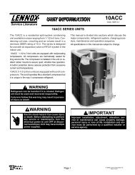
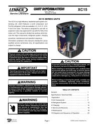
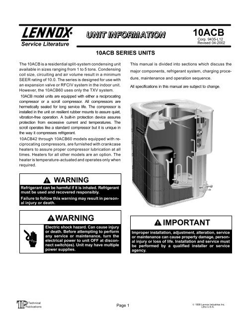
Service Literature<strong>10ACB</strong> SERIES UNITS<strong>10ACB</strong>Corp. 9435−L12Revised 04−2002The <strong>10ACB</strong> is a residential splitsystem condensing unitavailable in sizes ranging from 1 to 5 tons. Condensingcoil size, circuiting <strong>and</strong> air volume result in a minimumSEER rating of 10.0. The series is designed for use withan expansion valve or RFCIV system in the indoor unit.However, the <strong>10ACB</strong>60 uses only the TXV system.<strong>10ACB</strong> model units are equipped with either a reciprocatingcompressor or a scroll compressor. All compressors arehermetically sealed for long service life. The compressor isinstalled in the unit on resilient rubber mounts to assure quiet,vibrationfree operation. A builtin protection device assuresprotection from excessive current <strong>and</strong> temperatures. Thescroll operates like a st<strong>and</strong>ard compressor but it is unique inthe way it compresses refrigerant.<strong>10ACB</strong>42 through <strong>10ACB</strong>60 models equipped with reciprocating compressors, are furnished with crankcaseheaters to assure proper compressor lubrication at alltimes. Heaters for all other models are an option. Theheater is temperatureactuated <strong>and</strong> operates only whenrequired.This manual is divided into sections which discuss themajor components, refrigerant system, charging procedure, maintenance <strong>and</strong> operation sequence.All specifications in this manual are subject to change.WARNINGRefrigerant can be harmful if it is inhaled. Refrigerantmust be used <strong>and</strong> recovered responsibly.Failure to follow this warning may result in personal injury or death.WARNINGElectric shock hazard. Can cause injuryor death. Before attempting to performany service or maintenance, turn theelectrical power to unit OFF at disconnect switch(es). Unit may have multiplepower supplies.IMPORTANTImproper installation, adjustment, alteration, serviceor maintenance can cause property damage, personal injury or loss of life. Installation <strong>and</strong> service mustbe performed by a qualified installer or serviceagency.Page 1© 1999 Lennox Industries Inc.Litho U.S.A.
ELECTRICAL DATARECIPROCATING COMPRESSORSModel No.<strong>10ACB</strong>12−1 thru −10<strong>10ACB</strong>18−1 thru −10<strong>10ACB</strong>24−1 thru −10<strong>10ACB</strong>30−1 thru −10<strong>10ACB</strong>36−1 thru −11<strong>10ACB</strong>42−1 thru −10<strong>10ACB</strong>48−1 thru −9<strong>10ACB</strong>60−1 thru −9Line voltage data 60 hz − 1phase208/230vRated load amps 4.9 7.9 10.1 11.3 16.2 17.5 23.4 26.9Compressor Power factor .97 .96 .92 .90 .98 .98 .98Locked rotor amps 26.3 48.3 60 69.4 96 92.0 110.0 123.0Condenser Full load amps 1.1 1.9CoilFan Motor Locked rotor amps 1.9 4.1Rec. maximum fuse or circuit breakersize (amps)15 20 25 35 40 50 60*Minimum circuit ampacity 7.3 11.0 13.8 15.9 21.4 23.0 31.2 35.5*Refer to National or Canadian Electrical Code manual to determine wire, fuse <strong>and</strong> disconnect size requirements.NOTE Extremes of operating range are plus 10% <strong>and</strong> minus 5% of line voltage.ELECTRICAL DATASCROLL COMPRESSORSModel No. <strong>10ACB</strong>42−11 <strong>10ACB</strong>48−10 <strong>10ACB</strong>60−10Line voltage data 60 hz − 1 phase 208/230vRated load amps 17.9 21.8 25Compressor Power factor .84 .80 .90Locked rotor amps 103 131 170Condenser CoilFan MotorFull load amps 1.1 1.9Locked rotor amps 1.9 4.1Rec. maximum fuse or circuit breaker size (amps) 40 50 60*Minimum circuit ampacity 23.0 31.2 35.5*Refer to National or Canadian Electrical Code manual to determine wire, fuse <strong>and</strong> disconnect size requirements.NOTE Extremes of operating range are plus 10% <strong>and</strong> minus 5% of line voltage.Page 2
SPECIFICATIONSModel No. <strong>10ACB</strong>12 <strong>10ACB</strong>18 <strong>10ACB</strong>24 <strong>10ACB</strong>30 <strong>10ACB</strong>36CondenserCoilOuter coil 7.56 (0.70) 11.41 (1.06) 15.11 (1.40)Netfacearea−sq area sq. ft. (m 2 )Inner coil− − − −Tube diameter − in. (mm) & no. of rows 5/16 (7.9) 1Fins per inch (m) 18 (709) 22 (866)Diameter in. (mm) & no. of blades 18 (457) 3 18 (457) 4Motor hp (W) 1/6 (124)CondenserFanCfm (L/s) 2400 (1135) 2520 (1190)Rpm 1105 1100Watts 170 200*Refrigerant charge furnished (HCFC−22)2 lbs. 12 oz.(1.25 kg)3 lbs. 10 oz.(1.64 kg)4 lbs. 0 oz.(1.81 kg)4 lbs. 0 oz.(1.81 kg)5 lbs. 0 oz.(2.26 kg)Liquid line in. (mm) o.d. connection (sweat) 3/8 (9.5) 3/8 (9.5)Suction line in. (mm) o.d. connection (sweat) 5/8 (15.9) 3/4 (19.1)Shipping weight lbs. (kg) 1 package 146 (66) 148 (67) 150 (71) 165 (75)OPTIONAL ACCESSORIES − Must Be Ordered ExtraLow Ambient Kit − for use with expansion valve systems onlyLB−57113BC (24H77)Crankcase Heater 68887Timed−Off ControlLB−61378A (47J35)Hail Guards 17L71 17L73Unit St<strong>and</strong> Off KitMounting BaseCompressor Monitor (Optional for Canada Only)94J45MB2−S (69J06)t6−1469 (45F08)*Refrigerant charge sufficient for 20 ft. (6.0 m) length of refrigerant lines.3/8 x 5/16 in. (9.5 x 7.9 mm) adaptor furnished for liquid line connection.Page 3
SPECIFICATIONS Cont.Model No. <strong>10ACB</strong>42 <strong>10ACB</strong>48 <strong>10ACB</strong>60Outer coil 15.11 (1.40)Net face area − sq. ft. (m 2 )CondenserInner coil 5.40 (0.50) 14.40 (1.34)Coil Tube diameter in. (mm) & no. of rows 5/16 (7.9) 1.37 5/16 (7.9) 2Fins per inch (m) 22 (866)Diameter in. (mm) & no. of blades 18 (457) 4Motor hp (W) 1/6 (124) 1/3 (249)CondenserFanCfm (L/s) 2500 (1180) 2950 (1390) 2930 (1385)Rpm 1100Watts 200 310*Refrigerant charge furnished (HCFC−22) 5 lbs. 7 oz. (2.47 kg) 6 lbs. 6 oz. (2.89 kg) 8 lbs. 8 oz. (3.86 kg)Liquid line in. (mm) o.d. connection (sweat) 3/8 (9.5)Suction line in. (mm) o.d. connection (sweat) 7/8 (22.2) 1−1/8 (28.6)Shipping weight lbs. (kg) 1 package 191 (87) 196 (89) 212 (96)OPTIONAL ACCESSORIES − Must Be Ordered ExtraLow Ambient Kit − for use with expansion valve systems onlyLB−57113BC (24H77)Crankcase Heater90P12Timed−Off ControlLB−61378A (47J35)Hail Guards17L73Unit St<strong>and</strong> Off Kit94J45Mounting BaseMB2−S (69J06)Compressor Monitor (Optional for Canada Only)T6−1469 (45F08)*Refrigerant charge sufficient for 20 ft. (6.0 m) length of refrigerant lines.I − UNIT INFORMATIONDANGERMake sure all power is disconnected beforebeginning electrical service procedures.<strong>10ACB</strong> UNIT COMPONENTSOUTDOORFAN/MOTORCONTROLBOX<strong>10ACB</strong> condensing units are available in 1, 1 1/2, 2, 2 1/2, 3,3 1/2, 4 <strong>and</strong> 5 ton capacities.All major components (indoor blower <strong>and</strong> coil) must bematched according to Lennox recommendations for the compressor to be covered under warranty. Refer to the Engineering H<strong>and</strong>book for approved system matchups. A misappliedsystem will cause erratic operation <strong>and</strong> can result in early compressor failure.II − UNIT COMPONENTSUnit components are illustrated in figure 1.COMPRESSORSUCTION LINEFIGURE 1DISCHARGELINESUCTION LINESERVICE VALVELIQUID LINESERVICE VALVEPage 4
STARTCAPACITOR (C7)(3.5, 4 & 5 ton)COMPRESSORCONTACTOR(K1)GROUNDINGLUG<strong>10ACB</strong> UNIT CONTROL BOXRECIPROCATING COMPRESSORDUAL CAPACITOR(C12)POTENTIALRELAY (K31)(3.5, 4 & 5 ton)<strong>10ACB</strong> units are not equipped with a 24V transformer. All24 VAC controls are powered by the indoor unit. Refer towiring diagram.DANGERShock HazardSome <strong>10ACB</strong> units use singlepolecontactors. One leg of compressor, capacitor <strong>and</strong> condenser fanare connected to line voltage at alltimes. Potential exists for electrical shock resulting in injury ordeath. Remove all power at disconnect before servicing.Can cause personal injury or death.2 − Dual Capacitor C12COMPRESSORCONTACTOR(K1)GROUNDINGLUGFIGURE 2<strong>10ACB</strong> UNIT CONTROL BOX−042, −048 <strong>and</strong> −060 with ScrollDUAL CAPACITOR(C12)FIGURE 3A − Control Box (Figures 2 & 3)Electrical openings are provided under the control box cover. Field thermostat wiring is made to colorcoded pigtailconnections.1 − Compressor Contactor K1The compressor is energized by a contactor located in thecontrol box. See figure 2. Single−pole <strong>and</strong> twopole contactors are used in <strong>10ACB</strong> units. See wiring diagrams forspecific units. K1 is energized by the indoor thermostatterminal Y1 (24V) when thermostat dem<strong>and</strong> is present.The compressor <strong>and</strong> fan in <strong>10ACB</strong> series units use permanent split capacitor motors. The capacitor is locatedinside the unit control box (see figures 2 <strong>and</strong> 3). A singledual" capacitor (C12) is used for both the fan motor <strong>and</strong>the compressor (see unit wiring diagram). The fan side<strong>and</strong> the compressor side of the capacitor have differentMFD ratings. For ratings see side of capacitor.3 − Start Capacitor C7All <strong>10ACB</strong> 3 1/2, 4 <strong>and</strong> 5 ton series units equipped with areciprocating compressor, use a start capacitor (C7) wiredin parallel with the compressor side of the dual capacitor.The capacitor is located inside the unit control box (seefigure 2). C7 is switched off by potential relay (K31) whenthe compressor nears full speed.The start capacitor israted at 330 VAC <strong>and</strong> has an MFD rating of 176−216.4 − Potential (Start) Relay K31All <strong>10ACB</strong> 3 1/2, 4 <strong>and</strong> 5 ton series units equipped with a reciprocating compressor use a potential relay which controlsthe operation of the starting circuit. The potential relay islocated inside the unit control box (see figure 2). Therelay is normally closed when contactor K1 is deenergized. When K1 energizes, the compressor immediatelybegins startup. K31 remains closed during compressorstartup <strong>and</strong> the start capacitor C7 remains in the circuit.When the compressor reaches 75% of its speed, K31 is energized. When K31 energizes, the contacts open <strong>and</strong> the startcapacitor C7 is taken out of the circuit.Page 5
B − CompressorAll <strong>10ACB</strong> units built prior to May of 1998 utilize a conventional reciprocating compressor. <strong>10ACB</strong>−042, −048<strong>and</strong> −060 units built after May of 1998 will be equippedwith a scroll compressor. For compressor specifications see ELECTRICAL DATA" section in this manual orthe compressor nameplate.DISCHARGEPRESSURECROSS−SECTION OF SCROLLSDISCHARGESTATIONARY SCROLLSUCTIONSCROLL COMPRESSORDISCHARGESUCTIONFIGURE 41 − Scroll CompressorThe scroll compressor design is simple, efficient <strong>and</strong> requires few moving parts. A cutaway diagram of the scrollcompressor is shown in figure 4.The scrolls are located inthe top of the compressor can <strong>and</strong> the motor is located justbelow. The oil level is immediately below the motor.The scroll is a simple compression concept centeredaround the unique spiral shape of the scroll <strong>and</strong> its inherentproperties. Figure 5 shows the basic scroll form. Two identical scrolls are mated together forming concentric spiralshapes (figure 6 ). One scroll remains stationary, while theother is allowed to orbit" (figure 7). Note that the orbitingscroll does not rotate or turn but merely orbits" the stationary scroll.SCROLL FORMORBITING SCROLLTIPS SEALED BYDISCHARGE PRESSUREFIGURE 6The counterclockwise orbiting scroll draws gas into the outer crescent shaped gas pocket created by the two scrolls(figure 7 − 1). The centrifugal action of the orbiting scrollseals off the flanks of the scrolls (figure 7 − 2). As the orbitingmotion continues, the gas is forced toward the center of thescroll <strong>and</strong> the gas pocket becomes compressed (figure 7 −3). When the compressed gas reaches the center, it is discharged vertically into a chamber <strong>and</strong> discharge port in thetop of the compressor (figure 6). The discharge pressureforcing down on the top scroll helps seal off the upper <strong>and</strong>lower edges (tips) of the scrolls (figure 6 ). During a singleorbit, several pockets of gas are compressed simultaneously providing smooth continuous compression.The scroll compressor is tolerant to the effects of liquid return. If liquid enters the scrolls, the orbiting scroll is allowedto separate from the stationary scroll. The liquid is workedtoward the center of the scroll <strong>and</strong> is discharged. If thecompressor is replaced, conventional Lennox cleanuppractices must be used.Due to its efficiency, the scroll compressor is capable ofdrawing a much deeper vacuum than reciprocating compressors. Deep vacuum operation can cause internal fusite arcing resulting in damaged internal parts <strong>and</strong> will result in compressor failure. Never use a scroll compressorfor evacuating or pumping−down" the system. This type ofdamage can be detected <strong>and</strong> will result in denial of warranty claims.NOTE − During operation, the head of a scroll compressormay be hot since it is in constant contact with dischargegas.FIGURE 5Page 6
SUCTIONPOCKET1SUCTIONSTATIONARY SCROLLSUCTIONHOW A SCROLL WORKSMOVEMENT OF ORBITORBITINGSCROLLSUCTION2FLANKSSEALED BYCENTRIFUGALFORCESUCTIONINTERMEDIATEPRESSUREGASCRESCENTSHAPED GASPOCKET3 4HIGHPRESSUREGAS2 − Crankcase HeaterA crankcase heater is used on all <strong>10ACB</strong>42 through<strong>10ACB</strong>60 models equipped with a reciprocating compressor. For all other models the crankcase heater is anoption <strong>and</strong> must be ordered seperate. See SPECIFICATIONS" section in this manual for part number. Thewellmounted insertiontype heater is selfregulating.All heaters used on reciprocating compressors arerated at 27 watts. The heater is temperatureactuated<strong>and</strong> operates only when required.C − Condenser Fan MotorAll units use single−phase PSC fan motors which require a runcapacitor. In all units, the condenser fan is controlled by thecompressor contactor.ELECTRICAL DATA tables in this manual show specifications for condenser fans used in <strong>10ACB</strong>s.Access to the condenser fan motor on all units is gainedby removing the seven screws securing the fan assembly. See figure 8. The condenser fan motor is removedfrom the fan guard by removing the four nuts found onthe top panel. See figure 9 if condenser fan motor replacement is necessary.FIGURE 7Remove (7) screwsRemove (4) nutsFANDISCHARGEPOCKETCONDENSER FAN MOTORAND COMPRESSOR ACCESSMOTORRACEWAYREMOVE (7) SCREWSSECURING FAN GUARD.REMOVE FAN GUARD/FANASSEMBLY.FIGURE 8ALIGN FAN HUB FLUSH WITH END OF SHAFTFIGURE 9FAN GUARDWIRINGPage 7
III − REFRIGERANT SYSTEMA − PlumbingField refrigerant piping consists of liquid <strong>and</strong> suction linesfrom the condensing unit (sweat connections) to the indoorevaporator coil (flare or sweat connections). Use LennoxL10 (flare) or L15 (sweat, non−flare) series line sets asshown in table 1 or use field−fabricated refrigerant lines.Separate discharge <strong>and</strong> suction service ports are provided outside the unit for connection of gauge manifoldduring charging procedure.TABLE 1CondensingUnitModel No.Line SetLength of Liquid Line Suction LineModel No.Lines Outside Dia. Outside Dia.(L10 or L15) ft. m in. mm in. mmL10/152120 20 6<strong>10ACB</strong>12 L10/152125 25 8<strong>10ACB</strong>185/16 79 7.9 5/8 15.9L10/152135 35 11<strong>10ACB</strong>24L10/152150 50 15L10/154120 20 6<strong>10ACB</strong>30 L10/154130 30 9<strong>10ACB</strong>36 L10/154140 40 123/8 95 9.5 3/4 19L10/154150 50 15L10/156530 30 9<strong>10ACB</strong>42L10/156540 40 12 <strong>10ACB</strong>48L10/156550 50 153/8 9.5 7/8 22.2<strong>10ACB</strong>60 *Field fabricate 3/8 9.5 11/8 28.5*Field fabricate. See Corp. 9351−L9 Refrigerant Piping NabualB − Service ValvesThe liquid <strong>and</strong> suction line service valves (figures 10 <strong>and</strong> 11)<strong>and</strong> gauge ports are accessible from outside the unit.The valve is equipped with a service port. The service portsare used for leak testing, evacuating, charging <strong>and</strong> checkingcharge. A schrader valve is factory installed. A service port capis supplied to protect the schrader valve from contamination<strong>and</strong> serve as the primary leak seal.NOTEAlways keep valve stem caps clean.To Access Schrader Port:1 − Remove service port cap with an adjustable wrench.2 − Connect gauge to the service port.3 − When testing is completed, replace service port cap.Tighten finger tight, then an additional 1/6 turn.To Open Liquid or Suction Line Service Valve:1 − Remove stem cap with an adjustable wrench.2 − Using service wrench <strong>and</strong> 5/16" hex head extensionback the stem out counterclockwise until the valve stemjust touches the retaining ring.3 − Replace stem cap tighten firmly. Tighten finger tight, thentighten an additional 1/6 turn.DANGERDo not attempt to backseat this valve. Attempts tobackseat this valve will cause snap ring to explodefrom valve body under pressure of refrigerant.Personal injury <strong>and</strong> unit damage will result.To Close Liquid or Suction Line Service Valve:1 − Remove stem cap with an adjustable wrench.2 − Using service wrench <strong>and</strong> 5/16" hex head extension, turnstem clockwise to seat the valve. Tighten firmly.3 − Replace stem cap. Tighten finger tight, then tighten anadditional 1/6 turn.LIQUID LINE SERVICE VALVE (VALVE OPEN)SERVICEPORTOUTLET (TOCOMPRESSOR)SERVICEPORTCAPINSERT HEXWRENCH HERESCHRADERVALVESERVICEPORTSERVICEPORT CAPSCHRADER VALVE OPENTO LINE SET WHEN VALVEIS CLOSED (FRONTSEATED)FIGURE 10STEM CAPINLET (TOINDOOR COIL)LIQUID LINE SERVICE VALVE (VALVE CLOSED)RETAINING RING STEM CAPOUTLET (TOCOMPRESSOR)INSERT HEXWRENCH HEREINLET(TO INDOOR COIL)(VALVE FRONTSEATED)Page 8
SUCTION LINE SERVICE VALVE (VALVE OPEN)INSERT HEXWRENCH HEREINLET (TOINDOOR COIL)STEM CAPSUCTION LINE (BALL TYPE) SERVICE VALVE(VALVE OPEN)USE ADJUSTABLE WRENCHROTATE STEM CLOCKWISE 90 TO CLOSEROTATE STEM COUNTERCLOCKWISE 90 TO OPENINLET(FROM INDOOR COIL)STEM CAPSCHRADERVALVESERVICE PORTCAPSERVICEPORTSERVICE PORTCAPSERVICE PORTRETAINING RINGSCHRADER VALVE OPENTO LINE SET WHEN VALVE ISCLOSED (FRONT SEATED)FIGURE 11OUTLET (TOCOMPRESSOR)SUCTION LINE SERVICE VALVE (VALVE CLOSED)INLET (TOINDOOR COIL)STEM CAPINSERT HEXWRENCH HERE(VALVE FRONTSEATED)OUTLET (TOCOMPRESSOR)Suction Line (Ball Type) Service Valve(5 Ton Only)A balltype full service valve is used on <strong>10ACB</strong> 5 tonunits. These suction line service valves function thesame way, differences are in construction. Valves arenot rebuildable. If a valve has failed it must be replaced. A ballvalve is illustrated in figure 12.The ball valve is equipped with a service port. A schrader valveis factory installed. A service port cap is supplied to protect theschrader valve from contamination <strong>and</strong> assure a leak freeseal.SERVICEPORTCAPIV − CHARGINGSTEMSERVICE PORTSCHRADER COREFIGURE 12BALL(SHOWN OPEN)OUTLET(TOCOMPRESSOR)The unit is factory−charged with the amount of R−22 refrigerant indicated on the unit rating plate. This charge isbased on a matching indoor coil <strong>and</strong> outdoor coil with a 20foot (6.1 m) line set. For varying lengths of line set, refer totable 2 for refrigerant charge adjustment. A blank space is provided on the unit rating plate to list actual field charge.TABLE 2LIQUID LINE Ounce per 5 foot (ml per mm) adjustSET DIAMETERfrom 20 foot (6.1 m) line set*1/4 in. (6 mm) 1 ounce per 5 feet (30 ml per 1524 mm)5/16 in. (8mm) 2 ounce per 5 feet (60 ml per 1524 mm)3/8 in. (10 mm) 3 ounce per 5 feet (90 ml per 1524 mm)*If line set is greater than 20 ft. (6.1 m) add this amount. If line setis less than 20 feet (6.1 m) subtract this amountUnits are designed for line sets up to 50 ft (15.2 m). Consult Lennox Refrigerant Piping Manual for line sets over50 ft (15.2 m).IMPORTANTIf line length is greater than 20 feet (6.1 m) add thisamount. If line length is less than 20 feet (6.1 m),subtract this amount. See table 2.Page 9
A − Pumping Down SystemCAUTIONDeep vacuum operation (operating compressor at 0psig or lower) can cause internal fusite arcingresulting in a damaged or failed compressor. Thistype of damage will result in denial of warranty claim.The system may be pumped down when leak checking theline set <strong>and</strong> indoor coil or making repairs to the line set orindoor coil.1− Attach gauge manifold.2− Front seat (close) liquid line valve.3− Start outdoor unit.4− Monitor suction gauge. Stop unit when 0 psig is reached.5− Front seat (close) suction line valve.B − Leak Testing (To Be DoneBefore Evacuating)1− Attach gauge manifold <strong>and</strong> connect a drum of dry nitrogen to center port of gauge manifold.2− Open high pressure valve on gauge manifold <strong>and</strong>pressurize line set <strong>and</strong> indoor coil to 150 psig (1034kPa).3− Check lines <strong>and</strong> connections for leaks.NOTEIf electronic leak or Halide detector is used, add asmall amount of R−22 (3 to 5 psig [20kPa to 34kPa]) thenpressurize with nitrogen to 150 psig.4− Release nitrogen pressure from the system, correct anyleaks <strong>and</strong> recheck.CAUTIONWhen using dry nitrogen, a pressure reducing regulator must be used to prevent excessive pressure in gauge manifold, connecting hoses, <strong>and</strong>within the system. Regulator setting must not exceed 150 psig (1034 kpa). Failure to use a regulatorcan cause equipment failure resulting in injury.C − Evacuating the System1− Attach gauge manifold. Connect vacuum pump (with vacuum gauge) to center port of gauge manifold. With bothmanifold service valves open, start pump <strong>and</strong> evacuateindoor coil <strong>and</strong> refrigerant lines.IMPORTANTA temperature vacuum gauge, mercury vacuum(U−tube), or thermocouple gauge should be used.The usual Bourdon tube gauges are not accurateenough in the vacuum range.IMPORTANTThe compressor should never be used to evacuate a refrigeration or air conditioning system.2− Evacuate the system to 29 inches (737mm) vacuum.During the early stages of evacuation, it is desirable tostop the vacuum pump at least once to determine if thereis a rapid loss of vacuum. A rapid loss of vacuum wouldindicate a leak in the system <strong>and</strong> a repeat of the leak testing section would be necessary.3− After system has been evacuated to 29 inches(737mm), close gauge manifold valves to center port,stop vacuum pump <strong>and</strong> disconnect from gauge manifold. Attach an upright nitrogen drum to center port ofgauge manifold <strong>and</strong> open drum valve slightly to purgeline at manifold. Break vacuum in system with nitrogen pressure by opening manifold high pressurevalve. Close manifold high pressure valve to centerport.4− Close nitrogen drum valve <strong>and</strong> disconnect fromgauge manifold center port. Release nitrogen pressure from system.5− Connect vacuum pump to gauge manifold centerport. Evacuate system through manifold servicevalves until vacuum in system does not rise above.5mm of mercury absolute pressure or 500 micronswithin a 20−minute period after stopping vacuum pump.6− After evacuation is complete, close manifold center port,<strong>and</strong> connect refrigerant drum. Pressurize systemslightly with refrigerant to break vacuum.D − ChargingIf the system is completely void of refrigerant, the recommended <strong>and</strong> most accurate method of charging is to weighthe refrigerant into the unit according to the total amountshown on the unit nameplate. Also refer to the SPECIFICATIONS tables at the front of this manual.If weighing facilities are not available or if unit is just low oncharge, the following procedure applies.1 − Expansion Valve SystemsThe following procedures are intended as a general guide foruse with expansion valve systems only. For best results, indoor temperature should be between 70°F <strong>and</strong> 80°F (21.1°C<strong>and</strong> 26.7°C). Outdoor temperature should be 60°F (15.6°C) orabove. Slight variations in charging temperature <strong>and</strong> pressureshould be expected. Large variations may indicate need forfurther servicing.IMPORTANTThe following procedure requires accurate readings of ambient (outdoor) temperature, liquid temperature <strong>and</strong> liquid pressure for proper charging.Use a thermometer with accuracy of +2 °F (+ 1.1°C)<strong>and</strong> a pressure gauge with accuracy of +5 PSIG (+34.5 kPa).Page 10
APPROACH METHOD (TXV SYSTEMS)(Ambient Temperature of 60F [16C] or Above)1 − Connect gauge manifold. Connect an upright R−22drum to center port of gauge manifold.2 − Record outdoor air (ambient) temperature.3 − Operate indoor <strong>and</strong> outdoor units in cooling mode.Allow outdoor unit to run until system pressures stabilize.4 − Make sure thermometer well is filled with mineral oilbefore checking liquid line temperature.5 − Place thermometer in well <strong>and</strong> read liquid line temperature. Liquid line temperature should be warmerthan the outdoor air temperature. Tables 3 <strong>and</strong> 4show how many degrees warmer the liquid line temperature should be.Add refrigerant to lower the liquid line temperature.Recover refrigerant to raise the liquid line temperature.Add refrigerant slowly as the unit approaches thecorrect temperature. This will allow refrigerantto stabilize allowing the correct temperature tobe read.75°F (23.9°C) (RFCIV)85°F (29.4°C) (RFCIV)95°F (35.0°C) (RFCIV)105°F (40.6°C) (RFCIV)65°F (18.3°C) (TXV)75°F (23.92°C) (TXV)85°F (31.2°C) (TXV)95°F (31.2°C) (TXV)105°F (31.2°C) (TXV)270159183209238269847375778082280164189217247279827173757880292173199228258292807173757779MODELNO.TABLE 3−1 through −8 ModelsAPPROACH TEMPERATURELIQUID LINE − OUTDOOR AMBIENT F (C)<strong>10ACB</strong>18 4 (2.2)<strong>10ACB</strong>24 5 (2.8)<strong>10ACB</strong>30 10 (5.6)<strong>10ACB</strong>36 12 (6.7)<strong>10ACB</strong>42 12 (6.7)<strong>10ACB</strong>48 13 (7.2)<strong>10ACB</strong>60 13 (7.2)Note − For best results, the same electronic thermometer should be usedto check both outdoor ambient <strong>and</strong> liquid temperatures.TABLE 4−9 <strong>and</strong> Higher ModelsMODELNO.APPROACH TEMPERATURELIQUID LINE − OUTDOOR AMBIENT F (C)<strong>10ACB</strong>12 7 (3.9)<strong>10ACB</strong>18 5 (2.8)<strong>10ACB</strong>24 9 (5)<strong>10ACB</strong>30 10 (5.6)<strong>10ACB</strong>36 12 (6.7)<strong>10ACB</strong>42 14 (8)<strong>10ACB</strong>48 13 (7.2)<strong>10ACB</strong>60 12 (6.7)Note − For best results, the same electronic thermometer should be usedto check both outdoor ambient <strong>and</strong> liquid temperatures.6 − When unit is properly charged, liquid line pressuresshould approximate those in table 5 or table 6.TABLE 5−1 through −8 ModelsNORMAL OPERATING PRESSURES*<strong>10ACB</strong>18 <strong>10ACB</strong>24 <strong>10ACB</strong>30 <strong>10ACB</strong>36 <strong>10ACB</strong>42 <strong>10ACB</strong>48 <strong>10ACB</strong>60OUTDOOR COILENTERING AIRLIQ. SUC. LIQ. SUC. LIQ. SUC. LIQ. SUC. LIQ. SUC. LIQ. SUC. LIQ. SUC.TEMPERATURE + 10 + 10 + 10 + 10 + 10 + 10 + 10 + 10 + 10 + 10 + 10 + 10 + 10 + 10PSIG PSIG PSIG PSIG PSIG PSIG PSIG PSIG PSIG PSIG PSIG PSIG PSIG PSIG65°F (18.3°C) (RFCIV) 155 65 160 65 168 63 176 62 174 64 181 65 −−− −−−181 70 188 70 197 68 203 66 205 69 208 70 −−− −−−208 75 216 74 227 73 233 70 236 73 239 75 −−− −−−238 80 247 78 258 77 266 74 271 77 271 79 −−− −−−−−− −−−*These are typical pressures only. Indoor evaporator match up, indoor air quality <strong>and</strong> evaporator load will cause the pressures to vary.2991792052352662997768707274773051802082382713058071737577793061872122412713058273757779801742032352693067072747678Page 11
MODEOUT. COILENTERINGAIR TEMP.°F (°C)TABLE 6−9 <strong>and</strong> Higher ModelsNORMAL OPERATING PRESSURES IN PSIG (LIQUID AND SUCTION +/− 10 PSIG)*<strong>10ACB</strong>12 <strong>10ACB</strong>18 <strong>10ACB</strong>24 <strong>10ACB</strong>30 <strong>10ACB</strong>36 <strong>10ACB</strong>42 <strong>10ACB</strong>48 <strong>10ACB</strong>60 <strong>10ACB</strong>62LIQ. SUC. LIQ. SUC. LIQ. SUC. LIQ. SUC. LIQ. SUC. LIQ. SUC. LIQ. SUC. LIQ. SUC. LIQ. SUC.65 (18.3) 145 71 155 65 160 65 168 63 176 62 162 68 157 69 153 66 159 6475 (23.9) 167 77 181 70 188 70 197 68 203 66 185 72 182 72 180 71 188 68RFCIV 85 (29.4) 192 81 208 75 216 74 227 73 233 70 210 73 204 73 210 74 219 7295 (35.0) 221 84 238 80 247 78 258 77 266 74 252 76 244 76 245 77 253 75105 (40.6) 253 87 270 84 280 82 292 80 299 77 287 79 278 79 279 79 287 7665 (18.3) 140 79 159 73 164 71 173 71 179 68 157 71 158 70 142 73 151 6975 (23.9) 161 80 183 75 189 73 199 73 205 70 187 73 182 72 168 75 179 71TXV 85 (29.4) 189 81 209 77 217 75 228 75 235 72 217 74 205 73 202 76 211 7395 (35.0) 220 83 238 80 247 78 258 77 266 74 255 76 246 76 245 77 249 74105 (40.6) 254 84 269 82 279 80 292 79 299 77 289 77 280 79 280 78 286 75*These are typical pressures only. Indoor evaporator match up, indoor air quality <strong>and</strong> evaporator load will cause the pressures to vary.IMPORTANTUse table 5 or 6 as a general guide for performingmaintenance checks. Tables 5 <strong>and</strong> 6 are not a procedure for charging the system. Minor variations inthese pressures may be expected due to differences in installations. Significant deviations couldmean that the system is not properly charged orthat a problem exists with some component in thesystem. Used prudently, tables 5 <strong>and</strong> 6 could serveas a useful service guide.2 − RFCIV SystemsThe following procedures are intended as a general guide foruse with RFCIV systems only. For best results, indoor temperature should be between 70°F <strong>and</strong> 80°F (21.1°C <strong>and</strong> 26.7°C).Outdoor temperature should be 60°F (15.6°C) or above. Slightvariations in charging temperature <strong>and</strong> pressure should be expected. Large variations may indicate a need for further servicing.1 − Operate indoor <strong>and</strong> outdoor units. Allow outdoor unitto run until system pressures stabilize.2 − Make sure thermometer well is filled with mineral oilbefore checking liquid line temperature.3 − Read liquid line pressure <strong>and</strong> convert to condensing temperature using temperature/ pressure conversion chart.Condensing temperature (read from gauges) shouldbe warmer than liquid line temperature.4 − Place thermometer in well <strong>and</strong> read liquid line temperature. Tables 7 <strong>and</strong> 8 shows how much warmer thecondensing temperature should be.5 − Subtract liquid line temperature from condensing temperature to determine subcooling. Comparewith table 7 or 8.Add refrigerant to lower liquid line temperature.Recover refrigerant to raise liquid line temp.6 − When unit is properly charged liquid line pressures should approximate table 5 or 6.Page 12
TABLE 7−1 through −8 ModelsOutdoorTemperatureLiquid Subcooling (+ 1F or 0.5 C)F(C)<strong>10ACB</strong>18 <strong>10ACB</strong>24 <strong>10ACB</strong>30 <strong>10ACB</strong>36 <strong>10ACB</strong>42 <strong>10ACB</strong>4860 (16)65 (18)70 (21)75 (24)80 (27)85 (29)90 (32)95 (35)100 (38)105 (41)110 (43)115 (46)17 (9.5)16 (8.9)15 (8.3)14 (8)13 (7.8)12 (6.7)11 (6.1)9 (5)8 (4.4)7 (3.9)6 (3.3)5 (2.8)18 (10)16 (8.9)14 (8)12 (6.7)11 (6.1)10 (5.6)9 (5)8 (4.4)7 (3.9)6 (3.3)6 (3.3)5 (2.8)18 (10)17 (9.5)16 (8.9)15 (8.3)14 (8)13 (7.8)12 (6.7)11 (6.1)10 (5.6)9 (5)7 (3.9)5 (2.8)14 (8)13 (7.8)12 (6.7)10 (5.6)9 (5)8 (4.4)7 (3.9)6 (3.3)5 (2.8)4 (2.2)3 (1.7)2 (1.1)16 (8.9)15 (8.3)14 (8)13 (7.8)12 (6.7)11 (6.1)10 (5.6)9 (5)8 (4.4)6 (3.3)5 (2.8)3 (1.7)15 (8.3)14 (8)13 (7.8)11 (6.1)10 (5.6)8 (4.4)7 (3.9)7 (3.9)6 (3.3)4 (2.2)3 (1.7)2 (1.1)TABLE 8−9 <strong>and</strong> Higher ModelsOUTDOOR LIQUID SUBCOOLING [+ 1F (.6C)]TEMP.F (C) 012 018 024 030 036 042 048 06060(16)65(18)70(21)75(24)80(27)85(29)90(32)95(35)100(38)105(41)110(43)115(45)14(7.8)13(7.2)12(6.7)10(5.6)9(5)8(4.5)7(3.9)6(3.3)4(2.2)2(1.1)2(1.1)1(0.6)17(9.5)16(8.9)15(8.3)14(7.8)13(7.2)12(6.7)11(6.1)9(5)8(4.5)7(3.9)6(3.3)5(2.8)18(10)16(8.9)14(7.8)12(6.7)11(6.1)10(5.6)9(5)8(4.5)7(3.9)6(3.3)6(3.3)5(2.8)18(10)17(9.5)16(8.9)15(8.3)14(8)13(7.8)12(6.7)11(6.1)10(5.6)9(5)7(3.9)5(2.8)14(8)13(7.8)12(6.7)10(5.6)9(5)8(4.4)7(3.9)6(3.3)5(2.8)4(2.2)3(1.7)2(1.1)14(8)13(7.8)13(7.8)12(6.7)11(6.1)10(5.6)10(5.6)9(5)9(5)9(5)8(4.5)7(3.9)12(6.7)11(6.1)10(5.6)9(5)9(5)9(5)8(4.5)8(4.5)8(4.5)7(3.9)7(3.9)6(3.3)14(8)14(8)13(7.8)13(7.8)12(6.7)12(6.7)12(6.7)12(6.7)11(6.1)10(5.6)9(5)8(4.5)Note − For best results, the same electronic thermometer should be usedto check both outdoor ambient <strong>and</strong> liquid temperatures.E − Oil ChargeRefer to compressor nameplate.V − MAINTENANCEAt the beginning of each heating or cooling season, thesystem should be cleaned as follows:A − Outdoor Unit1 − Clean <strong>and</strong> inspect condenser coil. (Coil may beflushed with a water hose).2 − Visually inspect all connecting lines, joints <strong>and</strong>coils for evidence of oil leaks.B − Indoor Coil1 − Clean coil if necessary.2 − Check connecting lines <strong>and</strong> coil for evidence of oilleaks.3 − Check condensate line <strong>and</strong> clean if necessary.C − Indoor Unit1 − Clean or change filters.2 − Bearings are prelubricated <strong>and</strong> need no further oiling.3 − Check all wiring for loose connections.4 − Check for correct voltage at unit.5 − Check amp−draw on blower motor.Unit nameplate_________Actual_________.Page 13
VI − WIRING DIAGRAMS AND SEQUENCE OF OPERATION<strong>10ACB</strong> OPERATING SEQUENCERECIPROCATING COMPRESSOR15264734A−<strong>10ACB</strong> 11/2 − 3 TON OPERATING SEQUENCEThis is the sequence of operation for <strong>10ACB</strong> 11/2 through 3 ton units. The sequence is outlined by numbered steps whichcorrespond to circled numbers on the adjacent diagram.NOTE− The thermostat used may be electromechanical or electronic.NOTE− Transformer in indoor unit supplies power (24 VAC) to the thermostat <strong>and</strong> outdoor unit controls.COOLING:1 − Cooling dem<strong>and</strong> initiates at Y1 in the thermostat.2 − 24VAC energizes compressor contactor K1.3 − K11 N.O. closes, energizing compressor (B1) <strong>and</strong> outdoor fan motor (B4).4 − Compressor (B1) <strong>and</strong> outdoor fan motor (B4) begin immediate operation.END OF COOLING DEMAND:5 − Cooling dem<strong>and</strong> is satisfied. Terminal Y1 is deenergized.6 − Compressor contactor K1 is deenergized.7 − K11 opens <strong>and</strong> compressor (B1) <strong>and</strong> outdoor fan motor (B4) are deenergized <strong>and</strong> stop immediately.Page 14
<strong>10ACB</strong> OPERATING SEQUENCERECIPROCATING COMPRESSOR15264374A−<strong>10ACB</strong> 11/2 − 3 TON OPERATING SEQUENCEThis is the sequence of operation for <strong>10ACB</strong> 11/2 through 3 ton units. The sequence is outlined by numbered steps whichcorrespond to circled numbers on the adjacent diagram.NOTE− The thermostat used may be electromechanical or electronic.NOTE− Transformer in indoor unit supplies power (24 VAC) to the thermostat <strong>and</strong> outdoor unit controls.COOLING:1 − Cooling dem<strong>and</strong> initiates at Y1 in the thermostat.2 − 24VAC energizes compressor contactor K1.3 − K11 N.O. closes, energizing compressor (B1) <strong>and</strong> outdoor fan motor (B4).4 − Compressor (B1) <strong>and</strong> outdoor fan motor (B4) begin immediate operation.END OF COOLING DEMAND:5 − Cooling dem<strong>and</strong> is satisfied. Terminal Y1 is deenergized.6 − Compressor contactor K1 is deenergized.7 − K11 opens <strong>and</strong> compressor (B1) <strong>and</strong> outdoor fan motor (B4) are deenergized <strong>and</strong> stop immediately.Page 15
<strong>10ACB</strong> OPERATING SEQUENCERECIPROCATING COMPRESSOR16273854A−<strong>10ACB</strong> 31/2 − 5 TON OPERATING SEQUENCEThis is the sequence of operation for <strong>10ACB</strong> 31/2 through 5 ton units. The sequence is outlined by numbered steps whichcorrespond to circled numbers on the adjacent diagram.NOTE− The thermostat used may be electromechanical or electronic.NOTE− Transformer in indoor unit supplies power (24 VAC) to the thermostat <strong>and</strong> outdoor unit controls.COOLING:1 − Cooling dem<strong>and</strong> initiates at Y1 in the thermostat.2 − 24VAC from indoor unit energizes compressor contactor K1.3 − K11 N.O. closes, energizing terminal C" of compressor (B1) <strong>and</strong> outdoor fan motor (B4).4 − Outdoor fan motor (B4) begins immediate operation.5 − Compressor (B1) begins startup. Hard start contactor K31 remains closed during startup <strong>and</strong> start capacitor C7 remainsin the circuit. As the compressor gains speed, K31 is energized. When K31 is energized, the contacts open <strong>and</strong> startcapacitor C7 is taken out of the circuit.END OF COOLING DEMAND:6 − Cooling dem<strong>and</strong> is satisfied. Terminal Y1 is deenergized.7 − Compressor contactor K1 is deenergized.8 − K11 opens <strong>and</strong> compressor (B1) <strong>and</strong> outdoor fan motor (B4) are deenergized <strong>and</strong> stop immediately.Page 16
<strong>10ACB</strong> OPERATING SEQUENCESCROLL COMPRESSOR16275834A−<strong>10ACB</strong> 31/2 − 5 TON OPERATING SEQUENCEThis is the sequence of operation for <strong>10ACB</strong> 31/2 through 5 ton units. The sequence is outlined by numbered steps whichcorrespond to circled numbers on the adjacent diagram.NOTE− The thermostat used may be electromechanical or electronic.NOTE− Transformer in indoor unit supplies power (24 VAC) to the thermostat <strong>and</strong> outdoor unit controls.COOLING:1 − Cooling dem<strong>and</strong> initiates at Y1 in the thermostat.2 − 24VAC from indoor unit energizes compressor contactor K1.3 − K11 N.O. closes, energizing terminal C" of compressor (B1) <strong>and</strong> outdoor fan motor (B4).4 − Outdoor fan motor (B4) begins immediate operation.5 − Compressor (B1) begins startup.END OF COOLING DEMAND:6 − Cooling dem<strong>and</strong> is satisfied. Terminal Y1 is deenergized.7 − Compressor contactor K1 is deenergized.8 − K11 opens <strong>and</strong> compressor (B1) <strong>and</strong> outdoor fan motor (B4) are deenergized <strong>and</strong> stop immediately.Page 17
<strong>10ACB</strong> OPERATING SEQUENCESCROLL COMPRESSOR16275834A−<strong>10ACB</strong> 31/2 − 5 TON OPERATING SEQUENCEThis is the sequence of operation for <strong>10ACB</strong> 31/2 through 5 ton units. The sequence is outlined by numbered steps whichcorrespond to circled numbers on the adjacent diagram.NOTE− The thermostat used may be electromechanical or electronic.NOTE− Transformer in indoor unit supplies power (24 VAC) to the thermostat <strong>and</strong> outdoor unit controls.COOLING:1 − Cooling dem<strong>and</strong> initiates at Y1 in the thermostat.2 − 24VAC from indoor unit energizes compressor contactor K1.3 − K11 N.O. closes, energizing terminal C" of compressor (B1) <strong>and</strong> outdoor fan motor (B4).4 − Outdoor fan motor (B4) begins immediate operation.5 − Compressor (B1) begins startup.END OF COOLING DEMAND:6 − Cooling dem<strong>and</strong> is satisfied. Terminal Y1 is deenergized.7 − Compressor contactor K1 is deenergized.8 − K11 opens <strong>and</strong> compressor (B1) <strong>and</strong> outdoor fan motor (B4) are deenergized <strong>and</strong> stop immediately.Page 18