IntelR 80960 RN I/O Processor Datasheet
IntelR 80960 RN I/O Processor Datasheet
IntelR 80960 RN I/O Processor Datasheet

You also want an ePaper? Increase the reach of your titles
YUMPU automatically turns print PDFs into web optimized ePapers that Google loves.
Intel ® <strong>80960</strong><strong>RN</strong> I/O <strong>Processor</strong><br />
3.2 Package Thermal Specifications<br />
The device is specified for operation when T C (case temperature) is within the range of 0°C to<br />
85°C, depending on operating conditions. Refer to the “Thermal Data for the 540-lead PBGA<br />
package” application note for more information regarding maximum case temperatures on the<br />
540-lead PBGA package. Case temperature may be measured in any environment to determine<br />
whether the processor is within specified operating range. Measure the case temperature at the<br />
center of the top surface, opposite the ballpad.<br />
3.2.1 Thermal Specifications<br />
This section defines the terms used for thermal analysis.<br />
3.2.1.1 Ambient Temperature<br />
Ambient temperature, T A , is the temperature of the ambient air surrounding the package. In a<br />
system environment, ambient temperature is the temperature of the air upstream from the package.<br />
3.2.1.2 Case Temperature<br />
To ensure functionality and reliability, the device is specified for proper operation when the case<br />
temperature, T C , is within the specified range as indicated in Table 12 “540-Lead H-PBGA<br />
Package Thermal Characteristics” on page 39.<br />
When measuring case temperature, attention to detail is required to ensure accuracy. If a<br />
thermocouple is used, calibrate it before taking measurements. Errors may result when the<br />
measured surface temperature is affected by the surrounding ambient air temperature. Such errors<br />
may be due to a poor thermal contact between thermocouple junction and the surface, heat loss by<br />
radiation, or conduction through thermocouple leads.<br />
To minimize measurement errors:<br />
• Use a 35 gauge K-type thermocouple or equivalent.<br />
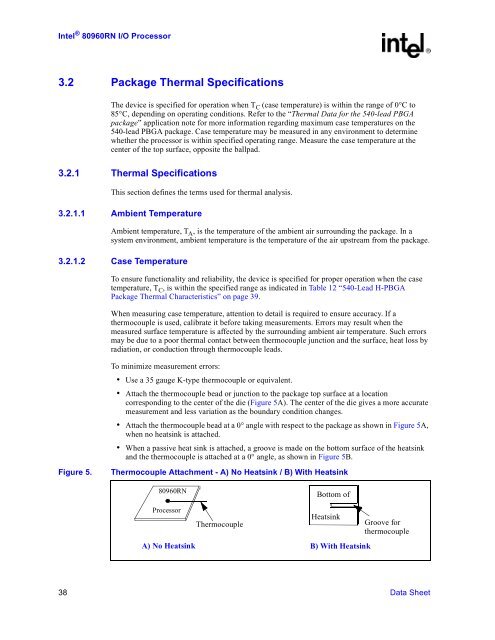
• Attach the thermocouple bead or junction to the package top surface at a location<br />
corresponding to the center of the die (Figure 5A). The center of the die gives a more accurate<br />
measurement and less variation as the boundary condition changes.<br />
• Attach the thermocouple bead at a 0° angle with respect to the package as shown in Figure 5A,<br />
when no heatsink is attached.<br />
• When a passive heat sink is attached, a groove is made on the bottom surface of the heatsink<br />
and the thermocouple is attached at a 0° angle, as shown in Figure 5B.<br />
Figure 5.<br />
Thermocouple Attachment - A) No Heatsink / B) With Heatsink<br />
<strong>80960</strong><strong>RN</strong><br />
Bottom of<br />
<strong>Processor</strong><br />
Thermocouple<br />
Heatsink<br />
Groove for<br />
thermocouple<br />
A) No Heatsink B) With Heatsink<br />
38 Data Sheet