

View - IEEE Xplore
View - IEEE Xplore
View - IEEE Xplore

Create successful ePaper yourself
Turn your PDF publications into a flip-book with our unique Google optimized e-Paper software.
<strong>IEEE</strong> TRANSACTIONS ON ANTENNAS AND PROPAGATION, VOL. 53, NO. 10, OCTOBER 2005 3403<br />
An Ultrawide-Band Double Discone Antenna With the<br />
Tapered Cylindrical Wires<br />
Ki-Hak Kim, Jin-U Kim, and Seong-Ook Park<br />
Abstract—A novel double discone antenna is composed of the asymmetric<br />
biconical antenna and upside-down discone antenna. The asymmetric<br />
biconical antenna has all-wire structure like octopus legs for covering<br />
at lower operating frequency, and the upside-down discone antenna has<br />
conical shape playing a role as covering at higher operating frequency.<br />
An elaborate assembly of two antenna exhibits a 1:100 impedance bandwidth<br />
(180 MHz–18 GHz) with VSWR below 2.5 while maintaining an<br />
acceptable omnidirectional radiation pattern except at about 12 GHz<br />
region. The simulated performances of the proposed antenna are verified<br />
by the measured results of the fabricated antenna. There seems to be good<br />
agreement with each other. These features make such antennas highly<br />
suitable for application to UWB system.<br />
Index Terms—Asymmetric biconical antenna, double discone antenna.<br />
I. INTRODUCTION<br />
The development of the ultrawide-band (UWB) system has brought<br />
about rapid growth of broad band antenna techniques. Since UWB<br />
antennas have typically been designed with specifications that include<br />
constant gain and linear phase response, it is necessary to modify the<br />
existing antenna model or develop a new wide band antenna. Among<br />
existing UWB antennas such as biconical, discone, double-ridged<br />
waveguide horn, and log-periodic antenna, the discone antenna is typical<br />
antennas used for UWB systems. First, the biconical antenna has<br />
good performance if the dimension is infinite, but practical antennas<br />
should be finite structure. The general dimension of the biconical<br />
antenna is about a half wavelength of cutoff frequency, so it has disadvantages<br />
in terms of size. Second, the double-ridged waveguide horn<br />
and log-periodic antenna have a directional radiation pattern. Finally,<br />
even though the discone antenna has an omnidirectional radiation<br />
patternand relatively small size, its radiationpatternis tilted down<br />
due to the asymmetric structure [1]–[4] and [8].<br />
Therefore, this paper describes and analyzes the novel ultrawide-band<br />
double discone antenna for UWB systems. The antenna<br />
presented in this paper is a combination of the asymmetric biconical<br />
and upside-down discone antennas. The proposed antenna has a<br />
structure of radial wires to reduce weight and wind resistance. The<br />
performances of the proposed antenna are similar to those of the<br />
discone antenna even though it is constructed like the asymmetric<br />
biconical antenna. The upside-down discone is used for higher sections<br />
above 1.5 GHz [1]. This upside-down discone is similar to<br />
conical antennas mounted on the finite ground plane [2]. The upper<br />
radial wires of the proposed antenna have a long tapered cylindrical<br />
shape to obtain better performance of VSWR. The antenna is coupled<br />
with a feed coaxial waveguide, where only the TEM mode is<br />
excited. As a result, the proposed antenna exhibits broader impedance<br />
bandwidth. In this paper, details of the antenna design are described,<br />
and the simulated and measured results are presented to show the<br />
validity of the proposed antenna. To understand the behavior of the<br />
Manuscript received November 4, 2004; revised April 28, 2005. This work<br />
was supported by the Ministry of National Defense, Republic of Korea, Dual<br />
Use Technology Program under Contract 2EN0300.<br />
The authors are with the School of Engineering, Information and Communications<br />
University, Daejeon 305-732, Korea (e-mail: kkh8166@icu.ac.kr;<br />
jinu@icu.ac.kr; sopark@icu.ac.kr).<br />
Digital Object Identifier 10.1109/TAP.2005.856036<br />
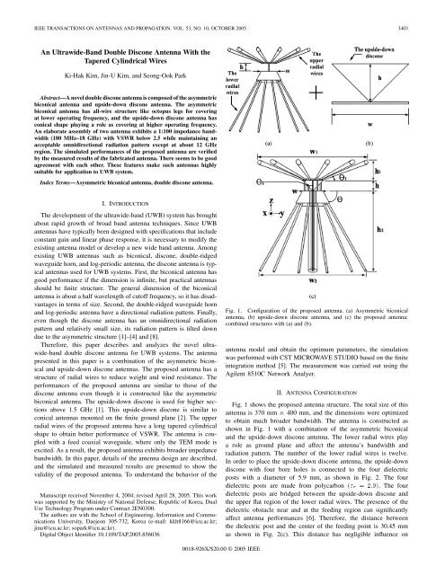
Fig. 1. Configuration of the proposed antenna. (a) Asymmetric biconical<br />
antenna, (b) upside-down discone antenna, and (c) the proposed antenna:<br />
combined structures with (a) and (b).<br />
antenna model and obtain the optimum parameters, the simulation<br />
was performed with CST MICROWAVE STUDIO based onthe finite<br />
integration method [5]. The measurement was carried out using the<br />
Agilent 8510C Network Analyer.<br />
II. ANTENNA CONFIGURATION<br />
Fig. 1 shows the proposed antenna structure. The total size of this<br />
antenna is 370 mm 2 400 mm, and the dimensions were optimized<br />
to obtain much broader bandwidth. The antenna is constructed as<br />
shown in Fig. 1 with a combination of the asymmetric biconical<br />
and the upside-down discone antenna. The lower radial wires play<br />
a role as ground plane and affect the antenna’s bandwidth and<br />
radiation pattern. The number of the lower radial wires is twelve.<br />
In order to place the upside-down discone antenna, the upside-down<br />
discone with four bore holes is connected to the four dielectric<br />
posts with a diameter of 5.9 mm, as showninFig. 2. The four<br />
dielectric posts are made from polycarbon ("r =2:9). The four<br />
dielectric posts are bridged between the upside-down discone and<br />
the upper flat regionof the lower radial wires. The presence of the<br />
dielectric obstacle near and at the feeding region can significantly<br />
affect antenna performances [6]. Therefore, the distance between<br />
the dielectric post and the center of the feeding point is 30.45 mm<br />
as shown in Fig. 2(c). This distance has negligible influence on<br />
0018-926X/$20.00 © 2005 <strong>IEEE</strong>
3404 <strong>IEEE</strong> TRANSACTIONS ON ANTENNAS AND PROPAGATION, VOL. 53, NO. 10, OCTOBER 2005<br />
TABLE I<br />
DESIGN PARAMETERS OF THE PROPOSED ANTENNA<br />
Fig. 3. Experimented antenna configuration. (a) Disk plate, (b) uniform<br />
cylindrical wires, and (c) tapered cylindrical wires (proposed antenna).<br />
Fig. 2. Feeding structure of the proposed antenna. (a) Photograph of the<br />
antenna, (b) enlarged drawing of the feeding structure, and (c) top view of<br />
Fig. 2(b).<br />
antenna characteristics. Fig. 2(b) shows a feeding structure in which<br />
the inner conductor of the N-type jack connector is attached to and<br />
penetrates into the center of the upside-down discone. Finally, the<br />
feeding structure is fixed firmly with dielectric posts and an N-type<br />
jack connector. Fig. 1(b) shows the structure of an upside-down<br />
discone. The height h, angle 2 , and width w of the upside-down<br />
discone are optimized to maximize the bandwidth ratio and gain.<br />
Input impedances of the proposed antenna are governed by the<br />
half-cone angle 2 of the upside-downdiscone [3]. The upper flat<br />
regionof the lower radial wires and the disk of the upside-down<br />
discone have the same width with the dimension of w =70mm.<br />
The upper radial wires (twelve wires) influence bandwidth, gain, and<br />
radiation patterns [7]. In order to obtain good performances as well<br />
as reduce antenna size, the angle 1 was optimized to 20 degrees<br />
inFig. 1(c). The tapered cylindrical wires are modified from the<br />
conventional discone antenna’s disk [1]. The tapered cylindrical<br />
wires allow the input impedance to have a broader bandwidth. If<br />
a disk plate is used in the proposed antenna instead of the upper<br />
radial wires, the performances of the antenna are not good due to<br />
the coupling effect or the reflected wave between the upside-down<br />
discone and disk plate, as shown in Fig. 4. In this structure, the<br />
ultrawide bandwidth can be achieved by properly choosing a location<br />
of the four dielectric posts, , and 1 of the antenna. Furthermore, by<br />
continuously adjusing the height h and angle 2 of the upside-down<br />
discone, it is possible to tune the impedance matching level. As a<br />
result, the modified antenna has an upside-down discone and tapered<br />
cylindrical wires. This results in a broader VSWR than that of the<br />
conventional UWB antennas. The associated antenna parameters for<br />
achieving optimum performance are given in Table I.<br />
Fig. 4. Comparisons of the measured VSWR among the antennas having disk<br />
plate, uniform cylindrical wires, and tapered cylindrical wires, respectively.<br />
Fig. 5. Comparisons of the measured and simulated VSWR for the proposed<br />
antenna.<br />
III. RESULTS<br />
A. VSWR<br />
Fig. 4 shows the results of VSWR among tapered cylindrical wires,<br />
uniform cylindrical wires, and the disk plate, respectively. As seen<br />
in Fig. 4, the dashed line, thin solid line, and thick solid line denote<br />
the VSWR values of Fig. 3(a), Fig. 3(b), and Fig. 3(c), respectively.
<strong>IEEE</strong> TRANSACTIONS ON ANTENNAS AND PROPAGATION, VOL. 53, NO. 10, OCTOBER 2005 3405<br />
Fig. 7.<br />
Measured and simulated antenna gains.<br />
TABLE II<br />
ANGLES OF THE MEASURED MAXIMUM GAIN IN FIG. 6<br />
uniform cylindrical wires in Fig. 3(b) does not satisfy VSWR < 2:5<br />
in the vicinity of 13 GHz and 18 GHz. The antenna of Fig. 3(a) only<br />
satisfies bandwidth up to 4.3 GHz.<br />
The measured and simulated VSWR of the proposed antenna are<br />
showninFig. 5. As showninFig. 5, the simulated and measured VSWR<br />
patterns seem to be in good agreement with each other. However, there<br />
are slight discrepancies between these results, due to mechanical inaccuracies<br />
and feeding problems from the jack adaptor, which were not<br />
considered in the simulation. From these results, it can be demonstrated<br />
that the proposed antenna has a broader VSWR over 100 to 1 bandwidth<br />
without using the impedance matching tuner.<br />
Fig. 6. Simulated and measured E-plane radiation patterns: (a) 0.5 GHz,<br />
(b) 0.7 GHz, (c) 1 GHz, (d) 2 GHz, (e) 3 GHz, (f) 4 GHz, (g) 8 GHz, (h) 12 GHz,<br />
(i) 15 GHz, and (j) 18 GHz ( measured results; ......simulated results).<br />
The measured VSWRs of the proposed antenna in Fig. 3(c) have<br />
180 MHz18 GHz (VSWR < 2:5). However, the antenna having<br />
B. Radiation Patterns and Gains<br />
The measured and simulated radiation patterns of the proposed antenna<br />
in E-planes are shown in Fig. 6. The measured and simulated<br />
results agree well with each other. As showninFig. 6, the radiation<br />
patterns at low frequencies are similar to those of the short dipole. As<br />
the operating frequency increases up to higher frequencies, the patterns<br />
are tilted downward because the upper radial wires and lower radial<br />
wires are an asymmetric structure [7]. However, the downward tilting<br />
phenomenon above 2 GHz is not occured. The proposed antenna offers<br />
satisfactory radiation performance while retaining the omnidirectional<br />
pattern. However, it is clearly observed that the null phenomenon at<br />
angle occurs at 12 GHz in Fig. 6(h). Except for the 12 GHz region, the<br />
omnidirectional pattern of this antenna is maintained.<br />
The measured and simulated gains are shown in Fig. 7. A threeantenna<br />
technique is used to measure the radiation gain. The gain value<br />
has beentakenat angle where the gainis the maximum. Each associated<br />
tilted angle at all frequencies is listed in Table II. The measured gain<br />
error is within 60.5 dBi accuracy. The measured gainabove 1 GHz frequency<br />
range has an average 3 dBi or more. The discrepancies between<br />
the simulated and measured gains can be attributed to the antenna loss<br />
effects and the uncertainty of the simulated results. However, the simulated<br />
and measured gains have a similar tendency.
3406 <strong>IEEE</strong> TRANSACTIONS ON ANTENNAS AND PROPAGATION, VOL. 53, NO. 10, OCTOBER 2005<br />
IV. CONCLUSION<br />
This paper demonstrates a double discone antenna for the UWB<br />
system which is a combination of the asymmetric biconical and upside-down<br />
discone structures. In order to improve VSWR performance,<br />
a tapered cylindrical wire at an angle of 20 was proposed instead of<br />
the disk plate and uniform cylindrical wires. Additionally, four dielectric<br />
posts were employed to place the upside-down discone and lower<br />
radial wires firmly. The performances were verified by the measured<br />
and simulated results of the fabricated prototype antenna. This antenna<br />
exhibited an omnidiectional radiation pattern and relatively small size<br />
while retaining 100:1 impedance bandwidth. The proposed double discone<br />
antenna with tapered cylindrical wires has a wider bandwidth performance,<br />
when compared to that of any existing conventional UWB<br />
antennas. These features make the proposed antenna very suitable for<br />
UWB system antennas and radio frequency monitoring.<br />
ACKNOWLEDGMENT<br />
The authors would like to thank the two anonymous reviewers for<br />
their comments which improved this paper.<br />
REFERENCES<br />
[1] J. U. Kim and S. O. Park, “Novel ultra-wideband discone antenna,” Microw.<br />
Opt. Technol. Lett., vol. 42, pp. 113–115, Jul. 2004.<br />
[2] G. Liu and C. A. Grimes, “Spherical-coordinate FDTD analysis of conical<br />
antennas mounted above finite ground plane,” Microw. Opt. Technol.<br />
Lett., vol. 23, pp. 78–82, Oct. 1999.<br />
[3] J. D. Kraus, Antennas, 2nd ed. New York: McGraw-Hill, 1998, pp.<br />
692–694.<br />
[4] T. Taniguchi and T. Kobayashi, “An omnidirectional and low-VSWR<br />
antenna for the FCC-approved UWB frequency band,” in Proc. <strong>IEEE</strong><br />
Antennas Propagat. Symp., Jun. 2003, pp. 460–463.<br />
[5] “Computer SimulationTechnology (CST) Microwave Studio,” ver. 4.2<br />
Available: www.cst.com.<br />
[6] R. Stovall and K. Mei, “Application of a unimoment technique to a biconical<br />
antenna with inhomogeneous dielectric loading,” <strong>IEEE</strong> Trans.<br />
Antennas Propag., vol. 23, no. 3, pp. 335–342, May 1975.<br />
[7] K. Nagasawa and I. Matsuzuka, “Radiation field consideration of biconical<br />
horn antenna with different flare angles,” <strong>IEEE</strong> Trans. Antennas<br />
Propag., vol. 36, no. 9, pp. 1306–1310, Sep. 1988.<br />
[8] J. R. Bergmann, “On the design of broadband omnidirectional compact<br />
antennas,” Microw. Opt. Technol. Lett., vol. 39, pp. 418–422, Dec. 2003.<br />
Beam Focusing Properties of Circular Monopole Array<br />
Antenna on a Finite Ground Plane<br />
Satish Kumar Sharma and Lotfollah Shafai<br />
Abstract—This paper presents the investigation results on the beam focusing<br />
properties of a wire circular monopole array (CMA) antenna consisting<br />
of six-elements on a finite ground plane, by exciting more than one<br />
monopole at a time. The excitation of more than one element provides enhanced<br />
horizontal and vertical plane peak directivities, and a reduced 3 dB<br />
beamwidth for the horizontal pattern. The effect of varying the number of<br />
monopole elements in the array is also discussed, when only one element<br />
is excited, and the remaining ones are shorted to the ground. The antenna<br />
was fabricated and tested for its impedance and radiation characteristics<br />
for one of the excitation schemes, and the results were found in reasonable<br />
agreement with the simulations.<br />
Index Terms—Beam focusing properties, circular monopole array<br />
(CMA), finite ground, multiple excitations.<br />
I. INTRODUCTION<br />
Monopole antennas are widely used in mobile wireless communications,<br />
because of their simplicity and broad-band characteristics<br />
[1], [2]. In terrestrial multipath loss environments, the horizontal<br />
plane sector beams need narrow beamwidths, so that least inter-sector<br />
interference is present [3]. One way to generate the narrow beam is<br />
to excite one element of a circular array (Fig. 1), while keeping the<br />
remaining ones passive to behave as a reflector [4]. This is similar<br />
to the corner reflectors, where by adjusting the angle between the<br />
corners, the beamwidth and directivity can be controlled [3]. In [5],<br />
[6], electronically steerable switched parasitic arrays, for the base-station<br />
tracking in mobile communications, employing a directional<br />
array with only one active element and three parasitic elements were<br />
presented. In [7], authors presented a historical survey of switched<br />
parasitic antennas and various ways of generating switched beams by<br />
employing different number of wire elements in the arrays. In [8],<br />
authors presented a six-element circular switched monopole array on<br />
an infinite ground plane for beam steering in the azimuth or horizontal<br />
plane. It provided a directivity of 10.8 dBi at the beam peak by exciting<br />
two elements simultaneously, while shorting the remaining ones to<br />
the ground. In [9], a seven-element electrically steerable passive array<br />
radiator (ESPAR) was designed to enhance its horizontal gain by using<br />
a skirt on a circular ground plane, which showed a gain of 8.00 dBi in<br />
both E- and H-planes. In [10], [11], a few initial investigation results,<br />
on the antenna discussed in this paper, were presented.<br />
Incertainapplications directive beams are required inboth elevation<br />
and horizontal planes, with different beam characteristics. The L-band<br />
digital radio broadcast (DRB) is one such case, simultaneously broadcast<br />
from a geostationary satellite and ground stations. A mobile vehicle<br />
may access either, depending on the signal strength. However, the<br />
satellite elevation angles depend on the geographical location, and for<br />
southern regions of Canada, the elevation angles between 30 to 40 <br />
are the most likely satellite directions, where the mobile antenna must<br />
be aimed. On the other hand, for the terrestrial stations, both mobile<br />
and the transmitter antennas are in the horizontal plane, where the antenna<br />
gain, and the front-to-back (F/B) ratio, must be sufficient to allow<br />
signal reception and discrimination in the multipath loss environment.<br />
0018-926X/$20.00 © 2005 <strong>IEEE</strong><br />
Manuscript received November 27, 2003; revised April 22, 2005.<br />
The authors are with the Department of Electrical and Computer Engineering,<br />
The University of Manitoba, Winnipeg, Manitoba R3T 5V6, Canada (e-mail:<br />
sharma@ee.umanitoba.ca; shafai@ee.umanitoba.ca).<br />
Digital Object Identifier 10.1109/TAP.2005.856376


