DNP V3.00 - Landis+Gyr
DNP V3.00 - Landis+Gyr
DNP V3.00 - Landis+Gyr

You also want an ePaper? Increase the reach of your titles
YUMPU automatically turns print PDFs into web optimized ePapers that Google loves.
<strong>Landis+Gyr</strong> Inc.<br />
Implementation of<br />
<strong>DNP</strong> <strong>V3.00</strong> Protocol Level 2 & 3<br />
Document Number MKB-524011500<br />
Revision D
Implementation of<br />
<strong>DNP</strong> <strong>V3.00</strong> Protocol Level 2 & 3<br />
Document Number MKB-524011500<br />
Revision D<br />
CONFIDENTIAL<br />
This material is the property of <strong>Landis+Gyr</strong> Inc. To be returned<br />
upon request. Not to be copied, reproduced, loaned, or<br />
otherwise disposed of directly or indirectly. It contains<br />
confidential proprietary information to be used only for<br />
reference, installation, and maintenance of equipment or other<br />
dealings with this company. Further use, without written<br />
permission first obtained, is not authorized.
Information in this document is subject to change without notice. No part of this document may<br />
be reproduced or transmitted in any form or by any means, electronic or mechanical, for any<br />
purpose without the express written permission of <strong>Landis+Gyr</strong> Inc.<br />
© 1997 <strong>Landis+Gyr</strong> Inc.<br />
All rights reserved.<br />
For further information, contact:<br />
<strong>Landis+Gyr</strong> Inc. Tel: 765-742-1001<br />
Meter Division Toll Free: 800-777-2774<br />
2800 Duncan Road Fax: 765-429-1326<br />
Lafayette, In 47904-5012 USA Website: www.LandisGyr.us<br />
ii
iii
Document History<br />
Title: Implementation of <strong>DNP</strong> <strong>V3.00</strong> Protocol Level 2 & 3<br />
Document Number:<br />
MKB-524011300<br />
Revision<br />
Level<br />
Date<br />
Issued<br />
Description<br />
of Revision<br />
Original 5/24/01 Initial issue.<br />
Revision A<br />
Revision B<br />
Revision C<br />
Revision D<br />
8/02/01<br />
7/08/02<br />
11/18/02<br />
3/12/03<br />
Add set-up information on all protocol board jumpers<br />
Table 50 set-up and defaults<br />
Additional error code information Updated Device Profile<br />
Removed unsolicited responses for certification<br />
iv
TABLE OF CONTENTS<br />
1 Communications......................................................................................... 1<br />
1.1 Baud Rate ......................................................................................................... 1<br />
1.2 UART setup ...................................................................................................... 1<br />
1.3 Data Link Layer Services ................................................................................. 1<br />
1.3.1 Data Link Confirmations ...........................................................................................1<br />
1.3.2 Data Link Retries.......................................................................................................1<br />
1.3.3 Collision Avoidance...................................................................................................1<br />
1.3.4 Data Link Layer Transport Receive Buffer................................................................2<br />
1.3.5 Data Link Layer Transport Transmit Buffer...............................................................2<br />
1.4 Time Synchronization ..................................................................................... 2<br />
2 Data Point Mapping.................................................................................... 3<br />
2.1 Binary Inputs .................................................................................................... 3<br />
2.1.1 Error Status Bits........................................................................................................3<br />
2.1.2 Status Input Bits .......................................................................................................3<br />
2.1.3 Relay Output Status..................................................................................................3<br />
2.2 Binary Outputs ................................................................................................. 4<br />
2.3 Analog Inputs ................................................................................................... 4<br />
2.4 Analog Outputs................................................................................................ 5<br />
2.5 Binary Counter Inputs ..................................................................................... 5<br />
2.5.1 Register Data ............................................................................................................5<br />
3 Event Storage.............................................................................................. 6<br />
3.1 Binary Input Change Events ........................................................................... 6<br />
3.2 Analog Input Change Events .......................................................................... 6<br />
3.2.1 Analog Dead Band ....................................................................................................6<br />
3.3 Binary Counter Change Events....................................................................... 7<br />
4 Object and Variation Support.................................................................... 8<br />
4.1 Object 1 – Binary Input Object (Static) .......................................................... 8<br />
4.2 Object 2 – Binary Input Change Object (Event) ............................................ 8<br />
4.3 Object 10 – Binary Output Object (Static) ..................................................... 8<br />
4.4 Object 12 – Control Block Object (Static)...................................................... 8<br />
4.5 Object 20 – Binary Counter Object (Static) ................................................... 8<br />
4.6 Object 21 – Frozen Counter Object (Frozen Static) ...................................... 8<br />
4.7 Object 22 – Counter Change Event Object (Event)....................................... 9<br />
4.8 Object 23 – Frozen Counter Event Object (Frozen Event)............................ 9<br />
4.9 Object 30 – Analog Input Object (Static)....................................................... 9<br />
4.10 Object 31 – Frozen Analog input Object (Frozen Static)........................... 9<br />
4.11 Object 32 – Analog Change Event Object (Event) ..................................... 9<br />
4.12 Object 33 – Frozen Analog Event Object (Frozen Event) ........................ 10<br />
4.13 Object 34 – Analog Event Deadband Object............................................ 10<br />
v
4.14 Object 40 – Analog Output Status Object (Static) .................................. 10<br />
4.15 Object 41 – Analog Output Block Object (Static) .................................... 10<br />
4.16 Object 50 – Time and Date Object ............................................................ 10<br />
4.17 Object 51 – Time and Date CTO Object.................................................... 10<br />
4.18 Object 52 – Time Delay Object .................................................................. 10<br />
4.19 Object 60 – Class Data Object ................................................................... 10<br />
4.20 Object 70 – File Object ............................................................................... 10<br />
4.21 Object 80 – Internal Indications Object .................................................... 11<br />
4.22 Objects 81 and Above ................................................................................ 11<br />
5 Power Up and System Initialization........................................................ 12<br />
5.1 First Power Up................................................................................................ 12<br />
5.2 Power Fail ....................................................................................................... 12<br />
5.3 Idle Mode........................................................................................................ 12<br />
6 LED’s .......................................................................................................... 13<br />
6.1 Error Codes..................................................................................................... 13<br />
6.1.1 Error Code 11 – Meter Comm Error .......................................................................13<br />
6.1.2 Error Code 12 – <strong>DNP</strong> Host Comm Error .................................................................13<br />
6.1.3 Error Codes 13, 14 & 15 – <strong>DNP</strong> Host Comm Errors...............................................14<br />
6.1.4 Error Code 21 – Watchdog Timer Fail.....................................................................14<br />
6.1.5 Error Codes 22, 23, 24 & 25 – Internal Configuration Errors..................................14<br />
6.1.6 Error Code 31 – Meter Idle .....................................................................................14<br />
6.1.7 Error Code 32 – Invalid Table 0...............................................................................14<br />
6.1.8 Error Code 33 – Invalid Table 32.............................................................................14<br />
6.1.9 Error Code 34 – EEPROM Failure...........................................................................14<br />
6.1.10 Error Code 4X – Internal Stack Overflow................................................................14<br />
6.1.11 Error Code 5X – Trace Buffer Alert .........................................................................14<br />
6.2 Error Code Display ......................................................................................... 14<br />
7 Mapper Set-up .......................................................................................... 16<br />
7.1 Display Configuration.................................................................................... 16<br />
7.1.1 Master Display Choices: .........................................................................................16<br />
7.1.2 Port RS232 List:......................................................................................................16<br />
7.1.3 List Selection: .........................................................................................................16<br />
7.1.4 Scale Factors:..........................................................................................................16<br />
7.1.5 Ports Button:...........................................................................................................17<br />
7.2 Port Configuration 1(Display Lists, Binary Input List & Analog Data) ...... 17<br />
7.2.1 Displays Lists (Analog or counter values to be returned to the host.) ...................17<br />
7.2.2 Binary Input List (Errors, Input or Relay status reported back to host.) .................17<br />
7.2.3 Analog Data.............................................................................................................17<br />
7.3 Port Configuration 2 (Counter Data, Event Data Storage & Relay Outputs)<br />
18<br />
7.3.1 Counter Data...........................................................................................................18<br />
7.3.2 Event Data ..............................................................................................................18<br />
7.3.3 Relay Outputs .........................................................................................................19<br />
7.4 Port Configuration 3 (Unsolicited Responses & Collision Avoidance) ..... 19<br />
7.4.1 Unsolicited Responses ...........................................................................................20<br />
7.4.2 Collision Avoidance.................................................................................................20<br />
vi
7.5 Port Configuration 4 (Data Link Layer & Baud Rate) .................................. 20<br />
7.5.1 Data Link Layer .......................................................................................................21<br />
7.5.2 Baud Rate ...............................................................................................................21<br />
7.5.3 Extended Configuration ..........................................................................................21<br />
7.6 Port Configuration 5 Extended <strong>DNP</strong> Configuration (Table 50) .................. 21<br />
7.6.1 Default Variations....................................................................................................22<br />
7.7 Port Configuration 6 Extended <strong>DNP</strong> Configuration (Table 50) ................. 22<br />
7.7.1 Pre Transmit Delay .................................................................................................23<br />
7.7.2 Post Transmit Delay................................................................................................23<br />
7.7.3 Time Sync Request & Time Sync Period................................................................23<br />
7.7.4 Time Sync Request & Time Sync Period................................................................24<br />
7.7.5 Freeze Minutes.......................................................................................................24<br />
7.8 Port Configuration 7 Extended <strong>DNP</strong> Configuration (Table 50) .................. 24<br />
7.8.1 Data Point Configurations .......................................................................................25<br />
8 Maxcom Set-up Program Mode .............................................................. 25<br />
8.1 Download list - Port Configuration .............................................................. 25<br />
8.1.1 Baud Rate ...............................................................................................................25<br />
8.1.2 Device Address.......................................................................................................25<br />
8.1.3 Host Address ..........................................................................................................25<br />
8.1.4 Collision Detection / Avoidance & Delays...............................................................26<br />
8.1.5 Unsolicited Responses, Timeouts & Retries..........................................................26<br />
8.1.6 Data Link Layer, Confirmations & Retries ..............................................................26<br />
8.1.7 Counter & Analog Data Size ...................................................................................26<br />
8.1.8 Analog Dead Band %:.............................................................................................26<br />
8.1.9 Include Display Lists ...............................................................................................26<br />
9 Maxcom Edit Program Mode................................................................... 27<br />
9.1 Edit Mode List - Port Configuration ............................................................. 27<br />
9.1.1 Edit Variables: .........................................................................................................27<br />
10 Maxcom Data Collection Mode ............................................................ 28<br />
10.1 Table RS232 Data Collection Mode .......................................................... 28<br />
10.1.1 Mode:......................................................................................................................28<br />
10.1.2 Flag: ........................................................................................................................29<br />
10.1.3 Value: ......................................................................................................................30<br />
10.1.4 Baud:.......................................................................................................................30<br />
10.1.5 Gen: ........................................................................................................................30<br />
10.1.6 Table : .....................................................................................................................31<br />
10.1.7 Output Type:...........................................................................................................31<br />
11 Hardware ................................................................................................ 32<br />
11.1 Protocol Converter Board .......................................................................... 32<br />
11.1.1 Jumper Installations Protocol Board.......................................................................32<br />
11.2 Display Board .............................................................................................. 34<br />
11.2.1 Jumper Installations Display Board ........................................................................35<br />
12 Device Profile Document....................................................................... 36<br />
13 <strong>DNP</strong> 3.00 Implementation Table........................................................... 41<br />
<strong>DNP</strong> 3.00 - IMPLEMENTATION TABLE ................................................................... 41<br />
vii
1 Communications<br />
The <strong>DNP</strong> protocol converter card supports RS232 and two-wire RS485 communications. The<br />
standard <strong>DNP</strong> data link layer and application layer services are supported.<br />
1.1 Baud Rate<br />
There are seven-baud rates supported. The protocol converter card always communicates with<br />
the meter at 9600 baud. However, the protocol converter card can be configured through table<br />
32 to communicate with the <strong>DNP</strong> host at 300, 600, 1200, 2400, 4800, 9600, or 19200 baud.<br />
1.2 UART setup<br />
The parity, number of data bits, and number of stop bits are fixed at none, 8, and 1 respectively.<br />
These parameters are not adjustable.<br />
1.3 Data Link Layer Services<br />
The <strong>DNP</strong> firmware supports data link confirmations, data link retries, and collision avoidance, all<br />
as configurable parameters in table 32.<br />
1.3.1 Data Link Confirmations<br />
The <strong>DNP</strong> firmware can be configured to request data link confirmations on all primary messages<br />
that are sent. This is a data link layer service and is transparent to the application layer. This<br />
service provides a level of guaranteed delivery for all primary data link frames to the host. This<br />
parameter works with the data link retries parameter (see next section).<br />
This service is configured through table 32.<br />
1.3.2 Data Link Retries<br />
The <strong>DNP</strong> firmware can be configured to retry unconfirmed data link primary frames. The retry is<br />
attempted when the confirmation has not arrived within 300 milliseconds after sending the<br />
primary frame. The 300-millisecond timeout is fixed. Retries are not attempted unless data link<br />
confirmations are enabled.<br />
The number of retries is fixed at 2 if they are enabled. If the confirmation fails after two retries,<br />
the communication link is considered failed, and a reset sequence is required before a new<br />
primary frame can be sent.<br />
This service is configured through table 32.<br />
1.3.3 Collision Avoidance<br />
The <strong>DNP</strong> firmware can be configured to enable or disable collision avoidance through table 32.<br />
The collision avoidance method used is “Detection of Transmitted Data”. The back-off algorithm<br />
used is defined in the <strong>DNP</strong> Basic 4 documentation set. The fixed delay is taken from the bottom<br />
byte of the meter’s <strong>DNP</strong> address. This value is multiplied by 10 milliseconds to arrive at the<br />
fixed delay portion of the back-off time. The maximum random delay in units of 10’s of<br />
milliseconds is a configurable parameter stored in table 32.<br />
Collision avoidance should never be enabled on a point-to-point connection since the algorithm<br />
inserts additional delays in the transmit state machine. Also, if there are no <strong>DNP</strong> end devices<br />
that send unsolicited responses attached to the communication line, then collisions are<br />
impossible and collision avoidance should be disabled.<br />
1
1.3.4 Data Link Layer Transport Receive Buffer<br />
The data link layer can string several frames together (each one being a transport segment)<br />
before reporting the entire data buffer to the application layer. This is referred to as the <strong>DNP</strong><br />
transport function.<br />
The data link layer maintains one transport buffer of 1024 bytes dedicated to receiving host<br />
primary messages. The <strong>DNP</strong> application layer also maintains a second buffer that it uses to<br />
operate on received data. The <strong>DNP</strong> firmware can thus receive two 1024 byte messages from<br />
the host in rapid succession without rejecting the data. A third message would be “NAK’d”<br />
unless the application layer could dispatch one or both of the previous messages before the first<br />
frame of the third message arrived.<br />
1.3.5 Data Link Layer Transport Transmit Buffer<br />
The data link layer does not maintain a transport buffer for sending application layer fragments.<br />
However, the application layer maintains two 2048 byte fragment buffers so that it can build a<br />
new response message while the data link layer is busy sending a previously generated<br />
response message.<br />
The data link layer will break up the 2048 byte application layer fragment into several transport<br />
segments and send them to the host one frame at a time.<br />
1.4 Time Synchronization<br />
Time synch is available through the <strong>DNP</strong> protocol. The meter’s time may be modified only<br />
within the restrictions of the “Modify Clock Time” X command (X 13). This command allows the<br />
meter time to be changed within the range of –32768 to +32767 seconds (roughly +/- 9 hours).<br />
In no case however can the clock be modified to cross a midnight boundary.<br />
2
2 Data Point Mapping<br />
The <strong>DNP</strong> protocol defines three major types of data points: binary, analog, and counter. Of<br />
those three, the binary and analog types can be inputs or outputs. The counter type is always an<br />
input. All of the above types are supported in the MAXsys and Quad4+ meters with the<br />
exception of analog outputs.<br />
2.1 Binary Inputs<br />
Binary inputs are fully supported. The number of binary inputs available to a meter is dependent<br />
on the specific version of firmware, but all versions have some of each of the following types.<br />
2.1.1 Error Status Bits<br />
All versions keep an error status word. This word contains 4 bits that may be of interest to the<br />
user. The error status bits are configurable as a group, that is, either all four are configured in, or<br />
none are. If the error bits are configured in, then they map to binary points 0 through 3 as<br />
follows:<br />
0 RAM Failure<br />
1 Program Malfunction<br />
2 ROM Failure<br />
3 Recording<br />
The error status bits are taken from Table 3, unit_status, bits 0, 3, 4, and 10.<br />
2.1.2 Status Input Bits<br />
All meter versions have some number of status inputs. The actual number is defined in Table 0<br />
under the name MAX_SENSE_INPUTS. A typical number of status inputs is 11. As with the<br />
error status bits, the status input bits are configurable as a group. All status inputs are<br />
configured in, or none are. If the error bits are configured in, then the first status input binary<br />
data point is 4. If the error status bits are not mapped, then the first status input is mapped to<br />
binary data point 0.<br />
Note: Typically the first status input is phase C presence, followed by phases B then A, and all<br />
other status inputs are unused. However, if any of the meter’s Aux Inputs have been<br />
programmed as status inputs, then the lowest number Aux Input becomes the first status input,<br />
followed by all remaining aux inputs. The phase presence indicators are tacked on to the end of<br />
the list after the last aux input.<br />
The status input bits are taken from Table 3, sense_input_status, bits 0 through<br />
MAX_SENSE_INPUTS–1.<br />
2.1.3 Relay Output Status<br />
All meter versions also have some number of relay outputs. The actual number is defined in<br />
Table 0 under the name MAX_OUTPUTS. A typical number of relay outputs is 12. These should<br />
not be confused with binary outputs, which are also available. The entire lot of relays are<br />
available as inputs because under many circumstances, they are used as alarms, and therefore<br />
behave as inputs.<br />
3
As with the error status bits and the status input bits, the relay status bits are configurable as a<br />
group. All relay output status bits are configured in, or none are. The starting number of the first<br />
relay status binary data point is dependent upon whether the error bits and status bits have been<br />
configured in. The table below shows the starting position based on other bit inclusion:<br />
Errors Included Status Inputs Included<br />
Relay 1 binary data point number<br />
No No 0<br />
Yes No 4<br />
No Yes MAX_SENSE_INPUTS<br />
Yes Yes MAX_SENSE_INPUTS + 4<br />
The relay output status bits are taken from Table 3, output_status, bits 0 through<br />
MAX_OUTPUTS–1.<br />
2.2 Binary Outputs<br />
Binary outputs are also fully supported. Binary outputs are, of course, the relay outputs. The<br />
number of relay outputs available to a meter is dependent upon the specific version of firmware.<br />
Binary outputs are configured in as a group, just like the binary inputs. Meter relay 1<br />
corresponds with binary output point 0, and so on up to the number of relays defined in table 0.<br />
In order for relay outputs to be available to the <strong>DNP</strong> host, two configuration requirements must<br />
be satisfied. First, the relay control type must be configured in table 32. This configuration<br />
specifies the control methodology for the relays: Select Before Operate, Direct Operate with<br />
Acknowledgement, or Direct Operate, No ACK. If none of these is selected, then no binary<br />
output data points will exist.<br />
Second, any relay that will be actually operated by the <strong>DNP</strong> host must be programmed in Table<br />
19 as being sourced from the Miscellaneous Buss, with the line corresponding to the “Operate<br />
relay via X command”. The actual miscellaneous buss line number is different from meter<br />
version to meter version.<br />
If any relay output is programmed other than “Operate relay via X command”, then the local flag<br />
will be set on in the internal indications word. Only if all of the meter’s relays are programmed<br />
for control via X command will the local flag be cleared in the internal indications.<br />
Note: There is no restriction on the configuration of relays as inputs and outputs. Relays may be<br />
included in the binary input list independently of their inclusion in the binary output list. Relays<br />
can be defined as inputs, outputs, both, or neither.<br />
2.3 Analog Inputs<br />
Analog inputs are also fully supported. These values trace their source back to table 3, either<br />
from the rate_projection array, or the latest_rates array. Analog inputs can be read directly from<br />
table 3, or taken from tables 15 or 36 where rate values are stored in the data blocks. Basically<br />
any rate value is reported back to the <strong>DNP</strong> host as an analog input.<br />
Analog inputs are configured using the external display list in table 32. The mapping of a specific<br />
rate value to a given analog input point is based solely on its relative position in the external<br />
display list. The first rate value found in the list becomes the first analog input data point.<br />
Additional analog input points are assigned as they are found in the display list. They need not<br />
be contiguous in the list, nor do they need to be grouped by table source. Any order of external<br />
display list items is acceptable.<br />
If there is not enough space in table 32 to define all of the required data points, then the external<br />
display lists in table 31 or table 30 can also be used. If the table 31 list is used, then all analog<br />
data points found in that list are tacked onto the <strong>DNP</strong> data point list after the table 32 items.<br />
Likewise, if the table 30 list is used, then all analog data points found in that list are tacked onto<br />
the <strong>DNP</strong> data point list after table 31 items (if any).<br />
4
Analog inputs have a scaling factor applied immediately upon receipt from the meter. The scale<br />
factor, which is a power of 10 from .00000001 to 10000000, is specified in the external display<br />
item list for each individual item.<br />
Analog input values are read from the meter as floating point values, so they must be converted<br />
to 16 or 32 bit signed integers. The conversion process is applied after the value has been<br />
scaled. If the analog value is being converted to a 16-bit integer, then it is divided by 65536.0,<br />
which is 2.0 raised to the 16 th power, and the remainder is reported as the analog value. The<br />
same operation is performed if the analog value is being converted to a 32-bit integer, except<br />
that the divisor is 2.0 raised to the 32 nd power.<br />
2.4 Analog Outputs<br />
Analog outputs are not supported in any way.<br />
2.5 Binary Counter Inputs<br />
Binary counter inputs are also fully supported. These values are basically any register or counter<br />
object in the meter that can be accessed via a display item.<br />
2.5.1 Register Data<br />
Any summation register in the data block array can be configured as a binary counter input.<br />
Other counters include the Table 9 input registers, and some certain values in table 2 and table<br />
3. Basically any data table item that counts anything in the meter can be specified as a binary<br />
counter.<br />
Registers are configured using the external display list in table 32. The mapping of a specific<br />
register to a given binary counter input point is based solely on its relative position in the external<br />
display list. The first register value found in the list becomes the first counter input data point.<br />
The registers need not be contiguous in the list, nor do they need to be grouped by table source.<br />
Any order of external display list items is acceptable.<br />
If there is not enough space in table 32 to define all of the required data points, then the external<br />
display lists in table 31 or table 30 can also be used. If the table 31 list is used, then all counter<br />
data points found in that list are tacked onto the <strong>DNP</strong> data point list after the table 32 items.<br />
Likewise, if the table 30 list is used, then all counter data points found in that list are tacked onto<br />
the <strong>DNP</strong> data point list after table 31 items (if any).<br />
Register values have a scaling factor applied immediately upon receipt from the meter. The<br />
scale factor, which is a power of 10 from .00000001 to 10000000, is specified in the external<br />
display item list for each individual register item. Scale factors specified for binary registers<br />
(such as table 9 input registers) are ignored. The scale factor is applied only to floating point<br />
register values.<br />
Summation register values are read from the meter as floating point values, so they must be<br />
converted to 16 or 32 bit unsigned integers. The conversion process is applied after the value<br />
has been scaled. If the summation register value is being converted to a 16-bit integer, then it is<br />
divided by 65536.0, which is 2.0 raised to the 16 th power, and the remainder is reported as the<br />
register value. The same operation is performed if the summation register value is being<br />
converted to a 32-bit integer, except that the divisor is 2.0 raised to the 32 nd power.<br />
5
3 Event Storage<br />
An important part of the <strong>DNP</strong> protocol involves the ability to record changes in the values of data<br />
points. All static input data types supported can be configured to generate event data.<br />
Event data is stored in a RAM buffer on the protocol converter card. This buffer is approximately<br />
100 Kbytes in length, and allows for a total storage of between 5000 and 6000 events or freeze<br />
data points. The allocation of the buffer space is dynamic and based on the type of data that can<br />
generate events, as well as the number of different data points of each type.<br />
Each data point that can generate events is given a minimum number of buffers for its exclusive<br />
use. Once that minimum is exceeded, then additional buffers are allocated from the general<br />
event buffer allocation until no more event buffer space is available. After that an “any-purpose”<br />
buffer allocation is tapped. The any-purpose buffer space is shared with freeze data events on a<br />
first-come-first-served basis. In any event though, no one data point will be allowed to use up all<br />
of the event data space.<br />
NOTE: The protocol converter card’s buffer memory does not survive a power failure. As<br />
such, unless the meter is powered by an un-interruptible power supply (UPS), no reliance should<br />
be placed on the ability to read event or freeze event data.<br />
3.1 Binary Input Change Events<br />
Binary input change events are fully supported. Each time the binary data point list is updated<br />
with new data, the values that are changed can be recorded along with the time of the change.<br />
Binary input change events are enabled or disabled as a group. If change events are required on<br />
any one binary input, then change events will be recorded on all binary inputs. Binary input<br />
change events are enabled via table 32.<br />
When change events are enabled for binary inputs, each input is guaranteed buffer space for<br />
several change events. Beyond that, each data point competes for buffer space against all other<br />
data points that generate events within the limits defined in section 3.<br />
If binary input change event collection is disabled, then the memory allocation for event storage<br />
is redistributed between event storage and freeze event storage.<br />
3.2 Analog Input Change Events<br />
Analog input change events are fully supported. Each time the analog input data point list is<br />
updated with new data, the values that exceed the analog input dead band can be recorded<br />
along with the time of the change.<br />
Analog input change events are enabled or disabled as a group. If change events are required on<br />
any one analog input, then change events will be recorded on all analog inputs. Analog input<br />
change events are enabled via table 32.<br />
When change events are enabled for analog inputs, each input is guaranteed buffer space for<br />
several change events. Beyond that, each data point competes for buffer space against all other<br />
data points that generate events within the limits defined in section 3.<br />
If analog input change event collection is disabled, then the memory allocation for event storage<br />
is redistributed between event storage and freeze event storage.<br />
3.2.1 Analog Dead Band<br />
Analog data change events rely on a value known as the dead band. This value is the amount of<br />
change required, in the plus or minus direction, that will cause an analog change event to be<br />
generated and stored.<br />
The analog dead band is a global value for all analog inputs, and is configured in table 32 of the<br />
meter. The units are in tenths of a percent, and any value can be selected from 0.0 percent to<br />
6
25.5 percent. A change event is generated when the analog value changes by more than the<br />
dead band percentage from the previously reported change.<br />
3.3 Binary Counter Change Events<br />
Binary counter change events are fully supported. Each time the binary counter data point list is<br />
updated with new data, the values that are changed can be recorded along with the time of the<br />
change.<br />
Binary counter change events are enabled or disabled as a group. If change events are required<br />
on any one binary counter, then change events will be recorded on all binary counters. Binary<br />
counter change events are enabled via table 32.<br />
When change events are enabled for binary counters, each counter is guaranteed buffer space<br />
for several change events. Beyond that, each data point competes for buffer space against all<br />
other data points that generate events within the limits defined in section 3.<br />
If binary counter change event collection is disabled, then the memory allocation for event<br />
storage is redistributed between event storage and freeze event storage.<br />
7
4 Object and Variation Support<br />
This section details the <strong>DNP</strong> objects and variations that are supported.<br />
4.1 Object 1 – Binary Input Object (Static)<br />
This object is read-only. The application layer function codes that apply to this object are:<br />
• Read (1) of variations 0, 1, or 2. Variation 0 read requests are honored with variation 1<br />
response data.<br />
4.2 Object 2 – Binary Input Change Object (Event)<br />
This object is read-only. The application layer function codes that apply to this object are:<br />
• Read (1) of variations 0, 1, 2, or 3. Variation 0 read requests are honored with variation 1<br />
response data.<br />
• Enable Unsolicited Messages (20) of variations 0, 1, 2, or 3. Only one variation may be<br />
specified.<br />
• Disable Unsolicited Messages (21) of any variation.<br />
• Assign Class (22) of variations 1, 2, or 3. Only one variation may be specified.<br />
4.3 Object 10 – Binary Output Object (Static)<br />
This object is read-only. The application layer function codes that apply to this object are:<br />
• Read (1) of variations 0 or 2. Variation 0 read requests are honored with variation 2<br />
response data.<br />
4.4 Object 12 – Control Block Object (Static)<br />
This object is write-only. The application layer function codes that apply to this object are:<br />
• Select (3), Operate (4), Direct Operate (5), and Direct Operate, no ACK (6) may be issued<br />
depending on the table 32 relay output configuration. Only variation 1 is supported.<br />
There is no support for pattern control.<br />
4.5 Object 20 – Binary Counter Object (Static)<br />
This object is read-write. The application layer function codes that apply to this object are:<br />
• Read (1) of variations 0 through 8. Variation 0 read requests are honored with either<br />
variation 5 or variation 6 response data depending on the state of the default counter<br />
size bit in table 32.<br />
• Immediate Freeze (7 or 8) of variations 0 through 8.<br />
• Freeze and Clear (9 or 10) of variations 0 through 8.<br />
• Freeze with Time (11 or 12) of variations 0 through 8.<br />
4.6 Object 21 – Frozen Counter Object (Frozen Static)<br />
This object is read-only. The application layer function codes that apply to this object are:<br />
• Read (1) of variations 0 through 12. Variation 0 read requests are honored with either<br />
variation 1 or variation 2 response data depending on the state of the default counter<br />
size bit in table 32.<br />
8
4.7 Object 22 – Counter Change Event Object (Event)<br />
This object is read-only. The application layer function codes that apply to this object are:<br />
• Read (1) of variations 0 through 8. Variation 0 read requests are honored with either<br />
variation 1 or variation 2 response data depending on the state of the default counter<br />
size bit in table 32.<br />
• Enable Unsolicited Messages (20) of variations 0 through 8. Only one variation may be<br />
specified.<br />
• Disable Unsolicited Messages (21) of any variation.<br />
• Assign Class (22) of variations 0 through 8. Only one variation may be specified.<br />
4.8 Object 23 – Frozen Counter Event Object (Frozen Event)<br />
This object is read-only. The application layer function codes that apply to this object are:<br />
• Read (1) of variations 0 through 8. Variation 0 read requests are honored with either<br />
variation 1 or variation 2 response data depending on the state of the default counter<br />
size bit in table 32.<br />
• Enable Unsolicited Messages (20) of variations 0 through 8. Only one variation may be<br />
specified.<br />
• Disable Unsolicited Messages (21) of any variation.<br />
• Assign Class (22) of variations 0 through 8. Only one variation may be specified.<br />
4.9 Object 30 – Analog Input Object (Static)<br />
This object is read-only. The application layer function codes that apply to this object are:<br />
• Read (1) of variations 0 through 4. Variations 5, 6, and 7 are not supported. Variation 0<br />
read requests are honored with either variation 3 or variation 4 response data depending<br />
on the state of the default analog register size bit in table 32.<br />
• Immediate Freeze (7 or 8) of variations 0 through 4.<br />
• Freeze with Time (11 or 12) of variations 0 through 4.<br />
4.10 Object 31 – Frozen Analog input Object (Frozen Static)<br />
This object is read-only. The application layer function codes that apply to this object are:<br />
• Read (1) of variations 0 through 6. Variations 7, 8, and 9 are not supported. Variation 0<br />
read requests are honored with either variation 1 or variation 2 response data depending<br />
on the state of the default analog register size bit in table 32.<br />
4.11 Object 32 – Analog Change Event Object (Event)<br />
This object is read-only. The application layer function codes that apply to this object are:<br />
• Read (1) of variations 0 through 4. Variations 5, 6, and 7 are not supported. Variation 0<br />
read requests are honored with either variation 1 or variation 2 response data depending<br />
on the state of the default analog register size bit in table 32.<br />
• Enable Unsolicited Messages (20) of variations 0 through 4. Only one variation may be<br />
specified.<br />
• Disable Unsolicited Messages (21) of any variation.<br />
• Assign Class (22) of variations 0 through 4. Only one variation may be specified.<br />
9
4.12 Object 33 – Frozen Analog Event Object (Frozen Event)<br />
This object is read-only. The application layer function codes that apply to this object are:<br />
• Read (1) of variations 0 through 4. Variation 0 read requests are honored with either<br />
variation 1 or variation 2 response data depending on the state of the default analog<br />
register size bit in table 32.<br />
• Enable Unsolicited Messages (20) of variations 0 through 4. Only one variation may be<br />
specified.<br />
• Disable Unsolicited Messages (21) of any variation.<br />
• Assign Class (22) of variations 0 through 4. Only one variation may be specified.<br />
4.13 Object 34 – Analog Event Deadband Object<br />
No support is provided for this object.<br />
4.14 Object 40 – Analog Output Status Object (Static)<br />
No support is provided for this object.<br />
4.15 Object 41 – Analog Output Block Object (Static)<br />
No support is provided for this object.<br />
4.16 Object 50 – Time and Date Object<br />
This object is used to set or get the meter time, and to apply timing information to freeze<br />
requests. The meter time has a resolution of 10 milliseconds, but an accuracy of only one or<br />
two seconds depending on the firmware version.<br />
This object is read-write. The application layer function codes that apply to this object are:<br />
• Read (1) of variations 0 or 1. Variation 2 is not supported for the read function. Variation<br />
0 read requests are honored with variation 1 response data.<br />
• Write (2) of variations 1 or 2.<br />
4.17 Object 51 – Time and Date CTO Object<br />
This object is supported as part of the Object 2 Variation 3 data response.<br />
4.18 Object 52 – Time Delay Object<br />
No support is provided for this object.<br />
4.19 Object 60 – Class Data Object<br />
This object is read-only. The application layer function codes that apply to this object are:<br />
• Read (1) of variations 1 through 4.<br />
4.20 Object 70 – File Object<br />
No support is provided for this object.<br />
10
4.21 Object 80 – Internal Indications Object<br />
This object is read-write. The application layer function codes that apply to this object are:<br />
• Read (1) of variation 1.<br />
• Write (2) of variation 1.<br />
4.22 Objects 81 and Above<br />
No support is provided for these objects.<br />
11
5 Power Up and System Initialization<br />
The <strong>DNP</strong> firmware configures itself according to the data stored in the meter’s control tables.<br />
The <strong>DNP</strong> configuration is valid until one of the critical control tables have been modified. If that<br />
happens, then the <strong>DNP</strong> firmware must re-initialize itself.<br />
5.1 First Power Up<br />
The first time that a <strong>DNP</strong> protocol converter card is powered up, it sees that it has not been set<br />
up yet. The firmware then reads the control tables that apply to the protocol converter, and<br />
stores them in its non-volatile memory. Periodically, these same control tables will be re-read<br />
and checked for changes. If a change has occurred, then the first power up initialization<br />
sequence is re-executed.<br />
At first power up no event or freeze commands are in force.<br />
Counters that are associated with data block summation registers are initialized to whatever<br />
counts those summation registers currently contain.<br />
5.2 Power Fail<br />
A power failure in the meter causes the protocol converter card to shut down. The <strong>DNP</strong><br />
firmware stores event and freeze data on the protocol converter card, so all of that data is<br />
completely lost. The register data is maintained because it stored in the meter, not on the<br />
protocol converter card. Only the freeze and change event history is lost.<br />
5.3 Idle Mode<br />
If the meter ever enters idle mode, then data polling will stop. When the meter re-enters record<br />
mode, then all of the data points are re-initialize with current data, and the event and freeze<br />
buffers are cleared.<br />
12
6 LED’s<br />
The Protocol Converter Card has six LED’s labeled LED1 through LED6. These LED’s indicate<br />
the status of the host and meter communications, and the error status.<br />
LED 1: On when data is being received from the <strong>DNP</strong> host.<br />
LED 2: On when data is being transmitted to the <strong>DNP</strong> host.<br />
LED 3: On when data is being received from the meter.<br />
LED 4: On when data is being transmitted to the meter.<br />
LED 5: On when <strong>DNP</strong> communications to the host are not possible, due to an error or due to<br />
the protocol converter card booting up. This LED turns off when the protocol converter<br />
card finishes its boot-up process, and is ready to communicate to the <strong>DNP</strong> host.<br />
LED 6: Displays error codes by blinking on and off. The tens digit of the error code is a “long”<br />
on, while the units digit is a “short” on. A solid on, scintillating, condition indicates a<br />
“line break” has been detected and a recovery effort is underway. A very short on<br />
condition upon power up, reset by command or table reload is normal.<br />
6.1 Error Codes<br />
The following error codes are defined:<br />
11 Error communicating on meter port<br />
12 Error communicating on <strong>DNP</strong> host port<br />
13 Overrun error on <strong>DNP</strong> host port<br />
14 Framing error on <strong>DNP</strong> host port<br />
15 Parity error on <strong>DNP</strong> host port<br />
21 Watchdog timer timeout<br />
22 Configuration of RS-485 enables is wrong<br />
23 Configuration of SCMX enables is wrong<br />
24 RX not enabled correctly<br />
25 Interface buffer to <strong>DNP</strong> host port is full<br />
31 Meter is in Idle Mode<br />
32 Invalid Table 0<br />
33 Invalid Table 32<br />
34 EEPROM failure<br />
4X<br />
5X<br />
Internal stack overflow<br />
Trace buffer alert<br />
6.1.1 Error Code 11 – Meter Comm Error<br />
This error code is displayed when a communication error occurs between the protocol converter<br />
card and the meter. This error may occur from time to time but may recover immediately. In<br />
that event, there is no corrective action needed since this is a normal occurrence.<br />
6.1.2 Error Code 12 – <strong>DNP</strong> Host Comm Error<br />
This error code is displayed when a communication error occurs between the protocol converter<br />
card and the <strong>DNP</strong> host. The current revision of <strong>DNP</strong> firmware (V016R00) does not set this error.<br />
13
6.1.3 Error Codes 13, 14 & 15 – <strong>DNP</strong> Host Comm Errors<br />
These error codes are displayed when a communication error occurs between the protocol<br />
converter card and the <strong>DNP</strong> host. If these errors persist, they should be reported to <strong>Landis+Gyr</strong><br />
Inc. customer service. The current revision of <strong>DNP</strong> firmware (V016R00) does not set this error.<br />
6.1.4 Error Code 21 – Watchdog Timer Fail<br />
This error code is displayed when the protocol converter card boots up, and discovers that the<br />
watchdog timer had triggered the preceding reset. This error should be reported to <strong>Landis+Gyr</strong><br />
Inc. customer service.<br />
6.1.5 Error Codes 22, 23, 24 & 25 – Internal Configuration Errors<br />
These error codes are internal to the system. These errors should be reported to <strong>Landis+Gyr</strong><br />
Inc. customer service.<br />
6.1.6 Error Code 31 – Meter Idle<br />
This error code is displayed when the protocol converter card detects that the meter has been<br />
placed in idle mode. This event causes the <strong>DNP</strong> communications to stop, and for the protocol<br />
converter card to reboot. LED 5 staying on continuously indicates the reboot condition. Once<br />
the meter is placed back in record mode, the boot process completes and the <strong>DNP</strong><br />
communications resume.<br />
6.1.7 Error Code 32 – Invalid Table 0<br />
This error code is displayed when the protocol converter card boots up and discovers that it is<br />
incompatible with the meter’s firmware version. Any meter version that does not support table<br />
32 is incompatible with the <strong>DNP</strong> firmware.<br />
6.1.8 Error Code 33 – Invalid Table 32<br />
This error code is displayed when the protocol converter card boots up and discovers that the<br />
mode word stored in table 32 is NOT 000C (hex).<br />
6.1.9 Error Code 34 – EEPROM Failure<br />
This error code is displayed when the protocol converter card attempts to write to the EEPROM,<br />
and cannot do so successfully.<br />
6.1.10 Error Code 4X – Internal Stack Overflow<br />
These error codes are internal to the system. These errors should be reported to <strong>Landis+Gyr</strong><br />
Inc. customer service.<br />
6.1.11 Error Code 5X – Trace Buffer Alert<br />
These error codes are used for development purposes internal to the system. These errors<br />
should be reported to <strong>Landis+Gyr</strong> Inc. customer service.<br />
6.2 Error Code Display<br />
The error codes listed above are displayed by blinking LED 6. Multiple error codes can be<br />
displayed by cycling through each one in turn.<br />
Error codes are displayed by first blinking a long pulse for each count of the tens digit, followed<br />
by a short pulse for each count of the units digit. There is a moderate delay after the last pulse<br />
of each units digit.<br />
14
For example, assume that there is a watchdog time failure and an EEPROM failure. LED 6<br />
would blink two long pulses followed by one short pulse to indicate error code 21 (watchdog<br />
timer), then after a moderate pause, three long pulses followed by four short pulses to indicate<br />
error code 34 (EEPROM failure). If the error corrects itself, then that error code will be removed<br />
from the display cycle. If there are no errors to display, then LED 6 remains off.<br />
15
7 Mapper Set-up<br />
7.1 Display Configuration<br />
Table 31 Display List<br />
Table 30 Display List<br />
Primary Display List for <strong>DNP</strong><br />
7.1.1 Master Display Choices:<br />
Provides a list of Analogs & counters which can be selected as <strong>DNP</strong> information.<br />
7.1.2 Port RS232 List:<br />
This list will allow a total of 32 Counters & Analogs to be selected as <strong>DNP</strong><br />
information. This is the first list that will be looked at for numbering outputs. The<br />
first Analog will become 0 and will continue as they are in the list. The same will<br />
take place with counters. The next list that will be ordered, will come from table<br />
31 and then table 30.<br />
7.1.3 List Selection:<br />
This allows the user to select a location to store information to be sent back via<br />
<strong>DNP</strong>.<br />
7.1.4 Scale Factors:<br />
The scale factor allows values to be scaled up or down to meet the customer<br />
and the <strong>DNP</strong> requirements. Example a value of 25.5 would be sent back as 25.<br />
The number could of been scaled up by 10, a value of 255 would then be<br />
returned.
7.1.5 Ports Button:<br />
This allows for switching to Port Configuration.<br />
7.2 Port Configuration 1(Display Lists, Binary Input List & Analog Data)<br />
7.2.1 Displays Lists (Analog or counter values to be returned to the host.)<br />
Include Table 30 Display: Refers to the Current Loop List.<br />
Include Table 31 Display: Refers to the RS232-1 List.<br />
7.2.2 Binary Input List (Errors, Input or Relay status reported back to host.)<br />
Include Error Status: When selected, the errors will be reported as status 0-3.<br />
See 2.11 for more detail.<br />
Include Status Inputs: When selected, the status will be reported on the<br />
auxiliary inputs, which are set to NO UNIT OF MEASURE. See 2.1.2 for more<br />
detail.<br />
Include Relay Status: When selected the status of each output relay will be<br />
report. See 2.1.3 for more detail.<br />
7.2.3 Analog Data<br />
16 Bits: A request to read, will cause data to be reported back to the host as 16<br />
bit numbers.
32 Bits: A request to read, will cause data be reported back to the host as 32 bit<br />
numbers.<br />
Dead Band %: The amount of change required causing an analog change event<br />
to accrue.<br />
7.3 Port Configuration 2 (Counter Data, Event Data Storage & Relay Outputs)<br />
7.3.1 Counter Data<br />
16 Bits: A request to read, will cause data to be reported back to the host as 16<br />
bit numbers.<br />
32 Bits: A request to read, will cause data to be reported back to the host as 32<br />
bit numbers.<br />
7.3.2 Event Data<br />
Enable Binary Event Storage: Allows Binary event storage on event change.<br />
Enable Analog Event Storage: Allows Analog event storage on Analog change.<br />
Enable Counter Event Storage: Allows Counter event storage on Counter<br />
change.<br />
Enable Freeze Event Storage: Allows the meter to perform Freeze event storage<br />
when the parameters are sent to the meter from the Host.
Note: The Event Storage should only be enabled for the data that will be used.<br />
The data storage will allow a total of 5000 events to be stored. The 5000 buffers<br />
are allocated based on the number of event types and number of values for each<br />
event. Example: If you enabled all of the event storage types but only planed on<br />
using Freeze Event Storage, the number of Freeze events which can be stored<br />
will be reduced because part of the 5000 buffers will be allocated to the other<br />
event types and will NOT be available for Freeze storage.<br />
7.3.3 Relay Outputs<br />
No Binary Outputs: Selecting No Binary Output will prevent any of the relays from<br />
being controlled with <strong>DNP</strong> commands.<br />
Select Before Operate: Select Before Operate requires the host to send two<br />
commands with the same data packet. The first command must be Select followed by<br />
the second command Operate with the same data packet that was sent with the<br />
Select command.<br />
Direct Operate with ACK: When this function is selected the meter will send the host<br />
an acknowledgement after the meter has received operate the relay command and the<br />
relay has operated.<br />
Direct Operate, no ACK: With this selection there will be no response from the meter<br />
after the meter receives the Operate command and the relay has operated.<br />
7.4 Port Configuration 3 (Unsolicited Responses & Collision Avoidance)
7.4.1 Unsolicited Responses<br />
Enabled: Selecting Unsolicited Responses from the meter to the host. This will<br />
allow a master to set-up Unsolicited Responses within this meter. The response<br />
will only be sent to the unsolicited host address.<br />
Timeout Seconds: The time seconds will be supplied by the SCADA group if<br />
Unsolicited Response is enabled.<br />
Retries: The number of Retries will be supplied by the SCADA group if<br />
Unsolicited Response is enabled.<br />
Unsolicited Host Address: This is the address to which the unsolicited response<br />
will be sent. The Address will be supplied by the SCADA group if Unsolicited<br />
Response is enabled.<br />
7.4.2 Collision Avoidance<br />
Enabled: Collision Avoidance should not be used for point to point<br />
communication.<br />
Max Random Delay: The delay time will be supplied by the SCADA group if<br />
Collision Avoidance is enabled.<br />
7.5 Port Configuration 4 (Data Link Layer & Baud Rate)
7.5.1 Data Link Layer<br />
Enable Confirmations: This will be enabled if used by the SCADA Department.<br />
See section 1.3.1<br />
Enable Retries (Fixed at 2): If retries will be used is a function if used by the<br />
SCADA Department. See section 1.3.2<br />
7.5.2 Baud Rate<br />
The baud rate will be selected based on the communication system. This<br />
information would normally be supplied by the SCADA Department.<br />
7.5.3 Extended Configuration<br />
Table 50 allows the user to set or change defaults with using a <strong>DNP</strong> master or a<br />
<strong>DNP</strong> test set.<br />
7.6 Port Configuration 5 Extended <strong>DNP</strong> Configuration (Table 50)
7.6.1 Default Variations<br />
The fields allow the user to change the default variations for each of the<br />
“Objects”. This screen allows the user to set or change defaults without using a<br />
<strong>DNP</strong> master or a <strong>DNP</strong> test set.Note: Table 50 is only available in firmware<br />
versions 2751, 2752 and 57xx.<br />
7.7 Port Configuration 6 Extended <strong>DNP</strong> Configuration (Table 50)
7.7.1 Pre Transmit Delay<br />
The field will allow the user to set the Pre Transmit Delay after asserting RTS,<br />
before the first byte of a message is transmitted. The minimum value is zero (no<br />
delay) and the maximum value is 255 (2550 milliseconds, or 2.55 seconds). This<br />
field is ignored if collision avoidance is enabled, since collision avoidance has its<br />
own delay rules. CTS is ignored if the field is non-zero. The transmit will began<br />
as soon as the specified delay is complete, rather than waiting for CTS to be<br />
asserted.<br />
7.7.2 Post Transmit Delay<br />
The field will allow the user to set the Post Transmit Delay, forces a delay before<br />
de-asserting RTS, after the last byte of a message is transmitted. The minimum<br />
value is zero (no delay) and the maximum value is 255 (2550 milliseconds, or<br />
2.55 seconds). This field is ignored if the pre-transmit delay is zero.<br />
7.7.3 Time Sync Request & Time Sync Period<br />
These fields specify a time sync is requested and the frequency, which the time<br />
sync is requested. The “Protocol Converter Card” (RTU) will never request a<br />
time sync, or it can request time sync every “X” minutes, “X” hours, “X” days,<br />
“X” weeks and “X” months.
7.7.4 Time Sync Request & Time Sync Period<br />
These fields specify a time sync is requested and the frequency, which the time<br />
sync is requested. The “Protocol Converter Card” (RTU) will never request a<br />
time sync, or it can request time sync every “X” minutes, “X” hours, “X” days,<br />
“X” weeks and “X” months.<br />
7.7.5 Freeze Minutes<br />
This field sets the freeze interval in the meter (Protocol Card). If this field is set<br />
to zero, then no freeze is generated. Otherwise, the valid values for this field are<br />
any number of minutes that is an even factor of 60: 1, 2, 3, 4, 5, 6, 10,12, 15,20,<br />
30 or 60. Additionally, any even factor of 24 hours may be used: 60,120,180,<br />
360, 480, 720 or 1440.<br />
In all cases, the freeze will occur on the even interval minute or hour. An<br />
example, if 20 minutes is specified, the freeze will occur on the hour, on the 20-<br />
minute mark and on the 40-minute mark. If 720-minutes was specified, than the<br />
freeze will occur at midnight and noon.<br />
7.8 Port Configuration 7 Extended <strong>DNP</strong> Configuration (Table 50)
7.8.1 Data Point Configurations<br />
This set of fields allow the customer to configure a particular set of data points<br />
in a specific way.<br />
8 Maxcom Set-up Program Mode<br />
8.1 Download list - Port Configuration<br />
The list of items on the screen below can be changed or set at the time of<br />
programming.<br />
8.1.1 Baud Rate<br />
See section 7.5.2<br />
8.1.2 Device Address<br />
This is the SCADA address of the meter. This address is normally provide by the<br />
SCADA Department.<br />
8.1.3 Host Address<br />
See section 7.4.1
8.1.4 Collision Detection / Avoidance & Delays<br />
See section 7.4.2<br />
8.1.5 Unsolicited Responses, Timeouts & Retries<br />
See section 7.4.1<br />
8.1.6 Data Link Layer, Confirmations & Retries<br />
See section 7.5.1<br />
8.1.7 Counter & Analog Data Size<br />
See section 7.3.1<br />
8.1.8 Analog Dead Band %:<br />
See section 7.2.3<br />
8.1.9 Include Display Lists<br />
This allows lists for tables 30 & 31 to be used as one output list for <strong>DNP</strong> Analog<br />
and Counter (Allowing a total of 96 variables to be selected) Values. See section<br />
7.1.2 for more information.
9 Maxcom Edit Program Mode<br />
9.1 Edit Mode List - Port Configuration<br />
The list of items on the screen below can be edited after the meter has been<br />
programming.<br />
9.1.1 Edit Variables:<br />
See section 8 for details of each variable.
10 Maxcom Data Collection Mode<br />
10.1 Table RS232 Data Collection Mode<br />
The information on the screen below can be used to verify the <strong>DNP</strong> setting in the<br />
meter.<br />
10.1.1 Mode:<br />
This is the protocol the meter firmware expects on the protocol converter board.<br />
Note: <strong>DNP</strong> 3.0 Level 2 will be mode “12”.<br />
The mode field is used by the MAXsys or Quad4+ firmware to determine the<br />
function of the RS232-2 serial port. The <strong>DNP</strong> level 2 firmware uses mode value<br />
0x000C. The other mode values are listed below for reference. Any value not<br />
listed is undefined and causes the port to be disabled.
0x0003 PGE protocol<br />
0x0004 <strong>DNP</strong> (older version; not level 2)<br />
0x0005 CEBUS protocol<br />
0x0006 External RS232 (Type 7 protocol)<br />
0x0007 External RS232 (Type 7 protocol with master/slave)<br />
0x0008 SES-92 protocol<br />
0x0009 MMS protocol<br />
0x000A External RS232 (Type 7 protocol with master/slave, RTS)<br />
0x000B MODBUS protocol<br />
0x000C <strong>DNP</strong> 3 Level 2 protocol<br />
10.1.2 Flag:<br />
This is the list of 16 bits which will be set based on the option which have been<br />
selected, see the following list for selected options.<br />
The following flags are defined:<br />
Bit 0 1 = Enable Freeze Event data colection<br />
Bits 1 & 2 00 = No Binary outputs<br />
01 = Binary outputs are Select Before Operate<br />
10 = Binary outputs are Direct Operate with Acknowledge<br />
11 = Binary outputs are Direct Operate, No ACK<br />
Bit 3 1 = Enable “Binary Input Change Event” data collection<br />
Bit 4 1 = Enable “Analog Input Change Event” data collection<br />
Bit 5 1 = Enable “Counter Change Event” data collection<br />
Bit 6 1 = Enable Collision detection/avoidance<br />
Bit 7 1 = Enable Unsolicited responses<br />
Bit 8 1 = Include Profile data in counter list<br />
Bit 9 1 = Include Error Status in binary input list<br />
Bit 10 1 = Include Status Inputs in binary input list<br />
Bit 11 1 = Include Relay Output Status in binary input list<br />
Bit 12 1 = Enable Data-Link confirmations when sending<br />
Bit 13 1 = Enable Data-Link retries (fixed at 2)<br />
Bit 14 Default Counter size: 1 = 16 bit, 0 = 32 bit<br />
Bit 15 Default Analog size: 1 = 16 bit, 0 = 32 bit
10.1.3 Value:<br />
This field, “value” Field (Collision Avoidance Max Random Delay)<br />
The value field is a 16-bit word, only the bottom byte of which is used. The<br />
upper byte should be set to zero for future compatibility purposes.<br />
The bottom byte holds the maximum random delay used in the collision<br />
avoidance function. The units are 10’s of milliseconds. The minimum value is<br />
zero (no random delay), and the maximum value is 255 (2550 milliseconds, or<br />
2.55 seconds).<br />
The least significant byte of the “gen” field is used as the fixed collision<br />
avoidance delay value, as well as its primary purpose which is the low byte of<br />
the device address.<br />
10.1.4 Baud:<br />
This field tells you at what communications speed the protocol board expects<br />
the host to communicate at.<br />
The baud field holds a 16-bit code for the baud rate at which the <strong>DNP</strong> host<br />
channel should operate. The values defined below apply to all protocols, not just<br />
<strong>DNP</strong>:<br />
0 = 300 baud<br />
1 = 600 baud<br />
2 = 1200 baud<br />
3 = 2400 baud<br />
4 = 4800 baud<br />
5 = 9600 baud<br />
6 = 19200 baud<br />
10.1.5 Gen:<br />
This field, gen” Field (<strong>DNP</strong> Device Address and <strong>DNP</strong> Host Address)<br />
The gen field is a 4-element array of bytes. This field is reserved for a “unit-id”<br />
in whatever protocol is selected. The <strong>DNP</strong> firmware splits this field into two 16-<br />
bit words.<br />
The bottom word (bytes 0 and 1) of this field contains the meter’s <strong>DNP</strong> address.<br />
The <strong>DNP</strong> address is a 16-bit binary value in the range of 0 to 0xffef. Addresses<br />
0xfff0 through 0xffff are reserved for host generated broadcast messages and<br />
are not allowed to be used as unit addresses.<br />
Byte 0 plays a dual role. Besides being the bottom byte of the meter’s <strong>DNP</strong><br />
device address, this byte is also used as the “fixed” collision avoidance delay<br />
time. The delay time is the byte 0 value multiplied by 10 milliseconds.
The upper word (bytes 2 and 3) of this field is used for the master destination<br />
address when sending unsolicited messages. This address is also in the range<br />
of 0 to 0xffef.<br />
10.1.6 Table :<br />
This field, “table_no” Field (Unsolicited Response Timeout and Retries)<br />
The table_no field is a single byte. This field was intended to define the table<br />
number where the display items could be found. However, since that table is<br />
always table 16, this field can be used for something else. In this case it is used<br />
define unsolicited response confirmation retries and timeouts.<br />
The bottom 4 bits (bits 0-3) of this byte define the unsolicited response timeout<br />
according to the following table:<br />
Value Timeout<br />
0 Infinity<br />
1-10 1 to 10 seconds<br />
11 15 seconds<br />
12 20 seconds<br />
13 30 seconds<br />
14 45 seconds<br />
15 60 seconds<br />
The upper 4 bits (bits 4-7) of this byte define the unsolicited response retry<br />
count according to the following table:<br />
Value Number of Retries<br />
0 None<br />
1-14 1 to 14 retries<br />
15 Infinite retries<br />
10.1.7 Output Type:<br />
output_type” Field (Analog Reporting Deadband)<br />
The output_type field is a single byte. This field also has limited usefulness as it<br />
was originally intended, so its definition has changed for <strong>DNP</strong>.<br />
This field is used to define the “deadband” for reporting analog input change<br />
events. The deadband defines how far the input may stray from its last reported<br />
value before a new event should be generated.<br />
The units of this field are in tenths of a percent. The minimum value is zero (0.0<br />
percent), and the maximum value is 255 (25.5 percent).<br />
This field affects all analog input values. However, the deadband reporting may<br />
be modified by the use of object 34 for specific analog data points.
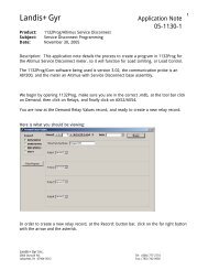
11 Hardware<br />
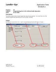
11.1 Protocol Converter Board<br />
Protocol Converter Board:<br />
Diagnostic LEDs<br />
E1<br />
E2<br />
E1<br />
E3<br />
E5<br />
<strong>DNP</strong> Program<br />
EPROM<br />
E5<br />
E2<br />
E4<br />
E3<br />
E4<br />
E6<br />
E7<br />
E7<br />
E6<br />
V25<br />
Processor<br />
E8<br />
E9<br />
E10<br />
E8<br />
E9<br />
E10<br />
11.1.1 Jumper Installations Protocol Board<br />
Host Serial Ports (connection from Protocol Board to host computer):<br />
Port Jumper Position Function<br />
E1 Not Used On Standard Board
**** E1 A Common Ground<br />
**** E1 B Isolated Ground<br />
RS-232 (J2) E2 A RX data<br />
RS-485 (J2) E2 B RX data<br />
**** E2 B Isolated RS232<br />
E3 *Not Used Ring indicate<br />
E4 A RS232 CTS used, signal from external source<br />
E4 B RS232 CTS not used & RS485<br />
E5 Don’t Care RS232<br />
RS485 E5 A RX data Recommended<br />
**** E5 B RX data Isolated RS232<br />
E6 In RS485 Terminated Not Recommended<br />
E6 Out RS485 Un-terminated Recommended<br />
E7 N/A Not customer configurable<br />
E8 N/A Not customer configurable<br />
Meter Serial Port (connection from Protocol Board to CPU of meter):<br />
Jumper Position Function<br />
E9 In TXD connected to backplane (standard)<br />
E9 Out RXD connected to RS-232 external<br />
E10 A RXD connected to backplane (standard)<br />
E10 B RXD connected to RS-232 external<br />
Example of jumper settings:<br />
Application:<br />
Configured to talk to the meter processor on the SuperBoard over the backplane (i.e., bus) on<br />
the Mother Board. The host interface is RS-232 with CTS not used.<br />
Jumpers on Protocol Converter Board:<br />
For meter serial port: E9 In; E10 on A.<br />
For host connection: E2 on A, , E4 on B, E5 on A.<br />
NOTE: You can convert from RS232 to RS485 by moving E2 from the jumper from “A” to “B”.<br />
**** Indicates position NOT USED on standard board.<br />
Jumpers on SuperBoard:
E9 in position 2-3 for operation with Protocol Converter<br />
Note: If E9 is in position 1-2, RS-232 port #2 is active for other purposes.<br />
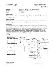
11.2 Display Board<br />
SuperBoard, Component and Solder Side:
11.2.1 Jumper Installations Display Board<br />
E9 in position 2-3 for operation with Protocol Converter
12 Device Profile Document<br />
<strong>DNP</strong> <strong>V3.00</strong><br />
DEVICE PROFILE DOCUMENT<br />
Vendor Name: Landis + Gyr Inc.<br />
Device Name: MAXsys 2510 Solid State Meter with optional Protocol Converter Board;<br />
Protocol Converter Board firmware version V016, revision R03.<br />
Highest <strong>DNP</strong> Level Supported:<br />
For Requests : 2<br />
For Responses : 2<br />
Device Function:<br />
Master ⌧ Slave<br />
Notable objects, functions, and / or qualifiers supported in addition to the Highest <strong>DNP</strong> Levels<br />
Supported (the complete list is described in the attached table):<br />
See attached<br />
Maximum Data Link Frame Size (octets):<br />
Transmitted 292<br />
Received (must be 292)<br />
Maximum Application Fragment Size (octets):<br />
Transmitted 2048 (if >2048, must<br />
be configurable<br />
Received 1024 (must be >= 249)<br />
Maximum Data Link Re-tries:<br />
None<br />
Fixed at _______________________<br />
⌧ Configurable, range: 0 or 2<br />
Maximum Application Layer Re-tries:<br />
⌧ None<br />
Configurable, range _______ to _______<br />
(Fixed is not permitted)
Requires Data Link Layer Confirmation:<br />
Never<br />
Always<br />
Sometimes If 'Sometimes', when ______________________________________________<br />
⌧ Configurable If 'Configurable', how Table32 Flag1.Bit12<br />
Requires Application Layer Confirmation:<br />
Never<br />
Always (not recommended)<br />
⌧ When reporting Event Data (Slave devices only)<br />
⌧ When sending multi-fragment responses (Slave devices only)<br />
Sometimes If 'Sometimes', when ______________________________________________<br />
Configurable If 'Configurable', how ______________________________________________<br />
Timeouts while waiting for:<br />
Data Link Confirm None ⌧ Fixed at 300 msec Variable Configurable<br />
Complete Appl. Fragment ⌧ None Fixed at _________ Variable Configurable<br />
Application Confirm None ⌧ Fixed at 3 seconds Variable Configurable<br />
Complete Appl. Response ⌧ None Fixed at _________ Variable Configurable<br />
Others The baud field in table 32 holds a 2-bit code in bits 5 and 4 of the 16-bit field for <strong>DNP</strong> transmit timeout. If the<br />
value is programmed, the <strong>DNP</strong> firmware will cause a reset after the defined period if it has not responded to <strong>DNP</strong><br />
activity. The timeout needs a first <strong>DNP</strong> activity. 0 = No timeout resets, 1 = Two minute timeout resets, 2 = One hour<br />
timeout resets and 3 = One day timeout<br />
reset.__________________________________________________________________________<br />
Attach explanation if 'Variable' or 'Configurable' was checked for any timeout<br />
Sends/Executes Control Operations:<br />
WRITE Binary Outputs ⌧ Never Always Sometimes Configurable<br />
SELECT/OPERATE Never Always Sometimes ⌧ Configurable †<br />
DIRECT OPERATE Never Always Sometimes ⌧ Configurable †<br />
DIRECT OPERATE - NO ACK Never Always Sometimes ⌧ Configurable †<br />
Count > 1 ⌧ Never Always Sometimes Configurable<br />
Pulse On Never ⌧ Always Sometimes Configurable<br />
Pulse Off ⌧ Never Always Sometimes Configurable<br />
Latch On Never ⌧ Always Sometimes Configurable<br />
Latch Off Never ⌧ Always Sometimes Configurable<br />
Trip/Close ⌧ Never Always Sometimes Configurable<br />
Raise/Lower ⌧ Never Always Sometimes Configurable<br />
Queue ⌧ Never Always Sometimes Configurable<br />
Clear Queue Never ⌧ Always Sometimes Configurable<br />
† To support control operations and conform to the Subset Definitions, either 'Always' or 'Configurable' must be selected.
WRITE Analog Outputs ⌧ Never Always Sometimes Configurable<br />
SELECT/OPERATE ⌧ Never Always Sometimes Configurable †<br />
DIRECT OPERATE ⌧ Never Always Sometimes Configurable †<br />
DIRECT OPERATE - NO ACK ⌧ Never Always Sometimes Configurable †<br />
Maximum Select/Execute Delay Time:<br />
Not Applicable<br />
⌧ Fixed at 4 seconds<br />
Configurable, range _______ to _______ seconds<br />
Attach explanation if 'Sometimes' or 'Configurable' was checked for any operation.<br />
Expects Binary Input Change Events:<br />
FILL OUT THE FOLLOWING ITEM FOR MASTER DEVICES ONLY:<br />
Either time-tagged or non-time-tagged for a single event<br />
Both time-tagged and non-time-tagged for a single event<br />
Configurable (attach explanation)<br />
FILL OUT THE FOLLOWING ITEMS FOR SLAVE DEVICES ONLY:
TimeSync Information :<br />
a.) TimeSync Period<br />
Never<br />
Fixed at _______ seconds<br />
⌧Configurable, range _1 minute_ to _255 Months (4 weeks per month)<br />
b.) Maximum time base drift over a 10 minute interval : < 1 ms<br />
c.) Maximum Internal Time Reference Error when set via <strong>DNP</strong> :<br />
2000 ms<br />
d.) Maximum Delay Measurement error : 20 ms<br />
e.) Maximum response time :<br />
1000 ms<br />
f.) Event data time-tag error - if different than (c) :<br />
Binary Input Change Events _________ ms<br />
Counter Change Events _________ ms<br />
Frozen Counter Change Events _________ ms<br />
Analog Change Events _________ ms<br />
Frozen Analog Change Events _________ ms<br />
Reports Binary Input Change Events when no<br />
specific variation requested:<br />
Never<br />
Only time-tagged<br />
Only non-time-tagged<br />
⌧ Configurable to send both, one or the other<br />
(attach explanation) Table 50 default<br />
variation configuration<br />
Sends Unsolicited Responses:<br />
⌧ Never<br />
Configurable (attach explanation)<br />
Only certain objects<br />
Sometimes (attach explanation)<br />
ENABLE/DISABLE UNSOLICITED<br />
Function codes supported<br />
Supports Collision Avoidance:<br />
Never<br />
Always<br />
⌧ Configurable (attach explanation)<br />
Reports time-tagged Binary Input Change Events when no<br />
specific variation requested:<br />
Never<br />
Binary Input Change With Time<br />
Binary Input Change With Relative Time<br />
⌧ Configurable (attach explanation) Table 50 default<br />
variation configuration<br />
Sends Static Data in Unsolicited Responses:<br />
⌧ Never<br />
When Device Restarts<br />
When Status Flags Change<br />
No other options are permitted.<br />
Collision Avoidance Detection Method:<br />
Not Applicable<br />
⌧ Link Activity<br />
DCD - with aid of external device<br />
DCD - without aid of external device
Default Counter Object/Variation:<br />
No Counters Reported<br />
⌧ Configurable (attach explanation)<br />
Default Object ______________<br />
Default Variation ______________<br />
Point-by-point list attached<br />
Counters Roll Over at:<br />
No Counters Reported<br />
Configurable (attach explanation)<br />
16 Bits<br />
32 Bits<br />
⌧ Other Value _Depends on counter size_<br />
Point-by-point list attached<br />
Source Address Filtering:<br />
⌧ Not Supported<br />
Configurable (attach explanation)<br />
Sends Multi-Fragment Responses: ⌧ Yes No
13 <strong>DNP</strong> 3.00 Implementation Table<br />
<strong>DNP</strong> 3.00 - IMPLEMENTATION TABLE<br />
OBJECT<br />
REQUEST<br />
(slave must parse)<br />
RESPONSE<br />
(master must parse)<br />
Obj Var Description Func Codes<br />
(dec)<br />
1 0 Binary Input – All Variations<br />
1 1 Binary Input<br />
1 2 Binary Input with Status<br />
1(Read)<br />
1(Read)<br />
1(Read)<br />
Qual Codes (hex) Func Codes Qual Codes<br />
(hex)<br />
00,01(Start-Stop)<br />
06(All Data)<br />
00,01(Start-Stop)<br />
06(All Data)<br />
00,01(Start-Stop)<br />
06(All Data)<br />
129 (Resp) 00 (Start-Stop)<br />
129 (Resp) 00 (Start-Stop)<br />
2 0 Binary Input Change – All Variations<br />
2 1 Binary Input Change without Time<br />
2 2 Binary Input Change with Time<br />
2 3 Binary Input Change with Relative Time<br />
10 0 Binary Output – All Variations<br />
10 1 Binary Output<br />
10 2 Binary Output Status<br />
12 0 Control Block – All Variations<br />
12 1 Control Relay Output Block<br />
12 2 Pattern Control Block<br />
12 3 Pattern Mask<br />
1(Read)<br />
20(En Unsol)<br />
21(Dis Unsol)<br />
22(Assign Cl)<br />
1(Read)<br />
20(En Unsol)<br />
21(Dis Unsol)<br />
22(Assign Cl)<br />
1(Read)<br />
20(En Unsol)<br />
21(Dis Unsol)<br />
22(Assign Cl)<br />
1(Read)<br />
20(En Unsol)<br />
21(Dis Unsol)<br />
22(Assign Cl)<br />
1(Read)<br />
None<br />
1(Read)<br />
None<br />
3(Select)<br />
4(Operate)<br />
5(Dir Operate)<br />
6(Dop/NoAck<br />
None<br />
None<br />
06(All Data)<br />
07,08(Limited Qty)<br />
06(All Data)<br />
07,08(Limited Qty)<br />
06(All Data)<br />
07,08(Limited Qty)<br />
06(All Data)<br />
07,08(Limited Qty)<br />
00,01(Start-Stop)<br />
06(All Data)<br />
00,01(Start-Stop)<br />
06(All Data)<br />
129 (Resp) 28 (Index)<br />
129 (Resp) 28 (Index)<br />
129 (Resp) 28 (Index)<br />
129 (Resp) 00 (Start-Stop)<br />
17,28 (Index) 129 (Resp) Echo of Request<br />
41
OBJECT<br />
REQUEST<br />
(slave must parse)<br />
RESPONSE<br />
(master must parse)<br />
Obj Var Description Func Codes<br />
(dec)<br />
20 0 Binary Counter - All Variations<br />
20 1 32-Bit Binary Counter<br />
20 2 16-Bit Binary Counter<br />
20 3 32-Bit Delta Counter<br />
20 4 16-Bit Delta Counter<br />
1(Read)<br />
7(Imm Freeze)<br />
8(Imm Freeze,<br />
NoAck)<br />
9(Frz & Clr)<br />
10(Frz & Clr,<br />
NoAck)<br />
11(Frz/Time)<br />
12(Frz/Time,<br />
NoAck)<br />
1(Read)<br />
7(Imm Freeze)<br />
8(Imm Freeze,<br />
NoAck)<br />
9(Frz & Clr)<br />
10(Frz & Clr,<br />
NoAck)<br />
11(Frz/Time)<br />
12(Frz/Time,<br />
NoAck)<br />
1(Read)<br />
7(Imm Freeze)<br />
8(Imm Freeze,<br />
NoAck)<br />
9(Frz & Clr)<br />
10(Frz & Clr,<br />
NoAck)<br />
11(Frz/Time)<br />
12(Frz/Time,<br />
NoAck)<br />
1(Read)<br />
7(Imm Freeze)<br />
8(Imm Freeze,<br />
NoAck)<br />
9(Frz & Clr)<br />
10(Frz & Clr,<br />
NoAck)<br />
11(Frz/Time)<br />
12(Frz/Time,<br />
NoAck)<br />
1(Read)<br />
7(Imm Freeze)<br />
8(Imm Freeze,<br />
NoAck)<br />
9(Frz & Clr)<br />
10(Frz & Clr,<br />
NoAck)<br />
11(Frz/Time)<br />
12(Frz/Time,<br />
NoAck)<br />
Qual Codes (hex) Func Codes Qual Codes<br />
(hex)<br />
00,01(Start-Stop)<br />
06(All Data)<br />
00,01(Start-Stop)<br />
06(All Data)<br />
00,01(Start-Stop)<br />
06(All Data)<br />
00,01(Start-Stop)<br />
06(All Data)<br />
00,01(Start-Stop)<br />
06(All Data)<br />
129 (Resp) 00 (Start-Stop)<br />
129 (Resp) 00 (Start-Stop)<br />
129 (Resp) 00 (Start-Stop)<br />
129 (Resp) 00 (Start-Stop)<br />
42
OBJECT<br />
REQUEST<br />
(slave must parse)<br />
RESPONSE<br />
(master must parse)<br />
Obj Var Description Func Codes<br />
(dec)<br />
20 5 32-Bit Binary Counter without Flag<br />
20 6 16-Bit Binary Counter without Flag<br />
20 7 32-Bit Delta Counter without Flag<br />
20 8 16-Bit Delta Counter without Flag<br />
1(Read)<br />
7(Imm Freeze)<br />
8(Imm Freeze,<br />
NoAck)<br />
9(Frz & Clr)<br />
10(Frz & Clr,<br />
NoAck)<br />
11(Frz/Time)<br />
12(Frz/Time,<br />
NoAck)<br />
1(Read)<br />
7(Imm Freeze)<br />
8(Imm Freeze,<br />
NoAck)<br />
9(Frz & Clr)<br />
10(Frz & Clr,<br />
NoAck)<br />
11(Frz/Time)<br />
12(Frz/Time,<br />
NoAck)<br />
1(Read)<br />
7(Imm Freeze)<br />
8(Imm Freeze,<br />
NoAck)<br />
9(Frz & Clr)<br />
10(Frz & Clr,<br />
NoAck)<br />
11(Frz/Time)<br />
12(Frz/Time,<br />
NoAck)<br />
1(Read)<br />
7(Imm Freeze)<br />
8(Imm Freeze,<br />
NoAck)<br />
9(Frz & Clr)<br />
10(Frz & Clr,<br />
NoAck)<br />
11(Frz/Time)<br />
12(Frz/Time,<br />
NoAck)<br />
Qual Codes (hex) Func Codes Qual Codes<br />
(hex)<br />
00,01(Start-Stop)<br />
06(All Data)<br />
00,01(Start-Stop)<br />
06(All Data)<br />
00,01(Start-Stop)<br />
06(All Data)<br />
00,01(Start-Stop)<br />
06(All Data)<br />
129 (Resp) 00 (Start-Stop)<br />
129 (Resp) 00 (Start-Stop)<br />
129 (Resp) 00 (Start-Stop)<br />
129 (Resp) 00 (Start-Stop)<br />
43
OBJECT<br />
REQUEST<br />
(slave must parse)<br />
RESPONSE<br />
(master must parse)<br />
Obj Var Description Func Codes<br />
(dec)<br />
21 0 Frozen Counter - All Variations<br />
21 1 32-Bit Frozen Counter<br />
1(Read)<br />
1(Read)<br />
Qual Codes (hex) Func Codes Qual Codes<br />
(hex)<br />
00,01(Start-Stop)<br />
06(All Data)<br />
00,01(Start-Stop)<br />
06(All Data)<br />
129 (Resp) 00 (Start-Stop)<br />
1(Read)<br />
00,01(Start-Stop)<br />
129 (Resp) 00 (Start-Stop)<br />
21 2 16-Bit Frozen Counter<br />
06(All Data)<br />
1(Read)<br />
00,01(Start-Stop)<br />
129 (Resp) 00 (Start-Stop)<br />
21 3 32-Bit Frozen Delta Counter<br />
06(All Data)<br />
1(Read)<br />
00,01(Start-Stop)<br />
129 (Resp) 00 (Start-Stop)<br />
21 4 16-Bit Frozen Delta Counter<br />
06(All Data)<br />
21 5<br />
32-Bit Frozen Counter with Time of<br />
Freeze<br />
1(Read)<br />
00,01(Start-Stop)<br />
06(All Data)<br />
129 (Resp) 00 (Start-Stop)<br />
21 6<br />
16-Bit Frozen Counter with Time of<br />
Freeze<br />
1(Read)<br />
00,01(Start-Stop)<br />
06(All Data)<br />
129 (Resp) 00 (Start-Stop)<br />
21 7<br />
32-Bit Frozen Delta Counter with Time of<br />
Freeze<br />
1(Read)<br />
00,01(Start-Stop)<br />
06(All Data)<br />
129 (Resp) 00 (Start-Stop)<br />
21 8<br />
16-Bit Frozen Delta Counter with Time of<br />
Freeze<br />
1(Read)<br />
00,01(Start-Stop)<br />
06(All Data)<br />
129 (Resp) 00 (Start-Stop)<br />
1(Read)<br />
00,01(Start-Stop)<br />
129 (Resp) 00 (Start-Stop)<br />
21 9 32-Bit Frozen Counter without Flag<br />
06(All Data)<br />
1(Read) 00,01(Start-Stop)<br />
21 10 16-Bit Frozen Counter without Flag<br />
06(All Data)<br />
32-Bit Frozen Delta Counter without Flag 1(Read) 00,01(Start-Stop)<br />
21 11<br />
06(All Data)<br />
16-Bit Frozen Delta Counter without Flag 1(Read) 00,01(Start-Stop)<br />
21 12<br />
06(All Data)<br />
129 (Resp) 00 (Start-Stop)<br />
129 (Resp) 00 (Start-Stop)<br />
129 (Resp) 00 (Start-Stop)<br />
44
OBJECT<br />
REQUEST<br />
(slave must parse)<br />
RESPONSE<br />
(master must parse)<br />
Obj Var Description Func Codes<br />
(dec)<br />
22 0 Counter Change Event – All Variations<br />
22 1 32-Bit Counter Change Event without<br />
Time<br />
22 2 16-Bit Counter Change Event without<br />
Time<br />
22 3 32-Bit Delta Counter Change Event<br />
without Time<br />
22 4 16-Bit Delta Counter Change Event<br />
without Time<br />
1(Read)<br />
20(En Unsol)<br />
21(Dis Unsol)<br />
22(Assign Cl)<br />
1(Read)<br />
20(En Unsol)<br />
21(Dis Unsol)<br />
22(Assign Cl)<br />
1(Read)<br />
20(En Unsol)<br />
21(Dis Unsol)<br />
22(Assign Cl)<br />
1(Read)<br />
20(En Unsol)<br />
21(Dis Unsol)<br />
22(Assign Cl)<br />
1(Read)<br />
20(En Unsol)<br />
21(Dis Unsol)<br />
22(Assign Cl)<br />
Qual Codes (hex) Func Codes Qual Codes<br />
(hex)<br />
06(All Data)<br />
07,08(Limited Qty)<br />
06(All Data)<br />
07,08(Limited Qty)<br />
06(All Data)<br />
07,08(Limited Qty)<br />
06(All Data)<br />
07,08(Limited Qty)<br />
06(All Data)<br />
07,08(Limited Qty)<br />
129 (Resp) 28 (Index)<br />
129 (Resp) 28 (Index)<br />
129 (Resp) 28 (Index)<br />
129 (Resp) 28 (Index)<br />
22 5 32-Bit Counter Change Event with Time<br />
22 6 16-Bit Counter Change Event with Time<br />
22 7 32-Bit Delta Counter Change Event with<br />
Time<br />
22 8 16-Bit Delta Counter Change Event with<br />
Time<br />
1(Read)<br />
20(En Unsol)<br />
21(Dis Unsol)<br />
22(Assign Cl)<br />
1(Read)<br />
20(En Unsol)<br />
21(Dis Unsol)<br />
22(Assign Cl)<br />
1(Read)<br />
20(En Unsol)<br />
21(Dis Unsol)<br />
22(Assign Cl)<br />
1(Read)<br />
20(En Unsol)<br />
21(Dis Unsol)<br />
22(Assign Cl)<br />
06(All Data)<br />
07,08(Limited Qty)<br />
06(All Data)<br />
07,08(Limited Qty)<br />
06(All Data)<br />
07,08(Limited Qty)<br />
06(All Data)<br />
07,08(Limited Qty)<br />
129 (Resp) 28 (Index)<br />
129 (Resp) 28 (Index)<br />
129 (Resp) 28 (Index)<br />
129 (Resp) 28 (Index)<br />
45
OBJECT<br />
REQUEST<br />
(slave must parse)<br />
RESPONSE<br />
(master must parse)<br />
Obj Var Description Func Codes<br />
(dec)<br />
23 0 Frozen Counter Event – All Variations<br />
1(Read)<br />
20(En Unsol)<br />
21(Dis Unsol)<br />
22(Assign Cl)<br />
Qual Codes (hex) Func Codes Qual Codes<br />
(hex)<br />
06(All Data)<br />
07,08(Limited Qty)<br />
1(Read)<br />
06(All Data)<br />
129 (Resp) 28 (Index)<br />
23 1 32-Bit Frozen Counter Event without Time<br />
20(En Unsol)<br />
07,08(Limited Qty)<br />
21(Dis Unsol)<br />
22(Assign Cl)<br />
1(Read)<br />
06(All Data)<br />
129 (Resp) 28 (Index)<br />
23 2 16-Bit Frozen Counter Event without Time<br />
20(En Unsol)<br />
07,08(Limited Qty)<br />
21(Dis Unsol)<br />
22(Assign Cl)<br />
1(Read)<br />
06(All Data)<br />
129 (Resp) 28 (Index)<br />
23 3 32-Bit Frozen Delta Counter Event without<br />
Time<br />
20(En Unsol)<br />
21(Dis Unsol)<br />
07,08(Limited Qty)<br />
22(Assign Cl)<br />
1(Read)<br />
06(All Data)<br />
129 (Resp) 28 (Index)<br />
23 4 16-Bit Frozen Delta Counter Event without<br />
Time<br />
20(En Unsol)<br />
21(Dis Unsol)<br />
07,08(Limited Qty)<br />
22(Assign Cl)<br />
1(Read)<br />
06(All Data)<br />
129 (Resp) 28 (Index)<br />
23 5 32-Bit Frozen Counter Event with Time<br />
20(En Unsol)<br />
07,08(Limited Qty)<br />
21(Dis Unsol)<br />
22(Assign Cl)<br />
1(Read)<br />
06(All Data)<br />
129 (Resp) 28 (Index)<br />
23 6 16-Bit Frozen Counter Event with Time<br />
20(En Unsol)<br />
07,08(Limited Qty)<br />
21(Dis Unsol)<br />
22(Assign Cl)<br />
1(Read)<br />
06(All Data)<br />
129 (Resp) 28 (Index)<br />
23 7 32-Bit Frozen Delta Counter Event with<br />
Time<br />
20(En Unsol)<br />
21(Dis Unsol)<br />
07,08(Limited Qty)<br />
22(Assign Cl)<br />
23 8 16-Bit Frozen Delta Counter Event with<br />
Time<br />
1(Read)<br />
20(En Unsol)<br />
21(Dis Unsol)<br />
06(All Data)<br />
07,08(Limited Qty)<br />
129 (Resp) 28 (Index)<br />
22(Assign Cl)<br />
46
OBJECT<br />
REQUEST<br />
(slave must parse)<br />
RESPONSE<br />
(master must parse)<br />
Obj Var Description Func Codes<br />
(dec)<br />
30 0 Analog Input – All Variations<br />
30 1 32-Bit Analog Input<br />
30 2 16-Bit Analog Input<br />
30 3 32-Bit Analog Input without Flag<br />
30<br />
4<br />
16-Bit Analog Input without Flag<br />
1(Read)<br />
7(Imm Freeze)<br />
8(Imm Freeze,<br />
NoAck)<br />
11(Frz/Time)<br />
12(Frz/Time,<br />
NoAck)<br />
1(Read)<br />
7(Imm Freeze)<br />
8(Imm Freeze,<br />
NoAck)<br />
11(Frz/Time)<br />
12(Frz/Time,<br />
NoAck)<br />
1(Read)<br />
7(Imm Freeze)<br />
8(Imm Freeze,<br />
NoAck)<br />
11(Frz/Time)<br />
12(Frz/Time,<br />
NoAck)<br />
1(Read)<br />
7(Imm Freeze)<br />
8(Imm Freeze,<br />
NoAck)<br />
11(Frz/Time)<br />
12(Frz/Time,<br />
NoAck)<br />
1(Read)<br />
7(Imm Freeze)<br />
8(Imm Freeze,<br />
NoAck)<br />
11(Frz/Time)<br />
12(Frz/Time,<br />
NoAck)<br />
Qual Codes (hex) Func Codes Qual Codes<br />
(hex)<br />
00,01(Start-Stop)<br />
06(All Data)<br />
00,01(Start-Stop)<br />
06(All Data)<br />
00,01(Start-Stop)<br />
06(All Data)<br />
00,01(Start-Stop)<br />
06(All Data)<br />
00,01(Start-Stop)<br />
06(All Data)<br />
129 (Resp) 00 (Start-Stop)<br />
129 (Resp) 00 (Start-Stop)<br />
129 (Resp) 00 (Start-Stop)<br />
129 (Resp) 00 (Start-Stop)<br />
31 0 Frozen Analog Input – All Variations<br />
1(Read)<br />
00,01(Start-Stop)<br />
06(All Data)<br />
31 1 32-Bit Frozen Analog Input<br />
1(Read)<br />
00,01(Start-Stop)<br />
06(All Data)<br />
129 (Resp) 00 (Start-Stop)<br />
31 2 16-Bit Frozen Analog Input<br />
1(Read)<br />
00,01(Start-Stop)<br />
06(All Data)<br />
129 (Resp) 00 (Start-Stop)<br />
31 3<br />
32-Bit Frozen Analog Input with Time of<br />
Freeze<br />
1(Read)<br />
00,01(Start-Stop)<br />
06(All Data)<br />
129 (Resp) 00 (Start-Stop)<br />
31 4<br />
16-Bit Frozen Analog Input with Time of<br />
Freeze<br />
1(Read)<br />
00,01(Start-Stop)<br />
06(All Data)<br />
129 (Resp) 00 (Start-Stop)<br />
31 5<br />
31 6<br />
32-Bit Frozen Analog Input without Flag 1(Read) 00,01(Start-Stop)<br />
06(All Data)<br />
16-Bit Frozen Analog Input without Flag 1(Read) 00,01(Start-Stop)<br />
06(All Data)<br />
129 (Resp) 00 (Start-Stop)<br />
129 (Resp) 00 (Start-Stop)<br />
47
OBJECT<br />
REQUEST<br />
(slave must parse)<br />
RESPONSE<br />
(master must parse)<br />
Obj Var Description Func Codes<br />
(dec)<br />
32 0<br />
Analog Change Event - All Variations<br />
32 1 32-Bit Analog Change Event without Time<br />
32 2 16-Bit Analog Change Event without Time<br />
32 3 32-Bit Analog Change Event with Time<br />
1(Read)<br />
20(En Unsol)<br />
21(Dis Unsol)<br />
22(Assign Cl)<br />
1(Read)<br />
20(En Unsol)<br />
21(Dis Unsol)<br />
22(Assign Cl)<br />
1(Read)<br />
20(En Unsol)<br />
21(Dis Unsol)<br />
22(Assign Cl)<br />
1(Read)<br />
20(En Unsol)<br />
21(Dis Unsol)<br />
22(Assign Cl)<br />
Qual Codes (hex) Func Codes Qual Codes<br />
(hex)<br />
06(All Data)<br />
07,08(Limited Qty)<br />
06(All Data)<br />
07,08(Limited Qty)<br />
06(All Data)<br />
07,08(Limited Qty)<br />
06(All Data)<br />
07,08(Limited Qty)<br />
129 (Resp) 28 (Index)<br />
129 (Resp) 28 (Index)<br />
129 (Resp) 28 (Index)<br />
1(Read)<br />
06(All Data)<br />
129 (Resp) 28 (Index)<br />
32 4 16-Bit Analog Change Event with Time<br />
20(En Unsol)<br />
07,08(Limited Qty)<br />
21(Dis Unsol)<br />
22(Assign Cl)<br />
1(Read)<br />
06(All Data)<br />
33 0 Frozen Analog Event - All Variations<br />
20(En Unsol)<br />
07,08(Limited Qty)<br />
21(Dis Unsol)<br />
22(Assign Cl)<br />
1(Read)<br />
06(All Data)<br />
129 (Resp) 28 (Index)<br />
33 1 32-Bit Frozen Analog Event without Time<br />
20(En Unsol)<br />
07,08(Limited Qty)<br />
21(Dis Unsol)<br />
22(Assign Cl)<br />
1(Read)<br />
06(All Data)<br />
129 (Resp) 28 (Index)<br />
33 2 16-Bit Frozen Analog Event without Time<br />
20(En Unsol)<br />
07,08(Limited Qty)<br />
21(Dis Unsol)<br />
22(Assign Cl)<br />
1(Read)<br />
06(All Data)<br />
129 (Resp) 28 (Index)<br />
33 3 32-Bit Frozen Analog Event with Time<br />
20(En Unsol)<br />
07,08(Limited Qty)<br />
21(Dis Unsol)<br />
22(Assign Cl)<br />
33 4 16-Bit Frozen Analog Event with Time<br />
1(Read)<br />
20(En Unsol)<br />
21(Dis Unsol)<br />
22(Assign Cl)<br />
06(All Data)<br />
07,08(Limited Qty)<br />
129 (Resp) 28 (Index)<br />
48
OBJECT<br />
REQUEST<br />
(slave must parse)<br />
RESPONSE<br />
(master must parse)<br />
Obj Var Description Func Codes<br />
(dec)<br />
40 0 Analog Output Status - All Variations<br />
40 1 32-Bit Analog Output Status<br />
None<br />
None<br />
Qual Codes (hex) Func Codes Qual Codes<br />
(hex)<br />
40 2 16-Bit Analog Output Status<br />
41 0 Analog Output Block - All Variations<br />
41 1 32-Bit Analog Output Block<br />
41 2 16-Bit Analog Output Block<br />
50 0 Time and Date - All Variations<br />
50 1 Time and Date<br />
50 2 Time and Date with Interval<br />
51 0 Time and Date CTO - All Variations<br />
51 1 Time and Date CTO<br />
51 2 Unsynchronized Time and Date CTO<br />
52 0 Time Delay - All Variations<br />
52 1 Time Delay Coarse<br />
52 2 Time Delay Fine<br />
60 0<br />
60 1 Class 0 Data<br />
None<br />
None<br />
None<br />
None<br />
1(Read) 07,08 (Qty = 1)<br />
1(Read) 07,08 (Qty = 1) 129 (Resp) 07 (Qty = 1)<br />
2(Write)<br />
11(Frz/Time) 07,08 (Qty = 1) 129 (Resp) 07 (Qty = 1)<br />
12(Frz/Time,<br />
NoAck)<br />
None<br />
None Part of Obj 2 07 (Qty = 1)<br />
Var 3 Resp.<br />
None<br />
None<br />
None<br />
None<br />
1(Read) 06(All Data) 129 (Resp) 00 (Start-Stop)<br />
60 2 Class 1 Data<br />
1(Read)<br />
20(En Unsol)<br />
21(Dis Unsol)<br />
22(Assign Cl)<br />
1(Read)<br />
06(All Data)<br />
07,08(Limited Qty)<br />
06(All Data)<br />
129 (Resp) 28 (Index)<br />
129 (Resp) 28 (Index)<br />
60 3 Class 2 Data<br />
20(En Unsol)<br />
07,08(Limited Qty)<br />
21(Dis Unsol)<br />
22(Assign Cl)<br />
1(Read)<br />
06(All Data)<br />
129 (Resp) 28 (Index)<br />
60 4 Class 3 Data<br />
20(En Unsol)<br />
07,08(Limited Qty)<br />
21(Dis Unsol)<br />
22(Assign Cl)<br />
49
OBJECT<br />
REQUEST<br />
(slave must parse)<br />
RESPONSE<br />
(master must parse)<br />
Obj Var Description Func Codes<br />
(dec)<br />
70 1 File Identifier<br />
80 1 Internal Indications<br />
None<br />
Qual Codes (hex) Func Codes Qual Codes<br />
(hex)<br />
2(Write) 00,01(Start-Stop) 129 (Resp) Null<br />
None<br />
81 1 Storage Object<br />
82 1 Device Profile<br />
83 1 Private Registration Object<br />
83 2 Private Registration Object Descriptor<br />
90 1 Application Identifier<br />
100 1 Short Floating Point<br />
100 2 Long Floating Point<br />
100 3 Extended Floating Point<br />
101 1 Small Packed Binary-Coded Decimal<br />
101 2 Medium Packed Binary-Coded Decimal<br />
101 3 Large Packed Binary-Coded Decimal<br />
No Object (Cold Restart)<br />
No Object (Warm Restart)<br />
No Object (Delay Measurement)<br />
None<br />
None<br />
None<br />
None<br />
None<br />
None<br />
None<br />
None<br />
None<br />
None<br />
13(Cold-<br />
Restart)<br />
14(Warm-<br />
Restart)<br />
None<br />
129 (Resp) Null<br />
129 (Resp) Null<br />
50