Ic Ib Ia Va Vb Vc - Landis+Gyr
Ic Ib Ia Va Vb Vc - Landis+Gyr
Ic Ib Ia Va Vb Vc - Landis+Gyr
- No tags were found...

Create successful ePaper yourself
Turn your PDF publications into a flip-book with our unique Google optimized e-Paper software.
<strong>Landis+Gyr</strong><br />
Application Note<br />
05-0320-1<br />
Product:<br />
MAXsys meters and other Transformer Rated Meters<br />
Subject:<br />
Information on the wiring of Instrument Transformers<br />
Date: 03/20/2005<br />
Background Information<br />
Warning this is to be used for information only. This is not a<br />
recommendation or instructions on how to wire Instrument<br />
Transformers or Meters. Only trained Meter Technicians with a<br />
good understanding of Instrument Transformer Rated meters<br />
should ever work on metering circuits and then they must always<br />
follow their company’s safe work practices. Mistakes in wiring<br />
Instruments Transformers can cause damage to equipment and<br />
death to personnel.<br />
To understand applications using instrument transformers it is important<br />
(necessary) to understand the polarity markings on the transformer as well<br />
as following your company’s safety guide lines when wiring instrument<br />
transformer rated power instrumentation. You may have heard the term,<br />
with current in on polarity, you will get current out on polarity (they were<br />
saying the signals would be the same). To help understand the polarity<br />
markings when looking at instrument transformers, you will find on the<br />
high side (primary) and on the low side (secondary) of the transformer a<br />
polarity mark. The best way to think about this, is the polarity marks are<br />
two points on the same wire, from the stand point the signal going in on<br />
polarity will be the same signal you see coming out on polarity from a<br />
phase relation, the signals will be in phase with each other (look the<br />
same), only the magnitude of the signal will change. If you think about just<br />
one VT and CT it maybe easer to see what happens. With the polarity<br />
terminal of the VT (high side) connect to the Line and the polarity terminal<br />
on the CT (high side) facing the source and the polarity terminals on the<br />
low side of the transformers connected to the “Vin” and “Iin” of the meter<br />
and with power flowing from the source to the load the meter will register<br />
in the delivered direction (you could say the voltage and current are in the<br />
same phase (direction). When the power starts flowing from the load to<br />
<strong>Landis+Gyr</strong> Inc.<br />
2800 Duncan Rd. Tel: (800) 777-2774<br />
Lafayette, IN 47904-5012 Fax: (765) 742-0936
<strong>Landis+Gyr</strong><br />
Application Note<br />
05-0320-1<br />
the source, the voltage signals remain the same however, now the current<br />
is flowing into the non-polarity side of the transformer and now the current<br />
signal has now moved by 180 degrees and the meter starts registering in<br />
the received direction.<br />
With this basic understanding we can look at three possible ways to install<br />
Instrument Transformers and connect them to a three element meter.<br />
Please remember there are many ways to connect transformers to a meter<br />
and get the same results. We are only going to look at three installations.<br />
The first one is a 4 wire wye and the last two will be on 3 wire Delta. This<br />
to help you understand the connections, it is NOT intended to be used as a<br />
meter wiring diagram. Warning because each company has its own<br />
grounding practices for instrument transformers, no grounds are shown in<br />
any of the illustrations.<br />
<strong>Landis+Gyr</strong> Inc.<br />
2800 Duncan Rd. Tel: (800) 777-2774<br />
Lafayette, IN 47904-5012 Fax: (765) 742-0936
<strong>Landis+Gyr</strong><br />
Application Note<br />
05-0320-1<br />
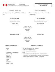
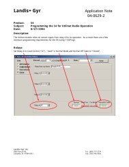
Illustration 1 represents a full 3 element meter. This will be used as a<br />
reference in illustrations 2-4.<br />
Illustration 1<br />
<strong>Va</strong> <strong>Vb</strong> <strong>Vc</strong> <strong>Ia</strong> <strong>Ib</strong> <strong>Ic</strong> <strong>Ic</strong> <strong>Ib</strong> <strong>Ia</strong> <strong>Vc</strong> <strong>Vb</strong> <strong>Vc</strong><br />
In In In In In In Out Out Out Out Out Out<br />
<strong>Va</strong> <strong>Vb</strong> <strong>Vc</strong> <strong>Ia</strong> <strong>Ib</strong> <strong>Ic</strong> <strong>Ic</strong> <strong>Ib</strong> <strong>Ia</strong> <strong>Va</strong> <strong>Vb</strong> <strong>Vc</strong><br />
In In Out Return Out Return<br />
<strong>Landis+Gyr</strong> Inc.<br />
2800 Duncan Rd. Tel: (800) 777-2774<br />
Lafayette, IN 47904-5012 Fax: (765) 742-0936
<strong>Landis+Gyr</strong><br />
Application Note<br />
05-0320-1<br />
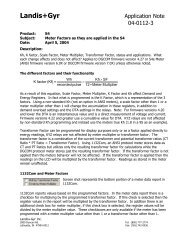
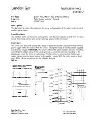
Illustration 2 represents a 4 wire Wye installation.<br />
With the connections below the delivered registers will increase when<br />
power flows from the source to the load. Note: with the VT’s being<br />
installed on the source side of CT’s, they will not be seen as load to the<br />
metering system.<br />
Illustration 2<br />
SOURCE<br />
N A B C<br />
V<br />
T<br />
To (<strong>Va</strong> in) meter<br />
To (<strong>Va</strong> out) meter or return<br />
V<br />
T<br />
V<br />
T<br />
To (<strong>Vb</strong> in) meter<br />
To (<strong>Vb</strong> out) meter or return<br />
To (<strong>Vc</strong> in) meter<br />
To (<strong>Vc</strong> out) meter or return<br />
C<br />
T<br />
To (<strong>Ia</strong> in) meter<br />
To (<strong>Ia</strong> out) meter or return<br />
C<br />
T<br />
To (<strong>Ib</strong> in) meter<br />
To (<strong>Ib</strong> out) meter or return<br />
C<br />
T<br />
To (<strong>Ic</strong> in) meter<br />
To (<strong>Ic</strong> out) meter or return<br />
LOAD<br />
<strong>Landis+Gyr</strong> Inc.<br />
2800 Duncan Rd. Tel: (800) 777-2774<br />
Lafayette, IN 47904-5012 Fax: (765) 742-0936
<strong>Landis+Gyr</strong><br />
Application Note<br />
05-0320-1<br />
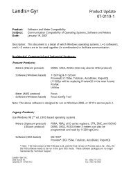
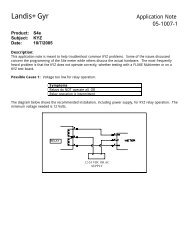
Illustration 3 represents 3 wire Delta installation. We use the same<br />
polarities in this example as we did in illustration 2. When using a three<br />
element meter like the MAXsys meter you would only use the “A & C”<br />
elements. With the MAXsys meter you would leave “B” currents open and<br />
connect “<strong>Vb</strong> in” to return (you can also leave the voltage connect open.<br />
Illustration 3<br />
SOURCE<br />
A B C<br />
V<br />
T<br />
To (<strong>Va</strong> in) meter<br />
To (<strong>Va</strong> out) meter or return<br />
V<br />
T<br />
To (<strong>Vc</strong> in) meter<br />
To (<strong>Vc</strong> out) meter or return<br />
C<br />
T<br />
To (<strong>Ia</strong> in) meter<br />
To (<strong>Ia</strong> out) meter or return<br />
C<br />
T<br />
To (<strong>Ic</strong> in) meter<br />
To (<strong>Ic</strong> out) meter or return<br />
LOAD<br />
<strong>Landis+Gyr</strong> Inc.<br />
2800 Duncan Rd. Tel: (800) 777-2774<br />
Lafayette, IN 47904-5012 Fax: (765) 742-0936
<strong>Landis+Gyr</strong><br />
Application Note<br />
05-0320-1<br />
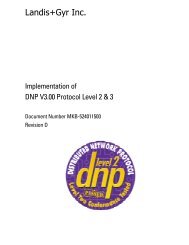
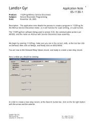
Illustration 4 represents 3 wire Delta installation. We use the same<br />
polarities in this example as we did in illustration 3, EXCEPT the polarities<br />
on the “C” phase VT has been reversed, by reversing both the primary and<br />
secondary connections we end up with the same signals. When using a<br />
three element meter like the MAXsys meter you would only use the “A & C”<br />
elements. With the MAXsys meter you would leave “B” currents open and<br />
connect “<strong>Vb</strong> in” to return (you can also leave the voltage connect open).<br />
Illustration 4<br />
SOURCE<br />
A B C<br />
V<br />
T<br />
To (<strong>Va</strong> in) meter<br />
To (<strong>Va</strong> out) meter or return<br />
V<br />
T<br />
To (<strong>Vc</strong> out) meter or return<br />
To (<strong>Vc</strong> in) meter<br />
C<br />
T<br />
To (<strong>Ia</strong> in) meter<br />
To (<strong>Ia</strong> out) meter or return<br />
C<br />
T<br />
To (<strong>Ic</strong> in) meter<br />
To (<strong>Ic</strong> out) meter or return<br />
LOAD<br />
<strong>Landis+Gyr</strong> Inc.<br />
2800 Duncan Rd. Tel: (800) 777-2774<br />
Lafayette, IN 47904-5012 Fax: (765) 742-0936