

bow-tie wide-band monopole antenna with the novel impedance
bow-tie wide-band monopole antenna with the novel impedance
bow-tie wide-band monopole antenna with the novel impedance

Create successful ePaper yourself
Turn your PDF publications into a flip-book with our unique Google optimized e-Paper software.
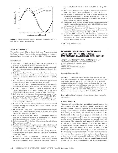
Figure 5 First experimental curves in <strong>the</strong> case of a 10.4-mm-thick PVC<br />
slab at F 8.5 GHz in transmission<br />
REFERENCES<br />
1. M.N. Afsar, J.R. Birch, and R.N. Clarke, The measurement of <strong>the</strong><br />
proper<strong>tie</strong>s of materials. Proc IEEE 74 (1986), 183–199.<br />
2. J. Musil and F. Zacek, Microwave measurements of complex permittivity<br />
by free-space methods and <strong>the</strong>ir applications. Elsevier, New<br />
York, 1986.<br />
3. D.K. Ghodgaonkar, V.V. Varadan, and V.K. Varadan, Free-space<br />
method for measurement of dielectric constants and loss tangents at<br />
microwave frequencies. IEEE Trans Instrum Meas IM-37 (1989),<br />
789–793.<br />
4. R.C. Jain, A survey of industrial scientific and medical applications of<br />
microwave energy, IETE Tech Rev 15 (1998), 443–459.<br />
5. T. Hauschild and F. Menke, Moisture measurement in masonry walls<br />
using non-invasive reflectometer. Electron Lett 34 (1998), 2413–2414.<br />
6. K. Sato, T. Manabe, J. Polivka, T. Ihara, Y. Kasashima, and K.<br />
Yamaki, Measurement of <strong>the</strong> complex refractive index of concrete at<br />
57.5 GHz. IEEE Trans. Antennas Propagat AP-44 (1996), 35–40.<br />
7. H.C. Rhim and O. Büyüköztürk, Electromagnetic proper<strong>tie</strong>s of concrete<br />
at microwave frequency range. ACI Mater J (1998), 262–271.<br />
8. K.J. Bois, A. Benally, P.S. Nowak, and R. Zoughi, Microwave nondestructive<br />
determination of sand-to-cement ratio in mortar. Res Nondestr<br />
Eval 9 (1997), 227–238.<br />
9. J. Curtis and R. Narayanan, Effects of laboratory procedures on soil<br />
electrical property measurements. IEEE Trans Instrum Meas 47<br />
(1998), 1474–1480.<br />
10. J.H. Tarng, W.R. Chang, and B.J. Hsu, Three-dimensional modeling of<br />
900-MHz and 2.44-GHz radio propagation in corridors. IEEE Trans<br />
Veh Technol VT-46 (1997), 519–527.<br />
11. K.R. Rizk, J.F. Wagen, and F. Gardiol, Two-dimensional ray-tracing<br />
modeling for propagation prediction in microcellular environments,<br />
IEEE Trans Veh Technol VT-46 (1997), 508–517.<br />
12. R.M.A. Azzam and N.M. Bashara, Ellipsometry and polarized light,<br />
Elsevier, Amsterdam, 1999.<br />
13. J. Lekner, Determination of complex refractive index and thickness of<br />
a homogeneous layer by combined reflection and transmission ellipsometry,<br />
J Opt Soc Am A 11 (1994), 2156–2158.<br />
14. G. Bader, P.V. Ashrit, F.E. Girouard, and V.V. Truong, Reflectiontransmission<br />
photoellipsometry: Theory and experiments, Appl Opt 34<br />
(1995), 1684–1691.<br />
15. K. Sato, H. Kozima, H. Masazawa, T. Manabe, T. Ihara, Y.<br />
Kasashima, and K. Yamaki, Measurements of reflection characteristics<br />
and refractive indices of interior construction materials in millimeterwave<br />
<strong>band</strong>s, IEEE 45th Veh. Technol. Conf., 1995 Vol. 1, pp. 449–<br />
453.<br />
16. A.H. Sihvola, Self-consistency aspects of dielectric mixing <strong>the</strong>ories,<br />
IEEE Trans Geosci Remote Sensing GRS-27 (1989), 710–717.<br />
17. J.P. Pugliese, A. Hammoudeh, and M.O. Al-Nuaimi, Reflection and<br />
transmission characteristics of building materials at 62 GHz, IEE<br />
Colloquium on Radio Communication at Microwave and Millimeter<br />
Wave Frequencies, 1996, pp. 6/1–6/6.<br />
18. I. Cuinas and M.G. Sanchez, Building material characterization from<br />
complex transmittivity measurements at 5.8 GHz, IEEE Trans Antennas<br />
Propagat AP-48 (2000), 1269–1271.<br />
19. O. Landron, M.J. Feuerstein, and T.S. Rappaport, In situ microwave<br />
reflection coefficient measurements for smooth and rough exterior wall<br />
surfaces, 43th Conf. Veh. Technol., 1993, pp. 77–80.<br />
20. O. Landron, M.J. Feuerstein, and T.S. Rappaport, A comparison of<br />
<strong>the</strong>oretical and empirical reflection coefficients for typical exterior<br />
wall surfaces in a mobile radio environment, IEEE Trans. Antennas<br />
Propagat AP-44 (1996), 341–351.<br />
© 2002 Wiley Periodicals, Inc.<br />
ACKNOWLEDGMENTS<br />
The authors would like to thank Christophe Vignat, Assistant<br />
Professor in Signal Processing, for his contribution to <strong>the</strong> development<br />
of data processing and to <strong>the</strong> writing of this manuscript.<br />
BOW-TIE WIDE-BAND MONOPOLE<br />
ANTENNA WITH THE NOVEL<br />
IMPEDANCE-MATCHING TECHNIQUE<br />
Jong-Pil Lee, 1 Seong-Ook Park, 1 and Sang-Keun Lee 2<br />
1 Department of Electronics Engineering Information<br />
and Communications University (ICU)<br />
Taejon, Korea<br />
2 ShinA Info. & Telecomm. Co., Ltd.<br />
Incheon, Korea<br />
Received 12 December 2001<br />
ABSTRACT: A staircase <strong>bow</strong>-<strong>tie</strong> <strong>monopole</strong>-type <strong>antenna</strong> that features<br />
a <strong>novel</strong> broad<strong>band</strong> technique is investigated experimentally and<br />
numerically. A <strong>band</strong>width of 77.1% (VSWR 2) can be achieved,<br />
and an omnidirectional radiation pattern is obtained. The electrical<br />
characteristics of <strong>the</strong> proposed <strong>antenna</strong> make it attractive for use in<br />
multi<strong>band</strong> mobile systems.© 2002 Wiley Periodicals, Inc. Microwave<br />
Opt Technol Lett 33: 448– 452, 2002; Published online in Wiley Inter-<br />
Science (www.interscience.wiley.com). DOI 10.1002/mop.10347<br />
Key words: <strong>wide</strong><strong>band</strong> <strong>monopole</strong>; wireless <strong>antenna</strong>; planar <strong>monopole</strong>;<br />
slit <strong>monopole</strong><br />
1. INTRODUCTION<br />
The design of personal handsets for mobile communication service<br />
has achieved goals such as miniaturization, light weight, and<br />
multiple function. One of <strong>the</strong> important factors of <strong>the</strong> handset is <strong>the</strong><br />
quality of communication, which is determined by numerous factors.<br />
Among <strong>the</strong>se factors, <strong>the</strong> <strong>antenna</strong> that is installed in <strong>the</strong><br />
handset and in <strong>the</strong> base station plays an important part in <strong>the</strong><br />
quality of communication. Newer mobile communication systems<br />
require a small, low-priced <strong>antenna</strong> that has multiple-<strong>band</strong>width<br />
performance. The microstrip patch <strong>antenna</strong> is <strong>wide</strong>ly employed<br />
because of its planar shape. However, it is a type of resonance<br />
<strong>antenna</strong>, and its frequency <strong>band</strong>width is a narrow <strong>band</strong> of 5%. And<br />
<strong>the</strong> patch size of <strong>the</strong> <strong>antenna</strong> is at least /2, where is <strong>the</strong><br />
wavelength of <strong>the</strong> desired frequency. So it has weaknesses at<br />
low-frequency <strong>band</strong>s (cellular and GSM <strong>band</strong>s) in an <strong>antenna</strong> size.<br />
To overcome <strong>the</strong>se weaknesses, <strong>the</strong>re are <strong>the</strong> methods of applying<br />
a short pin to a patch <strong>antenna</strong> [1] and usage of high-dielectric<br />
materials. Here a <strong>monopole</strong>-type <strong>antenna</strong> <strong>with</strong> /4 <strong>antenna</strong> size is<br />
considered. The conventional <strong>monopole</strong> and helical structures are<br />
448 MICROWAVE AND OPTICAL TECHNOLOGY LETTERS / Vol. 33, No. 6, June 20 2002
Figure 1<br />
Geometry of a <strong>bow</strong>-<strong>tie</strong>-shaped <strong>antenna</strong><br />
<strong>wide</strong>ly used in mobile handset <strong>antenna</strong>s. The modified type of<br />
<strong>antenna</strong>, which combines <strong>the</strong> two types, is used for dual-<strong>band</strong><br />
operation [2]. But <strong>the</strong> modern handset <strong>antenna</strong>s require covert,<br />
low-profile applications. This Letter proposes a <strong>novel</strong> <strong>bow</strong>-<strong>tie</strong>shaped<br />
and printed-type <strong>monopole</strong> <strong>antenna</strong> to which <strong>the</strong> new<br />
method of <strong>impedance</strong> matching is applied. This method suggests a<br />
slit at <strong>the</strong> feeding region and an extended ground plane of <strong>the</strong><br />
bottom side of <strong>antenna</strong>. The proposed <strong>antenna</strong> has a broad<strong>band</strong><br />
performance.<br />
2. DESIGN OF ANTENNA<br />
A. Monopole Antenna<br />
The <strong>monopole</strong>-type <strong>antenna</strong> has a /4 length physically and a<br />
narrow <strong>impedance</strong> <strong>band</strong>width typically. Recently various structures<br />
have been proposed to overcome <strong>the</strong> narrow-<strong>band</strong>width<br />
demerits of a <strong>monopole</strong>.<br />
First, to reduce <strong>antenna</strong> size, many researchers proposed <strong>the</strong><br />
meander line [3]. The meander line is a method by which a length<br />
of <strong>antenna</strong> is extended electrically; <strong>the</strong>refore <strong>the</strong> resonance frequency<br />
of <strong>the</strong> <strong>antenna</strong> can be efficiently shrunk. But this method<br />
also has a narrow <strong>impedance</strong> <strong>band</strong>width, like a <strong>monopole</strong>. The<br />
second proposal is to overcome <strong>the</strong> narrow <strong>band</strong>width, which is<br />
one of <strong>the</strong> demerits of <strong>the</strong> conventional <strong>monopole</strong>. Parasitic elements<br />
around <strong>the</strong> <strong>monopole</strong> <strong>antenna</strong> bring about various characteristics<br />
[4,5] such as dual <strong>band</strong> or a multi<strong>band</strong> operation. But this<br />
idea increases <strong>the</strong> size of <strong>the</strong> <strong>antenna</strong>.<br />
Figure 3 Staircase <strong>bow</strong>-<strong>tie</strong> <strong>antenna</strong> and <strong>with</strong> <strong>the</strong> new <strong>impedance</strong> matching<br />
technique applied<br />
B. Modified Monopole to Achieve Broad<strong>band</strong> Performance<br />
Rectangular- or elliptical-shaped <strong>monopole</strong>s were proposed to<br />
overcome <strong>the</strong> conventional <strong>monopole</strong> is narrow <strong>band</strong>width performance<br />
[6,7]. These structures could achieve obtain broad<strong>band</strong><br />
applications, but were difficult to apply to mobile communication<br />
handsets. Broad<strong>band</strong> performance can be obtained by using <strong>bow</strong><strong>tie</strong>-shaped<br />
<strong>monopole</strong>s [8]. The <strong>bow</strong>-<strong>tie</strong> shape has two triangles<br />
facing each o<strong>the</strong>r. In this Letter this <strong>bow</strong>-<strong>tie</strong> structure is modified<br />
to apply to a handset. One of <strong>the</strong> two opposite-sided triangles is<br />
cut, and <strong>the</strong> edge of <strong>the</strong> remaining one is fed by coplanar<br />
waveguide (CPW) (in Figure 1). The remaining triangle is transformed<br />
into <strong>the</strong> shape of a staircase <strong>bow</strong>-<strong>tie</strong> in order to apply <strong>the</strong><br />
new method of <strong>impedance</strong> matching to <strong>the</strong> above-mentioned structure,<br />
and <strong>the</strong> <strong>antenna</strong> is fabricated by using <strong>the</strong> printed circuit<br />
board (PCB) (in Figure 3).<br />
First of all, <strong>the</strong> first mentioned model, a <strong>bow</strong>-<strong>tie</strong>-shaped <strong>antenna</strong>,<br />
is shown in Figure 1. This structure is simulated by Ansoft<br />
Figure 2<br />
Simulated VSWR of a <strong>bow</strong>-<strong>tie</strong>-shaped <strong>antenna</strong><br />
Figure 4 Simulated results of <strong>the</strong> proposed model (see Figure 3) [Color<br />
figure can be viewed in <strong>the</strong> online issue, which is available at www.<br />
interscience.wiley.com.]<br />
MICROWAVE AND OPTICAL TECHNOLOGY LETTERS / Vol. 33, No. 6, June 20 2002 449
Figure 5 Photograph of <strong>the</strong> proposed <strong>antenna</strong>. (a) Top view, (b) bottom view [Color figure can be viewed in <strong>the</strong> online issue, which is available at<br />
www.interscience.wiley.com.]<br />
HFSS (version 6.0). The result is shown in Figure 2. The simulated<br />
result has 31.4% <strong>impedance</strong> <strong>band</strong>width <strong>with</strong> <strong>the</strong> frequency range<br />
0.93–1.31 GHz (VSWR 2), and <strong>the</strong> center frequency of <strong>the</strong><br />
return loss is frequency 1.21 GHz. The <strong>impedance</strong> <strong>band</strong>width of<br />
<strong>the</strong> <strong>bow</strong>-<strong>tie</strong>-shaped <strong>antenna</strong> has more <strong>wide</strong><strong>band</strong> characteristics<br />
than <strong>the</strong> conventional <strong>monopole</strong> <strong>antenna</strong>.<br />
C. Application of <strong>the</strong> New Method for<br />
Wide<strong>band</strong> Impedance Matching<br />
The new method of <strong>impedance</strong> matching is applied to a staircase<br />
<strong>bow</strong>-<strong>tie</strong>-shaped <strong>monopole</strong> to get broad<strong>band</strong> width. As shown in<br />
Figure 3, <strong>the</strong> new method of <strong>impedance</strong> matching is that CPW<br />
feeding <strong>with</strong> a ground plane is extended to <strong>the</strong> same width as <strong>the</strong><br />
<strong>antenna</strong> at <strong>the</strong> o<strong>the</strong>r side of <strong>the</strong> <strong>antenna</strong>, and a slit is made at <strong>the</strong><br />
<strong>antenna</strong>.<br />
The extended ground plane reinforces capacitance. The reinforced<br />
capacitance that results from <strong>the</strong> extended ground plane<br />
canceled <strong>the</strong> inductance of an <strong>antenna</strong> and <strong>the</strong> extra capacitance of<br />
<strong>the</strong> extended ground plane is canceled by making a slit in <strong>the</strong><br />
<strong>antenna</strong>.<br />
The results in Figure 4 are simulated, obtained by varying <strong>the</strong><br />
length (hg) of <strong>the</strong> extended ground plane and <strong>the</strong> depth (hs) of slit.<br />
The center frequency is 1.15 GHz, and <strong>the</strong> <strong>band</strong>width for<br />
VSWR 2 is 43.4%, <strong>with</strong> a frequency range of 0.96–1.4 GHz at<br />
hs 0 mm, hg 0 mm. When <strong>the</strong> length (hg) of <strong>the</strong> extended<br />
ground plane is 5 mm and <strong>the</strong> depth (hs) of <strong>the</strong> slit is 12 mm, <strong>the</strong><br />
center frequency is 1.7 GHz, and <strong>the</strong> input <strong>impedance</strong> <strong>band</strong>width<br />
for VSWR 2 is 63.1% <strong>with</strong> 1.16–2.23 GHz. Note that <strong>the</strong><br />
resonant frequencies and <strong>band</strong>width are determined by <strong>the</strong> values<br />
of hg and hs. By adjusting <strong>the</strong>se parameters carefully, it is easy to<br />
optimize <strong>the</strong> desired frequency <strong>band</strong>. This case (hg 5 mm, hs <br />
Figure 6 Measured input <strong>impedance</strong> before application of new <strong>impedance</strong><br />
matching technique [Color figure can be viewed in <strong>the</strong> online issue,<br />
which is available at www.interscience.wiley.com.]<br />
Figure 7 Measured input <strong>impedance</strong> after application of new <strong>impedance</strong><br />
matching technique [Color figure can be viewed in <strong>the</strong> online issue, which<br />
is available at www.interscience.wiley.com.]<br />
450 MICROWAVE AND OPTICAL TECHNOLOGY LETTERS / Vol. 33, No. 6, June 20 2002
12 mm) is an optimum size to achieve for <strong>the</strong> maximum frequency<br />
<strong>band</strong>width. Therefore <strong>the</strong> effect of <strong>the</strong> proposed <strong>impedance</strong>-matching<br />
method to obtain broad <strong>band</strong>width is remarkable.<br />
Figure 8 Comparison between <strong>the</strong> before case and <strong>the</strong> after case [Color<br />
figure can be viewed in <strong>the</strong> online issue, which is available at www.<br />
interscience.wiley.com.]<br />
3. FABRICATION AND MEASUREMENT<br />
Figure 5 shows <strong>the</strong> proposed <strong>antenna</strong>. The substrate used is FR-4,<br />
which is commonly used in printed circuits and is much cheaper<br />
than microwave substrates such as Duroid. The proposed <strong>antenna</strong><br />
is fabricated on an FR-4 substrate ( r 4.6). The substrate<br />
thickness is 1.6 mm. Numerous vias connecting <strong>the</strong> front and back<br />
ground planes are used in <strong>the</strong> proposed <strong>monopole</strong> (shown in Figure<br />
5) to suppress spurious parallel plate modes that are known to<br />
occur in <strong>the</strong> grounded coplanar waveguide.<br />
The VSWR, radiation pattern, and <strong>antenna</strong> gain were measured.<br />
An HP8722D network analyzer and an HP8510C <strong>antenna</strong> measurement<br />
system are used. The Smith chart shown in Figure 6 plots<br />
<strong>the</strong> measured input <strong>impedance</strong> when <strong>the</strong> <strong>novel</strong> <strong>impedance</strong> matching<br />
technique is not applied. Figure 7 shows <strong>the</strong> measured input<br />
<strong>impedance</strong> after application of <strong>the</strong> new method of <strong>impedance</strong><br />
matching. The measured VSWR of two cases (before and after<br />
application) are depicted in Figure 8. The proposed method has<br />
increased <strong>the</strong> <strong>impedance</strong> <strong>band</strong>width from 32.4% (before applica-<br />
Figure 9 Radiation patterns at 1.2 GHz (dotted line, simulated; solid line, measured). (a) xy plane ( 90°), (b) yz plane ( 90°) [Color figure can<br />
be viewed in <strong>the</strong> online issue, which is available at www.interscience.wiley.com.]<br />
Figure 10 Radiation patterns at 1.7 GHz (dotted line, simulated; solid line, measured). (a) xy plane ( 90°), (b) yz plane ( 90°) [Color figure can<br />
be viewed in <strong>the</strong> online issue, which is available at www.interscience.wiley.com.]<br />
MICROWAVE AND OPTICAL TECHNOLOGY LETTERS / Vol. 33, No. 6, June 20 2002 451
tion, 1.02–1.415 GHz) up to 77.1% (after application, 1.03–2.31<br />
GHz).<br />
Figures 9(a) and 9(b) show <strong>the</strong> radiation patterns at frequencies<br />
of 1.2 GHz of both <strong>the</strong> measured and simulated results in <strong>the</strong> xy<br />
and yz planes, respectively. The simulated and measured <strong>antenna</strong><br />
gains in <strong>the</strong> xy plane have a maximum peak at 1.9 and 1.2 dBi,<br />
respectively. Figures 10(a) and 10(b) illustrate <strong>the</strong> radiation patterns<br />
at frequencies of 1.7 GHz of both <strong>the</strong> measured and simulated<br />
results in <strong>the</strong> xy and yz planes, respectively. The simulated and<br />
measured <strong>antenna</strong> gains in <strong>the</strong> xy plane have a maximum peak at<br />
2.3 and 1.7 dBi, respectively. This slight discrepancy can be<br />
attributed to <strong>the</strong> effects of <strong>the</strong> conductor loss and dielectric loss.<br />
Note that <strong>the</strong> radiation patterns of <strong>the</strong> two frequencies (1.2 GHz,<br />
1.7 GHz) have an approximately omnidirectional pattern, similar<br />
to those of a <strong>monopole</strong>.<br />
4. CONCLUSIONS<br />
It has been demonstrated that a broad<strong>band</strong> <strong>bow</strong>-<strong>tie</strong> <strong>monopole</strong> type<br />
<strong>antenna</strong> <strong>with</strong> <strong>the</strong> <strong>novel</strong> <strong>impedance</strong>-matching technique provided a<br />
<strong>wide</strong> <strong>band</strong>width of 77.1% (VSWR 2), and omnidirectional<br />
radiation patterns. Measurements and simulated results were performed,<br />
and it was confirmed that <strong>the</strong> device could operate as a<br />
maximum <strong>band</strong>width. The proposed <strong>antenna</strong> is capable of covering<br />
multi<strong>band</strong> mobile applications such as DCS, PCS, and IMT-2000.<br />
REFERENCES<br />
1. M. Chair, K.M. Luk, and K.F. Lee, Miniature multilayer shorted patch<br />
<strong>antenna</strong>. Electron Lett 36 (2000), 3–4.<br />
2. G. Zhou and B. Yildirim, A multi-<strong>band</strong> fixed cellular phone <strong>antenna</strong>.<br />
Antennas and Propagation Society, IEEE International Symposium,<br />
1999, Vol. 1, pp. 112–115.<br />
3. M. Ali, S.S. Stuchly, and K. Caputa, A <strong>wide</strong><strong>band</strong> dual meander sleeve<br />
<strong>antenna</strong>. Antennas and Propagation Society, IEEE International Symposium,<br />
1996, Vol. 3, pp. 1598–1601.<br />
4. M. Ali, M. Okoniewki, M.A. Stuchly, and S.S. Stuchly, Dual-frequency<br />
strip-sleeve <strong>monopole</strong> for laptop computers. IEEE Trans Antennas<br />
Propagat 47 (1999), 317–323.<br />
5. S.D. Rogers and C.M. Butler, The sleeve-cage <strong>monopole</strong> and helix for<br />
<strong>wide</strong><strong>band</strong> operation. Antennas and Propagation Society, IEEE International<br />
Symposium, 1999, Vol. 2, pp. 1308–1311.<br />
6. M.J. Ammann, Square planar <strong>monopole</strong> <strong>antenna</strong>. Antennas and Propagation,<br />
IEE National Conference, 1999, pp. 37–40.<br />
7. N.P. Agrawall, G. Kumar, and K.P. Ray, New <strong>wide</strong><strong>band</strong> <strong>monopole</strong><br />
<strong>antenna</strong>s. Antennas and Propagation Society, IEEE International Symposium<br />
Digest, 1997, Vol. 1 pp. 248–251.<br />
8. C.A. Balanis, Antenna <strong>the</strong>ory: Analysis and design. Wiley, New York,<br />
1997, 441–449.<br />
© 2002 Wiley Periodicals, Inc.<br />
ANALYSIS OF A CORRUGATED HORN<br />
WITH THE USE OF THE BOR-FDTD<br />
METHOD<br />
Christopher P. Johnson 1 and Parveen Wahid 2<br />
1 Harris Corporation<br />
2400 Palm Bay Road<br />
Palm Bay Florida 32905<br />
2 School of Electrical Engineering and Computer Science<br />
University of Central Florida<br />
Orlando Florida 32816<br />
Received 14 December 2001<br />
ABSTRACT: The derivation of <strong>the</strong> body-of-revolution finite-difference–<br />
time-domain (BOR-FDTD) technique is presented and used to determine<br />
<strong>the</strong> return loss and radiation patterns of a corrugated horn. The perfectly<br />
matched layer (PML) absorbing boundary conditions are used for<br />
<strong>the</strong> computation. The source excitation is a sine-modulated Gaussian<br />
pulse, spatially weighted <strong>with</strong> <strong>the</strong> cylindrical TE 11 mode fields. The results<br />
for <strong>the</strong> return loss and radiation patterns are compared <strong>with</strong><br />
those obtained using a commercial package based on a modematching/method-of-moments<br />
technique. The results show excellent<br />
agreement. © 2002 Wiley Periodicals, Inc. Microwave Opt Technol Lett<br />
33: 452–457, 2002; Published online in Wiley InterScience (www.<br />
interscience.wiley.com). DOI 10.1002/mop.10348<br />
Key words: BOR-FDTD; corrugated horn; mode-matching; method of<br />
moments<br />
INTRODUCTION<br />
BOR-FDTD codes have been used for many years in <strong>the</strong> particle<br />
physics, optics, and electromagnetic communi<strong>tie</strong>s. They have been<br />
used in various applications such as <strong>the</strong> modeling of wake-field<br />
phenomena in particle accelerators [1], wave propagation through<br />
optical lenses [2], resonant cavi<strong>tie</strong>s [3], and simple coaxially fed<br />
<strong>antenna</strong>s [4], among o<strong>the</strong>rs. In this Letter <strong>the</strong> BOR-FDTD method<br />
is used to determine <strong>the</strong> return loss and radiation patterns of a<br />
corrugated horn.<br />
The first section provides <strong>the</strong> derivation of <strong>the</strong> BOR-FDTD<br />
equations. The boundary conditions are <strong>the</strong>n given for components<br />
lying on <strong>the</strong> z axis, followed by <strong>the</strong> equations for <strong>the</strong> perfectly<br />
matched layer absorbing boundary conditions. Next, a method of<br />
waveguide source excitation is given. And finally, modeling results<br />
are shown for a load-terminated waveguide and a corrugated<br />
horn radiating into free space.<br />
BOR-FDTD FORMULATION<br />
Many practical <strong>antenna</strong>s, including corrugated horns, contain rotational<br />
symmetry and are termed bodies of revolution (BOR). In<br />
this Letter a BOR-FDTD formulation is presented for application<br />
to BOR structures containing both conducting surfaces and dielectrics.<br />
Only materials that are linear, isotropic, and nondispersive<br />
are considered. The possibility of lossy materials is considered by<br />
defining equivalent magnetic and electric currents. Hence, <strong>the</strong><br />
derivation begins <strong>with</strong> Maxwell’s curl equations written in <strong>the</strong><br />
following differential form:<br />
E H<br />
*H, (1)<br />
t<br />
H E<br />
E, (2)<br />
t<br />
452 MICROWAVE AND OPTICAL TECHNOLOGY LETTERS / Vol. 33, No. 6, June 20 2002


