NCR RealScan 7892 Bi-Modal Presentation Scanner
NCR RealScan 7892 Bi-Modal Presentation Scanner
NCR RealScan 7892 Bi-Modal Presentation Scanner

You also want an ePaper? Increase the reach of your titles
YUMPU automatically turns print PDFs into web optimized ePapers that Google loves.
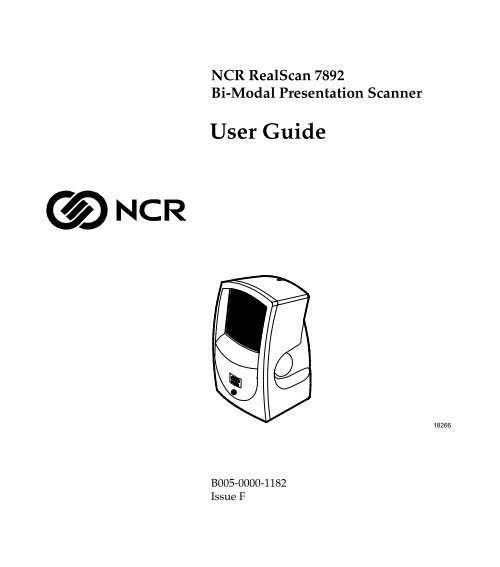
<strong>NCR</strong> <strong>RealScan</strong> <strong>7892</strong><br />
<strong>Bi</strong>-<strong>Modal</strong> <strong>Presentation</strong> <strong>Scanner</strong><br />
User Guide<br />
18266<br />
B005-0000-1182<br />
Issue F
The product described in this book is a licensed product of <strong>NCR</strong> Corporation.<br />
<strong>NCR</strong> is a registered trademark of <strong>NCR</strong> Corporation.<br />
<strong>NCR</strong> <strong>RealScan</strong> is a trademark of the <strong>NCR</strong> Corporation.<br />
It is the policy of <strong>NCR</strong> Corporation (<strong>NCR</strong>) to improve products as new technology, components, software,<br />
and firmware become available. <strong>NCR</strong>, therefore, reserves the right to change specifications without prior<br />
notice.<br />
All features, functions, and operations described herein may not be marketed by <strong>NCR</strong> in all parts of the<br />
world. In some instances, photographs are of equipment prototypes. Therefore, before using this document,<br />
consult with your <strong>NCR</strong> representative or <strong>NCR</strong> office for information that is applicable and current.<br />
To maintain the quality of our publications, we need your comments on the accuracy, clarity, organization,<br />
and value of this book.<br />
Address correspondence to:<br />
Manager, Information Products<br />
<strong>NCR</strong> Corporation<br />
2651 Satellite Blvd.<br />
Duluth, GA 30096<br />
Copyright © 2001, 2002, 2003<br />
By <strong>NCR</strong> Corporation<br />
Dayton, Ohio U.S.A.<br />
All Rights Reserved
i<br />
Preface<br />
Safety Warnings<br />
This book is for the various people who unpack, install, program,<br />
operate, and troubleshoot the <strong>NCR</strong> <strong>RealScan</strong> <strong>7892</strong> <strong>Bi</strong>-<strong>Modal</strong><br />
<strong>Presentation</strong> <strong>Scanner</strong>. It contains step-by-step instructions for each of<br />
these functions. Since the daily operation of the scanner is very simple,<br />
frequent references to this book are not required while using the<br />
scanner. However, this book is essential each time you perform the less<br />
frequently used functions such as installing and programming.<br />
Notice: This document is <strong>NCR</strong> proprietary information and is not to<br />
be disclosed or reproduced without consent.<br />
Safety Extra Low Voltage<br />
This device should only be powered by a Safety Extra Low Voltage<br />
(SELV) power supply source with an available current level of 5<br />
amperes or less, suitable for the country of installation. The power<br />
source must be certified by the appropriate safety agency for the<br />
country of installation.<br />
Le matériel doit être reliés electriquement au circuit å Très Basse<br />
Tension de Sécurité (TBTS) ayant une limite de 5 ampères<br />
correspondant de facon satisfaisante et acceptable dans le pays où le<br />
matériel doit être installé. Le source d’alimentation doit être approuvée<br />
par une agence de normalisation appropriée et acceptable dans le pays<br />
où le matériel doit être installé.
ii<br />
References<br />
• <strong>NCR</strong> <strong>RealScan</strong> <strong>7892</strong> <strong>Bi</strong>-<strong>Modal</strong> <strong>Presentation</strong> <strong>Scanner</strong> Installation/Owner<br />
Guide<br />
(497-0003071)<br />
• <strong>NCR</strong> <strong>Scanner</strong>/Scale Interface Programmer’s Guide<br />
(BD20-1074-A)<br />
• <strong>NCR</strong> <strong>RealScan</strong> <strong>7892</strong> <strong>Bi</strong>-<strong>Modal</strong> <strong>Presentation</strong> <strong>Scanner</strong> Parts Identification<br />
Manual<br />
(B005-0000-1184)<br />
• <strong>NCR</strong> <strong>Scanner</strong> Programming Tags<br />
(BST0-2121-74)<br />
• International Technical Specification – Symbology Identifiers<br />
(AIM International ITS, 02-2002<br />
http://www.aimglobal.org/aimstore/ordfrm.doc)
iii<br />
Table of Contents<br />
Chapter 1: Introduction<br />
Using Your <strong>Scanner</strong> ............................................... 1-2<br />
Laser Scanning........................................................ 1-3<br />
Chapter 2: Understanding the <strong>RealScan</strong> <strong>7892</strong><br />
Physical Considerations......................................... 2-1<br />
Environmental Considerations ............................. 2-2<br />
Power Considerations............................................ 2-3<br />
Chapter 3: Installation<br />
Preparing for Installation............................................. 3-1<br />
Unpack the Unit ..................................................... 3-1<br />
Inspect the Unit for Damage ................................. 3-1<br />
Verify you the have Correct Cables ...................... 3-2<br />
<strong>RealScan</strong> <strong>7892</strong>-0100 Standard Interface<br />
Cables.................................................................. 3-2<br />
<strong>RealScan</strong> <strong>7892</strong>-0100 USB Cables........................ 3-3<br />
<strong>RealScan</strong> <strong>7892</strong>-0200 Interface Cable.................. 3-3<br />
Determine <strong>Scanner</strong> Location ................................. 3-4<br />
Helpful Information ..................................................... 3-5<br />
Identifying Available Kits...................................... 3-5<br />
Determining the Communication Protocol.......... 3-6<br />
Default Setting........................................................ 3-7<br />
Installing the <strong>RealScan</strong> <strong>7892</strong>-0100/0300...................... 3-8<br />
Standard Interface Connection.............................. 3-8<br />
USB Interface Connection...................................... 3-9<br />
Installing the <strong>RealScan</strong> <strong>7892</strong>-0200 (Wedge) .............. 3-11<br />
Connecting Power ...................................................... 3-13
iv<br />
Modifying the <strong>Scanner</strong> Program ............................... 3-14<br />
Chapter 4: Operating Your <strong>Scanner</strong><br />
<strong>Scanner</strong> Components.................................................... 4-1<br />
<strong>Presentation</strong> Scanning.................................................. 4-2<br />
Pick-Up Scanning ......................................................... 4-4<br />
Label Orientation.......................................................... 4-5<br />
Scan Pattern Location............................................. 4-5<br />
PACESETTER......................................................... 4-5<br />
Single Line Scanning.............................................. 4-6<br />
Single Line Scanning Programmable Options ..... 4-7<br />
Single Action Switch Setting ............................. 4-7<br />
70% Line Width Option..................................... 4-7<br />
Label Rotation......................................................... 4-8<br />
Distance from <strong>Scanner</strong> ........................................... 4-9<br />
Read Indicators........................................................... 4-10<br />
Status Indicator..................................................... 4-10<br />
Audible Indicator ................................................. 4-10<br />
Indicator Functions .............................................. 4-11<br />
Bar Code Quality ........................................................ 4-12<br />
Reduced Space Symbology........................................ 4-13<br />
RSS-14.................................................................... 4-13<br />
RSS-14 Stacked...................................................... 4-13<br />
RSS Expanded....................................................... 4-14<br />
RSS Expanded Stacked ........................................ 4-14<br />
Taking Care of Your <strong>Scanner</strong>..................................... 4-15<br />
<strong>Scanner</strong> Operation Summary .................................... 4-16<br />
Scan the Bar Code Label ...................................... 4-16<br />
<strong>Presentation</strong> Scanning...................................... 4-16<br />
Pick-up Scanning.............................................. 4-16<br />
Single Line Scanning........................................ 4-16
v<br />
Observe the Read Indication ............................... 4-17<br />
Good Read Indication...................................... 4-17<br />
No Read Indication.......................................... 4-17<br />
Chapter 5: Programming<br />
On-Site Offering ..................................................... 5-1<br />
Depot Offering........................................................ 5-2<br />
Preparing for Your Program ................................. 5-2<br />
Completing the Worksheets .................................. 5-3<br />
Entering Your Program.......................................... 5-4<br />
Requirements.......................................................... 5-4<br />
Help......................................................................... 5-4<br />
Suggestion............................................................... 5-4<br />
Programming Considerations ..................................... 5-5<br />
Programming Tags................................................. 5-5<br />
Programming Mode............................................... 5-7<br />
Entering Your Program................................................ 5-8<br />
Default Settings............................................................. 5-9<br />
Communications Protocol (<strong>7892</strong>-0100 only)............. 5-10<br />
Good Read Tone......................................................... 5-11<br />
Tone On/Off......................................................... 5-11<br />
Tone Length.......................................................... 5-11<br />
Tone Volume ........................................................ 5-11<br />
Parameter Shortcuts............................................. 5-12<br />
Timers.......................................................................... 5-13<br />
Lockout Time........................................................ 5-13<br />
Restart Lockout Timer ......................................... 5-13<br />
Active Time........................................................... 5-14<br />
Parameter Shortcuts............................................. 5-14<br />
Bar Codes - 1 ............................................................... 5-15<br />
UPC/EAN............................................................. 5-15
vi<br />
Extend UPC-A to EAN-13 ............................... 5-15<br />
Periodical Codes............................................... 5-16<br />
Periodical Code Extension............................... 5-16<br />
Send Data.......................................................... 5-16<br />
Parameter Shortcuts............................................. 5-17<br />
Bar Codes - 2 ............................................................... 5-18<br />
Code 39.................................................................. 5-18<br />
Minimum Characters Allowed ....................... 5-18<br />
Full ASCII ......................................................... 5-18<br />
Check Digit Present.......................................... 5-19<br />
Transmit Check Digit....................................... 5-19<br />
Allow Single Character Tags........................... 5-19<br />
Parameter Shortcuts............................................. 5-19<br />
Bar Codes - 3 ............................................................... 5-20<br />
Interleaved 2 of 5.................................................. 5-20<br />
Bar Code Length............................................... 5-20<br />
Value 1 and Value 2 ......................................... 5-21<br />
Check Digit Present.......................................... 5-21<br />
Transmit Check Digit....................................... 5-21<br />
Parameter Shortcuts............................................. 5-21<br />
Bar Codes - 4 ............................................................... 5-22<br />
Code 128................................................................ 5-22<br />
Minimum Data Characters Allowed................... 5-22<br />
UCC 128 ................................................................ 5-22<br />
Parameter Shortcuts............................................. 5-23<br />
Bar Codes - 5 ............................................................... 5-24<br />
Enable RSS ............................................................ 5-24<br />
Scans Required on RSS 14.................................... 5-24<br />
Scans Required on RSS 14 E ................................ 5-24<br />
USS-128 Emulation Mode.................................... 5-25<br />
Parameter Shortcuts............................................. 5-25
vii<br />
Label Identifiers.......................................................... 5-26<br />
Identifier Type...................................................... 5-26<br />
Default Prefix and Default Suffix.................... 5-27<br />
None.................................................................. 5-27<br />
Unique Prefix and Unique Suffix.................... 5-27<br />
AIM Identifiers................................................. 5-29<br />
Common Byte 1 and Common Byte 2................. 5-30<br />
Bar Code Type...................................................... 5-30<br />
Common Byte....................................................... 5-31<br />
Unique Identifier.................................................. 5-31<br />
Parameter Shortcuts............................................. 5-32<br />
Additional Bar Code Options.................................... 5-33<br />
UPC Number System Character ......................... 5-33<br />
ISBN Format ......................................................... 5-33<br />
RS-232 Parameters - 1................................................. 5-34<br />
Baud Rate.............................................................. 5-34<br />
Parity ..................................................................... 5-34<br />
Stop <strong>Bi</strong>ts And Character Length ......................... 5-34<br />
Handshake............................................................ 5-35<br />
Parameter Shortcuts............................................. 5-35<br />
RS-232 Parameters - 2................................................. 5-36<br />
BCC Option........................................................... 5-36<br />
Interface Control................................................... 5-36<br />
Check Digit ........................................................... 5-37<br />
Retransmit On ACK Timer Expiration ............... 5-37<br />
Parameter Shortcuts............................................. 5-37<br />
RS-232 Prefix Byte....................................................... 5-38<br />
Prefix Byte............................................................. 5-38<br />
ASCII Code........................................................... 5-38<br />
Parameter Shortcuts............................................. 5-38<br />
RS-232 Terminator Byte ............................................. 5-39
viii<br />
Terminator Byte.................................................... 5-39<br />
ASCII Code........................................................... 5-39<br />
Second Terminator Byte....................................... 5-39<br />
Parameter Shortcuts............................................. 5-40<br />
Communications Options.......................................... 5-41<br />
Send IBM Tags in Hex or ASCII.......................... 5-41<br />
Maintain or Drop OCIA Message Data/Retries<br />
on IBM................................................................... 5-41<br />
RS-232 Mode: Normal or Eavesdrop .................. 5-42<br />
RS-232 Delay......................................................... 5-42<br />
OCIA <strong>NCR</strong> Short Soft Reset ................................ 5-43<br />
Single Line Scanning (option).................................... 5-44<br />
Switch Activation ................................................. 5-44<br />
Line Width............................................................ 5-44<br />
Parameter Version Number....................................... 5-45<br />
Wedge Options........................................................... 5-46<br />
Country Code ....................................................... 5-46<br />
Caps Lock.............................................................. 5-46<br />
Number Lock and Keypad.................................. 5-46<br />
Intercharacter Delay............................................. 5-47<br />
Parameter Shortcuts............................................. 5-47<br />
<strong>Scanner</strong> Programming Summary.............................. 5-48<br />
Creating the Program........................................... 5-48<br />
Entering the Program........................................... 5-48<br />
Saving the Program.............................................. 5-49<br />
USB Programming...................................................... 5-50<br />
RS-232 Communications...................................... 5-50<br />
IBM Communications.......................................... 5-51<br />
Chapter 6: Troubleshooting<br />
Repairing Your <strong>RealScan</strong> <strong>7892</strong>..................................... 6-4<br />
Fuse (old cable only)..................................................... 6-5
ix<br />
Chapter 7: Program Defaults/Worksheets<br />
Identifying Program Defaults ............................... 7-1<br />
Using the Programming Worksheets.................... 7-3<br />
Programming Worksheets..................................... 7-4<br />
ASCII Code Chart ............................................ 7-22<br />
Index
x<br />
Revision Record<br />
Issue Date<br />
Remarks<br />
A November 2000 First issue<br />
B June 2001 Corrections: Page 2, LED Indicator colors.<br />
Worksheet 30 and 10.<br />
C October 2001 Wedge Option added<br />
D November 2001 Added USB Connection<br />
E September 2002 Added AIM Label Identifier<br />
F April 2003 Added Reduced Space Symbology (RSS)<br />
support
xi<br />
Radio Frequency Interference Statements<br />
Federal Communications Commission (FCC)<br />
Information to User<br />
This equipment has been tested and found to comply with the limits for a Class A<br />
digital device, pursuant to Part 15 of FCC Rules. These limits are designed to provide<br />
reasonable protection against harmful interference when the equipment is operated in<br />
a commercial environment. This equipment generates, uses, and can radiate radio<br />
frequency energy and, if not installed and used in accordance with the instruction<br />
manual, may cause harmful interference to radio communications. Operation of this<br />
equipment in a residential area is likely to cause interference in which case the user<br />
will be required to correct the interference at his own expense.<br />
<strong>NCR</strong> is not responsible for any radio or television interference caused by unauthorized<br />
modification of this equipment or the substitution or attachment of connecting cables<br />
and equipment other than those specified by <strong>NCR</strong>. The correction of interference<br />
caused by such unauthorized modification, substitution or attachment will be the<br />
responsibility of the user. The user is cautioned that changes or modifications not<br />
expressly approved by <strong>NCR</strong> may void the user’s authority to operate the equipment.<br />
Canadian Department of Communications<br />
This digital apparatus does not exceed the Class A limits for radio noise emissions<br />
from digital apparatus set out in the Radio Interference Regulations of the Canadian<br />
Department of Communications.<br />
Le présent appareil numérique n’émet pas de bruits radioélectriques dépassant les<br />
limites applicables aux appareils numériques de la classe A prescrites dans le<br />
Règlement sur le brouillage radioélectriques édicté par le ministrère des<br />
Communications du Canada.<br />
Voluntary Control Council For Interference (VCCI)
xii<br />
International Radio Frequency Interference Statement<br />
Warning: This is a Class A product. In a domestic environment this<br />
product may cause radio interference, in which case the user may be<br />
required to take adequate measures.
xiii<br />
Laser Safety<br />
Laser Safety Label<br />
The <strong>NCR</strong> <strong>RealScan</strong> <strong>7892</strong> <strong>Bi</strong>-<strong>Modal</strong> <strong>Presentation</strong> <strong>Scanner</strong> comes from the<br />
factory with the Laser Safety label attached. The following figure<br />
shows the Laser Safety label and its location.<br />
Made in Ireland<br />
Made in Ireland<br />
17780<br />
IEC Class 1 Laser Identification<br />
The <strong>NCR</strong> <strong>RealScan</strong> <strong>7892</strong> <strong>Bi</strong>-<strong>Modal</strong> <strong>Presentation</strong> <strong>Scanner</strong> comes from the<br />
factory with the Laser Safety Warning and the Class Identification<br />
molded in the case.<br />
Class II a Laser<br />
Product. Avoid<br />
Long-Term Viewing<br />
of direct Laser Light<br />
Clase II a Producto<br />
Laser. Trate de no ver<br />
directamente el Rayo<br />
Laser por mucho tiempo<br />
Apparell a laser de<br />
classe II a. eviter toute<br />
exposition prolongee<br />
de la vue a la lumiere<br />
laser directe.<br />
IEC CLASS 1<br />
LASER PRODUCT<br />
17781<br />
The <strong>NCR</strong> <strong>RealScan</strong> <strong>7892</strong> <strong>Bi</strong>-<strong>Modal</strong> <strong>Presentation</strong> <strong>Scanner</strong> is a Class 1<br />
Laser Product.
xiv<br />
Laser Power<br />
The <strong>NCR</strong> <strong>RealScan</strong> <strong>7892</strong> <strong>Bi</strong>-<strong>Modal</strong> <strong>Presentation</strong> <strong>Scanner</strong> meets the<br />
following laser/LED power requirements.<br />
• Class IIa CDRH (Center for Devices and Radiological Health)<br />
• “Class IIa Laser Product—Avoid Long-Term Viewing of Direct<br />
Laser Light.”<br />
• Class 1 EN60-825 (Europäische Norm)<br />
Following is the radiant energy of the laser/LED light as applied to<br />
each of the specified requirements.<br />
Caution: The <strong>NCR</strong> <strong>RealScan</strong> <strong>7892</strong> <strong>Bi</strong>-<strong>Modal</strong> <strong>Presentation</strong> <strong>Scanner</strong> is<br />
not intended for long-term viewing of the direct laser light. However,<br />
the unit is safe if used as intended.<br />
Accessible Emission Limit (CDRH Calculation)<br />
Accessible Emission Limit EN60 825-1:1994+AII:1996<br />
0.66 Milliwatts<br />
0.63 Milliwatts<br />
Caution: Use of controls or adjustments or performance of procedures<br />
other than specified herein may result in hazardous radiation<br />
exposure.
xv<br />
Declaration of Conformity<br />
We, <strong>NCR</strong> Corporation, Retail Solutions Division Atlanta, 2651 Satellite<br />
Boulevard, Duluth, Georgia, 30096-5810, USA, declare under our sole<br />
responsibility that the product Class <strong>RealScan</strong> <strong>7892</strong> Bar Code <strong>Bi</strong>-<strong>Modal</strong><br />
<strong>Presentation</strong> <strong>Scanner</strong> to which this declaration relates is in conformity<br />
with the following standard or other normative document(s) following<br />
the provisions of the noted Directives.<br />
EU Directive<br />
Harmonized Standard(s)<br />
89/336/EEC (EMC) EN 55022: 1994 + A1 (1995) + A2 (1997)<br />
EN 50082-1, Part 1 (1992)<br />
IEC 801-2: 1984, Severity Level 3<br />
IEC 801-3: 1984, Severity Level 2<br />
IEC 801-4: 1988. Severity Level 2<br />
72/23/EEC (Low Voltage) EN 60950: 1992 A1, A2, A3, A4, and A11<br />
EN 60825-1<br />
European Contact<br />
<strong>NCR</strong> Corporation<br />
EU Patent Attorney<br />
RSG – Atlanta<br />
<strong>NCR</strong> Limited<br />
2651 Satellite Boulevard 206 Marylebone Road<br />
Duluth, GA 30096-5810<br />
London NW1 6LY<br />
U.S.A<br />
England
Chapter 1: Introduction<br />
Your new <strong>RealScan</strong> <strong>7892</strong> <strong>Bi</strong>-<strong>Modal</strong> <strong>Presentation</strong> <strong>Scanner</strong> represents the<br />
latest technology in laser scanning. It is a small, compact unit that<br />
weighs about 9.6 ounces. Being a presentation scanner, it permits you<br />
to present the bar code label to the scanner. This eliminates the need to<br />
move the label past the scan window, reducing the amount of operator<br />
activity. The <strong>RealScan</strong> <strong>7892</strong> also has good pass-by-scanning capability,<br />
for those to whom pass-by motion seems more natural.<br />
The <strong>RealScan</strong> <strong>7892</strong> is available in two models: <strong>7892</strong>-0100 and <strong>7892</strong>-0200.<br />
The <strong>7892</strong>-0100 offers IBM, RS-232, and OCIA communication, and<br />
permits you to change among these three programming types. It can be<br />
connected to the host terminal through a standard interface connection<br />
or through a USB connection.<br />
Power for the <strong>RealScan</strong> <strong>7892</strong> is provided through a wall adapter Power<br />
Module or directly from the host terminal. In either case, the input<br />
voltage to the <strong>NCR</strong> <strong>7892</strong> must be +12Vdc.<br />
The <strong>RealScan</strong> <strong>7892</strong>-0200 offers PC Keyboard Wedge communication<br />
only. This model is designed to address the needs of retailers whose<br />
point-of-sale application does not accept scan data through a<br />
communication port.
1-2 Chapter 1: Introduction<br />
Using Your <strong>Scanner</strong><br />
Because your <strong>RealScan</strong> <strong>7892</strong> is a hands-free presentation type scanner,<br />
it is much easier to use in the retail environment. The scanner sits on<br />
the counter and you present the bar code label to the scanner.<br />
Although the <strong>RealScan</strong> <strong>7892</strong> is a presentation scanner, there may be<br />
times when the merchandise is too large to be presented to the scanner.<br />
In these cases, you can pick up the scanner and move it to the<br />
merchandise. Because the scanner is very light, you can maneuver it<br />
easily in these circumstances.<br />
Single Line Scanning is an optional feature of the <strong>RealScan</strong> <strong>7892</strong>-<br />
0100/0200. This feature permits you to scan a specific bar code in a<br />
group of bar codes.<br />
The design of your scanner permits it to sit on a counter top. Your<br />
<strong>RealScan</strong> <strong>7892</strong> does not have an On/Off switch. To minimize the<br />
amount of time the laser is on, the laser is pulsed during idle. If you<br />
present a label to the scanner when it is idle, it detects the label and<br />
turns on. This occurs with minimal delay in reading the label. After<br />
several minutes of not detecting a valid bar code, the laser<br />
(programmable 5-30 minutes) shuts off.
Chapter 1: Introduction 1-3<br />
Laser Scanning<br />
Although the <strong>RealScan</strong> <strong>7892</strong> is very simple to use, it is quite a complex<br />
electronic device. It contains a laser module that generates a low-level<br />
laser light. The laser light passes through a series of mirrors to generate<br />
a scan pattern. Reflected light from the bar code is collected and<br />
decoded to determine the bar code data. The scanner then sends the<br />
information to the host terminal or personal computer (PC).<br />
The <strong>RealScan</strong> <strong>7892</strong> produces an omnidirectional scan pattern that<br />
makes scanning easier. The pattern looks like several lines are scanning<br />
simultaneously, but is actually just a single beam reflected through<br />
several mirrors. It is this pattern that enables the scanner to read bar<br />
codes from most orientations.<br />
After reading the information contained in the bar code, the <strong>RealScan</strong><br />
<strong>7892</strong> sends the information to the host terminal or PC. Interfaces<br />
available with the <strong>RealScan</strong> <strong>7892</strong>-0100 for transmitting information are<br />
OCIA <strong>NCR</strong> Short, OCIA <strong>NCR</strong> Long, OCIA Non-<strong>NCR</strong>, RS-232, IBM<br />
468x/469x, IBM-USB or <strong>NCR</strong>/RS-232 USB using a USB Dongle. The<br />
<strong>RealScan</strong> <strong>7892</strong>-0200 supports Keyboard Wedge, although using<br />
different cables. The <strong>RealScan</strong> <strong>7892</strong> contains all the necessary<br />
electronics and firmware for each of these interfaces. When installing<br />
the scanner, you can change the interface selection, if needed. Refer to<br />
Chapter 5, Programming and Chapter 6, Troubleshooting.
Chapter 2: Understanding the <strong>RealScan</strong> <strong>7892</strong><br />
Your <strong>RealScan</strong> <strong>7892</strong> is designed to operate within a wide<br />
environmental range. Being a small peripheral unit, it does not require<br />
any special wiring or mounting. Normally, its requirements are within<br />
those of the host terminal or PC.<br />
Physical Considerations<br />
The <strong>RealScan</strong> <strong>7892</strong> is a small, lightweight unit. Weighing 9.6 ounces, it<br />
is remarkably easy to pick up when necessary. The <strong>RealScan</strong> <strong>7892</strong><br />
requires minimal counter space as shown below:<br />
140 mm<br />
(5.5 in.)<br />
140 mm<br />
(5.5 in.)<br />
89 mm<br />
(3.5 in.)<br />
89 mm<br />
(3.5 in.)<br />
17598
2-2 Chapter 2: Understanding the <strong>RealScan</strong> <strong>7892</strong><br />
Environmental Considerations<br />
Your <strong>RealScan</strong> <strong>7892</strong> operates in all standard-working environments.<br />
Temperature and humidity ranges permitted are greater when the<br />
<strong>RealScan</strong> <strong>7892</strong> is in storage or transit. The following table gives the<br />
various environmental requirements.<br />
Working Range<br />
Storage Range<br />
Temperature 50°F to 104°F<br />
10°C to 40°C<br />
-40°F to 140°F<br />
-40°C to 60°C<br />
Temperature Change 18°F per hour<br />
10°C per hour<br />
36°F per hour<br />
20°C per hour<br />
Humidity<br />
20% to 80% RH Non-5% to 95% RH Non-<br />
Condensing Condensing<br />
Humidity Change 10% per hour<br />
Barometric Pressure 105 x 10 3 Pa<br />
to 69 x 10 3 Pa<br />
Ambient Light 300 Foot-candles on Not Applicable<br />
tag, scanner not<br />
pointed at light<br />
source<br />
Acoustical Noise 50 dBa or less Not Applicable<br />
measured at 12 in.<br />
(30.48 cm) from any<br />
surface<br />
Vibration and Shock Can withstand multiple 6 ft. (183 cm) drops onto<br />
a tiled concrete floor
Chapter 2: Understanding the <strong>RealScan</strong> <strong>7892</strong> 2-3<br />
Power Considerations<br />
Your <strong>RealScan</strong> <strong>7892</strong> operates on only 9 Vdc. It receives current through<br />
the <strong>Scanner</strong> Module Cable from a power module that plugs into an<br />
electrical outlet. One of five power modules comes with your scanner,<br />
depending on the requirements you specify. It is critical that you have<br />
the proper power module for your electrical circuit. The following<br />
power modules are available:<br />
• 104 Vac to 127 Vac, 60 Hz, USA/Canada<br />
• 220 Vac to 240 Vac, 50 Hz, European<br />
• 220 Vac to 240 Vac, 50 Hz, Australia<br />
• 90 Vac to 104 Vac, 50/60 Hz, Japan<br />
• 220 Vac to 240 Vac, 50 Hz, United Kingdom
Chapter 3: Installation<br />
Preparing for Installation<br />
Unpack the Unit<br />
There are several things you should do when preparing to install a<br />
<strong>RealScan</strong> <strong>7892</strong>. Each of these is discussed in the following sections.<br />
Unpack the unit according to the instructions printed on the box. After<br />
everything is out of the box, take inventory to ensure that you have<br />
received all components. The following list identifies the package<br />
contents.<br />
• <strong>RealScan</strong> <strong>7892</strong> scanner<br />
• Power Module (if ordered)<br />
• <strong>Scanner</strong> Module Cable<br />
• Interface Cable (if ordered)<br />
• Documentation<br />
Inspect the Unit for Damage<br />
Inspect the unit for physical damage: broken or scratched scan<br />
window, broken or scratched cabinet, and so forth. If your scanner has<br />
been damaged due to shipping, notify the shipping carrier and your<br />
<strong>NCR</strong> representative. If you find other damage, notify <strong>NCR</strong> or the other<br />
supplier if not purchased directly from <strong>NCR</strong>.
3-2 Chapter 3: Installation<br />
Verify you the have Correct Cables<br />
Identify the communication protocol required by the host terminal and<br />
compare this with the cables shipped with the scanner. The <strong>RealScan</strong><br />
<strong>7892</strong> comes from the factory programmed for RS-232 unless specified<br />
otherwise when ordered.<br />
<strong>RealScan</strong> <strong>7892</strong>-0100 Standard Interface Cables<br />
The following table identifies the most common interface cables<br />
required for the different host connections that can be made with the<br />
<strong>RealScan</strong> <strong>7892</strong>-0100. See your <strong>NCR</strong> representative for additional<br />
<strong>RealScan</strong> <strong>7892</strong>-0100 cables.<br />
Interface Cable<br />
Host Connection<br />
Interface Corporate ID No.<br />
DynaKey Wedge RS-232 1416-C686-0030<br />
9-Pin I/F Cable RS-232 1416-C546-0030<br />
IBM 468 x – 9B RS-485 1416-C547-0030<br />
9 Pin Power/Interface Combo RS-232 1416-C643-0030<br />
Note: You can also interface your <strong>RealScan</strong> <strong>7892</strong> to other host terminals<br />
not shown in the previous list. You normally do this by using RS-232<br />
communications through a keyboard wedge. Your application may also<br />
require a software wedge.
Chapter 3: Installation 3-3<br />
<strong>RealScan</strong> <strong>7892</strong>-0100 USB Cables<br />
The following table identifies the USB cables required for connecting<br />
the <strong>RealScan</strong> <strong>7892</strong>-0100 to a USB port on the host terminal. Note that a<br />
<strong>Scanner</strong> Cable is required to connect the scanner to the USB Adapter<br />
Cable.<br />
Cable Type Corporate ID No.<br />
Dongle USB Adapter Powered, Latching 1416-C731-0004<br />
Cable<br />
Dongle USB Adapter<br />
Cable<br />
Unpowered, Nonlatching<br />
1416-C732-0004<br />
When using 1416-C731-0004, the <strong>RealScan</strong> <strong>7892</strong> receives power from<br />
the host terminal. Do not connect a Power Module to the Interface Box<br />
on the end of the Dongle Adapter Cable.<br />
<strong>RealScan</strong> <strong>7892</strong>-0200 Interface Cable<br />
The following table identifies the most common interface cable<br />
required for the <strong>RealScan</strong> <strong>7892</strong>-0200 (Wedge) scanner. See your <strong>NCR</strong><br />
representative for additional <strong>RealScan</strong> <strong>7892</strong>-0200 cables.<br />
Interface Cable<br />
Host Connection<br />
Interface Corporate ID No.<br />
PC/AT Keyboard Wedge Wedge 1416-C636-0030
3-4 Chapter 3: Installation<br />
Determine <strong>Scanner</strong> Location<br />
When identifying a location for your <strong>RealScan</strong> <strong>7892</strong> scanner, consider<br />
the length of the connecting cables. The electrical outlet used for the<br />
Power Module can be approximately 74 in. (188 cm) from the host<br />
terminal. Depending on the <strong>Scanner</strong> Module Cable, the scanner can be<br />
approximately 9 ft. (274 cm) from the host terminal or PC. These<br />
distances are normally shorter depending on how you route the<br />
connecting cables. Be sure that the <strong>Scanner</strong> Module Cable is long<br />
enough to permit the scanner to be picked up when required for large<br />
packages.<br />
Like any electronic device, your <strong>RealScan</strong> <strong>7892</strong> should not be located in<br />
direct sunlight. Temperatures above 104 degrees Fahrenheit (40<br />
degrees Celsius) can occur when sunlight falls on objects through<br />
windows or on an outdoor checkstand.
Chapter 3: Installation 3-5<br />
Helpful Information<br />
Because the <strong>RealScan</strong> <strong>7892</strong> is so versatile, additional information is<br />
provided to help have a successful installation. Although this<br />
information is not needed for most installations, it is needed in certain<br />
instances.<br />
Identifying Available Kits<br />
A Power Module for the electrical requirements you specified comes<br />
with the <strong>RealScan</strong> <strong>7892</strong>. However, replacement Power Modules are<br />
available.<br />
The following table identifies the kit number for all available kits.<br />
Kit Description<br />
Kit Number<br />
Power Module, 104-127 Vac, 60 Hz, North American <strong>7892</strong>-K011-V002<br />
& Japanese<br />
Power Module, 104-127 Vac, 60 Hz, North American <strong>7892</strong>-K012-V001<br />
Power Module, 220-240 Vac, 50 Hz, European<br />
Power Module, 220-240 Vac, 50 Hz, Australia<br />
Power Module, 240 Vac, 50 Hz, United Kingdom<br />
Auxiliary Power Cable<br />
(7450 Only Model 0XXX, 1XXX))<br />
Auxiliary Power Cable<br />
(7450 Only Model 24xx)<br />
Auxiliary Power Cable<br />
(7452 only)<br />
Kit- Auxiliary Power, IBM 468-9B (Remote Power)<br />
<strong>7892</strong>-K014-V001<br />
<strong>7892</strong>-K015-V001<br />
<strong>7892</strong>-K016-V001<br />
<strong>7892</strong>-K051-V001<br />
<strong>7892</strong>-K052-V001<br />
<strong>7892</strong>-K053-V001<br />
<strong>7892</strong>-K054-V001
3-6 Chapter 3: Installation<br />
Determining the Communication Protocol<br />
Before connecting your <strong>RealScan</strong> <strong>7892</strong> to a host terminal or PC, you<br />
must verify the communication protocol being used. The <strong>RealScan</strong> <strong>7892</strong><br />
comes from the factory pre-programmed per order requirements. An<br />
optional sheet is included with the unit that explains how the unit is<br />
programmed when it is shipped. However, the communications<br />
protocol is easily changed. Refer to Chapter 5, Programming and<br />
Chapter 6, Troubleshooting. Also, be sure that the application program<br />
running on your host terminal or PC can communicate with the<br />
<strong>RealScan</strong> <strong>7892</strong>. Use the following procedure if you need to determine<br />
the communications protocol programmed in your <strong>RealScan</strong> <strong>7892</strong>.<br />
1. Apply power to the <strong>RealScan</strong> <strong>7892</strong>.<br />
2. Scan the Diagnostics tag. (Must be the first tag scanned after<br />
applying power.)<br />
3. Scan the Hex 3 tag. The good read tone for this tag sounds (three<br />
beeps).<br />
The Status Indicator flashes green and the tone beeps, identifying the<br />
communications protocol. The following table identifies the number of<br />
beeps that sound for each communication protocol.<br />
Tone<br />
Communication Protocol<br />
1 short, OCIA <strong>NCR</strong> Short<br />
1 Beep OCIA <strong>NCR</strong> Long<br />
2 Beeps OCIA Non-<strong>NCR</strong><br />
3 Beeps IBM 468x - Addr 4A<br />
4 Beeps IBM 468x - Addr 4B (1520 Bar Code Reader)<br />
5 Beeps RS-232<br />
6 Beeps IBM 468x - Addr 4B (Hand Held Bar Code Reader)<br />
7 Beeps Wedge<br />
4. Remove power from the <strong>RealScan</strong> <strong>7892</strong>.
Chapter 3: Installation 3-7<br />
Default Setting<br />
Your scanner is shipped in one of eight default modes depending on<br />
the cable interface included with the unit. To determine the interface<br />
you have and set the default:<br />
• Scan the Default tag.<br />
• The scanner gives one long beep and then beeps the same number<br />
of times as the protocol options explained above.<br />
Note: Seven of the default and protocol modes are applicable to the<br />
<strong>RealScan</strong> <strong>7892</strong>-0100. Only one mode, Wedge, is applicable to the<br />
<strong>RealScan</strong> <strong>7892</strong>-0200.
3-8 Chapter 3: Installation<br />
Installing the <strong>RealScan</strong> <strong>7892</strong>-0100/0300<br />
The <strong>RealScan</strong> <strong>7892</strong> can be connected to the host terminal through a<br />
standard interface connection or through a USB connection. Power for<br />
the <strong>RealScan</strong> <strong>7892</strong> is provided through a wall adapter Power Module<br />
or directly from the host terminal<br />
Standard Interface Connection<br />
In most configurations the <strong>Scanner</strong> Cable connects the <strong>RealScan</strong> <strong>7892</strong> to<br />
your host terminal. Refer to the terminal documentation for<br />
information about connecting this cable. Some terminals require a<br />
trained technician to perform this function. If a Power Module is<br />
required, it connects to a connector on the <strong>Scanner</strong> Cable.<br />
Some less common configurations require two cables: a <strong>Scanner</strong> Cable<br />
and an Interface Cable. If a Power Module is required for this<br />
configuration, it connects to the box on the end of the <strong>Scanner</strong> Cable.<br />
Host Terminal<br />
<strong>Scanner</strong><br />
Cable<br />
Host Terminal<br />
Interface<br />
Cable<br />
<strong>7892</strong><br />
Power<br />
Module<br />
<strong>7892</strong> Power<br />
Module<br />
<strong>Scanner</strong> Cable<br />
Most Common Configuration<br />
Uses <strong>7892</strong> <strong>Scanner</strong> Cable<br />
<strong>Scanner</strong> Cable<br />
Less Common Configuration<br />
Uses 7890 <strong>Scanner</strong> Cable<br />
Uses 7890 Interface Cable<br />
20582<br />
Note: The Power Module is not used if the <strong>RealScan</strong> <strong>7892</strong> receives<br />
power from the host terminal.
Chapter 3: Installation 3-9<br />
USB Interface Connection<br />
Connecting a <strong>RealScan</strong> <strong>7892</strong> to a USB port on a host terminal requires<br />
two special cables. One end of the Dongle Adapter Cable connects to<br />
the host terminal. The other end has an Interface Box that contains a<br />
printed circuit board with all the necessary circuitry. A <strong>Scanner</strong> Cable<br />
connects the <strong>RealScan</strong> <strong>7892</strong> to this box.<br />
Note: The Power Module is not used. The <strong>RealScan</strong> <strong>7892</strong> receives<br />
power from the host terminal.<br />
Host Terminal <strong>NCR</strong> <strong>7892</strong><br />
Interface Box<br />
<strong>Scanner</strong> Cable<br />
Dongle Adapter Cable<br />
20581<br />
J3 in the Interface Box on the end of the Dongle Adapter Cable contains<br />
a shunt that must be correctly installed for the host terminal. The cable<br />
is shipped from the factory with the shunt on pins 3 and 4. The<br />
following positions are available.<br />
• Pins 1 & 2 – Not used<br />
• Pins 3 & 4 – IBM<br />
• Pins 5 & 6 – <strong>NCR</strong>/RS-232<br />
• Pins 7 & 8 – Not used
3-10 Chapter 3: Installation<br />
The cover on the Interface Box latches together along one side.<br />
Carefully pry open the latched edge to open the Interface Box. Check<br />
the shunt position on J3 and change as needed. Close the Interface Box<br />
cover.<br />
J3<br />
W I R H<br />
1<br />
2<br />
7<br />
8<br />
C1<br />
R4<br />
R5<br />
J3<br />
J2<br />
U1<br />
R6<br />
R7<br />
U6<br />
U4<br />
C6<br />
C5<br />
C4<br />
J5<br />
U2<br />
C3<br />
C2<br />
U5<br />
U7<br />
J1<br />
R3<br />
R2<br />
R1<br />
Y1<br />
U3<br />
C7<br />
J4<br />
C8<br />
19573
Chapter 3: Installation 3-11<br />
Installing the <strong>RealScan</strong> <strong>7892</strong>-0200 (Wedge)<br />
The <strong>RealScan</strong> 7982-0200 (Wedge) option permits the <strong>RealScan</strong> <strong>7892</strong> to<br />
be connected to the host terminal through a keyboard connector. Scan<br />
data is input into the keyboard port. When connected in this<br />
configuration the <strong>RealScan</strong> <strong>7892</strong> cannot receive commands from the<br />
host terminal.<br />
Note: Unlike the <strong>RealScan</strong> <strong>7892</strong>-0100 there is only a single transmit<br />
message buffer in the <strong>RealScan</strong> <strong>7892</strong>-0200wedge use. The transmission<br />
of the data is significantly longer than other communication protocols<br />
and can be quite slow if a long intercharacter delay is required.<br />
Note: The Keyboard Wedge cable connects both the scanner and the<br />
keyboard to the host terminal through the keyboard port. This cable<br />
has two PS/2 connectors. If the Host terminal system has an AT<br />
keyboard connector, two adapters are required: an AT to PS/2 and a<br />
PS/2 to AT. These adapters are available locally at most computer<br />
stores.<br />
• Belkin F2N017 – AT to PS/2<br />
• Belkin F2N018 – PS/2 to AT
3-12 Chapter 3: Installation<br />
Keyboard Wedge Cable<br />
1416-C636-0030(<strong>7892</strong>-0200)<br />
Host Terminal<br />
Keyboard<br />
<strong>Scanner</strong> Cable<br />
Power Cable<br />
<strong>7892</strong> <strong>Scanner</strong><br />
Power<br />
Module<br />
19183a
Chapter 3: Installation 3-13<br />
Connecting Power<br />
1. Verify that you have the correct Power Module for your electrical<br />
outlet.<br />
2. Connect the power connector to the Interface Cable. Depending on<br />
the installation, this may be a connector on the cable or a box on the<br />
end of the cable.<br />
3. Plug the Power Module into an electrical outlet. When the <strong>RealScan</strong><br />
<strong>7892</strong> receives power, the diagnostics checks various hardware<br />
components. If the scanner passes the diagnostic tests, it gives a<br />
"ready" indication (four flashes of the Status Indicator). A green<br />
flash followed by a red flash is normal and indicates the scanner<br />
serial number is stored in the scanner’s EPROM.<br />
Note: If the <strong>RealScan</strong> <strong>7892</strong> is receiving power from the host terminal,<br />
do not connect the Power Module.<br />
Warning: When the host terminal powers the <strong>RealScan</strong> <strong>7892</strong>, do not<br />
plug the unit in live. This can cause the Power Supply in the<br />
terminal to shut down and may also blow an internal fuse in the<br />
terminal. Be sure to turn off the power to the host terminal before<br />
connecting the <strong>RealScan</strong> <strong>7892</strong>.
3-14 Chapter 3: Installation<br />
Modifying the <strong>Scanner</strong> Program<br />
Your <strong>RealScan</strong> <strong>7892</strong> comes from the factory with all programming<br />
parameters set to default values. To change any values that do not<br />
match your system requirements, refer to Chapter 5, Programming and<br />
Chapter 7, Program Defaults/Worksheets.<br />
Note: When using USB cables to connect the <strong>RealScan</strong> <strong>7892</strong> to a host<br />
terminal, some of the RS-232 parameters must be set in a specific way.<br />
Refer to the “USB Programming” section in Chapter 5, Programming.
Chapter 4: Operating Your <strong>Scanner</strong><br />
<strong>Scanner</strong> Components<br />
Before using your <strong>RealScan</strong> <strong>7892</strong>, you need to be familiar with some of<br />
its components. The figure below shows the scanner and identifies<br />
some of the parts and features.<br />
Status Indicator<br />
<strong>Scanner</strong> Module Cable<br />
Scan Window<br />
Single Line Button<br />
Speaker<br />
18276a
4-2 Chapter 4: Operating Your <strong>Scanner</strong><br />
<strong>Presentation</strong> Scanning<br />
<strong>Presentation</strong> scanning is much different from that used at checkout<br />
stands, such as in grocery stores. In the checkout stand environment,<br />
normally large quantities of items must be scanned in a short amount<br />
time. Therefore, you pass the items over the scanner, moving them<br />
from one side of the checkstand to another. The scanner reads the label<br />
while the items are moving by.<br />
With presentation scanning, you simply present the label to the<br />
scanner and then remove it. Do not move the label past the scanner, but<br />
to the scanner. <strong>Presentation</strong> scanning is particularly useful in a retail<br />
environment where the number of items associated with each<br />
transaction is normally small. There are three simple steps to<br />
presentation scanning.<br />
1. Move the bar code label to the scanner as shown.<br />
Scan Window<br />
17682
Chapter 4: Operating Your <strong>Scanner</strong> 4-3<br />
2. Position the bar code label completely within the red Laser Scan<br />
Pattern as indicated below. Normally the bar code should be three<br />
to four inches from the scanner. When the label is read the Status<br />
Indicator turns green, then returns to red. If enabled, a Good Read<br />
Tone also sounds.<br />
Status<br />
Indicator<br />
Laser Scan<br />
Pattern<br />
17684<br />
3. Move the bar code label away from the scanner as shown. The<br />
scanner is now ready to read another bar code label. To read<br />
another bar code, simply perform these three steps again.<br />
17685
4-4 Chapter 4: Operating Your <strong>Scanner</strong><br />
Pick-Up Scanning<br />
Occasionally you have merchandise that cannot be picked-up and<br />
presented to the scanner. The package may be too heavy or too<br />
awkward to hold while trying to position the bar code label. In these<br />
circumstances you can pick up the scanner and take it to the<br />
merchandise. The <strong>RealScan</strong> <strong>7892</strong> is designed so that you can easily pick<br />
the scanner up and hold it. Being light-weight, you can present the<br />
scanner to the merchandise with little effort.<br />
Careful<br />
17269
Chapter 4: Operating Your <strong>Scanner</strong> 4-5<br />
Label Orientation<br />
Scan Pattern Location<br />
Because your <strong>RealScan</strong> <strong>7892</strong> produces a dense, omnidirectional scan<br />
pattern, labels can be read from many different angles.<br />
In order for the scanner to read a label, the center 90% of one scan line<br />
must cross the bar code. To successfully read Code 39 and Interleaved<br />
2 of 5 labels, the scan line must cross the entire label, not missing any of<br />
the bars or spaces. UPC and Code 128 labels can be read by piecing<br />
together two reads of slightly more than half of each side of the bar<br />
code. Therefore, these labels are much easier to read and do not require<br />
as much accuracy when presenting the label to the scanner.<br />
Because of the large scan pattern, you do not have to be very precise<br />
when you position the label. However, the concentration of scan lines<br />
is greater in the center of the scan pattern. Because of this, fewer rejects<br />
occur if you try to position the merchandise so that the label is<br />
presented toward the center of the scan pattern.<br />
PACESETTER<br />
Vendors and printers occasionally supply products to the market with<br />
bar codes overprinted, underprinted or truncated. Some bar codes<br />
have missing margins. Others may be printed around the corners of the<br />
packages or on media that wrinkles when picked up. PACESETTER<br />
technology is a standard feature that helps read previously difficult-toread<br />
bar code labels.
4-6 Chapter 4: Operating Your <strong>Scanner</strong><br />
PACESETTER Plus trailer provides for symbol quality data being<br />
applied at the end of UPC and EAN bar codes. This capability can be<br />
either programmed using the programming tags or on command when<br />
using RS-232 communication program.<br />
3 1 2 3 On Enable Trailer<br />
3 1 3 1 Off Disable Trailer<br />
Note: Commands are presented in <strong>NCR</strong> <strong>Scanner</strong>/Scale Interface<br />
Programmer’s Guide (BD20-1074-A).<br />
Single Line Scanning<br />
Some bar code labels are difficult to read in a presentation mode,<br />
particularly small labels or labels which are in close proximity to other<br />
labels. To solve this problem, the <strong>RealScan</strong> <strong>7892</strong>-0100/0200 has a<br />
Single Line Scanning mode option which permits you to scan a specific<br />
bar code in a group of bar codes.<br />
There is a two position switch on the side of the <strong>RealScan</strong> <strong>7892</strong> to use<br />
for Single Line Scanning. Pick up the scanner, press the single line<br />
button to the first position and hold it there. This action turns off all<br />
but the bottom horizontal line, and turns off the decode as well. After<br />
targeting the desired bar code with the single line, press the button to<br />
the second position to decode the bar code. Releasing the button back<br />
to the first position puts the scanner back in the non-decoding, single<br />
line mode, ready to read another bar code when the button is again<br />
pressed to the second potion. Releasing the button all the way returns<br />
the scanner to the omni-directional mode.<br />
Use the steps below and the illustration that follows to help you with<br />
Single Line Scanning.<br />
1. Press the switch to the first position. The Status Indicator LED<br />
turns from red to amber and a single red line is visible across the<br />
bar code.<br />
2. Align the bar code to be scanned with the scanner.
Chapter 4: Operating Your <strong>Scanner</strong> 4-7<br />
3. Press the button to the second position and the Status Indicator<br />
turns from amber to green and the unit beeps, indicating a good<br />
read.<br />
Single Line Switch<br />
18281<br />
Single Line Scanning Programmable Options<br />
Single Action Switch Setting<br />
<strong>Scanner</strong> decodes at the first position and projected line turns off upon a<br />
good read.<br />
70% Line Width Option<br />
Width of line is reduced by 30% to facilitate reading closely spaced bar<br />
codes.
4-8 Chapter 4: Operating Your <strong>Scanner</strong><br />
Label Rotation<br />
Your <strong>RealScan</strong> <strong>7892</strong> can read labels that are presented in many<br />
different positions. You can present labels that are rotated left or right<br />
30 degrees from center, up or down 30 degrees from center, and 360<br />
degrees around center.<br />
30<br />
30<br />
30<br />
30<br />
360<br />
17268
Chapter 4: Operating Your <strong>Scanner</strong> 4-9<br />
Distance from <strong>Scanner</strong><br />
For optimum reading, the distance you must place the label from the<br />
<strong>RealScan</strong> <strong>7892</strong> depends on the density and height of the bar code. You<br />
can relate this to focusing a camera, where you change the focus setting<br />
based on how far away the object is.<br />
Depending on the label, reading can range from zero to six inches.<br />
Therefore, when you use your scanner, move the label toward the<br />
scanner to a comfortable distance in front of the scan window<br />
(approximately three to four inches) and hold the item momentarily.<br />
Normally the "Good Read" indication occurs within one fourth of a<br />
second. If this does not happen, try moving the label a little closer to<br />
the scanner.
4-10 Chapter 4: Operating Your <strong>Scanner</strong><br />
Read Indicators<br />
Status Indicator<br />
Audible Indicator<br />
Your <strong>RealScan</strong> <strong>7892</strong> provides two methods of indicating valid reads:<br />
Status Indicator (visual) and Audible Tone. The Status Indicator is<br />
always enabled; however, you can disable the audible tone.<br />
The Status Indicator light is located on the top of the scanner. When the<br />
<strong>RealScan</strong> <strong>7892</strong> detects bar code data, the laser turns on and the Status<br />
Indicator turns red. When an accurate read of a valid bar code occurs,<br />
the Status Indicator turns red until the bar code is removed; it then<br />
turns green again.<br />
When using IBM 468x communications, the Status Indicator flashes red<br />
(group of nine flashes repeated at 3-second intervals) when the<br />
<strong>RealScan</strong> <strong>7892</strong> is offline. This can be caused if the IBM host terminal<br />
has not established communications with the <strong>RealScan</strong> <strong>7892</strong>, the host<br />
terminal is not turned on, or the interface cable is not connected.<br />
You can program a "Good Read" tone that indicates the scanner's<br />
ability to accurately read bar codes. This permits you to identify good<br />
reads without having to observe the Status Indicator. No tone is<br />
generated if the scanner does not detect a valid bar code.
Chapter 4: Operating Your <strong>Scanner</strong> 4-11<br />
Indicator Functions<br />
• Three beeps for the Omni unit<br />
You can enable or disable the Good Read Tone. If the Good Read Tone<br />
is enabled, you can also specify its volume and duration. Details for<br />
programming the Good Read Tone are in Chapter 5, Programming.<br />
Your <strong>7892</strong> scanner comes with the Good Read Tone enabled.<br />
As you move the bar code label into the scan pattern, the scanner tells<br />
you if it is able to read the label. The following chart identifies the<br />
meaning of each read indicator.<br />
Indication Meaning Action To Take<br />
Successful Power Up<br />
<strong>Scanner</strong> <strong>Scanner</strong> is ready to use.<br />
• Status Indicator flashes twice<br />
successfully<br />
passed Level 0<br />
• Four beeps for the single line<br />
unit<br />
Diagnostics.<br />
Good Read<br />
• Status Indicator goes green,<br />
then returns to red<br />
• Good Read tone sounds if<br />
enabled<br />
No Indication<br />
• Status Indicator stays red<br />
<strong>Scanner</strong> accurately<br />
read the bar code<br />
label.<br />
<strong>Scanner</strong> has not<br />
detected a bar<br />
code.<br />
Continue to next item.<br />
Verify that label appears good.<br />
Straighten label if folded, ensure<br />
that bar code is not covered, and<br />
try to read again. Be sure bar code<br />
is within the scan pattern and<br />
close to the scan window. If<br />
scanner still cannot read label, key<br />
in merchandise information on<br />
terminal.
4-12 Chapter 4: Operating Your <strong>Scanner</strong><br />
Bar Code Quality<br />
The ability of your <strong>RealScan</strong> <strong>7892</strong> to read bar code labels depends<br />
greatly on the quality of the label. Although the <strong>RealScan</strong> <strong>7892</strong> can<br />
often read bar codes that appear to be bad, it cannot read bar codes that<br />
are obstructed, defective, or damaged. If the scanner cannot read the<br />
bar code, you must key in the merchandise information at the terminal<br />
and go on to the next item. Be sure to tell your supervisor if many bar<br />
code labels are defective. The figure below shows some examples of<br />
bad bar codes. These are only examples and are not all-inclusive.<br />
0 01 2 3 4 5 6 7 8 9 6<br />
0 0 1 2 3 4 5 6 7 8 9 6<br />
0 01234 56789<br />
6<br />
Bar Code Scratched Bar Code Folded Bar Code Truncated<br />
0 0 1 2 3 4 5 6 7 8 9 6 0 0 1 2 3 4 5 6 7 8 9 6 0 0 1 2 3 4 5 6 7 8 9 6<br />
Bar Code Torn Poor Color Contrast Red Bar Code On<br />
Red Background<br />
R0026<br />
The readability of a label depends on variables such as sizing,<br />
placement, color, paper type, ink viscosity, and package coatings. The<br />
middle of a printing run can yield erroneous labels due to the many<br />
variants involved. In particular, poor color contrast and marginal print<br />
quality can make a label hard to read.<br />
A label should be considered readable if it meets or exceeds the<br />
requirements set forth in the EAN UCC General Specification 1/2000.
Chapter 4: Operating Your <strong>Scanner</strong> 4-13<br />
Reduced Space Symbology<br />
Reduced Space Symbology (RSS) permits more data to be recorded in a<br />
smaller physical space. This is accomplished by encoding the data in<br />
large symbol characters rather than encoding each data character<br />
separately. Also, no quiet zone is required around the symbols. The<br />
<strong>RealScan</strong> <strong>7892</strong> with RSS can read four types of RSS bar codes. Refer to<br />
Chapter 5, Programming for information about enabling RSS.<br />
RSS-14<br />
RSS-14 is a linear symbology that encodes 14 UCC/EAN digits. This<br />
structure provides four segments that can be decoded separately, then<br />
reconstructed. The total symbol contains 96 modules combined into 46<br />
elements (bars and spaces).<br />
0100012345678905<br />
19254<br />
RSS-14 Stacked<br />
RSS-14 Stacked is a 2-row format. The bottom row is higher that the<br />
top row and the two are separated with a separator pattern. The<br />
stacked format is used when not enough linear space is available. An<br />
example use is marking produce in a grocery store.<br />
0100991234567899<br />
19255
4-14 Chapter 4: Operating Your <strong>Scanner</strong><br />
RSS Expanded<br />
RSS Expanded is a variable length linear symbology. It can encode 74<br />
numeric or 41 alpha characters. RSS Expanded can be scanned and<br />
decoded in up to 22 segments and then reconstructed.<br />
9987 6543 2101 2345 6789 8888<br />
19256<br />
RSS Expanded Stacked<br />
RSS Expanded Stacked is similar too RSS-14 Stacked except it uses the<br />
RSS Expanded format for creating the symbol.<br />
0192 1234 5698 7457 3202 0000 9939 0200 296<br />
19257
Chapter 4: Operating Your <strong>Scanner</strong> 4-15<br />
Taking Care of Your <strong>Scanner</strong><br />
Although your <strong>RealScan</strong> <strong>7892</strong> is rugged, remember to treat it carefully.<br />
Keeping the Scan Window clean helps keep the read rate exceptionally<br />
high. Follow these simple instructions to keep your scanner clean and<br />
well-maintained.<br />
• Clean the scanner body with a soft cloth dampened by lukewarm<br />
water and a mild soap.<br />
• When the Scan Window is dirty, clean it with a cloth dampened<br />
with lukewarm water.<br />
Your <strong>RealScan</strong> <strong>7892</strong> is designed to provide you with long, trouble-free<br />
service. However, it is up to you to care for your scanner. The<br />
following list identifies things you should consider in taking care of<br />
your scanner.<br />
• Handle the scanner with care.<br />
• Keep the Scan Window clean.<br />
• Replace the Scan Window if excessively scratched.<br />
• Do not pick up the scanner by the cable.<br />
• Do not submerge the scanner or let it get wet.
4-16 Chapter 4: Operating Your <strong>Scanner</strong><br />
<strong>Scanner</strong> Operation Summary<br />
Scan the Bar Code Label<br />
Use this summary after you have read this entire chapter and have<br />
scanned a few bar code labels.<br />
<strong>Presentation</strong> Scanning<br />
Move the merchandise toward the scanner so the bar code label moves<br />
toward the center of the Scan window. To minimize scratching, try not<br />
to contact the Scan Window.<br />
Pick-up Scanning<br />
Carefully pick up the scanner and move it toward the merchandise so<br />
the center of the Scan Window moves toward the bar code label. To<br />
minimize scratching, try not to contact the merchandise.<br />
Single Line Scanning<br />
Single Line Scanning permits you to scan a specific bar code in a group<br />
of bar codes. The <strong>RealScan</strong> <strong>7892</strong>-0100/0200 has a two-position button<br />
located on the side of the unit.<br />
1. Press the button to the first position. The Status Indicator LED<br />
turns from red to amber and a single red line is visible across the<br />
bar code.<br />
2. Align the bar code to be scanned with the scanner.<br />
3. Press the button to the second position. The Status Indicator turns<br />
from amber to green and the unit beeps, indicating a good read.
Chapter 4: Operating Your <strong>Scanner</strong> 4-17<br />
Observe the Read Indication<br />
The scanner gives either a Good Read indication or no indication. A<br />
Good Read is indicated by the Status Indicator light going from red to<br />
green and then back to red. If the Good Read tone is enabled, the<br />
<strong>RealScan</strong> <strong>7892</strong> also beeps.<br />
Good Read Indication<br />
Put the merchandise on the counter top and go to the next item entry.<br />
No Read Indication<br />
Examine the bar code label. If it appears to be good, remove any folds<br />
or obstructions and try to read it again. Be sure you position the label<br />
within the scan pattern and close to the scanner. If the bar code still<br />
does not read, key in the merchandise information on the terminal.
Chapter 5: Programming<br />
On-Site Offering<br />
This overview of programming your <strong>RealScan</strong> <strong>7892</strong> is intended to<br />
acquaint you with the overall programming procedure. The “<strong>Scanner</strong><br />
Programming Summary” section at the end of this chapter is most<br />
useful after you have performed the programming function.<br />
Customers who sign-up for <strong>NCR</strong>'s On-Site Offering should do the<br />
following:<br />
• Update your Installation and Owner Guide to include those<br />
programming parameters you change (if any) by circling those<br />
areas/sections/parameters you change and then writing in the new<br />
values you program into your <strong>RealScan</strong> <strong>7892</strong> unit. Refer to the chart<br />
in Chapter 7 that identifies the <strong>RealScan</strong> <strong>7892</strong> factory Default<br />
values.<br />
• Keep your Installation Guide where it is accessible to the person(s)<br />
responsible for interfacing with the <strong>NCR</strong> Customer Engineer who<br />
repairs your <strong>RealScan</strong> <strong>7892</strong> unit(s).<br />
• Prior to having the <strong>NCR</strong> Customer Engineer begin the repair of<br />
your failed <strong>RealScan</strong> <strong>7892</strong> unit, provide him with a copy of the<br />
pages that include the changes you have made.<br />
Note: In those cases where the <strong>NCR</strong> Customer Engineer does not<br />
receive documents to the contrary, they assume that no changes<br />
have been made to the <strong>RealScan</strong> <strong>7892</strong> Factory Default Values and<br />
program your repaired/replaced <strong>RealScan</strong> <strong>7892</strong> unit accordingly.<br />
If changes have been made and the <strong>NCR</strong> Customer Engineer has<br />
not been made aware of these changes, then the repair time is<br />
greatly increased as the <strong>NCR</strong> Customer Engineer tries to identify<br />
the correct programming parameters.
5-2 Chapter 5: Programming<br />
Depot Offering<br />
Customers who sign-up for <strong>NCR</strong>'s Depot Offering should do the<br />
following:<br />
• Update your Installation and Owner Guide to include those<br />
programming parameters you change (if any) by circling those<br />
areas/sections/parameters you change and then writing in the new<br />
values you program into your <strong>RealScan</strong> <strong>7892</strong> unit.<br />
Note: Reference the chart in Chapter 7 which contains the Default<br />
values that have been programmed into the <strong>RealScan</strong> <strong>7892</strong> at the<br />
factory.<br />
• Keep your Installation and Owner Guide where it is accessible to<br />
the person(s) responsible for mailing in your <strong>RealScan</strong> <strong>7892</strong> units<br />
for repair.<br />
• Prior to mailing your failed <strong>RealScan</strong> <strong>7892</strong> unit in for repair, copy<br />
the pages that include the changes you have made and put a copy<br />
of these documents inside the box containing your defective<br />
<strong>RealScan</strong> <strong>7892</strong> unit.<br />
Note: In those cases where the <strong>NCR</strong> Depot does not find documents<br />
to the contrary, they (<strong>NCR</strong> Depot) assume no changes have been made<br />
to the <strong>RealScan</strong> <strong>7892</strong> Factory Default Values and program your<br />
repaired/replaced <strong>RealScan</strong> <strong>7892</strong> unit accordingly.<br />
Preparing for Your Program<br />
Determine the requirements for your program, such as<br />
communications protocol, use of good read tone, timeouts, bar code<br />
types, label identifiers, RS-232 requirements (if using this protocol) and<br />
defaults. You may need to read your system application<br />
documentation.
Chapter 5: Programming 5-3<br />
Completing the Worksheets<br />
Programming parameters are contained in the Programming<br />
Worksheets. Before using the worksheets, read the “Using the<br />
Programming Worksheets” section at the beginning of Chapter 7.<br />
You need to know the communication protocol that your host terminal<br />
is using so that you can program your <strong>RealScan</strong> <strong>7892</strong> to the same<br />
protocol. If you are unsure of the setting in your scanner, scan the<br />
Default tag. The unit should make one long beep followed by the<br />
number of beeps corresponding to the communication protocol. (See<br />
Chapter 3 in this manual.) If this is not the desired default, program<br />
the communication protocol first, and then program any additional<br />
parameters using the programming tags and worksheets.<br />
The Programming Worksheets identify the default values that are<br />
determined at the factory. You only need to use the worksheets that<br />
need changing for your particular requirements. Enter your program at<br />
the bottom of each worksheet. Be sure to read the sections later in this<br />
chapter that relate to the worksheets you are using.
5-4 Chapter 5: Programming<br />
Entering Your Program<br />
Enter your program by performing three basic steps:<br />
1. Enter the Base Programming state by scanning the Programming<br />
Mode tag first after applying power to the <strong>RealScan</strong> <strong>7892</strong> scanner.<br />
2. Select a Programming Worksheet and enter its parameter data by<br />
scanning the Hex tags identified in Your Program at the bottom of<br />
the Programming Worksheet. Repeat this for each worksheet used<br />
if the default is changed.<br />
3. Save your program by scanning the Save and Reset tag.<br />
Requirements<br />
Help<br />
Suggestion<br />
• Programming Worksheets - Chapter 7<br />
• Programming Tags - BST0-2121-74<br />
• Refer to the “Programming Tags Chart” later in this chapter.<br />
• Refer to the step-by-step procedure described in “Entering Your<br />
Program” (above).<br />
• Refer to the “<strong>Scanner</strong> Programming Summary” at the end of this<br />
chapter.<br />
• Refer to “Using the Programming Worksheets” in Chapter 7.<br />
If you do not know how your scanner is programmed, you can scan the<br />
Default programming tag to set the scanner to all default values, then<br />
make the necessary changes. Scanning the Default tag forces the<br />
defaults selected in Worksheet 30.<br />
Note: The Default setting is shown on Worksheet 30 in Chapter 7.
Chapter 5: Programming 5-5<br />
Programming Considerations<br />
Programming Tags<br />
Your <strong>RealScan</strong> <strong>7892</strong> is fully programmable to meet your system<br />
requirements.<br />
When you receive your <strong>RealScan</strong> <strong>7892</strong>, it is already programmed with<br />
default values set at the factory. However, if you need to make<br />
programming changes, the procedure is very simple. First complete a<br />
series of programming worksheets, then enter the information using<br />
special Programming Tags (BST0-2121-74).<br />
There are 5 unique tags and 16 hexadecimal (Hex) character tags. The<br />
following chart identifies each Programming Tag, its function, and the<br />
associated indicators.<br />
Tag Function Indication<br />
Default This tag causes the <strong>RealScan</strong> <strong>7892</strong> to One long beep<br />
use the program defaults. It must be<br />
Series of beeps indicating<br />
the first tag scanned after applying<br />
default communications<br />
power to the scanner.<br />
protocol<br />
Tone – Power up tone<br />
sequence<br />
Programming<br />
Mode<br />
End<br />
This tag puts the <strong>RealScan</strong> <strong>7892</strong> in<br />
the Base Programming state. It must<br />
be the first tag scanned after<br />
applying power to the scanner, or<br />
after scanning the Default tag.<br />
Short beep - good read<br />
In Base Programming state<br />
Long and short beep<br />
Status Indicator - off<br />
This tag ends certain input Short beep - good read<br />
sequences. Since the programming<br />
Status Indicator - flash green<br />
mode can determine the end of most<br />
once<br />
input sequences, this tag is not used<br />
very often.
5-6 Chapter 5: Programming<br />
Tag Function Indication<br />
Save and Reset This tag causes the <strong>RealScan</strong> <strong>7892</strong> to<br />
save, and start using the<br />
programming data. It is used in the<br />
Base Programming state.<br />
Abort<br />
If this tag is scanned in the Base<br />
Programming state, programming is<br />
terminated and no previously<br />
entered parameters are saved, and<br />
unit initiates a power-up.<br />
If this tag is scanned in a specific<br />
programming mode, all parameters<br />
entered are maintained in RAM and<br />
the scanner goes to the Base<br />
Programming state.<br />
Short beep - good read<br />
Status Indicator - flash red<br />
twice<br />
Tone – Power up tone<br />
sequence<br />
Short beep - good read<br />
Status Indicator - flash red<br />
twice<br />
Tone - Four quick beeps from<br />
low to high frequency<br />
Short beep - good read<br />
Status Indicator - flash green<br />
once<br />
Hex 0 – Hex F<br />
These 16 tags enter the selections for Hex 0; Status Indicator green<br />
each of the parameters in the specific and short, high frequency<br />
programming modes. They also beep.<br />
select the programming mode.<br />
Hex 1-Hex F; Beeps tag value.<br />
Multiples of 4 are short beeps<br />
grouped together. Others are<br />
longer. Example: Hex D is 3<br />
sets of 4 short beeps followed<br />
by 1 longer beep.
Chapter 5: Programming 5-7<br />
Programming Mode<br />
To program your <strong>RealScan</strong> <strong>7892</strong>, it must be in the Programming Mode.<br />
Enter this mode by scanning the Programming Mode tag immediately<br />
after applying power to the scanner; it must be the first tag scanned.<br />
This puts the scanner in the Base Programming state. When entering<br />
the Base Programming state, the scanner produces a long then short<br />
beep; the Status Indicator stays off.<br />
From the Base Programming state, select specific programming modes<br />
by scanning the proper two hexadecimal tags. The program parameters<br />
that you enter in a specific programming mode are identified on the<br />
associated Programming Worksheet.<br />
In each specific programming mode, enter all the information<br />
contained on the worksheet by scanning all the proper tags in sequence<br />
as shown on the worksheet. In addition, use parameter shortcuts to<br />
enter a specific parameter. Program entry goes directly to a specific<br />
parameter when you scan the proper Hex tag.<br />
If you do not know how your <strong>RealScan</strong> <strong>7892</strong> is programmed, you can<br />
set it to all defaults, then enter any required changes to match your<br />
program. Do this by scanning the Default tag as the first tag after<br />
applying power to the scanner. This sets the defaults for the<br />
programmed default setting in the scanner. Next, scan the<br />
Programming Mode tag to enter the Programming Mode.<br />
The scanner accepts programming tags only in the Programming<br />
Mode. If you scan a programming tag during normal operation,<br />
nothing happens.
5-8 Chapter 5: Programming<br />
Entering Your Program<br />
Entering your program consists of putting the <strong>RealScan</strong> <strong>7892</strong> in the<br />
Base Programming State, entering the parameter data provided on the<br />
Programming Worksheets, and saving the program. Use the following<br />
procedure to enter your program.<br />
1. Apply power to the <strong>RealScan</strong> <strong>7892</strong>.<br />
2. Scan the Programming Mode tag.<br />
3. Scan the two Hex tags corresponding to a worksheet number.<br />
Example: To program the <strong>7892</strong> Timers using Worksheet 12, scan<br />
Hex 1 followed by Hex 2.<br />
4. Scan the appropriate Hex tags to enter the parameters.<br />
Example: Scan Hex 3 for lockout time of 900 milliseconds; Hex 0 for<br />
do not restart lockout timer; and Hex 2 for active time of 15<br />
minutes.<br />
After entering the last parameter, programming returns to the Base<br />
Programming State.
Chapter 5: Programming 5-9<br />
Default Settings<br />
The Default Settings Programming mode sets the scanner’s default<br />
Communications Protocol. This determines the default that is set when<br />
you scan the Default Programming tag. The default is indicated by a<br />
long beep followed by a series of short beeps to indicate the setting.<br />
For IBM settings, the Default Setting sets the default state for the data<br />
format (ASCII or HEX) as well. For Wedge, the UPC-E check digit is<br />
also set.<br />
The first seven options (0-6) are applicable to the <strong>RealScan</strong> <strong>7892</strong>-0100.<br />
All model <strong>RealScan</strong> <strong>7892</strong>-0200 scanners are configured as Wedge<br />
(option 7) at the factory. Additional settings for communication<br />
options are noted within the selection. Refer to the Default Settings<br />
Worksheet (30) in Chapter 7.<br />
Note: For the Default Settings Programming mode, you must enter 30<br />
B, followed by your selection number (0-7).
5-10 Chapter 5: Programming<br />
Communications Protocol (<strong>7892</strong>-0100 only)<br />
The Communications Protocol Programming mode selects the protocol<br />
that the <strong>RealScan</strong> <strong>7892</strong>-0100 uses to communicate with the host<br />
terminal or PC. Refer to the Communications Protocol Worksheet (10) in<br />
Chapter 7.<br />
The Protocol parameter contains seven selections:<br />
• OCIA <strong>NCR</strong> Short (0)<br />
• OCIA <strong>NCR</strong> Long (1)<br />
• OCIA Non-<strong>NCR</strong> (2)<br />
• IBM 468x Select Address 4A (3)<br />
• IBM 468x Select Address 4B for 1520BCR (4)<br />
• RS-232 (5)<br />
• IBM 468X Select Address 4B for HHBCR (6).
Chapter 5: Programming 5-11<br />
Good Read Tone<br />
The Good Read Tone Programming mode selects the parameters for<br />
sounding a tone each time the <strong>RealScan</strong> <strong>7892</strong> successfully reads a bar<br />
code. If you choose to enable the Good Read Tone, you can also<br />
program the tone volume and tone length. Refer to the Good Read Tone<br />
Worksheet (11) in Chapter 7.<br />
Tone On/Off<br />
Tone Length<br />
Tone Volume<br />
The Tone On/Off parameter contains two selections: On and Off. The<br />
Hex 0 tag turns off the Good Read Tone and the Hex 1 tag turns on the<br />
Good Read Tone. The default is to turn on the Good Read Tone.<br />
The Tone Length parameter permits you to select the length of the<br />
Good Read Tone. The parameter contains 10 different lengths ranging<br />
from 25 milliseconds to 250 milliseconds. Select these times using the<br />
Hex 0 through Hex 9 tags. The default length is 100 milliseconds for<br />
the <strong>RealScan</strong> <strong>7892</strong>.<br />
Most people cannot identify short time lengths such as those available<br />
for Good Read Tones. To aid in determining your tone length you can<br />
increment the tone length by scanning the Hex A tag. Each time you<br />
scan the Hex A tag, the tone length increments 25 milliseconds. After<br />
reaching 250 milliseconds, the procedures starts over, beginning with<br />
25 milliseconds. You normally end this mode by scanning the END<br />
tag. However, you can also end it by scanning another valid Hex tag.<br />
The tone volume has two settings, Low and High. Scan the Hex 0 tag<br />
for low volume and the Hex 1 tag for high volume. The default is High<br />
volume.
5-12 Chapter 5: Programming<br />
Parameter Shortcuts<br />
The Good Read Tone Programming mode contains three shortcuts: A,<br />
B, and C. After entering this programming mode you can go directly to<br />
a specific parameter by scanning the appropriate shortcut Hex tag (Hex<br />
A, Hex B, or Hex C). This eliminates the need to enter all parameters<br />
when only one needs changing.
Chapter 5: Programming 5-13<br />
Timers<br />
The Timers Programming mode controls the two <strong>RealScan</strong> <strong>7892</strong> timers:<br />
Lockout Time and Active Time. Refer to the Timers Worksheet (12) in<br />
Chapter 7.<br />
Lockout Time<br />
Lockout Time prevents the scanner from repeatedly reading the same<br />
bar code. After reading a bar code, it must be removed from the scan<br />
pattern and the time programmed in Lockout Time must elapse before<br />
the scanner can read the same bar code again. The Lockout Time<br />
parameter selects the lockout time.<br />
There are 8 different times ranging from 450 milliseconds to 1500<br />
milliseconds. Select these times using the Hex 0 through Hex 7 tags.<br />
The default time is 450 milliseconds.<br />
Restart Lockout Timer<br />
The Restart Lockout Timer parameter controls restarting Lockout Time<br />
each time the scanner reads the same bar code. Turning on the Restart<br />
Lockout Timer option has the following effect. After reading a bar<br />
code, if the barcode moves out of the scan pattern and then back into<br />
the scan pattern before Lockout Time times out, the Lockout Time<br />
restarts. The Hex 0 tag turns off this option and the Hex 1 tag turns it<br />
on. The default is On.
5-14 Chapter 5: Programming<br />
Active Time<br />
You can program specific lengths of time that your <strong>RealScan</strong> <strong>7892</strong> stays<br />
on after the last good read.<br />
There are six options in the Active Time parameter. Standard values<br />
range from 5 minutes to 30 minutes in increments of 5 minutes. The<br />
default time is 5 minutes.<br />
Parameter Shortcuts<br />
The Timers Programming mode has three shortcuts: A, B and C. After<br />
entering this programming mode you can go directly to a specific<br />
parameter by scanning the appropriate shortcut Hex tag (Hex A, Hex<br />
B, and Hex C). This eliminates the need to enter all parameters when<br />
only one needs changing.
Chapter 5: Programming 5-15<br />
Bar Codes - 1<br />
The Bar Codes - 1 Programming mode contains programming<br />
parameters for Code 128 and UPC/EAN bar codes. Refer to the Bar<br />
Codes - 1 Worksheet (13) in Chapter 7.<br />
UPC/EAN<br />
The UPC/EAN parameter controls reading UPC/EAN bar codes.<br />
Disable reading UPC/EAN bar codes by scanning the Hex 0 tag and<br />
enable reading by scanning the Hex 1 tag. The default is to Enable<br />
reading.<br />
If you choose to disable reading UPC/EAN bar codes, there are no<br />
other entries permitted for this parameter. However, if you enable<br />
reading UPC/EAN bar codes, you can program the following<br />
parameters.<br />
Extend UPC-A to EAN-13<br />
The Extend UPC-A To EAN-13 parameter option determines whether<br />
to pad the tag data, changing 12-digit UPC-E tags to 13-Character EAN<br />
tags. The program does this by putting a 0 at the front of the tag data.<br />
Scan the Hex 0 tag to disable this option or the Hex 1 tag to enable it.<br />
The default is Disable. Scanning a valid Hex tag ends the input for this<br />
parameter option.<br />
Extend UPC-E to UPC-A<br />
The Extend UPC-E To UPC-A parameter option determines whether to<br />
pad the tag data, changing 6-digit, truncated UPC tags to 12-Character<br />
UPC-A tags. Scan the Hex 0 tag to disable this option or the Hex 1 tag<br />
to enable it. The default is Disable. Scanning a valid Hex tag ends the<br />
input for this parameter option.
5-16 Chapter 5: Programming<br />
Periodical Codes<br />
The Periodical Codes parameter option controls the processing of<br />
Periodical Codes. You disable Periodical Codes by scanning the Hex 0<br />
tag and enable them by scanning the Hex 1 tag. The default is to<br />
Disable Periodical Codes.<br />
If you choose to disable Periodical Codes, there are no other entries<br />
allowed for this parameter. Scanning the Hex 0 tag also causes the<br />
scanner to go back to the Base Programming state. However, if you<br />
enable Periodical Codes, you must program the following parameters.<br />
Periodical Code Extension<br />
The Periodical Code Extension parameter option has three selections:<br />
2-digit extension only; 5-digit extension only; or either 2- or 5-digit<br />
extensions. Scan the Hex 0 tag for 2-digit extension only; the Hex 1 tag<br />
for 5-digit extension only; or the Hex 2 tag for both 2- and 5-digit<br />
extension. The default is 2- and 5-digit extensions. Scanning a valid<br />
Hex tag causes the program to go the next parameter option.<br />
Send Data<br />
The Send Data parameter option has three selections: Data As<br />
Decoded; Periodical Code Data Only; and 7F Hex If Periodical Data<br />
Not Decoded. If you scan a Hex 0 tag, the data is sent as decoded,<br />
whether or not there are extension digits. If you scan a Hex 1 tag, only<br />
valid periodical codes are sent. If you scan a Hex 2 tag, a hexadecimal<br />
7F is sent as the extension if the scanner could not read a 2- or 5-digit<br />
code. The extension is sent after the main tag data. The default is Data<br />
As Decoded. Scanning a valid Hex tag causes the program to go the<br />
Base Programming state.
Chapter 5: Programming 5-17<br />
Parameter Shortcuts<br />
The Bar Codes - 1 Programming mode contains six shortcuts: A<br />
through F. After entering this programming mode you can go directly<br />
to a specific parameter by scanning the appropriate shortcut Hex tag<br />
(Hex A through Hex F). This eliminates the need to enter all<br />
parameters when only one needs changing.
5-18 Chapter 5: Programming<br />
Bar Codes - 2<br />
The Bar Codes - 2 Programming mode contains programming<br />
parameters for Code 39. Refer to the Bar Codes - 2 Worksheet (14) in<br />
Chapter 7.<br />
Code 39<br />
The Code 39 parameter controls reading Code 39 bar codes. Disable<br />
reading Code 39 bar codes by scanning the Hex 0 tag and enable<br />
reading by scanning the Hex 1 tag. The default is to Disable reading.<br />
If you choose to disable reading Code 39 bar codes, there are no other<br />
entries allowed for this parameter. However, if you enable reading<br />
Code 39 bar codes, you can program the following parameters.<br />
Minimum Characters Allowed<br />
The Minimum Characters Allowed parameter option defines how<br />
many characters in a bar code must be read the same by two separate<br />
scans before determining a valid read has occurred. Set this option to<br />
the number of characters in a typical tag. This ensures that the scanner<br />
reads typical tags with at least two complete good scans before sending<br />
the tag data to the host terminal or PC.<br />
There are fifteen selections for this parameter option. Scan the proper<br />
Hex tag (Hex 2 through Hex F) to enter your selection. The default is 4<br />
characters.<br />
Full ASCII<br />
Code 39 permits full ASCII capability by encoding the additional<br />
characters. Disable this function by scanning the Hex 0 tag; scan the<br />
Hex 1 tag to enable the function. Disable is the default.
Chapter 5: Programming 5-19<br />
Parameter Shortcuts<br />
Check Digit Present<br />
The Check Digit Present parameter option permits you to determine if<br />
the bar code must contain a correct check digit to be identified as valid.<br />
If enabled, the bar code is ignored if a check digit is not present. If<br />
disabled, a check digit within a bar code is considered part of the data<br />
and is transmitted to the host. Scan the Hex 0 tag to disable this option,<br />
or the Hex 1 tag to enable it. Disable is the default.<br />
Transmit Check Digit<br />
The Transmit Check Digit parameter option selects whether to send the<br />
check digit to the host terminal or PC. Scan the Hex 0 tag to disable this<br />
option, or the Hex 1 tag to enable it. Disable is the default.<br />
Allow Single Character Tags<br />
This is a direct entry programming parameter. When enabled, the<br />
parameter permits single character Code 39 labels. Disable is the<br />
default.<br />
The Bar Codes - 2 Programming mode contains five shortcuts: A<br />
through E. After entering this programming mode you can go directly<br />
to a specific parameter by scanning the appropriate shortcut Hex tag<br />
(Hex A through Hex F). This eliminates the need to enter all<br />
parameters when only one needs changing.
5-20 Chapter 5: Programming<br />
Bar Codes - 3<br />
Interleaved 2 of 5<br />
The Bar Codes - 3 Programming mode contains programming<br />
parameters for Interleaved 2 of 5. Refer to the Bar Codes - 3 Worksheet<br />
(15) in Chapter 7.<br />
The Interleaved 2 of 5 parameter controls reading Interleaved 2 of 5 bar<br />
codes. Disable reading Interleaved 2 of 5 bar codes by scanning the<br />
Hex 0 tag and enable reading by scanning the Hex 1 tag. The default is<br />
to Disable reading.<br />
If you choose to disable reading Interleaved 2 of 5 bar codes, there are<br />
no other entries permitted for this parameter. However, if you enable<br />
reading Interleaved 2 of 5 bar codes, you can program the following<br />
parameters.<br />
Bar Code Length<br />
The Bar Code Length parameter option selects the method for<br />
determining if an Interleaved 2 of 5 bar code is a valid length. The<br />
Range Check method identifies a length range by specifying the<br />
minimum and maximum number of characters. The Specific Check<br />
method identifies two specific bar code lengths by specifying the<br />
number of characters in each. With this option, the number of<br />
characters in all Interleaved 2 of 5 bar codes must be one of the two<br />
numbers. Scan the Hex 0 tag to use the Range Check method, scan the<br />
Hex 1 tag to use the Specific Check method. The default is the Range<br />
Check method.
Chapter 5: Programming 5-21<br />
Parameter Shortcuts<br />
Value 1 and Value 2<br />
The Value 1 and Value 2 parameter options specify the valid<br />
Interleaved 2 of 5 bar code lengths. Use this option with the Bar Code<br />
Length parameter option described in the previous section. If you<br />
select the Range Check method, Value 1 specifies the minimum<br />
number of characters in a valid Interleaved 2 of 5 bar code and Value 2<br />
specifies the maximum number of characters. If you select the Specific<br />
Check method, Value 1 contains one specific number of characters and<br />
Value 2 contains another.<br />
Accepted values for Value 1 and Value 2 are 4 to 38 readable<br />
characters. The number of readable characters must be an even<br />
number; if you specify an odd number, it is rounded up one. Each<br />
value is input using two Hex tags. The first can be Hex 0 through Hex 3<br />
and the second Hex 0 through Hex 9. The default for Value 1 is 08. The<br />
default for Value 2 is 16.<br />
Check Digit Present<br />
The Check Digit Present parameter determines if the bar code must<br />
contain a correct check digit to be identified as valid. If enabled, the bar<br />
code is ignored if a check digit is not present. Scan the Hex 0 tag to<br />
disable this option, or the Hex 1 tag to enable it. Disable is the default.<br />
Transmit Check Digit<br />
The Transmit Check Digit parameter option selects whether to send the<br />
check digit to the host terminal or PC. Scan the Hex 0 tag to disable this<br />
option, or the Hex 1 tag to enable it. The default is to Disable sending<br />
the check digit.<br />
The Bar Codes - 3 Programming mode contains 4 shortcuts: A through<br />
D. After entering this programming mode you can go directly to a<br />
specific parameter by scanning the appropriate shortcut Hex tag (Hex<br />
A through Hex D). This eliminates the need to enter all parameters<br />
when only one needs changing.
5-22 Chapter 5: Programming<br />
Bar Codes - 4<br />
The Bar Codes - 4 Programming mode contains programming<br />
parameters for Code 128 bar codes. Refer to the Bar Codes - 4<br />
Worksheet (17) in Chapter 7.<br />
Code 128<br />
The Code 128 parameter contains two selections: Disable and Enable.<br />
Disable reading Code 128 bar codes by scanning the Hex 0 tag and<br />
enable reading by scanning the Hex 1 tag. The default is to Disable<br />
reading Code 128 bar codes.<br />
Minimum Data Characters Allowed<br />
The Minimum Data Characters Allowed refers to the number of Code<br />
128 characters for numeric-only Code 128 symbol. For example, given a<br />
numeric-only Code 128 symbol of "12 34 56 78", the Minimum Data<br />
Characters Allowed would be 4. Each Code 128 character is composed<br />
of two numeric data characters and alphanumeric is one for one. Enter<br />
your selection by scanning the appropriate hex tag (Hex 1 through Hex<br />
5). The default is three.<br />
UCC 128<br />
The UCC 128 option refers to the Uniform Code Council Code 128 Data<br />
Formatter Start Code. Scan the Hex 0 tag to disable this function, or the<br />
Hex 1 tag to enable it. The default is Disable.<br />
Note: When enabling UCC-128 the AIM label identifier “] C1” is sent<br />
in RS-232 and OCIA long format uniquely identifying a UCC-128 tag.
Chapter 5: Programming 5-23<br />
Parameter Shortcuts<br />
The Bar Codes - 4 Programming mode contains 3 parameter shortcuts.<br />
After entering this programming mode you can go directly to a specific<br />
parameter by scanning the appropriate shortcut Hex tag (Hex A,<br />
Hex B, or Hex C). This eliminates the need to enter all parameters<br />
when only one needs changing.
5-24 Chapter 5: Programming<br />
Bar Codes - 5<br />
The Bar Codes - 5 Programming mode contains programming<br />
parameters for Reduced Space Symbology (RSS) bar codes. Refer to the<br />
Bar Codes - 5 Worksheet (18) in Chapter 7.<br />
Enable RSS<br />
RSS permits more data to be recorded in a smaller space. The <strong>RealScan</strong><br />
<strong>7892</strong> can be programmed to read RSS tags. When programming the<br />
RSS feature, the programming tags must be the first tags scanned after<br />
applying power to the <strong>RealScan</strong> <strong>7892</strong>. Four selections are available:<br />
Disable (Hex 0), Enable RSS 14 (Hex 1), Enable RS14E (expanded) only<br />
(Hex 2), and Enable RSS 14 and RSS 14E (Hex 3). When one of the RSS<br />
enabled options is used, additional parameters are required as<br />
described below. The default is to Disable reading RSS bar codes.<br />
Scans Required on RSS 14<br />
Scans Required on RSS 14 E<br />
This parameter sets the number of scans required to read a RSS 14 bar<br />
code. Increasing the number of scans can improve reading nominal bar<br />
codes. There are four settings: 1 scan, 2 scans, 3 scans, and 4 scans. The<br />
default is 1 scan. Set this parameter by scanning the appropriate<br />
programming tag, Hex 1 through Hex 4.<br />
This parameter sets the number of scans required to read a RSS 14E bar<br />
code. Increasing the number of scans can improve reading nominal bar<br />
codes. There are four settings: 1 scan, 2 scans, 3 scans, and 4 scans. The<br />
default is 1 scan. Set this parameter by scanning the appropriate<br />
programming tag, Hex 1 through Hex 4.
Chapter 5: Programming 5-25<br />
USS-128 Emulation Mode<br />
Parameter Shortcuts<br />
The UCC-128 Emulation Mode refers to the Uniform Code Council<br />
Code 128 Data Formatter Start Code. Two choices are available for this<br />
parameter. Scan the Hex 0 programming tag for Normal Mode or the<br />
Hex 1 programming tag to enable UCC-128 Emulation. The default is<br />
Normal Mode.<br />
The Bar Codes - 5 Programming mode contains 4 parameter shortcuts.<br />
After entering this programming mode you can go directly to a specific<br />
parameter by scanning the appropriate shortcut Hex tag (Hex A,<br />
Hex B, Hex C, or Hex D). This eliminates the need to enter all<br />
parameters when only one needs changing..
5-26 Chapter 5: Programming<br />
Label Identifiers<br />
The Label Identifiers Programming mode selects the parameters for<br />
adding label identifiers to RS-232 and OCIA <strong>NCR</strong> Long<br />
communication messages. OCIA <strong>NCR</strong> Short, OCIA Non <strong>NCR</strong>, and<br />
IBM 468x communication messages have a fixed format and do not use<br />
this programming mode. Refer to the Label Identifiers Worksheet (16) in<br />
Chapter 7.<br />
If you do not change the Unique Identifier, the program uses the last<br />
one programmed.<br />
Identifier Type<br />
The Identifier Type parameter defines the type and placement of label<br />
identifiers. You can select default identifiers that prefix the message<br />
data, default identifiers that suffix the message data, unique prefix<br />
identifiers, unique suffix identifiers, or no identifiers.<br />
Select the Identifier Type by scanning the appropriate Hex 0 through<br />
Hex 5 tag. If you select default identifiers, you do not need to enter any<br />
other parameter in this programming mode. The factory set default is<br />
Default Prefix.
Chapter 5: Programming 5-27<br />
Default Prefix and Default Suffix<br />
Scan the Hex 0 tag to use the default prefix and the Hex 1 tag to use the<br />
default suffix. The default label identifiers vary depending on the type<br />
of bar code read. The following chart gives the default identifiers for<br />
each bar code type.<br />
Bar Code Type Default Prefix Identifiers Default Suffix Identifiers<br />
UPC-A 41H 41H<br />
UPC-E 45H 45H<br />
EAN-8 46H 46H 46H<br />
EAN-13 46H 46H<br />
Code 39 42H 31H 42H 31H<br />
Interleaved 2 of 5 42H 32H<br />
42H 32H<br />
Code 128 42H 33H 42H 33H<br />
RSS 14 *5DH 65H 31H 48H<br />
RSSE *5DH 65H 31H 49H<br />
* AIM Label Identifier<br />
None<br />
Scan the Hex 2 tag for the None selection. No label identifiers are<br />
added to the message data.<br />
Unique Prefix and Unique Suffix<br />
Scan the Hex 3 tag to use a unique prefix or the Hex 4 tag to use a<br />
unique suffix. A Unique Identifier is associated with each bar code<br />
type. Also, you may use one, two, or no Common Bytes. The following<br />
illustration shows the possible message formats when using a Unique<br />
Prefix or a Unique Suffix. The formats show only the tag data portion<br />
of the message.
5-28 Chapter 5: Programming<br />
Unique Label Identifiers<br />
Unique Prefix - All Bar Codes Unique Identifier Bar Code Data<br />
Common Byte 1 Unique Identifier<br />
Common Byte 2 Unique Identifier<br />
Bar Code Data<br />
Bar Code Data<br />
Common Byte 1 Common Byte 2 Unique Identifier<br />
Bar Code Data<br />
Unique Suffix - All Bar Codes<br />
Bar Code Data<br />
Bar Code Data<br />
Bar Code Data<br />
Bar Code Data<br />
Unique Identifier<br />
Common Byte 1 Unique Identifier<br />
Common Byte 2 Unique Identifier<br />
Common Byte 1 Common Byte 2 Unique Identifier<br />
18031
Chapter 5: Programming 5-29<br />
AIM Identifiers<br />
Scan the Hex 5 tag to use label identifiers specified by AIM. This<br />
format has a close bracket (5DH) as the first character. The second<br />
character is unique for the type of tag. The third byte is a modifier byte<br />
whose value depends on the tag. AIM uses the Common Byte 1, 5DH,<br />
so it can not be changed. Below are the unique bytes for each of the<br />
symbologies. Note that UPC-E and UPC-A are sent as EAN-13 tags.<br />
AIM Identifiers are supported starting with Firmware release<br />
497-0424514.<br />
Note: AIM identifiers for UPC/EAN codes require additional changes<br />
to the programmed parameters - UPC-E is expanded to UPC-A and<br />
UPC-A is expanded to EAN-13. This is done automatically when<br />
selecting AIM as the default, Hex 5. In addition, because all UPC/EAN<br />
numbers are treated as a single symbology you cannot select AIM (Hex<br />
4) when selecting a common byte for any of the UPC/EAN tags.<br />
Bar Code Type<br />
UPC-A, UPC-E EAN-8, EAN-13<br />
Code 39<br />
Interleaved 2 of 5<br />
Code 128<br />
Default AIM Identifiers<br />
45H<br />
41H<br />
49H<br />
43H
5-30 Chapter 5: Programming<br />
Common Byte 1 and Common Byte 2<br />
The Common Byte 1 and Common Byte 2 parameters permit you to<br />
specify the data sent to the host terminal or PC in the Common Byte<br />
fields. Input this information as two Hex characters for each Common<br />
Byte. Refer to the ASCII Code Chart in Chapter 7. Values of 20 to 7E are<br />
recommended. Do not use the same characters as the Terminator Byte<br />
or the message may terminate too soon. Also, a Common Byte cannot<br />
be 00. If you are not going to use a Common Byte, scan any Hex tag<br />
twice except Hex 0 or the Terminator Byte value. The following table<br />
gives the default values.<br />
Common Byte Hex ASCII<br />
Common Byte 1 5D ]<br />
Common Byte 2 42 B<br />
Note: You must scan four tags to go to the next parameter, even if you<br />
are using Common Byte 1 only, Common Byte 2 only or no Common<br />
Byte. Any four valid programming tags work.<br />
Bar Code Type<br />
The Bar Code Type parameter selects the bar code type for entering its<br />
associated label identifier information. After entering a Bar Code Type,<br />
enter the label identifier information as described in the following<br />
sections. This procedure repeats until you have changed all the label<br />
identifiers for each bar code type desired. Scan the Hex 0 through Hex<br />
6 tag to enter the appropriate Bar Code Type. Since you must select<br />
each of these individually for your application, there is no default for<br />
this parameter.
Chapter 5: Programming 5-31<br />
Common Byte<br />
The Common Byte parameter selects which common bytes, if any, to<br />
add to the bar code data message. Each entry is unique to the<br />
previously specified Bar Code Type. Scan the Hex 0 tag for no<br />
Common Bytes, the Hex 1 tag for Common Byte 1, the Hex 2 tag for<br />
Common Byte 2, the Hex 3 tag for both Common Bytes or Hex 4 for<br />
AIM Identifier. The default for this parameter uses Common Byte 2 as<br />
a suffix for Code 39, Code 128, and Interleaved 2 of 5 bar code data.<br />
UPC and EAN bar codes do not use Common Bytes. AIM uses<br />
Common Byte 1. AIM Identifiers are supported starting with Firmware<br />
release 497-0424514. When selecting AIM, no further entries are<br />
required for that label since they are defined by the AIM standard.<br />
Unique Identifier<br />
The Unique Identifier parameter permits you to specify the data sent to<br />
the host terminal or PC in the Unique Identifier field. Each entry is<br />
unique to the previously specified Bar Code Type. Input this data as<br />
two Hex characters. Refer to the ASCII Code Chart in Chapter 7. Values<br />
of 20 to 7E are recommended. Using the same characters as the<br />
Terminator Byte causes the message to terminate too soon. The<br />
following table gives the default values<br />
Hex Tag Bar Code Type Hex ASCII<br />
0 UPC-A 41 A<br />
2 UPC-E 45 E<br />
3 EAN-8 46 F<br />
4 EAN-13 47 G<br />
5 Code 39 31 1<br />
6 Code 128 33 3<br />
7 Interleaved 2 of 5 32 2<br />
8 RSS 14 48 H<br />
9 RSSE 49 I
5-32 Chapter 5: Programming<br />
Parameter Shortcuts<br />
The Label Identifiers Programming mode contains 5 shortcuts: A<br />
through E. After entering this programming mode you can go directly<br />
to a specific parameter by scanning the appropriate shortcut Hex tag<br />
(Hex A through Hex E). This eliminates the need to enter all<br />
parameters when only one needs changing.
Chapter 5: Programming 5-33<br />
Additional Bar Code Options<br />
The Additional Bar Code Options Programming mode contains two<br />
programming options. One parameter for sending Number System<br />
Character UPC data with all communication protocols except IBM.<br />
From this programming mode you can select whether or not to send<br />
the UPC Number System Character. The other permits output of ISBN<br />
EAN-13 tags in ISBN format or EAN-13 format. Refer to the Additional<br />
Bar Code Options Worksheet (19) in Chapter 7.<br />
Note: Only one selector may be made.<br />
UPC Number System Character<br />
This parameter determines whether the <strong>RealScan</strong> <strong>7892</strong> should include<br />
the UPC Number System Character with the UPC data. This applies to<br />
all communication protocols except IBM. If Hex 1 is selected, the UPC<br />
Number System Character (the first character on the UPC bar code) is<br />
included in the bar code data message.<br />
Hex 0 Disables Number UPC system character.<br />
Hex 1 Enables Number UPC system character (Default).<br />
ISBN Format<br />
An EAN-13 label which starts with 978 implies that the ISBN follows<br />
with an EAN-13 check digit. The ISBN consists of 9 digits and a check<br />
digit. When enabled, the 978 digits are dropped and the check digit for<br />
ISBN is calculated. Since the ISBN check digit is mod 11, an 'X' is sent<br />
when the value is 10. Note that only RS-232 and OCIA Long support<br />
this option. OCIA short formats do not allow full ASCII characters and<br />
IBM uses ASCII characters as an option so it is not implemented in<br />
these protocols.<br />
Hex 2 EAN-13 format used for ISBN tags (Default).<br />
Hex 3 Enables ISBN format translated from EAN-13 tag.
5-34 Chapter 5: Programming<br />
RS-232 Parameters - 1<br />
The RS-232 Parameters - 1 Programming mode contains four of the<br />
parameters required for RS-232 communications. From this<br />
programming mode you can select the Baud Rate, Parity, Stop <strong>Bi</strong>ts And<br />
Character Length, and Handshake Options. Refer to the RS-232<br />
Parameters - 1 Worksheet (20) in Chapter 7.<br />
Baud Rate<br />
Parity<br />
The Baud Rate parameter contains seven selections: 300 Baud, 600<br />
Baud, 1200 Baud, 2400 Baud, 4800 Baud, 9600 Baud, and 19200 Baud.<br />
Scan the appropriate Hex 0 through Hex 6 tag to set the desired Baud<br />
rate. The default is 9600 Baud.<br />
The Parity parameter contains five selections: Odd, Even, Mark, Space,<br />
and None. For 7-bit characters, bit 8 is the parity bit; for 8-bit<br />
characters, bit 9 is the parity bit. Choosing no parity and 7-bit character<br />
length causes the scanner to send two stop bits; the scanner must also<br />
receive two stop bits. Scan the appropriate Hex 0 through Hex 4 tag to<br />
select the desired Parity. The default is Odd.<br />
Stop <strong>Bi</strong>ts And Character Length<br />
The Stop <strong>Bi</strong>ts And Character Length parameter contains four<br />
selections: 1 Stop <strong>Bi</strong>t and 7-<strong>Bi</strong>t Character length (0), 1 Stop bit and 8-<strong>Bi</strong>t<br />
Character length (1), 2 Stop <strong>Bi</strong>ts and 7-<strong>Bi</strong>t Character length (2), and 2<br />
Stop <strong>Bi</strong>ts and 8-<strong>Bi</strong>t Character length (3). Choosing no parity and 7-<strong>Bi</strong>t<br />
Character length causes the scanner to send two stop bits; the scanner<br />
must also receive two stop bits. If you select 8-<strong>Bi</strong>t Character length and<br />
parity, only one stop bit is sent. Scan the appropriate Hex 0 through<br />
Hex 3 tag to set the Stop <strong>Bi</strong>ts And Character Length. The default is 1<br />
Stop <strong>Bi</strong>t and 7-<strong>Bi</strong>t Character length.
Chapter 5: Programming 5-35<br />
Handshake<br />
The Handshake parameter contains six selections. When considering<br />
these, note that the scanner controls only RTS. It can monitor CTS. The<br />
following list identifies each Handshake option.<br />
• RTS is always low, CTS is ignored (Hex 0 tag).<br />
• RTS is always high, CTS is ignored (Hex 1 tag).<br />
• <strong>Scanner</strong> raises RTS and waits for CTS to go high before<br />
transmitting (Hex 2 tag).<br />
• <strong>Scanner</strong> raises RTS before transmitting and ignores the state of CTS<br />
(Hex 3 tag).<br />
• RTS is always low and scanner waits for CTS to go high before<br />
transmitting (Hex 4 tag).<br />
• RTS is always high and scanner waits for CTS to go high before<br />
transmitting (Hex 5 tag).<br />
Scan the appropriate Hex 0 through Hex 5 tag to set the Handshake<br />
option. The default is RTS High Wait For CTS.<br />
Parameter Shortcuts<br />
The RS-232 Parameters - 1 Programming mode contains four shortcuts:<br />
A, B, C, and D. After entering this programming mode you can go<br />
directly to a specific parameter by scanning the appropriate shortcut<br />
Hex tag (Hex A through Hex D). This eliminates the need to enter all<br />
parameters when only one needs changing.
5-36 Chapter 5: Programming<br />
RS-232 Parameters - 2<br />
The RS-232 Parameters - 2 Programming mode contains some of the<br />
parameters required for RS-232 communications. From this mode you<br />
can select BCC Options, Interface Control, Check Digit, and Retransmit<br />
On ACK Timer Expiration. Refer to the RS-232 Parameters - 2<br />
Worksheet (21) in Chapter 7.<br />
BCC Option<br />
The BCC Option parameters permit you to enable or disable using<br />
BCC. When enabled, the BCC is the last character sent. The BCC is the<br />
Exclusive OR of each byte sent prior to the BCC, except the prefix byte.<br />
Scan the Hex 0 tag to disable the BCC option, or scan the Hex 1 tag to<br />
enable it. The default is disabled.<br />
Interface Control<br />
The Interface Control parameter permits you to select how to control<br />
the transfer of data between the scanner and the host terminal or PC.<br />
The options are None, enable ACK/NAK, enable XOn/XOff, and<br />
enable both ACK/NAK and XOn/XOff.<br />
If you enable ACK/NAK, only tag messages sent to the host terminal<br />
or PC must be acknowledged before sending the next tag. NAK is sent<br />
and the scanner sends the tag message again. The scanner does not<br />
acknowledge messages from the terminal or host.<br />
An XOff message does not permit the transmission of data until the<br />
scanner receives an XOn message. An XOff message can be received<br />
any time. If the scanner is sending a message when it receives an XOff,<br />
data transmission stops after sending the current byte. When the<br />
scanner receives an XOn message it sends the remainder of the<br />
message. The scanner does not acknowledge XOff and XOn messages<br />
with ACK or NAK messages.<br />
Select the interface by scanning the appropriate Hex 0 through Hex 3<br />
tag. The default is None.
Chapter 5: Programming 5-37<br />
Check Digit<br />
The Check Digit parameter permits you to control the transmission of<br />
UPC-A, UPC-E, EAN-8, and EAN-13 check digits. Scan the appropriate<br />
Hex 0 through Hex 3 tags to enable or disable UPC-A, UPC-E, EAN-8,<br />
and EAN-13 check digits. The default is Enable UPC-A, EAN-8, and<br />
EAN-13 and Disable UPC-E. This option also affects OCIA Long on<br />
later versions of the firmware (497-0301339 and higher).<br />
Retransmit On ACK Timer Expiration<br />
Parameter Shortcuts<br />
This parameter is used with the Interface Control ACK/NAK<br />
parameter to cause the <strong>7892</strong> scanner to automatically resend the<br />
message to the host terminal or PC when the ACK Timer has expired.<br />
Scan the Hex 0 tag to disable the Retransmit On ACK Timer Expiration<br />
option, or scan the Hex 1 tag to enable it. The default is enabled.<br />
The RS-232 Parameters - 2 Programming mode contains four shortcuts:<br />
A, B, C, and D. After entering this programming mode you can go<br />
directly to a specific parameter by scanning the appropriate shortcut<br />
Hex tag (Hex A through Hex D). This eliminates the need to enter all<br />
parameters when only one needs changing.
5-38 Chapter 5: Programming<br />
RS-232 Prefix Byte<br />
RS-232 Prefix Byte Programming mode controls the use of prefix bytes.<br />
If you use an RS-232 Prefix Byte, it is the leading character in each<br />
message sent to the host terminal or PC. Following it is the message<br />
data. Refer to the RS-232 Prefix Byte Worksheet (22) in Chapter 7.<br />
Prefix Byte<br />
ASCII Code<br />
The Prefix Byte parameter contains two selections: Disable and Enable.<br />
Scan the Hex 0 tag to disable the Prefix Byte, or the Hex 1 tag to enable<br />
it. The default is Disable.<br />
The ASCII Code parameter permits you to specify what ASCII code to<br />
use for the Prefix Byte. Enter your selection by scanning the<br />
appropriate two Hex tags. Refer to the ASCII Code Chart in Chapter 7.<br />
You can select any value from 01 through 0F. Start Of Text (STX)<br />
ASCII Code 02 Hex is recommended. Scan the two appropriate Hex<br />
tags (Hex 0 through Hex 7 for the first character and Hex 0 through<br />
Hex F for the second). The default for this parameter is 02.<br />
Parameter Shortcuts<br />
The RS-232 Prefix Byte Programming mode contains 2 shortcuts: A and<br />
B. After entering this programming mode you can go directly to a<br />
specific parameter by scanning the appropriate shortcut Hex tag<br />
(Hex A or Hex B). This eliminates the need to enter all parameters<br />
when only one needs changing.
Chapter 5: Programming 5-39<br />
RS-232 Terminator Byte<br />
Terminator Byte<br />
The RS-232 Terminator Byte Programming mode controls the use of<br />
terminator bytes. If you use an RS-232 Terminator Byte, it goes at the<br />
end of the message sent to the host terminal or PC. If you included a<br />
BCC (RS-232 Parameters - 2 Programming mode), it follows the<br />
Terminator Byte and includes the Terminator Byte in the calculation.<br />
Refer to the RS-232 Terminator Byte Worksheet (23) in Chapter 7.<br />
The Terminator Byte parameter contains two selections: Disable and<br />
Enable. Scan the Hex 0 tag to disable the Terminator Byte, or the Hex 1<br />
tag to enable it. The default is Enable.<br />
ASCII Code<br />
The ASCII Code parameter permits you to specify what ASCII code to<br />
use for the Terminator Byte. Enter your selection by scanning the<br />
appropriate two Hex tags. Refer to the ASCII Code Chart in Chapter 7.<br />
You can select any value from 01 through 0F. The End Text (ETX)<br />
ASCII Code 03 Hex or a Carriage Return (CR) 0D Hex is<br />
recommended. Scan the two appropriate Hex tags (Hex 0 through<br />
Hex 7 for the first character and Hex 0 through Hex F for the second).<br />
The default for this parameter is 03.<br />
Second Terminator Byte<br />
This program is direct entry only. This option sends scan data with two<br />
terminating bytes:<br />
2 3 C 0 Disable (Default)<br />
2 3 C 1 Enable (must enter ASCII Code parameter as noted above)
5-40 Chapter 5: Programming<br />
Parameter Shortcuts<br />
The RS-232 Terminator Byte Programming mode contains 3 shortcuts:<br />
A, B and C. After entering this programming mode you can go directly<br />
to a specific parameter by scanning the appropriate shortcut Hex tag<br />
(Hex A, Hex B, or Hex C). This eliminates the need to enter all<br />
parameters when only one needs changing.
Chapter 5: Programming 5-41<br />
Communications Options<br />
The Communications Options Programming mode controls parameters<br />
associated with the <strong>RealScan</strong> <strong>7892</strong> communications. Options in this<br />
mode were added in July of 1993 and January of 1994. If your scanner<br />
does not respond to any of these options, they are not in your<br />
firmware.<br />
For these options the scanner firmware is programmed to accept only<br />
one parameter at a time. It then returns to the base programming state.<br />
Therefore, each of the parameters must be programmed separately.<br />
Refer to the Communications Options Worksheet (24) in Chapter 7.<br />
Send IBM Tags in Hex or ASCII<br />
Some IBM systems send/receive the IBM tags as hex data, and others<br />
use ASCII. ASCII data format is often required with the Hand Held Bar<br />
Code Reader (option 10-6 under Communications Protocol). Scan the<br />
Hex 0 tag to send/receive the tags as hex data. Scan the Hex 1 tag to<br />
send/receive them as ASCII data. Sending hex data is the default (for<br />
the IBM data protocol #3 and for ASCII protocol #4 and #6).<br />
Maintain or Drop OCIA Message Data/Retries on IBM<br />
Some systems want the scanner to hold OCIA tag data until the<br />
terminal clocks it, and some systems prefer to have the scanner just<br />
drop the data after one to two seconds. If you scan the Hex 4 tag, the<br />
<strong>RealScan</strong> <strong>7892</strong> holds or maintains the OCIA tag data. If you scan the<br />
Hex 5 tag, the scanner drops the data after one to two seconds. Holding<br />
the tag data is the Default.
5-42 Chapter 5: Programming<br />
When you use an IBM terminal and the scanner detects a bad message<br />
from the terminal, this parameter controls how the original message<br />
gets transmitted again. If you scan the Hex 4 tag, the scanner transmits<br />
the original message forever. If you scan the Hex 5 tag, the scanner<br />
only retransmits the original message three times. After failing three<br />
times, the scanner reinitiates communications and attempts to transmit<br />
the tag data again. (Do not use this selection unless advised to do so by<br />
<strong>NCR</strong> to solve a problem.) Retrying forever is the Default.<br />
RS-232 Mode: Normal or Eavesdrop<br />
The Eavesdrop Mode is a method of physical connection between the<br />
<strong>RealScan</strong> <strong>7892</strong> and its host (PC) that places a “dumb CRT” between the<br />
host and the scanner. This mode permits the <strong>RealScan</strong> <strong>7892</strong> to accept<br />
input from the “dumb CRT” and then transmit the data on its own<br />
transmit line to the host. (If the scanner receives data while it is<br />
transmitting, the data is lost.) When using this mode, a special<br />
Eavesdrop Mode cable is required. Data transmitted by the terminal is<br />
sent to the <strong>RealScan</strong> <strong>7892</strong> and re-transmitted to the host. Data from the<br />
host is sent to the "dumb CRT". The scanner sends its data to the host.<br />
In Normal Mode, the <strong>RealScan</strong> <strong>7892</strong> transmits and receives directly<br />
with the host. If you scan the Hex 6 tag, the scanner receives and<br />
transmits to match the Normal RS-232 connection. If you scan the Hex<br />
7 tag, the scanner receives and transmits to match the Eavesdrop<br />
connection. Normal RS-232 connection is the Default.<br />
RS-232 Delay<br />
You can select three different delays between messages when using RS-<br />
232 communications. If you do not want any delay, scan the Hex 8 tag.<br />
Scan the Hex 9 tag for a 10-millisecond delay or the Hex A tag for a 50-<br />
millisecond delay. Selecting the proper delay can ensure that all tag<br />
data is received by the host. When using Handshaking, at least a 10 ms<br />
delay should be used to ensure that the host has sufficient time to<br />
exercise refusal of the next message. The default is 10 ms for the<br />
<strong>RealScan</strong> <strong>7892</strong>.
Chapter 5: Programming 5-43<br />
OCIA <strong>NCR</strong> Short Soft Reset<br />
This program parameter permits the <strong>RealScan</strong> <strong>7892</strong> to receive a soft<br />
reset command in OCIA Short format without parity information from<br />
the terminal. The default is set to receive an OCIA Short soft reset<br />
command with parity. A soft reset causes the scanner to do a scanner<br />
enable.
5-44 Chapter 5: Programming<br />
Single Line Scanning (option)<br />
Switch Activation<br />
Single Line Scanning (<strong>RealScan</strong> <strong>7892</strong>-0100/0200) may be disabled.<br />
Under Single Line Scanning two additional options are programmable.<br />
The Default with Single Line Scanning is Enable. Refer to the Single<br />
Line Options Worksheet (25) in Chapter 7.<br />
The scanner switch has two positions. The default (Hex 1) sets the<br />
switch to work as a double position switch; the first position shows the<br />
scan line and the second position permits decoding of the data. The<br />
other option (Hex 0) sets the switch as a single position switch, where<br />
the first position both shows the scan line and reads the bar code.<br />
Line Width<br />
You may set the scanner for either Narrow Line or Wide Line. Wide<br />
Line is the normal line width, and is set with Hex 1. Narrow Line<br />
reduces the line width approximately 30%, and is set with Hex 0. Wide<br />
Line is the default.
Chapter 5: Programming 5-45<br />
Parameter Version Number<br />
You can keep track of the current version of the parameter settings by<br />
assigning a Parameter Version Number. The version number is a two<br />
byte entry, which means four Hex tags must be scanned. Each hex tag<br />
value can range from 0 - F. Refer to the Parameter Version Number<br />
Worksheet (27) in Chapter 7.
5-46 Chapter 5: Programming<br />
Wedge Options<br />
The Wedge Options Programming mode controls parameters<br />
associated with the <strong>RealScan</strong> <strong>7892</strong>-0200/0300. Refer to the Wedge<br />
Options Worksheet (28) in Chapter 7.<br />
Country Code<br />
Caps Lock<br />
The two options for Country Code are United States and International.<br />
Scan the Hex 0 tag for United States. Scan Hex 1 for International.<br />
United States is the default.<br />
This option permits you to select the state of the Caps Lock Key when<br />
using Code 128 or Code 39 labels. The scanner assumes a fixed state<br />
for the Caps Lock Key; it does not track the state of the Caps Lock Key.<br />
The Shift Key is used by the scanner to output the appropriate upper or<br />
lower case character depending on the data in the bar code. Scan the<br />
Hex 0 tag for Caps Lock OFF or the Hex 1 tag for Caps Lock ON. Caps<br />
Lock ON is the default.<br />
Number Lock and Keypad<br />
Normally the number keys above the letters on a keyboard are used to<br />
output numbers. However, some applications may use the numeric<br />
keypad. When the numeric keypad is used, the state of the Num Lock<br />
Key may be ON or OFF.<br />
Scan the Hex 0 tag for Keypad not Used; the Hex 1 tag for Keypad<br />
Used Num Lock OFF; or the Hex 2 tag for Keypad Used Num Lock<br />
ON.
Chapter 5: Programming 5-47<br />
Intercharacter Delay<br />
Parameter Shortcuts<br />
Intercharacter Delay permits additional delay between the<br />
transmission of each keycode character. Most terminals today can use<br />
the Default value of every 4 milliseconds. The times are based on<br />
motor speed (not on a clock) and are approximate. Scan the<br />
appropriate Hex tag (Hex 0 – Hex 4) for the desired delay.<br />
Intercharacter Delay options are Every 4 ms, Every 12 ms, Every 24 ms,<br />
Every 48 ms, or Every 96 ms.<br />
The Wedge Options Programming mode contains 4 shortcuts: A, B, C<br />
and D. After entering this programming mode you can go directly to a<br />
specific parameter by scanning the appropriate shortcut Hex tag<br />
(Hex A, Hex B, Hex C or Hex D). This eliminates the need to enter all<br />
parameters when only one needs changing.
5-48 Chapter 5: Programming<br />
<strong>Scanner</strong> Programming Summary<br />
Creating the Program<br />
Entering the Program<br />
The following is a summary of how to program your <strong>RealScan</strong> <strong>7892</strong>.<br />
Use this summary along with the information contained in this<br />
chapter.<br />
1. Identify your requirements<br />
Determine the requirements of your program. This includes<br />
information about the communication protocol, information about<br />
the types of bar codes you scan, the use of good read tones, and<br />
scanner timeouts.<br />
2. Complete the Programming Worksheets<br />
Using the descriptions contained in this chapter, complete each<br />
Programming Worksheet. Write your program in the space<br />
provided.<br />
1. Prepare the <strong>RealScan</strong> <strong>7892</strong><br />
Apply power to the <strong>RealScan</strong> <strong>7892</strong>, then scan the Programming<br />
Mode tag. This puts the scanner in the Base Programming state.<br />
2. Determine the Default<br />
Decide on the Default if it is different from the way the unit was<br />
received. Make all other parameter selections after selecting the<br />
Default.<br />
3. Select the specific Programming Worksheet<br />
Scan the two Hex tags for a specific programming mode, then enter<br />
all the parameter data for it. After entering all the parameter<br />
information, the scanner returns to the Base Programming state.<br />
Note: To exit a specific programming mode without entering all<br />
the parameters, scan the Abort tag. All parameters entered are<br />
saved and the scanner returns to the Base Programming state.
Chapter 5: Programming 5-49<br />
Saving the Program<br />
4. Select the next specific Programming Worksheet<br />
Repeat step 3 for each Programming Mode. You do not need to<br />
enter a specific programming mode if its associated programming<br />
does not need to be changed.<br />
1. Scan the Save and Reset tag<br />
When you scan the Save and Reset Tag, the scanner saves all the<br />
programming parameters you entered. This becomes the new<br />
scanner program. The scanner goes through initial start-up and<br />
operates using the new program.<br />
Note: To exit the Base Programming state without saving any<br />
parameters, scan the Abort tag. The scanner goes through initial<br />
start-up and operates using the old program.<br />
2. Save your programming worksheets<br />
Be sure to save your Programming Worksheets that contain the<br />
scanner program. It is much easier to reenter the program, or<br />
change some of it, if you have a written record of the existing<br />
program. The worksheets are also used after repair or replacement<br />
of the unit.
5-50 Chapter 5: Programming<br />
USB Programming<br />
The <strong>RealScan</strong> <strong>7892</strong> must be properly programmed when using the USB<br />
Dongle connection to the host terminal. This programming depends on<br />
the type of host terminal being used.<br />
Note: Some host terminals can corrupt your program if they are<br />
running and are connected to the <strong>RealScan</strong> <strong>7892</strong> while you are entering<br />
the program. Turn the host terminal off or disconnect all interface<br />
cables to the <strong>RealScan</strong> <strong>7892</strong> before entering your program.<br />
RS-232 Communications<br />
The <strong>RealScan</strong> <strong>7892</strong> must be programmed for RS-232 communications<br />
protocol and some of the RS-232 parameters must be set to specific<br />
values. Other parameters may be set as required by the host terminal.<br />
Set the required program parameters by scanning the following<br />
sequence of programming tags. These must be the first tags scanned<br />
after supplying power to the unit.<br />
1. Programming Mode tag – puts scanner in base programming state.<br />
2. Hex 3, Hex 0, Hex B, Hex 5 – sets the required RS-232<br />
programming parameters.<br />
• RS-232 communications protocol<br />
• 9600 baud<br />
• Odd parity<br />
• 1 stop bit, 7-bit character<br />
3. Save and Reset – saves the program just entered and resets the<br />
<strong>RealScan</strong> <strong>7892</strong>.<br />
The host terminal software may now be configured to use the<br />
communication port assigned by the IO Network driver when the<br />
Dongle Adapter Cable was plugged into the USB port.
Chapter 5: Programming 5-51<br />
IBM Communications<br />
The host terminal should assign the port and associate the scanner with<br />
the application when the USB connection is made. When programming<br />
a <strong>RealScan</strong> <strong>7892</strong> for IBM USB communications, all parameters are set to<br />
the standard default values, and the communications protocol is set to<br />
IBM USB. This is accomplished by scanning the following sequence of<br />
programming tags. These must be the first tags scanned after<br />
supplying power to the unit. This option is currrently only available in<br />
firmware 497-0426893.<br />
1. Programming Mode tag – puts scanner in base programming state.<br />
2. Hex 3, Hex 0, Hex E, Hex 1 – sets all parameters to standard default<br />
values and sets the communication protocol to IBM USB.<br />
3. Change any other parameters as required by the host terminal.<br />
4. Save and Reset – saves the program just entered and resets the<br />
<strong>RealScan</strong> <strong>7892</strong>.
Chapter 6: Troubleshooting<br />
Your <strong>RealScan</strong> <strong>7892</strong> <strong>RealScan</strong> uses tones and the Status Indicator light<br />
to identify problems. It performs diagnostics that check various<br />
scanner functions at different times. Diagnostic checks are made each<br />
time power is applied to the scanner and while the scanner is<br />
operating.<br />
If your <strong>RealScan</strong> <strong>7892</strong> does not work properly, you might be able to<br />
determine the problem and correct it without having to send the<br />
scanner in for repair. Use the following steps to help isolate the<br />
problem.<br />
1. Identify exactly what the scanner is doing, or not doing. Pay<br />
particular attention to the Status Indicator light and the tone.<br />
2. Verify that you are operating the scanner according to the<br />
procedures described in Chapter 4, Operating Your <strong>Scanner</strong>.<br />
3. Refer to the following table to see if your scanner condition is<br />
identified. If your specific problem is not identified, follow your<br />
normal repair procedures. This may include sending your <strong>RealScan</strong><br />
<strong>7892</strong> in for repair.
6-2 Chapter 6: Troubleshooting<br />
Problem<br />
<strong>Scanner</strong> does not<br />
operate.<br />
• Laser light off<br />
• Motors off<br />
• Interface Cable<br />
Connector Box<br />
light off<br />
Status<br />
Indicator<br />
Tone Possible Cause Corrective Action<br />
Off Off No power to the<br />
unit.<br />
• Check the electrical<br />
outlet for proper<br />
power.<br />
• Check all cables for<br />
being connected<br />
properly.<br />
• Check fuse in<br />
Interface Cable<br />
Connector Box.<br />
• Check power cable<br />
connection.<br />
<strong>Scanner</strong> does not<br />
operate.<br />
Off Off Internal failure Send in for repair.<br />
• Laser light off<br />
• Motors off<br />
<strong>Scanner</strong> does not<br />
operate<br />
• Cannot read bar<br />
codes<br />
Flashes<br />
Red<br />
Series of<br />
beeps at<br />
3-second<br />
intervals<br />
Internal failure<br />
Have scanner repaired.<br />
• Problem still<br />
exists after<br />
removing power<br />
and then<br />
supplying power<br />
again<br />
Laser light does<br />
not go off.<br />
Red,<br />
Green, or<br />
none<br />
On or Off Internal failure<br />
Remove power<br />
IMMEDIATELY and<br />
have scanner repaired.
Chapter 6: Troubleshooting 6-3<br />
Problem<br />
<strong>Scanner</strong> reads only<br />
two tags.<br />
Status<br />
Indicator<br />
Normal<br />
Tone Possible Cause Corrective Action<br />
Normal Communication<br />
failure<br />
• Check the host<br />
terminal or PC for<br />
proper operation.<br />
<strong>Scanner</strong> does not<br />
read labels. All<br />
other indications<br />
normal and unit<br />
programmed<br />
properly<br />
<strong>Scanner</strong> does not<br />
communicate to<br />
host terminal when<br />
using IBM 468x<br />
communications.<br />
<strong>Scanner</strong> does not<br />
operate when<br />
using IBM 468x<br />
communications.<br />
Red Off Internal failure<br />
Series of 9<br />
Red<br />
flashes at<br />
3-second<br />
intervals<br />
Red<br />
Rapidly<br />
flashes<br />
Red<br />
Off<br />
None<br />
Bar code tag<br />
may not be able<br />
to be read for a<br />
specified<br />
communication<br />
protocol.<br />
Host terminal is<br />
not turned on.<br />
Cables<br />
disconnected<br />
between<br />
<strong>RealScan</strong> <strong>7892</strong><br />
and host<br />
terminal.<br />
Host terminal<br />
has not<br />
established<br />
communications<br />
with the<br />
<strong>RealScan</strong> <strong>7892</strong>.<br />
Host terminal<br />
has sent the<br />
<strong>RealScan</strong> <strong>7892</strong> a<br />
command to<br />
prevent it from<br />
reading bar<br />
codes.<br />
• Check the protocol<br />
programmed<br />
Have scanner repaired.<br />
Turn on host terminal<br />
Check <strong>Scanner</strong> Module<br />
cable and Interface<br />
cable for proper<br />
connection.<br />
Refer to host terminal<br />
and application<br />
documentation. Check<br />
programmed options<br />
(103 vs 104 vs 106).<br />
Terminal should<br />
enable the <strong>7892</strong> later in<br />
the transaction.
6-4 Chapter 6: Troubleshooting<br />
Repairing Your <strong>RealScan</strong> <strong>7892</strong><br />
If you have determined that you cannot correct a problem with your<br />
scanner, you can return it to the factory for repair or make<br />
arrangements for repair at your location. Contact your <strong>NCR</strong><br />
Representative for information about the cost and any specific<br />
instructions.<br />
When returning your <strong>RealScan</strong> <strong>7892</strong> to the factory, pack it in the<br />
shipping carton that you saved when you received your scanner. The<br />
illustration on the top flap of the box shows how to pack your scanner<br />
in the box. Send only the <strong>RealScan</strong> <strong>7892</strong>. Do not include the Power<br />
Module, <strong>Scanner</strong> Module Cable, and Interface Cable. Also, include a<br />
description of the problem; be as specific and complete as possible. Be<br />
sure to include your name and address.<br />
If you did not save your shipping carton, use another box suitable for<br />
shipping. Be sure to pack your scanner with enough packing material<br />
to prevent damage during shipment.
Chapter 6: Troubleshooting 6-5<br />
Fuse (old cable only)<br />
Your <strong>RealScan</strong> <strong>7892</strong> does not contain a fuse inside the cabinet.<br />
However, there is a fuse in the connector box on the end of the<br />
Interface Cable. The green light on the connector box should be on if<br />
the Power Module is plugged into the proper electrical outlet and is<br />
connected to the scanner. If the light is off, you may need to replace<br />
the fuse inside the connector box. The fuse has the following values.<br />
• 1.5 Amp<br />
• Slo/blo<br />
• 125 Volts
Chapter 7: Program Defaults/Worksheets<br />
Identifying Program Defaults<br />
The following are the default values that are set when you scan the<br />
Default programming tag unless otherwise specified.<br />
Programming Mode Program Parameters Default Setting<br />
Communications Protocol Protocol Depends on Default selected on<br />
Worksheet 30<br />
Good Read Tone<br />
Volume<br />
Timers<br />
Bar Codes - 1<br />
Tone On/Off<br />
Tone Frequency (<strong>7892</strong>)<br />
Tone Length (<strong>7892</strong>)<br />
Lockout Time<br />
Restart Lockout Timer<br />
Active Time<br />
Multiplier<br />
UPC/EAN<br />
Extend UPC-A to EAN-13<br />
Extend UPC-E to UPC-A<br />
Periodical Codes *<br />
Periodical Code Extension *<br />
Send Data *<br />
Bar Codes - 2 Code 39<br />
Minimum Characters Allowed<br />
Full ASCII<br />
Check Digit Present<br />
Transmit Check Digit<br />
Allow Single Character Tags<br />
Bar Codes - 3 Interleaved 2 of 5<br />
Bar Code Length<br />
Value 1<br />
Value 2<br />
Check Digit Present<br />
Transmit Check Digit<br />
Bar Codes - 4 Code 128<br />
Minimum Data Characters<br />
UCC 128<br />
Bar Codes - 5<br />
RSS Enable<br />
Scans Required for RSS 14<br />
Scans Required for RSS 14E<br />
UCC 128 Emulation Mode<br />
On<br />
High<br />
75 Milliseconds (high)<br />
450 Milliseconds<br />
On<br />
5 Minutes<br />
Disable<br />
Enable<br />
Disable<br />
Disable<br />
Disable<br />
2-Digit & 5-Digit<br />
Data As Decoded<br />
Disable<br />
4<br />
Disable<br />
Disable<br />
Disable<br />
Disable<br />
Disable<br />
Range Check<br />
08<br />
16<br />
Disable<br />
Disable<br />
Disable<br />
3<br />
Disable<br />
Disable<br />
1<br />
1<br />
Normal
7-2 Chapter 7: Program Defaults/Worksheets<br />
Programming Mode Program Parameters Default Setting<br />
Label Identifiers<br />
Identifier Type<br />
Common Byte 1<br />
Common Byte 2<br />
Bar Code Type<br />
Common Byte<br />
Unique Identifier<br />
Version Number (UPC-D)<br />
Default Prefix<br />
5D<br />
42<br />
Not Applicable<br />
Not Applicable<br />
Not Applicable<br />
Do Not Include<br />
Additional Bar Code Options UPC Number System Character<br />
ISBN<br />
Send<br />
Disable ISBN<br />
RS-232 Parameters - 1<br />
RS-232 Parameters - 2<br />
Baud Rate<br />
Parity<br />
Stop <strong>Bi</strong>ts And Character Length<br />
Handshake<br />
BCC Options<br />
Interface Control<br />
Check Digit<br />
Retransmit On ACK/NAK Timer<br />
Expiration<br />
RS-232 Prefix Byte<br />
Prefix Byte<br />
Disable<br />
ASCII Code<br />
02<br />
RS-232 Terminator Byte Terminator Byte<br />
Enable<br />
ASCII Code<br />
03<br />
Second terminator Byte<br />
Disable<br />
Version # 0000<br />
Single line<br />
Enable/Disable<br />
Single/Dual<br />
Switch Action<br />
Line width<br />
Wide<br />
Communications Options<br />
Wedge Options<br />
Send IBM Tags in Hex or<br />
ASCII<br />
Maintain or Drop OCIA<br />
Tag Message Data or<br />
Retries on IBM Message<br />
RS-232 Mode<br />
RS-232 Delay (<strong>7892</strong>)<br />
OCIA <strong>NCR</strong> Short Soft Reset<br />
Country Code<br />
Caps Lock<br />
Number Lock & Keypad<br />
Inter Character Delay<br />
9600<br />
Odd<br />
1 Stop <strong>Bi</strong>t, 7-<strong>Bi</strong>t Character<br />
RTS High, Wait For CTS<br />
Disable<br />
None<br />
Enable UPC-A<br />
Enable EAN-8<br />
Enable EAN-13<br />
Disable UPC-E (Enable 0200 only)<br />
Enable<br />
Enable with S.L. feature<br />
Dual<br />
Hex<br />
Maintain<br />
Unlimited<br />
Normal<br />
10 Milliseconds<br />
Parity<br />
United States<br />
Caps Lock ON<br />
Keypad not Used<br />
Every 4ms
Chapter 7: Program Defaults/Worksheets 7-3<br />
Using the Programming Worksheets<br />
The Programming Worksheets provide a convenient method of<br />
defining your <strong>RealScan</strong> <strong>7892</strong> program before loading it into the<br />
scanner. Each worksheet relates to a specific programming mode. Enter<br />
your selections and changes on the Worksheets. Save this information<br />
for future use should it be necessary to re-enter this program.<br />
Most of the programming options have defaults that are determined at<br />
the factory. A bolded box around an entry selection specifies it as the<br />
default value. Scanning the Default tag as the first tag after applying<br />
power to the <strong>RealScan</strong> <strong>7892</strong> sets the parameters to these values. The<br />
scanner also indicates via beeps the Default setting.<br />
Enter the program into your scanner by scanning the proper sequence<br />
of programming tags found in the <strong>NCR</strong> <strong>Scanner</strong> Programming Tags book<br />
(BST0-2121-74). Following are the three major steps to programming<br />
your scanner.<br />
1. Enter the Base Programming state by scanning the Programming<br />
Mode tag as the first tag after applying power to your <strong>7892</strong><br />
scanner.<br />
2. Select a Programming Worksheet and enter its parameter data by<br />
scanning the Hex tags identified in Your Program at the bottom of<br />
the Programming Worksheet. Repeat this for each worksheet.<br />
3. Save your program by scanning the Save and Reset Tag.<br />
Caution: Some host terminals can corrupt your program if they are<br />
running and are connected to the <strong>RealScan</strong> <strong>7892</strong> while you are entering<br />
a program. Either turn off the host terminal or disconnect the interface<br />
cable from the host terminal before entering your program.<br />
Note: In most instances the factory determined defaults are the correct<br />
parameter settings. Normally you only need to change a few of these<br />
parameters and do not need to enter all the Programming Worksheets.<br />
When programming your scanner, it is recommended that you first set<br />
all the parameters to default values by scanning the Default tag, then<br />
make any necessary changes to the appropriate parameters.
7-4 Chapter 7: Program Defaults/Worksheets<br />
Programming Worksheets<br />
3 0 Default Settings<br />
B<br />
Protocol<br />
0<br />
1<br />
2<br />
3<br />
OCIA<br />
<strong>NCR</strong> Short<br />
OCIA<br />
<strong>NCR</strong> Long<br />
OCIA<br />
Non-<strong>NCR</strong> Short<br />
IBM 468x<br />
Select<br />
Address 4A<br />
Slot <strong>Scanner</strong><br />
Hex Data<br />
4<br />
5<br />
6<br />
7<br />
IBM 468x<br />
Select<br />
Address 4B<br />
(1520 BCR)<br />
ASCII Data<br />
RS-232<br />
<strong>7892</strong>-0100<br />
<strong>7892</strong>-0200<br />
IBM 468x<br />
Select<br />
Address 4B<br />
(HHBCR)<br />
ASCII Data<br />
Wedge<br />
<strong>7892</strong>-0200<br />
<strong>7892</strong>-0300<br />
Your Program<br />
B<br />
3 0<br />
Default<br />
Settings<br />
Protocol<br />
19341
Chapter 7: Program Defaults/Worksheets 7-5<br />
1 0 Communications Protocol<br />
Protocol<br />
0<br />
1<br />
2<br />
3<br />
4<br />
OCIA<br />
<strong>NCR</strong> Short<br />
OCIA<br />
<strong>NCR</strong> Long<br />
OCIA<br />
Non-<strong>NCR</strong> Short<br />
IBM 468x<br />
Select<br />
Address 4A<br />
Slot <strong>Scanner</strong><br />
Hex Data<br />
IBM 468x<br />
Select<br />
Address 4B<br />
(1520 BCR)<br />
ASCII Data<br />
5<br />
6<br />
RS-232<br />
<strong>7892</strong>-0100<br />
<strong>7892</strong>-0200<br />
IBM 468x<br />
Select<br />
Address 4B<br />
(HHBCR)<br />
ASCII Data<br />
Your Program<br />
1 0<br />
Communications<br />
Protocol<br />
Protocol<br />
19321
7-6 Chapter 7: Program Defaults/Worksheets<br />
1 1 Good Read Tone<br />
A<br />
Tone On/Off<br />
0<br />
1<br />
Off<br />
On<br />
B<br />
Tone Length<br />
(Milliseconds)<br />
0<br />
25<br />
1<br />
50<br />
2<br />
75<br />
3<br />
100<br />
4<br />
125<br />
5<br />
6<br />
7<br />
8<br />
9<br />
150<br />
175<br />
220<br />
225<br />
250<br />
C<br />
Tone Volume<br />
0<br />
1<br />
Low<br />
High<br />
Your Program<br />
A<br />
B<br />
C<br />
1 1<br />
Good<br />
Read Tone<br />
Tone<br />
On/Off<br />
Tone<br />
Length<br />
Tone<br />
Volume<br />
19322
Chapter 7: Program Defaults/Worksheets 7-7<br />
1 2 Timers<br />
A<br />
Lockout Time<br />
(Milliseconds)<br />
0<br />
450<br />
1<br />
600<br />
2<br />
750<br />
3<br />
900<br />
4<br />
1050<br />
5<br />
6<br />
7<br />
1200<br />
1350<br />
1500<br />
B<br />
Restart<br />
Lockout Timer<br />
0<br />
1<br />
On<br />
Off<br />
C<br />
Active Time<br />
(Minutes)<br />
0<br />
1<br />
2<br />
3<br />
4<br />
5<br />
5<br />
10<br />
15<br />
20<br />
25<br />
30<br />
Your Program<br />
A<br />
B<br />
C<br />
1 2<br />
0<br />
Timers<br />
Lockout<br />
Time<br />
Restart<br />
Lockout<br />
Timer<br />
Active<br />
Time<br />
Note:The last Hex 0 is only required in<br />
firmware below 497-0419687.<br />
19323
7-8 Chapter 7: Program Defaults/Worksheets<br />
1 3 Bar Codes – 1<br />
A<br />
UPC/EAN<br />
0<br />
1<br />
Disable<br />
Enable<br />
B<br />
Extend UPC-A<br />
To EAN-13<br />
0<br />
Disable<br />
1<br />
Enable<br />
C<br />
Extend UPC-E<br />
UPC-A<br />
0<br />
Disable<br />
1<br />
Enable<br />
D<br />
Periodical<br />
Codes<br />
0<br />
Disable<br />
1<br />
Enable<br />
Periodical<br />
Code<br />
Extension<br />
0<br />
2-Digit<br />
Only<br />
1<br />
5-Digit<br />
Only<br />
2<br />
2-Digit &<br />
5-Digit<br />
Send Data<br />
0<br />
1<br />
2<br />
Data As<br />
Decoded<br />
Periodical Code<br />
Data Only<br />
7F Hex If<br />
Periodical Data<br />
Not Decoded<br />
Your Program<br />
A<br />
B<br />
C<br />
C<br />
1 3<br />
Bar Codes - 1<br />
UPC/EAN<br />
Extend<br />
UPC-A To<br />
EAN-13<br />
Extend<br />
UPC-E To<br />
UPC-A<br />
Periodical<br />
Codes<br />
Periodical<br />
Code<br />
Extension<br />
Send<br />
Data<br />
19324
Chapter 7: Program Defaults/Worksheets 7-9<br />
1 4 Bar Codes – 2<br />
A<br />
Code 39<br />
0<br />
1<br />
Disable<br />
Enable<br />
B<br />
Minimum<br />
Characters<br />
Allowed<br />
2 - F<br />
Disable<br />
Default<br />
4<br />
C<br />
Full ASCII<br />
0<br />
1<br />
Disable<br />
Enable<br />
D<br />
Check Digit<br />
Present<br />
0<br />
Disable<br />
1<br />
Enable<br />
E<br />
Transmit<br />
Check Digit<br />
0<br />
1<br />
Disable<br />
Enable<br />
F<br />
Allow Single<br />
Character<br />
Tags<br />
0<br />
Disable<br />
1<br />
Enable<br />
Your Program<br />
A<br />
B<br />
C<br />
D<br />
E<br />
F<br />
1 4<br />
Bar Codes - 2<br />
Code 39<br />
Minimum<br />
Characters<br />
Allowed<br />
Full ASCII<br />
Check<br />
Digit<br />
Present<br />
Transmit<br />
Check<br />
Digit<br />
Allow<br />
Single<br />
Character<br />
Tags<br />
19325
7-10 Chapter 7: Program Defaults/Worksheets<br />
1 5 Bar Codes – 3<br />
A<br />
Interleaved<br />
2 of 5<br />
0<br />
1<br />
Disable<br />
Enable<br />
B<br />
Bar Code<br />
Length<br />
0<br />
1<br />
Range<br />
Check<br />
Specific<br />
Check<br />
Value 1<br />
Character<br />
Minimum<br />
0 - 5<br />
0 - 9<br />
Character 1<br />
Character 2<br />
Default 0 8<br />
Value 2<br />
Character<br />
Minimum<br />
0 - 5<br />
0 - 9<br />
Character 1<br />
Character 2<br />
C<br />
Check Digit<br />
Present<br />
0<br />
1<br />
Default 1 6<br />
Disable<br />
Enable<br />
D<br />
Transmit<br />
Check Digit<br />
0<br />
1<br />
Disable<br />
Enable<br />
Your Program<br />
A<br />
B<br />
C<br />
D<br />
1 5<br />
Bar Codes - 3<br />
Interleaved<br />
2 of 5<br />
Bar Code<br />
Length<br />
Value 1 Value 2<br />
Check<br />
Digit<br />
Present<br />
Transmit<br />
Check<br />
Digit<br />
19326
Chapter 7: Program Defaults/Worksheets 7-11<br />
1 7 Bar Codes – 4<br />
A<br />
Code 128<br />
0<br />
1<br />
Disable<br />
Enable<br />
B<br />
Minimum Data<br />
Characters<br />
Allowed<br />
1 2 3 4 5<br />
C<br />
UCC 128<br />
0<br />
1<br />
Disable<br />
Enable<br />
Your Program<br />
A<br />
B<br />
C<br />
1 7<br />
Bar Codes - 4<br />
Code 128<br />
Minimum Data<br />
Characters<br />
Allowed<br />
UCC 128<br />
19328
7-12 Chapter 7: Program Defaults/Worksheets<br />
1 8 Bar Codes – 5<br />
A<br />
RSS Enable<br />
0<br />
1<br />
2<br />
3<br />
Disable<br />
Enable<br />
RSS 14 Only<br />
Enable<br />
RSS14E Only<br />
Enable<br />
RSS 14 &<br />
RSS 14E<br />
B<br />
Scans Required<br />
On RSS 14<br />
1<br />
1 Scan<br />
2<br />
2 Scans<br />
3<br />
3 Scans<br />
4<br />
4 Scans<br />
C<br />
Scans Required<br />
On RSS 14E<br />
1<br />
1 Scan<br />
2<br />
2 Scans<br />
3<br />
3 Scans<br />
4<br />
4 Scans<br />
D<br />
UCC-128<br />
Emulation<br />
Mode<br />
0<br />
Normal Mode<br />
1<br />
UCC-128<br />
Emulation Mode<br />
Your Program<br />
A<br />
B<br />
C<br />
D<br />
1 8<br />
Bar Codes - 5<br />
RSS Enable<br />
Scans Required<br />
On RSS 14<br />
Scans Required<br />
On RSS 14E<br />
UCC-128<br />
Emulation Mode<br />
20583
Chapter 7: Program Defaults/Worksheets 7-13<br />
1 6 Label Identifiers<br />
A<br />
Identifier Type<br />
0 1<br />
Default<br />
Prefix<br />
Default<br />
Suffix<br />
2 3 4 5<br />
None<br />
Unique<br />
Prefix<br />
Unique<br />
Suffix<br />
AIM<br />
B Common Byte 1 0 - 7 0 - F Default: 5 D<br />
Hex Character Hex Character<br />
C Common Byte 2 0 - 7<br />
0 - F Default: 4 2<br />
Hex Character Hex Character<br />
D Bar Code Type 0 1 2 3 4 5 6 7 8<br />
UPC-A UPC-E EAN-8 EAN-13 Code Code Interleaved RSS RSSE<br />
39 128 2 of 5 14<br />
Common Byte 0 1<br />
2 3<br />
4<br />
None Common Common<br />
Both<br />
AIM<br />
Byte 1<br />
Byte 2 Common Bytes<br />
Unique Identifier<br />
0 - 7 0 - F<br />
Hex Character<br />
Hex Character<br />
Default: Varies according<br />
to Bar Code Type<br />
Your Program<br />
A<br />
B<br />
C<br />
D<br />
E<br />
1 6<br />
0<br />
Label Identifier<br />
Identifier<br />
Type<br />
Common<br />
Byte 1<br />
Common<br />
Byte 2<br />
Bar Code<br />
Type<br />
Common<br />
Byte<br />
Unique<br />
Identifier<br />
1 2<br />
3<br />
4<br />
5<br />
6<br />
7 8<br />
19327
7-14 Chapter 7: Program Defaults/Worksheets<br />
1 9 Additional Bar Code Options<br />
UPC Number<br />
System Character<br />
ISBN Option<br />
0 1<br />
Do Not Send Send<br />
2 3<br />
Disable ISBN Enable ISBN<br />
Note: ISBN option is not available<br />
with IBM protocols.<br />
Your Program<br />
1 9<br />
Additional Bar<br />
Code Options<br />
UPC Number<br />
System Character<br />
ISBN<br />
Option<br />
19332
Chapter 7: Program Defaults/Worksheets 7-15<br />
2 0 RS-232 Parameters – 1<br />
A<br />
Baud Rate<br />
0<br />
1<br />
2<br />
3<br />
4<br />
5<br />
6<br />
300<br />
600<br />
1200<br />
2400<br />
4800<br />
9600<br />
19200<br />
B<br />
Parity<br />
0<br />
1<br />
2<br />
3<br />
4<br />
Odd<br />
Even<br />
Mark<br />
Space<br />
None<br />
C<br />
Stop <strong>Bi</strong>ts<br />
And<br />
Character<br />
Length<br />
0<br />
1 Stop <strong>Bi</strong>t<br />
7-<strong>Bi</strong>t Character<br />
1<br />
1 Stop <strong>Bi</strong>t<br />
8-<strong>Bi</strong>t Character<br />
2<br />
2 Stop <strong>Bi</strong>t<br />
7-<strong>Bi</strong>t Character<br />
3<br />
2 Stop <strong>Bi</strong>t<br />
8-<strong>Bi</strong>t Character<br />
D<br />
Handshake<br />
0<br />
1<br />
2<br />
RTS Low<br />
CTS Ignored<br />
3<br />
Raise RTS<br />
Ignore CTS<br />
RTS High<br />
CTS Ignored<br />
4<br />
RTS Low<br />
Wait For CTS<br />
Raise RTS<br />
Wait For CTS<br />
5<br />
RTS High<br />
Wait For CTS<br />
Your Program<br />
A<br />
B<br />
C<br />
D<br />
2 0<br />
RS-232<br />
Parameters - 1<br />
Baud Rate<br />
Parity<br />
Stop <strong>Bi</strong>ts<br />
And<br />
Character<br />
Length<br />
Handshake<br />
19333
7-16 Chapter 7: Program Defaults/Worksheets<br />
2 1 RS-232 Parameters – 2<br />
A<br />
BCC Option<br />
0<br />
Disable<br />
1<br />
Enable<br />
B<br />
Interface<br />
Control<br />
0<br />
1 2 3<br />
None ACK/NAK XOn/XOff ACK/NAK & XOn/XOff<br />
C<br />
Check Digit<br />
0 1<br />
2 * 3<br />
Disable UPC-A<br />
Disable EAN-8<br />
Disable EAN-13<br />
Disable UPC-E<br />
Enable UPC-A<br />
Enable EAN-8<br />
Enable EAN-13<br />
Disable UPC-E<br />
Disable UPC-A<br />
Disable EAN-8<br />
Disable EAN-13<br />
Enable UPC-E<br />
Enable UPC-A<br />
Enable EAN-8<br />
Enable EAN-13<br />
Enable UPC-E<br />
D<br />
Retransmit On<br />
ACK/NAK<br />
Timer<br />
Expiration<br />
0<br />
Disable<br />
1<br />
Enable<br />
*Default for 0200<br />
Your Program<br />
A<br />
B<br />
C<br />
D<br />
2 1<br />
RS-232<br />
Parameters - 2<br />
BCC<br />
Options<br />
Interface<br />
Control<br />
Check<br />
Digit<br />
Retransmit On<br />
ACK/NAK Timer<br />
Expiration<br />
19334
Chapter 7: Program Defaults/Worksheets 7-17<br />
2 2 RS-232 Prefix Byte<br />
A<br />
Prefix Byte<br />
0<br />
1<br />
Disable<br />
Enable<br />
B<br />
ASCII Code<br />
0 - 7<br />
0 - F<br />
Default<br />
0 2<br />
Hex Character<br />
(ASCII Code Chart)<br />
Hex Character<br />
(ASCII Code Chart)<br />
Your Program<br />
A<br />
B<br />
2 2<br />
RS-232<br />
Prefix Byte<br />
Prefix Byte<br />
ASCII Code<br />
19335
7-18 Chapter 7: Program Defaults/Worksheets<br />
2 3 RS-232 Terminator Byte<br />
A<br />
Terminator<br />
Byte<br />
0<br />
Disable<br />
1<br />
Enable<br />
B<br />
ASCII Code<br />
0 - 7<br />
0 - F<br />
0 3<br />
Default<br />
Hex Character<br />
(ASCII Code Chart)<br />
Hex Character<br />
(ASCII Code Chart)<br />
0 0<br />
Not Allowed<br />
C<br />
Second<br />
Terminator<br />
Byte<br />
0<br />
Disable<br />
1<br />
Enable<br />
Note: Second Terminator Byte<br />
is a direct entry only.<br />
D<br />
ASCII Code<br />
0 - 7<br />
0 - F<br />
0 0<br />
Not Allowed<br />
Hex Character<br />
(ASCII Code Chart)<br />
Hex Character<br />
(ASCII Code Chart)<br />
Your Program<br />
A<br />
B<br />
C<br />
D<br />
2 3<br />
RS-232<br />
Terminator Byte<br />
Terminator<br />
Byte<br />
ASCII Code<br />
Second<br />
Terminator<br />
Byte<br />
ASCII Code<br />
19336
Chapter 7: Program Defaults/Worksheets 7-19<br />
2 4 Communications Options<br />
Send IBM Tags<br />
In Hex Or ASCII<br />
0<br />
In Hex<br />
1<br />
In ASCII<br />
Default<br />
0 if Worksheet 30 = B3<br />
1 if Worksheet 30 = B4 or B6<br />
Maintain Or Drop<br />
OCIA Message<br />
Data Retries On<br />
IBM Messages<br />
4<br />
Unlimited<br />
5<br />
Three Times<br />
RS-232 Mode<br />
6<br />
7<br />
Normal<br />
Eavesdrop<br />
RS-232 Delay<br />
8<br />
9<br />
A<br />
0 Milliseconds<br />
10 Milliseconds<br />
50 Milliseconds<br />
OCIA <strong>NCR</strong> Short<br />
Soft Reset<br />
B<br />
C<br />
No Parity<br />
Parity<br />
Your Program<br />
2 4<br />
Communication<br />
Options<br />
Send IBM<br />
Tags In Hex<br />
Or ASCII<br />
Maintain Or<br />
Drop OCIA<br />
Message Data<br />
Retries On IBM<br />
Message<br />
RS-232<br />
Mode<br />
RS-232<br />
Delay<br />
OCIA <strong>NCR</strong><br />
Short<br />
Soft Reset<br />
19337
7-20 Chapter 7: Program Defaults/Worksheets<br />
2 5 Single Line Options<br />
A<br />
Single Line<br />
0<br />
1<br />
Disable<br />
Enable<br />
B<br />
Switch<br />
Activation<br />
0<br />
Single<br />
Position<br />
Activation<br />
1<br />
Double<br />
Position<br />
Activation<br />
C<br />
Line Width<br />
0<br />
1<br />
Narrow Line<br />
Wide Line<br />
Your Program<br />
A<br />
B<br />
C<br />
2 5<br />
Single Line<br />
Options<br />
Single Line<br />
Switch<br />
Activation<br />
Line Width<br />
19338<br />
2 7 Parameter Version Number<br />
Parameter<br />
Version<br />
Number<br />
0 - F 0 - F 0 - F 0 - F<br />
Default<br />
0 0 0 0<br />
Your Program<br />
2 7<br />
Parameter<br />
Version<br />
Number<br />
Parameter<br />
Version<br />
Number<br />
19339
Chapter 7: Program Defaults/Worksheets 7-21<br />
2 8 Wedge Options<br />
A<br />
Country Code<br />
Option<br />
0<br />
United States<br />
1<br />
International<br />
B<br />
Caps Lock<br />
Option<br />
0<br />
Off<br />
1<br />
On<br />
C<br />
Number Lock &<br />
Keypad Option<br />
0<br />
Keypad Not<br />
Used<br />
1<br />
Keypad Used<br />
Num Lock Off<br />
2<br />
Keypad Used<br />
Num Lock On<br />
D<br />
Inter Character<br />
Delay<br />
(Milliseconds -<br />
Approximate)<br />
0<br />
4<br />
1<br />
12<br />
2<br />
24<br />
3<br />
48<br />
4<br />
96<br />
Your Program<br />
A<br />
B<br />
C<br />
D<br />
2 8<br />
Wedge<br />
Parameter<br />
Options<br />
Country Code<br />
Option<br />
Caps Lock<br />
Option<br />
Number Lock &<br />
Keypad Option<br />
Inter Character<br />
Delay (Milliseconds -<br />
Approximate)<br />
19340
7-22 Chapter 7: Program Defaults/Worksheets<br />
ASCII Code Chart<br />
R0040<br />
70<br />
71<br />
72<br />
73<br />
74<br />
75<br />
76<br />
77<br />
78<br />
79<br />
7A<br />
7B<br />
7C<br />
7D<br />
7E<br />
7F<br />
p<br />
q<br />
r<br />
s<br />
t<br />
u<br />
v<br />
w<br />
x<br />
y<br />
z<br />
{<br />
|<br />
}<br />
DEL<br />
60<br />
61<br />
62<br />
63<br />
64<br />
65<br />
66<br />
67<br />
68<br />
69<br />
6A<br />
6B<br />
6C<br />
6D<br />
6E<br />
6F<br />
a<br />
b<br />
c<br />
d<br />
e<br />
f<br />
g<br />
h<br />
i<br />
j<br />
k<br />
l<br />
m<br />
n<br />
o<br />
50<br />
51<br />
52<br />
53<br />
54<br />
55<br />
56<br />
57<br />
58<br />
59<br />
5A<br />
5B<br />
5C<br />
5D<br />
5E<br />
5F<br />
P<br />
Q<br />
R<br />
S<br />
T<br />
U<br />
V<br />
W<br />
X<br />
Y<br />
Z<br />
[<br />
\<br />
]<br />
^<br />
_<br />
40<br />
41<br />
42<br />
43<br />
44<br />
45<br />
46<br />
47<br />
48<br />
49<br />
4A<br />
4B<br />
4C<br />
4D<br />
4E<br />
4F<br />
@<br />
A<br />
B<br />
C<br />
D<br />
E<br />
F<br />
G<br />
H<br />
I<br />
J<br />
K<br />
L<br />
M<br />
N<br />
O<br />
30<br />
31<br />
32<br />
33<br />
34<br />
35<br />
36<br />
37<br />
38<br />
39<br />
3A<br />
3B<br />
3C<br />
3D<br />
3E<br />
3F<br />
0<br />
1<br />
2<br />
3<br />
4<br />
6<br />
5<br />
7<br />
8<br />
9<br />
:<br />
;<br />
<<br />
=<br />
><br />
<br />
20<br />
21<br />
22<br />
23<br />
24<br />
25<br />
26<br />
27<br />
28<br />
29<br />
2A<br />
2B<br />
2C<br />
2D<br />
2E<br />
2F<br />
SP<br />
!<br />
"<br />
#<br />
$<br />
%<br />
&<br />
'<br />
(<br />
)<br />
*<br />
+<br />
,<br />
-<br />
.<br />
/<br />
10<br />
11<br />
12<br />
13<br />
14<br />
15<br />
16<br />
17<br />
18<br />
19<br />
1A<br />
1B<br />
1C<br />
1D<br />
1E<br />
1F<br />
DLE<br />
DC1<br />
DC2<br />
DC3<br />
DC4<br />
NAK<br />
SYN<br />
ETB<br />
CAN<br />
EM<br />
SUB<br />
ESC<br />
FS<br />
GS<br />
RS<br />
US<br />
00<br />
01<br />
02<br />
03<br />
04<br />
05<br />
06<br />
07<br />
08<br />
09<br />
0A<br />
0B<br />
0C<br />
0D<br />
0E<br />
0F<br />
NULL<br />
SOH<br />
STX<br />
ETX<br />
EOT<br />
ENQ<br />
ACK<br />
BEL<br />
BS<br />
HT<br />
LF<br />
VT<br />
FF<br />
CR<br />
S0<br />
S1<br />
ASCII Code Chart<br />
~
Index<br />
—A—<br />
Additional Bar Code Options, 5-33<br />
Audible Indicator, 4-10<br />
—B—<br />
Bar Code Quality, 4-12<br />
Bar Codes - 1, 5-15<br />
Bar Codes - 2, 5-18<br />
Bar Codes - 3, 5-20<br />
Bar Codes - 4, 5-22<br />
Bar Codes - 5, 5-24<br />
—C—<br />
Communications Options, 5-41<br />
Communications Protocol, 5-10<br />
—D—<br />
Default Settings, 5-9<br />
Determining the Communication<br />
Protocol, 3-6<br />
—G—<br />
Good Read Tone, 5-11<br />
—I—<br />
Identifying Available Kits, 3-5<br />
Identifying Program Defaults, 7-1<br />
IEC Class 1 Laser Identification, xiii<br />
Indicator Functions, 4-11<br />
Installing the <strong>7892</strong>-0200 (Wedge), 3-11<br />
Installing the <strong>Scanner</strong>, 3-8<br />
—L—<br />
Label Identifiers, 5-26<br />
Label Orientation, 4-5<br />
Label Rotation, 4-8<br />
Laser Power, xiv<br />
Laser Safety, xiii<br />
Laser Safety Label, xiii<br />
Laser Scanning, 1-3<br />
—M—<br />
Modifying the <strong>Scanner</strong> Program, 3-14<br />
—P—<br />
Parameter Version Number, 5-45<br />
Physical Considerations, 2-1<br />
Pick-Up Scanning, 4-4<br />
Power Considerations, 2-3<br />
<strong>Presentation</strong> Scanning, 4-2<br />
—R—<br />
Read Indicators, 4-10<br />
Reduced Space Symbology (RSS), 4-13<br />
Reduced Space Symbology (RSS) bar<br />
codes, 5-24<br />
Reporting a Damaged <strong>Scanner</strong>, 3-1<br />
RS-232 Parameters - 1, 5-34
Index-2<br />
RS-232 Parameters - 2, 5-36<br />
RS-232 Prefix Byte, 5-38<br />
RS-232 Terminator Byte, 5-39<br />
—S—<br />
Scan Pattern location, 4-5<br />
<strong>Scanner</strong> Components, 4-1<br />
<strong>Scanner</strong> Location, 3-4<br />
Single Line Scanning, 5-44<br />
Status Indicator, 4-10<br />
—T—<br />
Taking Care of Your <strong>Scanner</strong>, 4-15<br />
Timers, 5-13<br />
—U—<br />
USB Cables, 3-3<br />
USB Interface Connection, 3-9<br />
USB Programming, 5-50<br />
Using the Programming Worksheets, 7-3<br />
Using Your <strong>Scanner</strong>, 1-2<br />
—W—<br />
Wedge Installation, 3-11<br />
Wedge Interface Cable, 3-3<br />
Wedge Options, 5-46<br />
What is in the Box, 3-1
B005-0000-1182 April 2003<br />
Printed on recycled paper