Intel(r) UEFI Development Kit Debugger Tool User Manual
Intel(r) UEFI Development Kit Debugger Tool User Manual
Intel(r) UEFI Development Kit Debugger Tool User Manual

You also want an ePaper? Increase the reach of your titles
YUMPU automatically turns print PDFs into web optimized ePapers that Google loves.
A few ways to identify the correct port follow.<br />
Read the EHCI controller datasheet and identify the port number supporting USB debug.<br />
The port number should be listed at bits 20~23 of the EHCI HCSPARAMS<br />
register.<br />
Plug the USB debug cable into one of the USB ports on the target system and boot<br />
to the <strong>UEFI</strong> shell. Identify the device path of the USB debug cable and make sure<br />
the cable is plugged into the USB port supporting debug. If not seen, plug<br />
the USB debug cable into another USB port and view the device path again.<br />
Plug the USB debug cable into one of the USB ports on the target system. Boot to<br />
Windows and launch the Microsoft UsbView* tool (usbview.exe) included with<br />
the Microsoft Windows Debugging <strong>Tool</strong>s*.<br />
Look at the USB device tree structure then identify the port number for the parent<br />
node of the USB debug cable device. Count the ports from top to bottom in the list.<br />
If the port number listed is not the one that supports USB debugging, plug the USB<br />
debug cable into another USB port until a match is found.<br />
3.2.4.3 Identify the correct USB connection orientation<br />
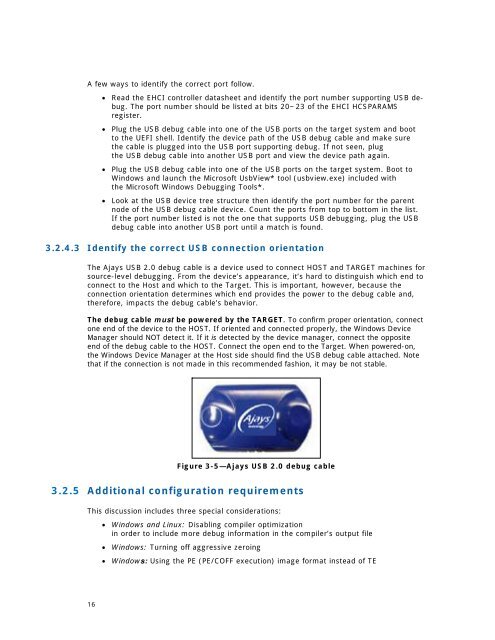
The Ajays USB 2.0 debug cable is a device used to connect HOST and TARGET machines for<br />
source-level debugging. From the device’s appearance, it’s hard to distinguish which end to<br />
connect to the Host and which to the Target. This is important, however, because the<br />
connection orientation determines which end provides the power to the debug cable and,<br />
therefore, impacts the debug cable’s behavior.<br />
The debug cable must be powered by the TARGET. To confirm proper orientation, connect<br />
one end of the device to the HOST. If oriented and connected properly, the Windows Device<br />
Manager should NOT detect it. If it is detected by the device manager, connect the opposite<br />
end of the debug cable to the HOST. Connect the open end to the Target. When powered-on,<br />
the Windows Device Manager at the Host side should find the USB debug cable attached. Note<br />
that if the connection is not made in this recommended fashion, it may be not stable.<br />
Figure 3-5—Ajays USB 2.0 debug cable<br />
3.2.5 Additional configuration requirements<br />
This discussion includes three special considerations:<br />
Windows and Linux: Disabling compiler optimization<br />
in order to include more debug information in the compiler’s output file<br />
Windows: Turning off aggressive zeroing<br />
Windows: Using the PE (PE/COFF execution) image format instead of TE<br />
16