
You also want an ePaper? Increase the reach of your titles
YUMPU automatically turns print PDFs into web optimized ePapers that Google loves.
<strong>9600</strong> <strong>HWG</strong> Water Heater Page 3<br />
SECTION 1.<br />
Introduction & Unpacking<br />
1A. Special Installation Considerations<br />
BEFORE YOU BEGIN:<br />
It is important for you to take a few minutes to<br />
review this Installation and Operating Instructions<br />
manual before you begin installation. This will make<br />
installing and operating the unit easier and faster.<br />
Direct vent-sealed combustion.<br />
The <strong>9600</strong> <strong>HWG</strong> Water Heater does not and<br />
should not take combustion air from inside the<br />
building. All of the air is drawn in from the outdoors<br />
through a 3-inch diameter plastic pipe. 3" PVC, ABS<br />
or CPVC pipe is used for air intake and exhaust<br />
venting. (PVC not permitted on <strong>HWG</strong>-M2-250<br />
exhaust)<br />
No chimney......flue......or draft inducer required.<br />
Because this is a sealed combustion, forced draft unit,<br />
it does not require, and must not be connected to a<br />
chimney, existing venting system, or draft inducer.<br />
CAUTION<br />
Connection of this vent to a chimney, existing<br />
venting system, or draft inducer will result in<br />
poor and possibly dangerous operation.<br />
The supplied vent terminations are designed to<br />
be installed through the nearest outside wall (see<br />
Sections 2C and 2D).<br />
The <strong>9600</strong> <strong>HWG</strong> Water Heater is protected<br />
against over pressurization. A 150 PSI pressure relief<br />
valve is fitted to the unit. It is installed in the<br />
dedicated fitting on the top of the water heater.<br />
IMPORTANT: The inlet gas pressure to the<br />
appliance must not exceed 13" WC.<br />
A high quality circulator is built into the <strong>9600</strong><br />
<strong>HWG</strong> Water Heater and will provide sufficient head<br />
pressure and volume to circulate water to the storage<br />
tank(s) (see Table 3).<br />
All installations must be made in accordance<br />
with the: 1) American National Standard Z223.1-<br />
Latest Edition “National Fuel Gas Code” and with the<br />
requirement of the local utility or other authorities<br />
having jurisdiction, or; 2) Can-CGA B149 installation<br />
code and / or local installation codes.<br />
Such applicable requirements take precedence<br />
over the general instructions contained herein.<br />
All electrical wiring is to be done in accordance<br />
with local codes, or in the absence of local codes,<br />
with: 1) the National Electrical Code ANSI/NFPA<br />
No. 70-latest Edition, or; 2) CSA standard C22.1<br />
“Canadian Electrical Code - Pt 1. This appliance<br />
must be electrically grounded in accordance with<br />
these codes.<br />
1B. Checklist of Materials Installer<br />
Must Provide<br />
1. The following are acceptable materials for intake<br />
and exhaust vents:<br />
a) 3" or 4" PVC sched. 40 pipe per ASTM D-<br />
1785 standard. (Not permitted on <strong>HWG</strong>-<br />
250 exhaust).<br />
b) 3" or 4" PVC DWV pipe per ASTM D-<br />
2665 standard. (Not permitted on <strong>HWG</strong>-<br />
250 exhaust).<br />
c) 3" or 4" ABS-DWV pipe per ASTM D-<br />
2661 or ASTM F-628 Standard.<br />
d) 3" or 4" CPVC schedule 40 pipe per ASTM<br />
F441 standard.<br />
e) The solvent cement for pipe joints is to<br />
comply with the following standards:<br />
1). PVC pipe D2564<br />
ABS pipe D2235<br />
CPVC pipe F493<br />
2). CSA listed solvent for a-d<br />
2. Electrical connection to a 120VAC/15Amp<br />
service.<br />
3. Gas connection that will provide 250 cubic feet/<br />
hour at 4 to 13 inch water gauge pressure.<br />
4. Condensate drainage: a floor drain is preferred -<br />
a condensate pump may be used.<br />
5. Miscellaneous copper fittings and bronze valves<br />
will be required to complete the piping system.<br />
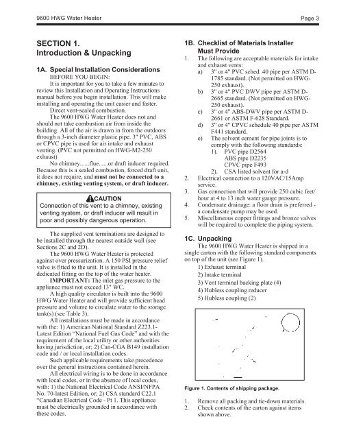
1C. Unpacking<br />
The <strong>9600</strong> <strong>HWG</strong> Water Heater is shipped in a<br />
single carton with the following standard components<br />
on top of the unit (see Figure 1).<br />
1) Exhaust terminal<br />
2) Intake terminal<br />
3) Vent terminal backing plate (4)<br />
4) Hubless coupling reducer<br />
5) Hubless coupling (2)<br />
Figure 1. Contents of shipping package.<br />
1. Remove all packing and tie-down materials.<br />
2. Check contents of the carton against items<br />
shown above.