
Create successful ePaper yourself
Turn your PDF publications into a flip-book with our unique Google optimized e-Paper software.
Page 4 LAARS HEATING SYSTEMS<br />
SECTION 2.<br />
Locating and Clearances<br />
2A. Locating the <strong>9600</strong> <strong>HWG</strong><br />
The appliance should be located in an area where<br />
leakage of any connections will not result in damage<br />
to the area adjacent to the appliance or to lower floors<br />
of the structure.<br />
When such a location is not available, it is<br />
recommended that a suitable drain pan, adequately<br />
drained, be installed under the appliance.<br />
The unit is design certified by AGA / CGA for<br />
installation on combustible flooring; in basements; in<br />
closets, utility rooms or alcoves. It must not be<br />
installed on carpeting.<br />
The location for the unit should be chosen with<br />
regard to the vent pipe lengths, external plumbing,<br />
ventilation of operating components and accessibility<br />
for service and cleaning.<br />
If there is potential for snow accumulation in your<br />
area, both the vent terminals should be installed at an<br />
appropriate level above grade (see Figures 2 and 3).<br />
The following dimensions and requirements<br />
should be met when choosing the location for the unit<br />
(see Table 1):<br />
Minimum Recommended<br />
Clearances Clearance for<br />
From Accessibility<br />
Combustible and Venting<br />
Construction<br />
BOTH AGA CGA<br />
Left Side 1" 6" 48"<br />
Right Side (Controls) 1" 12" 24"<br />
Top 1" 14" 24"<br />
Back 1" 9" 24"<br />
Front 1" 24" 48"<br />
Vent 0"<br />
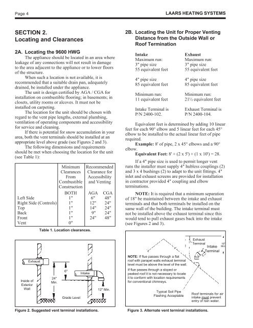
Inside of<br />
Exterior<br />
Wall<br />
Exhaust<br />
Table 1. Location clearances.<br />
24"<br />
Min.<br />
Figure 2. Suggested vent terminal installations.<br />
6"<br />
Grade Level<br />
Intake<br />
12" Min.<br />
2B. Locating the Unit for Proper Venting<br />
Distance from the Outside Wall or<br />
Roof Termination<br />
Intake Exhaust<br />
Maximum run: Maximum run:<br />
3" pipe size 3" pipe size<br />
55 equivalent feet 55 equivalent feet<br />
4" pipe size 4" pipe size<br />
85 equivalent feet 85 equivalent feet<br />
Minimum run: Minimum run:<br />
11 equivalent feet 21½ equivalent feet<br />
Intake Terminal is Exhaust Terminal is<br />
P/N 2400-102. P/N 2400-104.<br />
Equivalent feet is determined by adding 10 linear<br />
feet for each 90° elbow and 5 linear feet for each 45°<br />
elbow to be installed to the actual linear feet of pipe<br />
required.<br />
Example: 8' of pipe, 2 x 45° elbows and a 90°<br />
elbow.<br />
Equivalent Feet: 8' + (2 x 5') + (1 x 10') = 28.<br />
If a 4" pipe size is used to permit longer vent<br />
runs the installer must supply 4" hubless couplings (2)<br />
and 3 x 4 bushings (2) to adapt to the unit fittings. 4"<br />
inlet and exhaust screens are provided for installation<br />
in contractor provided 4" coupling and elbow<br />
terminations.<br />
NOTE: It is required that a minimum separation<br />
of 18" be maintained between the intake and exhaust<br />
terminals and that both terminals be installed on the<br />
same wall of the building. The intake terminal must<br />
not be installed above the exhaust terminal since this<br />
would tend to pull exhaust gases back into the intake<br />
(see Figures 2 and 3).<br />
NOTE: If flue passes through a flat<br />
roof with parapet walls exhaust terminal<br />
level must be above the level of the wall.<br />
If flue passes through a sloped or<br />
peaked roof it is not necessary to locate<br />
it to conform with location requirements<br />
for conventional chimneys.<br />
Typical Soil Pipe<br />
Flashing Acceptable<br />
Exhaust<br />
Terminal Intake<br />
Terminal<br />
Figure 3. Alternate vent terminal installations.<br />
18"<br />
Min.<br />
Roof terminals for air<br />
intake must prevent<br />
entry of rain water.