
You also want an ePaper? Increase the reach of your titles
YUMPU automatically turns print PDFs into web optimized ePapers that Google loves.
<strong>9600</strong> <strong>HWG</strong> Water Heater Page 5<br />
2C. Locating Vent Openings on Outside Wall<br />
1. Exhaust terminal location.<br />
The exhaust terminal fitting requires a 4" (10cm)<br />
diameter hole through the outside wall. The<br />
center line of this opening must be at least 16"<br />
(41cm) above grade and at least 14" (35.6cm)<br />
from any other building opening such as doors,<br />
windows, etc.<br />
Vent opening should be well away from<br />
shrubbery or other obstructions that would block<br />
or restrict the exhaust.<br />
Whenever possible, locations under windows or<br />
near doors should be avoided. Steaming at the<br />
flue terminal is a normal occurrence. This should<br />
be considered when deciding flue terminal<br />
position.<br />
2. Intake terminal location.<br />
The intake terminal requires a separate 4" (10cm)<br />
diameter hole to install the intake fitting. The<br />
center line of the hole should be at least 16"<br />
(41cm) above grade outdoors and 18" (46cm)<br />
away from the exhaust outlet. The intake should<br />
never be located above the exhaust terminal.<br />
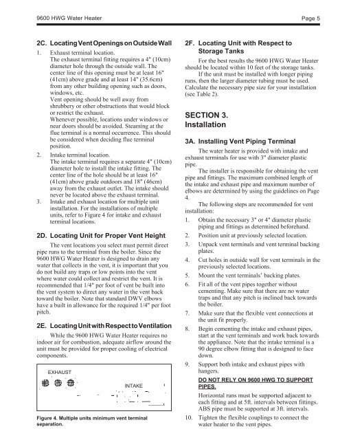
3. Intake and exhaust location for multiple unit<br />
installation. For the installations of multiple<br />
units, refer to Figure 4 for intake and exhaust<br />
terminal locations.<br />
2D. Locating Unit for Proper Vent Height<br />
The vent locations you select must permit direct<br />
pipe runs to the terminal from the boiler. Since the<br />
<strong>9600</strong> <strong>HWG</strong> Water Heater is designed to drain any<br />
water that collects in the vent, it is important that you<br />
do not build any traps or low points into the vent<br />
where water could collect and restrict the vent. It is<br />
recommended that 1/4" per foot of vent be built into<br />
the vent system to direct any water in the vent back<br />
toward the boiler. Note that standard DWV elbows<br />
have a built in allowance for the required 1/4" per foot<br />
pitch.<br />
2E. Locating Unit with Respect to Ventilation<br />
While the <strong>9600</strong> <strong>HWG</strong> Water Heater requires no<br />
indoor air for combustion, adequate airflow around the<br />
unit must be provided for proper cooling of electrical<br />
components.<br />
EXHAUST<br />
INTAKE<br />
Figure 4. Multiple units minimum vent terminal<br />
separation.<br />
2F. Locating Unit with Respect to<br />
Storage Tanks<br />
For the best results the <strong>9600</strong> <strong>HWG</strong> Water Heater<br />
should be located within 10 feet of the storage tanks.<br />
If the unit must be installed with longer piping<br />
runs, then the larger diameter tubing must be used.<br />
Calculate the necessary pipe size for your installation<br />
(see Table 2).<br />
SECTION 3.<br />
Installation<br />
3A. Installing Vent Piping Terminal<br />
The water heater is provided with intake and<br />
exhaust terminals for use with 3" diameter plastic<br />
pipe.<br />
The installer is responsible for obtaining the vent<br />
pipe and fittings. The maximum combined length of<br />
the intake and exhaust pipe and maximum number of<br />
elbows are determined by using the guidelines on Page<br />
4.<br />
The following steps are recommended for vent<br />
installation:<br />
1. Obtain the necessary 3" or 4" diameter plastic<br />
piping and fittings as determined beforehand.<br />
2. Position unit at previously selected location.<br />
3. Unpack vent terminals and vent terminal backing<br />
plates.<br />
4. Cut holes in outside wall for vent terminals in the<br />
previously selected locations.<br />
5. Mount the vent terminals’ backing plates.<br />
6. Fit all of the vent pipes together without<br />
cementing. Make sure that there are no water<br />
traps and that any pitch is inclined back towards<br />
the boiler.<br />
7. Make sure that the flexible vent connections at<br />
the unit fit properly.<br />
8. Begin cementing the intake and exhaust pipes,<br />
start at the vent terminals and work back towards<br />
the appliance. Note that the intake terminal is a<br />
90 degree elbow fitting that is designed to face<br />
down.<br />
9. Support both intake and exhaust pipes with<br />
hangers.<br />
DO NOT RELY ON <strong>9600</strong> <strong>HWG</strong> TO SUPPORT<br />
PIPES.<br />
Horizontal runs must be supported adjacent to<br />
each fitting and at 5ft. intervals between fittings.<br />
ABS pipe must be supported at 3ft. intervals.<br />
10. Tighten the flexible couplings to connect the<br />
water heater to the vent pipes.