Q-4⢠Installation Manual - Viking Access
Q-4⢠Installation Manual - Viking Access
Q-4⢠Installation Manual - Viking Access

Create successful ePaper yourself
Turn your PDF publications into a flip-book with our unique Google optimized e-Paper software.
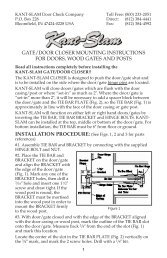
PLAN OF INSTALLATION – CONCRETE PADS<br />
Track<br />
Gate<br />
10"<br />
2"<br />
4"<br />
Minimum<br />
Install a<br />
Positive Stop<br />
at Both Ends 24"<br />
of the Track<br />
Track Concrete Pad<br />
Operator Chassis<br />
Gate Operator Concrete Pad<br />
28"<br />
Drill for a 1/2" x 3-1/2"<br />
Red Head Anchor<br />
(4) Places<br />
5.5"<br />
13"<br />
Center of<br />
Drive Chain<br />
Recommended<br />
Area for<br />
Conduit(s)<br />
5"<br />
18"<br />
6"<br />
11.75"/13.75"/15.75"<br />
4"<br />
Minimum<br />
Conduit Location<br />
24"<br />
See Note 1<br />
Below<br />
Grade Level<br />
See Note 2<br />
Track Concrete Pad<br />
Gate Operator Concrete Pad<br />
1. Follow the local building code to determine the required depth of the concrete pad.<br />
2. Pad measurements recommended by <strong>Viking</strong> <strong>Access</strong> Systems are at lease 24” long,<br />
18” wide and 24” deep to ensure the stable operation of the operator, and a<br />
minimum of 4” above level grade to avoid any flooding of the machinery.<br />
3. The path of the track must be 10” wide and at least 6” deep to support the<br />
weight of the gate. Please consult the local building code for verification and<br />
further details.<br />
4. Provide a sufficient number of conduit pathways for all low power accessories<br />
such as loop detector leads, maglock, non-contact sensors, contact sensors, safety<br />
and other commands. Also provide conduit for the power supply (either 110 or<br />
220 VAC). Extend the conduit the recommended height of 1” above the level of<br />
the concrete pad. Install all conduit in the shaded area shown above.<br />
TECHNICAL SUPPORT 1 800 908 0884 11