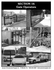
Q-4⢠Installation Manual - Viking Access
Q-4⢠Installation Manual - Viking Access
Q-4⢠Installation Manual - Viking Access

You also want an ePaper? Increase the reach of your titles
YUMPU automatically turns print PDFs into web optimized ePapers that Google loves.
TROUBLESHOOTING<br />
Gate does not open or close<br />
Check all motor connections to<br />
be fully engaged. Refer to page<br />
15.<br />
Check that the UL command<br />
(photo beam and/or edge<br />
sensor) is not active. Refer to<br />
page 6, 7 and 23.<br />
Ensure that you external<br />
accessories are working<br />
properly<br />
Automatic close does not function<br />
Check that the trim pot of the<br />
hold open timer is set to the<br />
proper time delay. Refer to<br />
page 28.<br />
Note: Hold open timer closes<br />
the gate automatically once the<br />
gate reaches the limit open.<br />
The time delay to close is set<br />
by the trim pot.<br />
To turn this system off turn the<br />
trim pot all the way clockwise<br />
Gate opens in the opposite desired direction<br />
Verify your motor cable is<br />
connected to the proper<br />
connector. Refer to page 15<br />
and 16.<br />
Check that limit switches are<br />
connected to the common and<br />
the normally close position<br />
refer to page 16.<br />
Check that the vehicular loop<br />
detectors are working properly.<br />
Refer to page 20, 21 and 23.<br />
Check that all motor cable<br />
connections, junctions and<br />
extensions are properly<br />
connected and color-coded.<br />
Refer to 15.<br />
Check that the stop command<br />
is not active. Refer to page 8<br />
and 27.<br />
Check that the radio command<br />
is not active. Refer to page 24.<br />
• Make sure gate is fully open<br />
• Check photobeam path for<br />
obstruction<br />
• Check photobeam power<br />
• Check loop detectors for<br />
proper function<br />
On a Master/Slave installation, one gate runs in the opposite direction<br />
Check the motor and limit<br />
switch wiring. Refer to page 15<br />
and 16.<br />
Verify you are using shielded<br />
cables and that the shield is<br />
connected to the chassis ground<br />
at both ends, the master side<br />
and at the slave side.<br />
Verify that one unit is<br />
connected as open-left and one<br />
unit is connected as openright.<br />
Refer to page 15.<br />
Verify the interconnecting<br />
wiring color codes match on<br />
both the master and slave<br />
boards. Refer to page 19.<br />
32 TECHNICAL SUPPORT 1 800 908 0884<br />
29