

Compact PIFA for 2.4 5 GHz dual ISM-band applications ...
Compact PIFA for 2.4 5 GHz dual ISM-band applications ...
Compact PIFA for 2.4 5 GHz dual ISM-band applications ...

You also want an ePaper? Increase the reach of your titles
YUMPU automatically turns print PDFs into web optimized ePapers that Google loves.
<strong>Compact</strong> <strong>PIFA</strong> <strong>for</strong> <strong>2.4</strong>=5 <strong>GHz</strong> <strong>dual</strong> <strong>ISM</strong>-<strong>band</strong><br />
<strong>applications</strong><br />
J.-I. Moon, D.-U. Sim and S.-O. Park<br />
A compact and novel modified planar inverted-F antenna (<strong>PIFA</strong>) <strong>for</strong><br />
<strong>dual</strong> <strong>ISM</strong>-<strong>band</strong> application is proposed. The proposed antenna, including<br />
a small ground plane, occupies a volume of 20 23.7 0.8 mm 3<br />
(FR-4). The impedance <strong>band</strong>width with 10 dB return loss is about<br />
150 MHz (2380–2530 MHz) <strong>for</strong> <strong>2.4</strong> <strong>GHz</strong> <strong>band</strong> and 1450 MHz (5130–<br />
6580 MHz) <strong>for</strong> 5 <strong>GHz</strong> <strong>band</strong>. The measured radiation patterns are<br />
approximately omnidirectional and yield a gain of 1.0 dBi at<br />
2440 MHz and 3.98 dBi at 5600 MHz, respectively.<br />
Introduction: As portable wireless devices become smaller and have<br />
the design requirements <strong>for</strong> multi<strong>band</strong> antennas, the antenna volume<br />
including a ground substrate should be reduced. In particular, the<br />
rapid development of the <strong>applications</strong> <strong>for</strong> wireless local area network<br />
(WLAN) has promoted the novel antenna design mounted on a small<br />
ground plane <strong>for</strong> <strong>dual</strong> <strong>ISM</strong> <strong>band</strong>, namely <strong>2.4</strong> <strong>GHz</strong> (2400–2483 MHz)<br />
and 5 <strong>GHz</strong> (5150–5350=5725–5875 MHz), respectively. However, in<br />
many previous papers [1, 2], the antenna per<strong>for</strong>mances are influenced<br />
by the size of ground plane. Since the ground plane becomes a<br />
primary source of radiation, the smaller ground strongly influences<br />
small antenna properties. There<strong>for</strong>e, when these antennas have a small<br />
ground plane to apply to the practical <strong>applications</strong>, the per<strong>for</strong>mances<br />
such as return loss, <strong>band</strong>width and radiation gain at<br />
the frequency of interest are typically reduced [3]. InthisLetter,a<br />
compact <strong>PIFA</strong> model mounted on a small ground plane is proposed<br />
and how <strong>band</strong>s can be tuned is described.<br />
Antenna design: Fig. 1 shows the geometry of the proposed antenna<br />
with the combination of the modified inverted-F patch and the<br />
inverted L-shaped stub. The geometrical parameters of the length<br />
and width of strip lines are optimised in an attempt to achieve design<br />
goals at both the frequency <strong>band</strong>s of interest. For achieving the<br />
resonant mode at <strong>2.4</strong> <strong>GHz</strong> <strong>band</strong>, the strip line starting from<br />
the feeding point (point A) to the end point (point C) ischosento<br />
be 31 mm corresponding to about a quarter of one wavelength. In<br />
addition, to match the input impedance at <strong>2.4</strong> <strong>GHz</strong> frequency <strong>band</strong><br />
and contribute the radiating mode, the strip line (point B–point D) is<br />
connected with the ground plane. The loop shape of the strip line<br />
starting from point A to point D is a length of 24 mm. It is selected to<br />
give a resonant frequency in the 5 <strong>GHz</strong> <strong>band</strong>. Both the z-directed<br />
inverted L-shaped stub (height 6 mm, point E) and the ground plane,<br />
which is implemented on the back side of the substrate, also play an<br />
important role in enhancing the impedance <strong>band</strong>width and the radiation<br />
gain at both frequency <strong>band</strong>s.<br />
z<br />
y<br />
x<br />
1.8<br />
23.7<br />
15.5<br />
C<br />
3 2<br />
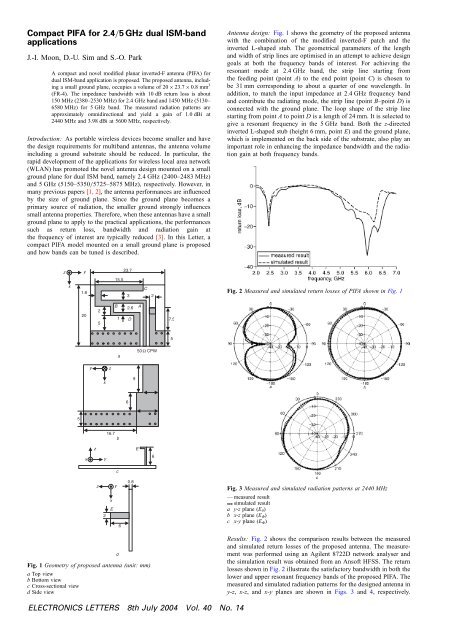
Fig. 2 Measured and simulated return losses of <strong>PIFA</strong> shown in Fig. 1<br />
20<br />
2<br />
5<br />
B<br />
1 D<br />
2.6 A<br />
7.5<br />
5<br />
a<br />
50 W CPW<br />
y<br />
z<br />
x<br />
9<br />
6<br />
5<br />
16.7<br />
b<br />
z<br />
E<br />
x<br />
y<br />
6<br />
c<br />
z<br />
y<br />
0.8<br />
Fig. 3 Measured and simulated radiation patterns at 2440 MHz<br />
2<br />
x<br />
E<br />
6<br />
— measured result<br />
simulated result<br />
a y-z plane (E y )<br />
b x-z plane (E F )<br />
c x-y plane (E F )<br />
Fig. 1 Geometry of proposed antenna (unit: mm)<br />
a Top view<br />
b Bottom view<br />
c Cross-sectional view<br />
d Side view<br />
d<br />
Results: Fig. 2 shows the comparison results between the measured<br />
and simulated return losses of the proposed antenna. The measurement<br />
was per<strong>for</strong>med using an Agilent 8722D network analyser and<br />
the simulation result was obtained from an Ansoft HFSS. The return<br />
losses shown in Fig. 2 illustrate the satisfactory <strong>band</strong>width in both the<br />
lower and upper resonant frequency <strong>band</strong>s of the proposed <strong>PIFA</strong>. The<br />
measured and simulated radiation patterns <strong>for</strong> the designed antenna in<br />
y-z, x-z, andx-y planes are shown in Figs. 3 and 4, respectively.<br />
ELECTRONICS LETTERS 8th July 2004 Vol. 40 No. 14
As shown in Figs. 3 and 4, the radiation patterns are omnidirectional<br />
and very similar to those of the y-directed dipole antenna. The<br />
measured and simulated results agree well with each other at both<br />
frequencies. The maximum measured andsimulatedradiationgainare<br />
1.0 and 1.51 dBi at <strong>2.4</strong>4 <strong>GHz</strong> and 3.98 and 3.6 dBi at 5.6 <strong>GHz</strong>,<br />
respectively.<br />
Conclusions: A compact and novel planar inverted-F antenna (<strong>PIFA</strong>)<br />
has been proposed and implemented. The proposed antenna exhibits<br />
good impedance <strong>band</strong>width as well as radiation per<strong>for</strong>mance despite<br />
the miniaturised volume of 20 23.7 0.8 mm (FR-4). The obtained<br />
per<strong>for</strong>mance of this antenna shows an attractive feature <strong>for</strong> <strong>2.4</strong>=5 <strong>GHz</strong><br />
<strong>dual</strong> <strong>ISM</strong>-<strong>band</strong> <strong>applications</strong>.<br />
Acknowledgment: This work was supported by the National Research<br />
Laboratory (NRL) of the Ministry of Science and Technology, Korea,<br />
under contract no. M1-0203-0015.<br />
# IEE 2004 6 May 2004<br />
Electronics Letters online no: 20045286<br />
doi: 10.1049/el:20045286<br />
J.-I. Moon, D.-U. Sim and S.-O. Park (School of Engineering,<br />
In<strong>for</strong>mation and Communications University, Daejeon, Korea)<br />
E-mail: jungick@icu.ac.kr<br />
References<br />
1 Lin, C.-C., Lee, G.-Y., and Wong, K.-L.: ‘Surface-mount <strong>dual</strong>-loop<br />
antenna <strong>for</strong> <strong>2.4</strong>=5 <strong>GHz</strong> WLAN operation’, Electron. Lett., 2003, 39,<br />
(18), pp. 1302–1304<br />
2 Moon, J.-I., and Park, S.-O.: ‘Small chip antenna <strong>for</strong> <strong>2.4</strong>=5.8-<strong>GHz</strong> <strong>dual</strong><br />
<strong>ISM</strong>-<strong>band</strong> <strong>applications</strong>’, IEEE Antenna Wirel. Propag. Lett., 2003, 2,<br />
(21), pp. 313–315<br />
3 Huynh, M.-C., and Stutzman, W.: ‘Ground plane effects on planar<br />
inverted-F antenna(<strong>PIFA</strong>) per<strong>for</strong>mance’, IEE Proc., Microw. Antennas<br />
Propag., 2003, 150, (4), pp. 209–213<br />
Fig. 4 Measured and simulated radiation patterns at 5600 MHz<br />
— measured result<br />
simulated result<br />
a y-z plane (E y )<br />
b x-z plane (E F )<br />
c x-y plane (E F )<br />
ELECTRONICS LETTERS 8th July 2004 Vol. 40 No. 14


