HSL-WI3 - Sea-Seg.com
HSL-WI3 - Sea-Seg.com
HSL-WI3 - Sea-Seg.com

You also want an ePaper? Increase the reach of your titles
YUMPU automatically turns print PDFs into web optimized ePapers that Google loves.
SYSTEMS<br />
Controls for the Metal Container Industry<br />
<strong>HSL</strong>-<strong>WI3</strong><br />
STANDUN BODYMAKER<br />
HIGH SPEED CONTROL PACKAGE<br />
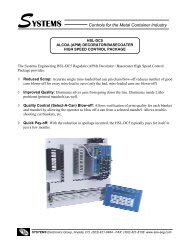
The Systems Engineering <strong>HSL</strong>-<strong>WI3</strong> Standun Bodymaker High Speed Control Package is an electronic<br />
upgrade which provides:<br />
◊<br />
◊<br />
◊<br />
◊<br />
Reduced Tooling Damage: by accurately detecting short can/tear-offs and immediately deactivating<br />
the clutch and cupfeed to prevent feeding additional cups.<br />
Repeatable Air Strip Control: to prevent air stripping and blow-out problems and thus reduce<br />
the occurrence of short cans or tear-offs.<br />
Accurate Clutch Control: Incorporates BDC brake wear <strong>com</strong>pensation algorithm to stop press at<br />
BDC regardless of actual brake response.<br />
High Speed: Package operates at speeds in excess of 500 Cans Per Minute.<br />
SYSTEMS Electronics Group, Arvada, CO (303) 421-0484 - FAX: (303) 421-8108 www.sea-seg.<strong>com</strong>
Features<br />
• Performs high speed control functions of Standun Bodymaker to speeds in excess of 500 Cans Per Minute<br />
(machine mechanically permitting). This includes clutch control, cupfeed control, air strip control, as well as<br />
die protection (short can detection).<br />
• Performs the following control functions:<br />
• Rapid response control of clutch/brake system for emergency stops (die protection) as well as precise<br />
BDC stops. Note: The clutch solenoid outputs of the <strong>HSL</strong>-<strong>WI3</strong> are not intended as safety contacts<br />
for the bodymaker clutch and must not be the only interrupt to the clutch solenoids.<br />
• Accurate short can detection to a resolution of ¼” can length.<br />
• Highly repeatable air strip control to reduce can stripping and blow-out problems.<br />
• Reliable, timed cupfeed control to insure proper cup loading and protection from miss-loads.<br />
• Brake wear <strong>com</strong>pensation (Auto BDC timing programming) algorithm to stop press at BDC regardless of<br />
brake response.<br />
• Brake response determination allows displaying of actual brake response (in degrees).<br />
• Brake response alarm to indicate when brake stopping response (in degrees) has exceeded user preset<br />
limit.<br />
• Trimmer speed reference (0-10volt analog output) provides reference to trimmer proportional to speed of<br />
bodymaker (user scalable).<br />
• Alarm detection: short can detection, die sensor fail alarm, timing signal fail detection, clutch output failure<br />
detection, no ram motion alarm, resolver failure detection, and brake response too long.<br />
• Data Acquisition: Total number of good cans produced and total number of short can faults (for both current<br />
and last shift).<br />
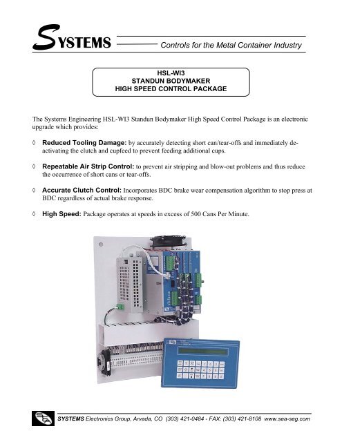
General Description<br />
The <strong>HSL</strong>-<strong>WI3</strong> Standun Bodymaker high speed logic<br />
module is an electronic upgrade for the Standun Bodymaker<br />
which performs the high speed control functions of<br />
the bodymaker including: rapid response clutch/brake<br />
control, accurate short can detection, reliable cupfeed and<br />
precise air strip control. In addition, the package provides<br />
a brake wear <strong>com</strong>pensation feature which automatically<br />
adjusts the BDC timing signal to stop the press at BDC<br />
regardless of brake stopping response.<br />
Alarm detection is provided including: short can detection,<br />
die sensor failure detection, timing signal failure,<br />
brake response too long and more. Data collection includes:<br />
Total good can count and total short can faults<br />
count (both for the current shift and last previous (last)<br />
shift). In addition, the package also provides a trimmer<br />
speed reference output which is proportional to the<br />
bodymaker speed.<br />
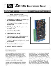
The package is not a dedicated “black box”, but instead is<br />
implemented using the high performance Systems M4500<br />
PLC/PLS module which allows easy customization by<br />
either SEA or the end user. The M4500 module is programmed<br />
using the DOS-based SYSdev programming<br />
package which allows the module to be programmed in<br />
any <strong>com</strong>bination of Ladder logic or High-level (subset of<br />
“C”), as well as perform on-line monitoring and troubleshooting.<br />
The M4500 incorporates a built-in PLS which<br />
interfaces directly with the machine mounted resolver and<br />
provides all machine timing, eliminating the need for an<br />
external PLS.<br />
Clutch / Brake Control<br />
The clutch/brake solenoids of the Bodymaker are activated<br />
by the <strong>HSL</strong>-<strong>WI3</strong> through the electro-mechanical<br />
two hand safety control circuitry provided externally by<br />
the user. The fast 0.5millisecond throughput of the <strong>HSL</strong>-<br />
<strong>WI3</strong> along with the fact that the PLS is fully integrated in<br />
the module, allows extremely fast and repeatable declutching<br />
and braking response to be achieved. Normally<br />
the clutch is controlled via inputs to the <strong>HSL</strong>-<strong>WI3</strong> that are<br />
mapped from outputs on the host PLC. However, detection<br />
of any of the alarms (short can, die sensor failure,<br />
etc.) results in an immediate de-clutch of the solenoids.<br />
SYSTEMS Electronics Group, Arvada, CO (303) 421-0484 - FAX: (303) 421-8108 www.sea-seg.<strong>com</strong>
Air Strip Control<br />
The <strong>HSL</strong>-<strong>WI3</strong> provides a repeatability of 0.5 milliseconds<br />
for the air strip control thus reducing can stripping<br />
and blow-out problems. Both an “Air Strip (Low)” and<br />
“Air Strip (High)” timing signal are provided to activate<br />
the air strip when running in the low and high speeds respectively.<br />
The air strip is enabled when the cupfeed is<br />
opened.<br />
Brake Wear Compensation<br />
The <strong>HSL</strong>-<strong>WI3</strong> incorporates a brake wear <strong>com</strong>pensation or<br />
automatic BDC timing feature which stops the press at<br />
BDC regardless of the actual braking response of the<br />
clutch/brake. The stopping <strong>com</strong>pensation is ac<strong>com</strong>plished<br />
by automatically adjusting the BDC timing signal based<br />
on the previous stop. Any overrun is detected and a new<br />
BDC timing signal is <strong>com</strong>puted such that the machine<br />
will stop at the desired location on the next stop. Two<br />
BDC signals are provided: one for low speed and one for<br />
high speed. Both incorporate the brake wear <strong>com</strong>pensation<br />
feature. The appropriate BDC timing signal (low or<br />
high) is adjusted based on the speed of the machine when<br />
the BDC stop was initiated.<br />
In addition to the brake wear <strong>com</strong>pensation, the <strong>HSL</strong>-<strong>WI3</strong><br />
also calculates the actual brake response (in degrees).<br />
This is the number of degrees from where the clutch was<br />
de-activated (BDC timing location) to where the crankshaft<br />
actually ended up stopping. This can then be displayed<br />
by the operator or maintenance personnel to determine<br />
the condition of the brake.<br />
Short Can Detection<br />
The “Short Can Check” timing signal, along with the existing<br />
machine mounted short can sensor, is used to verify<br />
the entire length of the can. The short can sensor must see<br />
can the entire time the “Short Can Check” timing signal is<br />
“on”. If the can is short (tear-off) or any void is detected,<br />
the Short Can alarm is generated. The clutch is immediately<br />
de-activated as well as the cupfeed solenoid. The<br />
resolution of the short can check is 0.5 milliseconds. At a<br />
machine speed of 250CPM, this translates to approximately<br />
¼” resolution in can length.<br />
Alarm Detection<br />
In addition to the Short Can alarm, the module detects the<br />
following alarms: Die Sensor Failure, Timing Signal<br />
Fail, Clutch Output Failure, No Ram Motion Detected,<br />
Resolver Failure, and Brake Response Too Long. The Die<br />
Sensor Fail alarm occurs if the “short can” sensor fails<br />
“on”. The Timing Signal Fail occurs when any of the<br />
timing signals generated in the PLS section fail to<br />
Alarm Detection (cont’d)<br />
change state periodically while the machine is running.<br />
The Clutch Output Fail alarm occurs if either clutch output<br />
fails “on” or “off”. No Ram Motion occurs if no motion<br />
is detected after the clutch is activated. The Resolver<br />
Failure alarm occurs if motion is detected after the clutch<br />
is de-activated. The above alarms immediately de-activate<br />
the clutch when any one occurs with the respective alarm<br />
message displayed on the <strong>HSL</strong>-<strong>WI3</strong>. These alarms are<br />
summed into one output that indicates to the host PLC<br />
that an alarm did occur.<br />
Data Collection<br />
The following data is collected for both the current shift<br />
and the previous (last) shift: Total number of good cans<br />
produced and total number of short can faults. This data<br />
can be viewed locally on the display of the <strong>HSL</strong>-<strong>WI3</strong> by<br />
the operator or production control personnel. This information<br />
is updated (“current” shift transferred to “last”<br />
shift) based on the change of state of a discrete input.<br />
This data can also be passed back to a host PLC via the<br />
optional S4516 Communications Board. For Modicon<br />
PLCs, the MODBUS protocol is used. For TI PLCs the<br />
S3000 network is used in conjunction with an S3016-505<br />
mounted in the TI rack. For A-B PLCs, an S4516-DF1 is<br />
used which implements the A-B DF1 protocol.<br />
<strong>HSL</strong>-<strong>WI3</strong> Keypad / Display<br />
The keypad / Display of the <strong>HSL</strong>-<strong>WI3</strong> is designed to<br />
mount in the door of the enclosure that the <strong>HSL</strong>-<strong>WI3</strong> subpanel<br />
is mounted in (maximum cable length of 8 feet).<br />
The keypad contains 24 keys consisting of data display<br />
<strong>com</strong>mands, setup <strong>com</strong>mands, and a numeric keypad. The<br />
display of the <strong>HSL</strong>-<strong>WI3</strong> is a 2-line by 40-character backlit<br />
LCD display which displays the selected data and<br />
setup menus. The keypad / display can be used by the<br />
operator or production control personnel to view the collected<br />
data and can be used by authorized personnel<br />
(passcode or key switch protected) to adjust the timing<br />
and all setup parameters.<br />
IMPORTANT SAFETY WARNING<br />
The <strong>HSL</strong>-<strong>WI3</strong> is intended as a high-speed logic gate to provide<br />
consistent and accurate clutch control. It is not designed<br />
as a redundant, dual-processor clutch brake safety<br />
module. The <strong>HSL</strong>-<strong>WI3</strong> must not be the only means of controlling<br />
the bodymaker clutch mechanism. Good design practice<br />
dictates the use of safety interlocks on any device that starts<br />
or stops automatically that can cause personnel injury to<br />
operating or maintenance personnel. The <strong>HSL</strong>-<strong>WI3</strong> must be<br />
used only in conjunction with industry approved safety interlock<br />
contacts, implemented in accordance with ANSI B11.1<br />
safety requirements, otherwise serious personnel injury may<br />
result.<br />
SYSTEMS Electronics Group, Arvada, CO (303) 421-0484 - FAX: (303) 421-8108 www.sea-seg.<strong>com</strong>
Specifications<br />
Power Requirements:<br />
Voltage: 100-240VAC, 50/60HZ<br />
Current: 0.5 Amps @ 115VAC<br />
0.25 Amps @ 230VAC<br />
Temperature Ranges:<br />
Operating: 0 to 55°C<br />
Storage: 0 to 70°C<br />
Resolver Interface:<br />
Resolver Type: Systems Electronics Group<br />
RSV34-MS1 or equivalent (also can be paralleled<br />
with existing resolver/PLS)<br />
Resolver Cable: Systems Electronics Group<br />
RSV-RSCBLE-XX<br />
Control Inputs:<br />
Voltage Range: 10-30VDC<br />
Input “On” Voltage (min): 10.0 volts<br />
Input “On” Voltage (max): 30.0 volts<br />
Input “Off” Voltage (max): 5.0 volts<br />
Input Current (max): 15 milliamps @ Vin=30V<br />
Optical Isolation: 1500 Vrms<br />
Outputs:<br />
Voltage Range: 10-30VDC<br />
Output “On” Voltage (min): VCC-2.00 volts<br />
Output “On” Voltage (max): VCC-0.25 volts<br />
Output “Off” Voltage (max): 1.5 volts<br />
Output “On” Current (max-cont): 0.5 Amps DC<br />
Output “On” Current (100msec): 3.0 Amps DC<br />
Optical Isolation: 1500 Vrms<br />
Ordering Information<br />
The <strong>HSL</strong>-<strong>WI3</strong> package is provided for back-panel mounting inside the user’s existing control cabinet. In addition, a NEMA<br />
12 enclosure can be purchased to house the <strong>HSL</strong>-<strong>WI3</strong> if the required space is not available in the existing user’s cabinet. The<br />
part number for the optional NEMA 12 enclosure is <strong>HSL</strong>-<strong>WI3</strong>-ENCL. The order number for the <strong>HSL</strong>-<strong>WI3</strong> is as follows:<br />
Part Number<br />
<strong>HSL</strong>-<strong>WI3</strong><br />
Description<br />
Standun Bodymaker high speed control package consisting of a prewired<br />
sub-panel (17” X 13” X 8”) for mounting in the existing user’s control<br />
cabinet including the following:<br />
1ea.<br />
1ea.<br />
1ea.<br />
1ea.<br />
1ea.<br />
1ea.<br />
M4500 PLC/PLS module (with required I/O boards)<br />
D4591 Display / Keypad<br />
<strong>HSL</strong>-<strong>WI3</strong> User’s Manual<br />
<strong>HSL</strong>-<strong>WI3</strong> Keypad Quick Reference Manual<br />
<strong>HSL</strong>-<strong>WI3</strong> Program Disk<br />
M4500 User’s Manual<br />
<strong>HSL</strong>-<strong>WI3</strong> Options (purchased separately)<br />
The following items can be purchased separately as required or desired:<br />
Part Number<br />
Description<br />
<strong>HSL</strong>-DSP<br />
Remote RPM/Position Display<br />
<strong>HSL</strong>-<strong>WI3</strong>-ENCL NEMA 12 enclosure for <strong>HSL</strong>-<strong>WI3</strong> ( 20” X 16” X 10”)<br />
RSV34-MS1<br />
Resolver (required if machine is not already equipped with resolver)<br />
RSV-RSCBLE-XX Resolver Cable<br />
S4516<br />
Communications Option Board (Modicon and TI PLCs)<br />
S4516-DF1<br />
Communications Option Board (A-B PLCs)<br />
SYSTEMS Electronics Group, Inc.<br />
Division of SYSTEMS Engineering Associates, Inc.<br />
14989 W. 69 th Ave., Arvada, CO 80007<br />
Telephone: (303) 421-0484 FAX: (303) 421-8108 www.sea-seg.<strong>com</strong>