HSL-WISVCUP Ragsdale Bodymaker Servo ... - Sea-Seg.com
HSL-WISVCUP Ragsdale Bodymaker Servo ... - Sea-Seg.com
HSL-WISVCUP Ragsdale Bodymaker Servo ... - Sea-Seg.com

You also want an ePaper? Increase the reach of your titles
YUMPU automatically turns print PDFs into web optimized ePapers that Google loves.
CONTENTS3. Tuning the <strong>Servo</strong> Loop 293.1 Description of PID <strong>Servo</strong> Loop 293.2 Proportional (P) Gain 303.3 Integral (I) Gain 313.4 Derivative (D) Gain 323.5 Tuning the <strong>Servo</strong> Motor with Machine Running 334. <strong>WISVCUP</strong> - Windows BasedSet-up Program Reference 354.1 General Description 364.2 The File Menu 374.2.1 The Set-Up Data File 384.2.2 Upload (save) Data 394.2.3 Download Program 404.2.4 Download (restore) Data 424.2.5 Print Report 434.3 The Edit Menu 444.3.1 Enable Offline Editing 444.3.2 Set-Up Comm Port 454.3.3 Edit Set-Up Passcode 464.4 The View Menu 474.4.1 Target Board Interface 494.4.2 View Online Data 494.4.3 View Offline Data 494.5 The <strong>Bodymaker</strong> Menu 504.5.1 Main Display Window 514.5.2 Set-Up Parameters Window 524.5.3 Machine Timing Window 544.5.4 Shift Data Window 574.5.5 I/O States Window 594.6 The <strong>Servo</strong> Cupfeed Menu 604.6.1 Set-Up Parameters Window 614.6.2 Tuning Window 624.6.3 Diagnostics Window 654.6.4 Acquire Data Signatures Window 67<strong>HSL</strong>-<strong>WISVCUP</strong> User’s ManualSYSTEMS Electronics Group- ii -
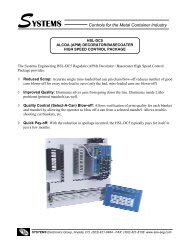
SECTION 1GENERAL DESCRIPTIONThis section describes the features of the <strong>HSL</strong>-<strong>WISVCUP</strong> <strong>Servo</strong>Cupfeed control package. This includes the functional description,alarms detected, interlocks between the control package and theexisting control system, etc.________________________________________________________1.1 FEATURES• Provides <strong>Servo</strong> motor driven positive cupfeed cam control forAPM Positive cupfeed cam upgrade.• Interfaces directly with cupfeed cam servo motor, machinemounted main crank resolver, and existing control system toaccurately cam cupfeed with main crank in all modes and allspeeds.• Immediate cupfeed cam stop at detection of short can or tear-offprotects valuable tooling by preventing the feeding of anadditional cup.• Completely automatic synchronization of cupfeed cam with maincrank shaft when clutch is engaged to reduce down-time andreduce operator manual interaction.• Optional high speed logic functions add-on performs additionalhigh speed control functions of <strong>Ragsdale</strong> <strong>Bodymaker</strong> includingcupfeed solenoid control, air strip control, as well as dieprotection (short can detection).• Alarm detection: cupfeed following fault, cupfeed servo motoro'temp, cupfeed motor amplifier fault.• Provided with Windows and DOS based set-up softwarepackages. This allows all user selectable parameters to be setusing easy to use menus as well as download the respectiveapplication programs and set-up data.• Based on the high performance M4510 PLC/PLS/Motion controlmodule. This allows easy trouble-shooting and user customizationusing SYSdev (DOS-based) programming package.<strong>HSL</strong>-<strong>WISVCUP</strong> User’s ManualSYSTEMS Electronics Group- 1 -
SECTION 1GENERAL DESRIPTION________________________________________________________1.2 FUNCTIONAL DESCRIPTIONThe <strong>HSL</strong>-<strong>WISVCUP</strong> <strong>Bodymaker</strong> servo cupfeed control package is anelectronic upgrade package used in conjunction with the <strong>Ragsdale</strong>servo positive cupfeed upgrade. It provides <strong>com</strong>plete motion controlof the servo cupfeed cam plus detection of the following alarms:cupfeed motor over temp, amplifier fault and cupfeed cam followingfault.The package interfaces directly to the machine mounted cupfeedservo motor, cupfeed timing sensor, main crank resolver, as well asthe host PLC via discrete DC I/O.The control system is not a dedicated "black box", but is insteadimplemented using the high performance SYSTEMS M4510PLC/PLS Motion control module. This allows easy customization byeither SEA or the end user. The M4510 module is programmed usingthe DOS-based SYSdev programming package. This allows themodule to be programmed in any <strong>com</strong>bination of Ladder or Highlevel(subset of "C"), as well as perform on-line monitoring andtrouble-shooting.________________________________________________________1.3 CUPFEED CAM SERVO MOTOR CONTROLThe cupfeed cam motor control is implemented with a high speed(0.5msec update) PID servo loop. The main crank position is used asthe reference for the servo loop with the cupfeed cam position used asthe feedback. Both main crank position and cupfeed cam positions aregenerated with resolvers to provide the highest degree of reliabilityand noise immunity. Both resolver format signals are converted todigital with a resolution of 12-bits (0-4095). The PID servo loop nullsthe error (difference) between the main crank and cupfeed positions tozero (or as minimal as is practical). Full access to the PID gainsallows the servo loop to be tuned to provide the optimum balancebetween acceptable error and minimum running current.At the detection of a short can or tear-off, the cupfeed cam isimmediately stopped to prevent the feeding of an additional cupwhich protects valuable tooling. The cupfeed cam automaticallysynchronizes with the main crank when the machine is re-started tominimize down-time and eliminate manual timing by the operator.<strong>HSL</strong>-<strong>WISVCUP</strong> User’s ManualSYSTEMS Electronics Group- 2 -
SECTION 1GENERAL DESCRIPTIONThe cupfeed cam is activated by the clutch solenoid control of theexisting control system. The "<strong>HSL</strong>-<strong>WISVCUP</strong>" is interlocked to theexisting clutch solenoids via redundant positively guided relays withself-check to maximize safety. The cupfeed servo motor is enabledvia a contactor driven by these relays and thus incorporates the samelevel of safety typically provided with dual clutch solenoids withhardware interlocks.________________________________________________________1.4 ALARM DETECTIONThe package detects the following alarms:Cupfeed Following Fault: This alarm occurs when the cupfeedcam following error (difference between main crank position andcupfeed cam position) exceeds a user defined preset. This indicateseither binding in the cupfeed cam, miss-tuning of the PID gains,broken belt, etc.Cupfeed Amplifier Fault: This fault is generated by the B25A20Cupfeed amplifier directly. Sources of this fault include: amplifieroutput short circuit, amplifier over-voltage, amplifier overtemperature.Cupfeed Motor Over Temp: Activated by the thermostat in thecupfeed servo motor. This fault occurs when the temperature of themotor exceeds 155° C.The above alarms are available to the host PLC via discrete outputs.These should be used to stop the machine and indicate the problemwhen any one of the alarms occurs. In addition, the alarms aresummed into the "Machine Run Enable" output which is available tothe host PLC via a discrete output. This should be used to stop themachine when any one of the alarms occurs.<strong>HSL</strong>-<strong>WISVCUP</strong> User’s ManualSYSTEMS Electronics Group- 3 -
SECTION 1GENERAL DESCRIPTIONAlarm Reset: This is an input to the <strong>HSL</strong>-<strong>WISVCUP</strong> controllerwhich can be mapped from an output of the existing PLC and shouldbe "on" while the "Alarm" reset push-button of the existing system isdepressed.Clutch On: This is an input to the <strong>HSL</strong>-<strong>WISVCUP</strong> which can eitherbe mapped from an output of the existing PLC which is "on" when theclutch is "on", or can be derived directly from one of the clutchsolenoids (assuming +24VDC solenoids are used).________________________________________________________1.7 OPTIONAL HIGH SPEED LOGICIn addition to performing the standard cupfeed cam control, the <strong>HSL</strong>-<strong>WISVCUP</strong> package can be upgraded to perform additional high speedlogic functions of the bodymaker by purchasing the optional <strong>HSL</strong>-WI6 package.The <strong>HSL</strong>-WI6 option package performs the following:• Additional high speed functions of the <strong>Ragsdale</strong> <strong>Bodymaker</strong>including cupfeed solenoid control, air strip control, as well as dieprotection (short can detection)• Accurate short can detection to a resolution of 1/4" can length.Short can detection incorporates immediate stop of the cupfeedcam and cupfeed solenoid to prevent the feeding of an additionalcup.• Highly repeatable air strip control to reduce can stripping andblow-out problems.• Brake Wear <strong>com</strong>pensation (Auto BDC timing programming)algorithm to stop press at BDC regardless of brake response.Brake response determination allows displaying of actual brakeresponse (in degrees). Brake response alarm to indicate whenbrake stopping response (in degrees) has exceeded user preset.• Trimmer speed reference (0-10volt analog output) providesreference to trimmer proportional to speed of bodymaker (userscalable).<strong>HSL</strong>-<strong>WISVCUP</strong> User’s ManualSYSTEMS Electronics Group- 5 -
SECTION 1GENERAL DESRIPTION• Data Acquisition: Total number of good cans produced and totalnumber of short can faults (for both the current shift and lastshift).• Built-in 2 Line X 40 character sealed display with 24 keymembrane keypad allows local viewing of collected data (goodcan count, short can count, brake response) by operator and set-upof some user variables (passcode protected) by authorizedpersonnel.• Built-in PLS provides all machine timing, eliminating need foradditional PLS.The <strong>HSL</strong>-WI6 consists of an additional I/O board which is added tothe M4510 module, pre-wired field wiring arm for the I/O board,D4591 Keypad/Display, <strong>HSL</strong>-WI6 User manual, and the high speedlogic program "<strong>HSL</strong>SCUP6" which is loaded into the main processorof the M4510 (replacing the "<strong>HSL</strong>SCUP" program).The <strong>HSL</strong>-WI6 option package can be used to enhance theperformance of the APM <strong>Bodymaker</strong> or to reduce the programmodifications required to the existing PLC when upgrading a standardfrom a standard cupfeed to the positive cupfeed.<strong>HSL</strong>-<strong>WISVCUP</strong> User’s ManualSYSTEMS Electronics Group- 6 -
SECTION 2INSTALLATIONThe <strong>HSL</strong>-<strong>WISVCUP</strong> package is provided in a self contained NEMA12 enclosure for mounting adjacent to the existing control cabinet.________________________________________________________2.1 WHAT'S INCLUDEDVerify that the following items are included when unpacking the<strong>HSL</strong>-<strong>WISVCUP</strong>:1ea.1ea.1ea.1ea.1ea.1ea.1ea.1ea.1ea.<strong>HSL</strong>-<strong>WISVCUP</strong> NEMA 12 enclosure including thefollowing:1ea. M4510 PLC/PLS module1ea. P4500 Power Supply1ea. B25A20 <strong>Servo</strong> Amplifier1ea. PS300W-96V <strong>Servo</strong> Power SupplyMPM892FRMM-B 3" <strong>Servo</strong> MotorBi4-M12-AP6X-H1141 Timing SensorWK 4T-6 Sensor Cable4-Conductor <strong>Servo</strong> Motor Power Cable8-Conductor <strong>Servo</strong> Motor Feedback Cable<strong>HSL</strong>-<strong>WISVCUP</strong> User's ManualM4510 User's Manual<strong>HSL</strong>-<strong>WISVCUP</strong> Program DiskThe following items can be purchased separately as required ordesired. All items are <strong>com</strong>patible with both the back-panel mountablepackage or the NEMA 12 enclosed package:1ea.1ea.1ea.<strong>HSL</strong>-WI6 High Speed Logic OptionRSV34-MS1 ResolverRSV-RSCBLE-XX Resolver Cable<strong>HSL</strong>-<strong>WISVCUP</strong> User’s ManualSYSTEMS Electronics Group- 7 -
SECTION 2INSTALLATION________________________________________________________2.2 POWER REQUIREDThe <strong>HSL</strong>-<strong>WISVCUP</strong> is powered from 115VAC 50/60HZ and+24VDC. The 115VAC is used to power the M4510 module andB25A20 Cupfeed <strong>Servo</strong> amplifier while the +24VDC is used to powerthe +24VDC I/O (sensors, discrete interlocks, etc.). Current requiredfrom the 115VAC line is 2.5 Amps (with a 6 Amp peak at power up).Current requirements from the +24VDC power source is less than 0.5Amps.The input power should be derived from the existing control system(or at least interlocked with the existing control system) such thatwhen the main disconnect of the existing control system is turned"off", all power to the <strong>HSL</strong>-<strong>WISVCUP</strong> is also turned "off".________________________________________________________2.3 MOUNTING THE <strong>HSL</strong>-<strong>WISVCUP</strong>Mount the <strong>HSL</strong>-<strong>WISVCUP</strong> NEMA 12 enclosure in proximity to theexisting control cabinet. Mount the MPM892FRMM-B cupfeed servomotor on the mounting bracket supplied with the mechanical portionof the <strong>Ragsdale</strong> servo cupfeed upgrade package. Mount the Bi4-M12-AP6X-H1141 timing sensor on the mounting bracket supplied withthe mechanical portion of the servo cupfeed upgrade package.________________________________________________________2.4 WIRING THE <strong>HSL</strong>-<strong>WISVCUP</strong>Referring to the electrical control schematic at the back of thismanual, wire the <strong>HSL</strong>-<strong>WISVCUP</strong> as follows:1) In<strong>com</strong>ing Power (115VAC - Wires 803, 801, 900 and +24VDC -Wires 501 and 500)2) Interlocks between existing control system and <strong>HSL</strong>-<strong>WISVCUP</strong>(Wires 544, 545, 546, 547, 550-557, FLT1, and FLT2)3) Clutch interlock wiring (Wires 512, 513, 518, 519, and 526)4) Cupfeed timing sensor (Wires 510, 501, and 500)<strong>HSL</strong>-<strong>WISVCUP</strong> User’s ManualSYSTEMS Electronics Group- 8 -
SECTION 2INSTALLATION5) Cupfeed Motor - both stator and feedback using supplied 4-conductor and 8-conductor cable.Note: Individual conduit runs (Liguidtight) should be providedfor the 4-conductor motor leads and the 8-conductor resolverfeedback cable to reduce EMI pick-up on the resolver leads.Figure 1 shows an example of using a "T" conduit fitting toseparate the two conduits. If only one Liquid-tight run is made tothe motor, run it to the nearest junction box and then separate thetwo runs.________________________________________________________________________________Figure 1 - Cupfeed Motor Conduit Routing<strong>HSL</strong>-<strong>WISVCUP</strong> User’s ManualSYSTEMS Electronics Group- 9 -
SECTION 2INSTALLATION6) Main Crank Resolver. If machine is already equipped with aresolver, parallel resolver wiring with existing PLS (R2 of theM4510 is reference ground). If machine is not equipped with aresolver, see section 2.5 – Mounting the RSV34-MS1 Resovlver.In general, when wiring the <strong>HSL</strong>-<strong>WISVCUP</strong>, keep all +24VDC andresolver wiring away from high voltage wiring.________________________________________________________2.5 MOUNTING THE RSV34-MS1 RESOLVERThe <strong>HSL</strong>-<strong>WISVCUP</strong> is designed to interface to a resolver (notencoder) for machine timing. If the machine is not already equippedwith a resolver, then the existing encoder will have to be removed andan RSV34-MS1 resolver will have to be mounted in it's place. If thisis the case, refer to the RSV34-MS1 data sheet for details onmounting the resolver. Use the RSV-RSCBLE cable to connect theresolver to the <strong>HSL</strong>-<strong>WISVCUP</strong>. Route the resolver cable in a separateconduit, away from all other high voltage and control wiring. Wirethe cable directly to the 8-pin resolver connector on the M4510.<strong>HSL</strong>-<strong>WISVCUP</strong> User’s ManualSYSTEMS Electronics Group- 10 -
SECTION 2INSTALLATION________________________________________________________2.6 <strong>HSL</strong>-<strong>WISVCUP</strong> SOFTWARE INSTALLATIONFollow the steps below to install either the Windows or DOS basedsetup programs and PLC application program on a PC used to supportthe <strong>HSL</strong>-<strong>WISVCUP</strong> control system.________________________________________________________2.6.1 WINDOWSBASED SETUP PROGRAMINSTALLATIONThe <strong>WISVCUP</strong> setup program is <strong>com</strong>patible with Windows95/98/ME/2000/XP operating systems and is used to:1) Setup (tune) the user adjustable variables2) Adjust the timing channel set-points3) Download the application programs to the M4510 and S45204) Download (restore) or upload (save) the user setup variables5) View “Shift” data.To install the set-up software, perform the following steps:1) Insert the <strong>HSL</strong>-<strong>WISVCUP</strong> CD into the drive2) From the Windows desktop, “Click” Start and then select run.3) From the “Run” dialog box, “Click” the Browse button.4) Select the drive with <strong>HSL</strong>-<strong>WISVCUP</strong> CD. Select the “setup.exe”file and “Click” Open and then Ok.5) This will initiate the installation process. Follow the instructionsthat appear on the screen to <strong>com</strong>plete the installation process. The<strong>WISVCUP</strong> setup program can be executed from the “Systems”folder located in Programs.<strong>HSL</strong>-<strong>WISVCUP</strong> User’s ManualSYSTEMS Electronics Group- 11 -
SECTION 2INSTALLATION________________________________________________________2.6.2 DOS BASED SETUP PROGRAM INSTALLATIONThe <strong>HSL</strong>-<strong>WISVCUP</strong> set-up software is used to:1) Download the program to the M4510 module2) Tune (set-up) the user adjustable variables of the <strong>HSL</strong>-<strong>WISVCUP</strong>.3) Download (restore) and upload (save) the user set-up variablesTo install the set-up software, perform the following steps:1) Create one directory off the root for the <strong>HSL</strong>-<strong>WISVCUP</strong> called"<strong>HSL</strong>SCUP". This will be used to store:• The "<strong>HSL</strong>SCUP.EXE" setup program• The <strong>HSL</strong>-<strong>WISVCUP</strong> application programs• The <strong>HSL</strong>SCUP set-up data for each bodymakerCreate this directory by typing the following at the DOS prompt:MD \<strong>HSL</strong>SCUP2) Install the disk labeled “<strong>HSL</strong>-<strong>WISVCUP</strong> PROGRAMS” into thedrive, switch to that directory and install the “<strong>HSL</strong>-<strong>WISVCUP</strong>”programs by typing the following at the DOS prompt:CD \<strong>HSL</strong>SCUPA:INSTALL3) Add the <strong>HSL</strong>-<strong>WISVCUP</strong> set-up program to your <strong>com</strong>puter's menusoftware by creating a selection called "B/M SERVO CUPFEED".The DOS <strong>com</strong>mands executed for these selections should be:For the "B/M SERVO CUPFEED" selection:CD \<strong>HSL</strong>SCUP<strong>HSL</strong>SCUPCD \4) To execute the servo cupfeed set-up program, simply select thecorresponding "B/M SERVO CUPFEED" selection from themenu software's menu.<strong>HSL</strong>-<strong>WISVCUP</strong> User’s ManualSYSTEMS Electronics Group- 12 -
SECTION 2INSTALLATION________________________________________________________2.6.3 SYSdev PROGRAM DEVELOPMENT SOFTWAREINSTALLATIONThe SYSdev Program Development software is used to perform onlinetrouble-shooting and program modifications to the <strong>HSL</strong>-<strong>WISVCUP</strong>. If SYSdev was purchased with the <strong>HSL</strong>-<strong>WISVCUP</strong>package and is not already installed on the your <strong>com</strong>puter, installSYSdev onto the hard drive of your <strong>com</strong>puter following the steps inoutlined in the SYSdev Program Development manual.________________________________________________________2.6.4 APPLICATION PROGRAM INSTALLATIONThe application program is a SYSdev based program, loaded into theM4510 module and the S4520 motion control board. These programsperform the <strong>HSL</strong>-<strong>WISVCUP</strong> logic. The programs are written in a<strong>com</strong>bination of Ladder logic and High-level. If the user desires tomake program changes or perform on-line monitoring of the programsthat constitute the <strong>HSL</strong><strong>WISVCUP</strong> program, the application programswill have to be loaded onto the hard drive of the PC used to supportthe system. The SYSdev Program Development Software will alsohave to be loaded on the PC. To install this program perform thefollowing:1) Install the “PROGRAMS” disk into the drive.2) For each of the " <strong>HSL</strong>SCUP " directories (created in section2.6.2), copy all the files from the disk to each of thesesubdirectories.<strong>HSL</strong>-<strong>WISVCUP</strong> User’s ManualSYSTEMS Electronics Group- 13 -
SECTION 2INSTALLATION________________________________________________________2.7 MODIFY EXISTING PLC PROGRAMModify the existing control system PLC program to interface with the<strong>HSL</strong>-<strong>WISVCUP</strong> by incorporating the following into the existing PLCladder logic:1) Add the "Run Mode" output into the existing PLC logic. Thisshould be "Continuous Mode" OR'd with "Inch Mode" ANDedwith in "Run Mode". Add the "Clutch On" output as well whichshould be "on" when the clutch is activated.2) Add the "Alarm Reset" output. This should be driven directly bythe Alarm Reset push-button of the existing system.3) Add the "Short Can Alarm" output. This should be driven directlyby the short can alarm detection logic of the existing system andshould go "on" immediately when the short can is detected andshould stay "on" until reset.4) Add the "Machine Run Enable" input from the <strong>HSL</strong>-<strong>WISVCUP</strong>into the existing system. This sums all the <strong>HSL</strong>-<strong>WISVCUP</strong> alarmsinto one input that should disable the cupfeed and stop themachine at BDC. In addition, outputs from the <strong>HSL</strong>-<strong>WISVCUP</strong>are available for each individual alarm. These can be input to theexisting PLC as well so they can be displayed on the existingalphanumeric display, etc.5) Add the "Cupfeed Cam In Sync" input from the <strong>HSL</strong>-<strong>WISVCUP</strong>into the existing system. This is "on" when the cupfeed cam is insync with the main crank and should be interlocked with thecupfeed enable logic to prevent the feeding of cups when "off".Refer to the suggested existing PLC ladder logic at the back of thismanual as an example of how the existing PLC ladder logic might bemodified for the previous interlocks.<strong>HSL</strong>-<strong>WISVCUP</strong> User’s ManualSYSTEMS Electronics Group- 14 -
SECTION 2INSTALLATION________________________________________________________2.8 POWER UP <strong>HSL</strong>-<strong>WISVCUP</strong>With the wiring to the <strong>HSL</strong>-<strong>WISVCUP</strong> <strong>com</strong>plete, apply power andverify the following:1) Green "PWR" and "RUN" LEDs on M4510 main processor are"on" and red "FLT" LED is "off".2) Green "PWR" and "RUN" LEDs on S4520-RDC in M4510 slot 01are both "on". Green "AMP ENB" LED is "off".3) LED on B25A20 servo amplifier is "RED" (this is normal whenthe amplifier is disabled which it is until the cupfeed motor isactually running).4) If the above is not as described, verify that power is applied toboth the M4510 module and the B25A20 amplifier. Also verify allcables are connected properly the respective modules.5) Using the set-up program, verify that the M4510 main processoris loaded with the "<strong>HSL</strong>SCUP" application program and that theS4520 in slot 01 is loaded with the "SRVCUPR" applicationprogram. See section 4 or 5 for details on using the setup programto verify these programs are loaded.<strong>HSL</strong>-<strong>WISVCUP</strong> User’s ManualSYSTEMS Electronics Group- 15 -
SECTION 2INSTALLATIONFigure 2 - M4510 Configuration<strong>HSL</strong>-<strong>WISVCUP</strong> User’s ManualSYSTEMS Electronics Group- 16 -
SECTION 2INSTALLATION________________________________________________________2.9 <strong>HSL</strong>-<strong>WISVCUP</strong> SET-UPThe <strong>HSL</strong>-<strong>WISVCUP</strong> is shipped from the factory with the PLCprogram "<strong>HSL</strong>SCUP" loaded in the main processor of the M4510module (PLC section) and the PLS channel set-point file"TMGSCUP" loaded in the PLS section of the M4510 module.Program "SRVCUPR" is loaded in the S4520 motion controllerlocated in slot 01 of the M4510. These are the standard programs usedto implement the standard <strong>HSL</strong>-<strong>WISVCUP</strong> servo cupfeed algorithm.In some cases, the following user variables and timing channels mayhave to be altered to tune the <strong>HSL</strong>-<strong>WISVCUP</strong> to the actualbodymaker it is controlling.Once the <strong>HSL</strong>-<strong>WISVCUP</strong> is installed and the control system ispowered back up, perform the following to set-up and tune the <strong>HSL</strong>-<strong>WISVCUP</strong>. The set-up is performed using a PC running the set-upprogram. See section 4 or 5 for a description of the menus andvariables and how to use the setup program.________________________________________________________2.9.1 DEFAULT SET-UP VARIABLESAs shipped, the set-up variables for the S4520-RDC motion controlprocessor in slot 01 are set to the following defaults:Cupfeed Stop Position at Short Can: : 1950Synchronization Error Limits:Max Error for "Out of Sync" Disable: : 100Max Error for Enable Cupfeed Synchronization: : 500Max Error for "Following Error" Alarm: : 050Cupfeed <strong>Servo</strong> PID Gains:Proportional Gain (P): : 15.0Integral Gain (I): : 100Derivative Gain (D): : 25The above default set-up variables are stored in the data file for<strong>Bodymaker</strong> 00.<strong>HSL</strong>-<strong>WISVCUP</strong> User’s ManualSYSTEMS Electronics Group- 17 -
SECTION 2INSTALLATION________________________________________________________2.9.2 VERIFY SERVO CUPFEED SET-UP PARAMETERSUsing the set-up program, verify that the user variables of the S4520-RDC in slot 01 of the M4510 are set to the defaults as out-lined insection 2.9.1. If they are not, download the default set-up parametersfor bodymaker #00. These may be changed once the servo cupfeed isrun, but should be set to the defaults to start out. Refer to section 4 or5 for details on observing these variables and downloading thesevariables using the setup program.________________________________________________________2.9.3 VERIFY MAIN CRANK RESOLVERFrom the "Cupfeed Cam Time/Position Diagnostics" menu of thesetup program, observe the actual main crank position. Verify that themain crank resolver direction is correct and is linear by barring orinching the machine forward. The position should increment linearlythrough the range of 0 to 4095. If the direction is backwards, reversethe S1 and S3 leads of the resolver where they connect to the M4510module. If the position is not linear (increments up then down or doesnot increment through full range), verify that the resolver leads are allconnected correctly.________________________________________________________2.9.4 SET MAIN CRANK ZEROInch the main crank of the bodymaker to back dead center (BDC) andset the M4510 offset by pressing the "Zero Main Crank" push-buttoninside the <strong>HSL</strong>-<strong>WISVCUP</strong> enclosure.<strong>HSL</strong>-<strong>WISVCUP</strong> User’s ManualSYSTEMS Electronics Group- 18 -
SECTION 2INSTALLATION________________________________________________________2.9.5 VERIFY CUPFEED CAM RESOLVERFrom the "Cupfeed Cam Time/Position Diagnostics" menu of thesetup program, observe the actual cupfeed cam position. Verify thatthe cupfeed resolver direction is correct and is linear by pulling thecupfeed cam forward by hand. The position should increment linearlythrough the range of 0 to 4095. If the direction is backwards, verifythe resolver is wired per the schematic at the back of this manual. Ifthe position is not linear (increments up then down or does notincrement through full range), verify that the resolver leads are allconnected correctly.________________________________________________________2.9.6 TIME CUPFEED CAM TO MAIN CRANKPrior to timing the cupfeed cam with respect to the main crank, pullthe cam forward through at least one <strong>com</strong>plete revolution with thetarget on the cam passing the timing sensor.Perform the following to time the cupfeed cam with respect to themain crank:1) Inch or bar the ram to the position where the punch has justopened to the point where the cup could first be loaded (this iswhen the ram is on the back stroke). See figure 3.________________________________________________________________________________Figure 3 - Location of Ram at "Cupfeed Time" Position<strong>HSL</strong>-<strong>WISVCUP</strong> User’s ManualSYSTEMS Electronics Group- 19 -
SECTION 2INSTALLATION2) Using the "Manual Cupfeed" push-button, feed one cup into thecupfeed cam and rotate the cam by hand until the cup is fullyloaded into the cam. Rotate the cupfeed cam (with the cup loaded)into the position where the cup would first be loaded into the cuplocator (see figure 4).________________________________________________________________________________Figure 4 - Location of Cupfeed Cam at "Cupfeed Time" Position________________________________________________________________________________3) With the cupfeed cam located as described above, press the"Home Cupfeed Cam" push-button inside the <strong>HSL</strong>-<strong>WISVCUP</strong>enclosure. Make sure the cupfeed cam does not slip from the"cupfeed time" position when performing this step.4) At this point in time, the cupfeed cam is timed with respect to themain crank such that when the machine is running the cupfeedcam will be in sync with the main crank and load the cup whenthe ram has just opened up.5) The previous steps will automatically set the "Cupfeed CamHome Position" by calculating the cupfeed cam offset relative tothe main crank position.<strong>HSL</strong>-<strong>WISVCUP</strong> User’s ManualSYSTEMS Electronics Group- 20 -
SECTION 2INSTALLATION________________________________________________________2.9.7 VERIFY CUPFEED TRACKINGBy inching the machine, verify that the cupfeed does track (follow)the main crank. Verify that the cupfeed is correctly in time with crankin all crank positions.If the cupfeed oscillates wildly or does not follow the crank, verifythat the PID gains are set correctly (see section 2.9.1 – Default Set-upVariables). If the gains are set correctly, verify that the motor statorwiring and feedback wiring are correct (see schematic at the back ofthis manual). If they are correct, verify that the analog <strong>com</strong>mandreference from the S4520-RDC to the B25A20 is not swapped (seeschematic at the back of this manual).________________________________________________________2.9.8 VERIFY MACHINE OPERATIONRun the machine in normal production (both at low and high speedswhere practical) and verify that the cupfeed cam does track the maincrank in both inch and continuous modes.Note: After power-up, the cupfeed cam will automatically time itselfwhen the machine is first run (in inch or continuous). The cupfeedcam will rotate at a slow speed until it passes the timing sensor andthen will start tracking the main crank.Verify that the cupfeed cam does stop immediately at the detection ofa short can or tear off (no longer in sync with the ram). The positionthe cupfeed will stop at is set by the "Cupfeed Stop Position at ShortCan" parameter (see section 4.6.1 – Windows Setup ProgramReference or section 5.3 – DOS Setup Program Reference).Verify that the cupfeed solenoid feeds cups properly.Note: The positive cupfeed sequence is different than that of thestandard cupfeed. With the positive cupfeed, the first can is punchedon the second stroke after the cupfeed is opened. Two additionalstrokes will have to be made (with air strip and die protect enabled)after the cupfeed is turned "off" to process the cups in the cam.Modify the existing PLC die protect and cupfeed logic as necessary toachieve this. The <strong>HSL</strong>-WI6 high speed logic option performs thecupfeed logic as outlined in the preceding sequence.<strong>HSL</strong>-<strong>WISVCUP</strong> User’s ManualSYSTEMS Electronics Group- 21 -
SECTION 2INSTALLATIONVerify that the Cupfeed Cam is disabled in BAR mode. Activate theclutch in Bar mode and verify that the C1 contactor for the servoamplifier is not activated. This makes sure that the Cupfeed servomotor is disabled while activating the clutch in Bar mode.The Machine Is Now Set-Up And Ready To Run!<strong>HSL</strong>-<strong>WISVCUP</strong> User’s ManualSYSTEMS Electronics Group- 22 -
SECTION 2INSTALLATION________________________________________________________2.10 MODULE/SERVO AMPLIFIERINSTALLATION/REPLACEMENTThe following is provided only as a reference. These steps areperformed by the factory prior to shipping the <strong>HSL</strong>-<strong>WISVCUP</strong>.These steps need only be performed in the event the M4510 module,P4500 power supply, or B25A20 servo amplifier need to be replaced.Refer to the M4500 User's Manual for general details on installing theM4510 and P4500.________________________________________________________2.10.1 M4510 MODULE INSTALLATIONTo install the M4510 module, perform the following:1) Remove the cover from the M4510 chassis (retained with threecaptive screws on the lower front of the cover and two captivescrews on each side of the chassis).________________________________________________________________________________Figure 5 - S4520 and S4568 Dip Switch Settings<strong>HSL</strong>-<strong>WISVCUP</strong> User’s ManualSYSTEMS Electronics Group- 23 -
SECTION 2INSTALLATION2) Install S4520-RDC (SLOT0-1): Set the slot address dipswitches (SW1) on the S4520-RDC to the following positions(slot1):S4520-RDC: SW1 switch1 = "ON"SW1 switch2 = "OFF"Install the S4520-RDC in Slot0-1 (second slot from the left) of theM4510 chassis.3) Install S4568 (SLOT1-0): Set the slot address dip switches(SW1) on the S4568 to the following positions (slot0):S4568: SW1 switch1 = "OFF"SW1 switch2 = "OFF"Install the S4568 in Slot1-0 (fifth slot from the left) of the M4510chassis.4) Install the cover back over the M4510, making sure all the boardconnectors protrude through the slots in the cover. Tighten thethree captive screws on the lower front of the cover and the twocaptive screws on each side of the chassis.5) Mount the M4510 chassis to the <strong>HSL</strong>-<strong>WISVCUP</strong> back panelusing four 8-32 screws.6) With power "off", install the P4500 power supply cable to the+5/C/+12/C/-12 connector on the M4510. The connector on thecable is polarized and should mate with the connector on theM4510 only one way.7) Install the respective field wiring arms on all the I/O boards of theM4510 (I/O slots0-1 and 1-0). Make sure all the field wiringconnectors are fully mated in the M4510.8) Power-up the M4510 module and download the "<strong>HSL</strong>SCUP"program to the M4510 main processor (see section 2.10.4).Download the "SRVCUPR" program and data to the S4520-RDCin slot0-1 (see section 2.10.5).<strong>HSL</strong>-<strong>WISVCUP</strong> User’s ManualSYSTEMS Electronics Group- 24 -
SECTION 2INSTALLATION________________________________________________________2.10.2 P4500 POWER SUPPLY INSTALLATIONTo install the P4500, perform the following steps:1) Mount the P4500 to the <strong>HSL</strong>-<strong>WISVCUP</strong> in the mounting holesnext to the M4510 (left side) using two 8-32 screws.2) Install the P4500 power supply cable to the +5/C/+12/C/-12connector on the M4510. The connector on the cable is polarizedand should mate with the connector on the M4510 only one way.3) With power to the P4500 L, N, G field wiring connector "off",connect this connector to the P4500 input power connector.<strong>HSL</strong>-<strong>WISVCUP</strong> User’s ManualSYSTEMS Electronics Group- 25 -
SECTION 2INSTALLATION________________________________________________________2.10.3 B25A20 SERVO AMPLIFIER INSTALLATIONTo install the B25A20 <strong>Servo</strong> Amplifier, perform the following steps:1) Set the dip switches on the B25A20 as follows:1: Test/Offset : OFF2: Loop Gain : ON3: Current Scaling : OFF4: Vel Loop Integrator : ON5: Duty Cycle Feedback : OFF6: Velocity Feedback : OFF7: Velocity Direction : OFF8: Cont Current Reduction : OFF9: Integrate Cap : OFF10: 60/120 Phasing : ON2) Verify both the "Current Limit" and "Ref In Gain"potentiometers on the B25A20 are turned fully clockwise formaximum gain (these are multi-turn pots and should be turnedclockwise at least 14 times to ensure they are at the maximumgain settings).3) Verify "Loop Gain" potentiometer on B25A20 is turned fullycounter-clockwise (14 times) for minimum loop gain.4) Remove the cover of the B25A20 and verify that the J1 jumper onthe PC board has been removed (cut out). This is a zero ohmsurface mount resistor. If it has not been removed, carefully cut itout with a pair of side cutters. This inverts the Inhibit inputturning it into an enable input. Install the cover back on theB25A20.5) Mount the B25A20 to the side of the PS300W-96V power supplyusing the supplied 8-32 hardware.6) Wire the MOTOR A, B, and C stator leads to the P2 connectoralong with the high power and ground leads. Be sure to connectthe MOTOR A, B, and C stator leads per the schematic at theback of this manual, otherwise the motor will not run correctly(jerk or stall).7) Connect the P1 Molex connector to the P1 connector of theB25A20.<strong>HSL</strong>-<strong>WISVCUP</strong> User’s ManualSYSTEMS Electronics Group- 26 -
SECTION 2INSTALLATION________________________________________________________2.10.4 DOWNLOAD <strong>HSL</strong>SCUP PROGRAM AND SET-UPDATA TO M4510Once the M4510 is installed, perform the following to download the<strong>HSL</strong>SCUP application program to the M4510 main processor as wellas download the previously saved set-up data and timing channel setpoints:1) Power up the M4510 and the IBM PC or <strong>com</strong>patible used tointerface with the <strong>HSL</strong>-<strong>WISVCUP</strong>.2) Connect an RS-232 cable from the <strong>com</strong>puter COM port to the"PROG" port on the M4510.3) Execute the setup program (<strong>WISVCUP</strong> for Windows basedsystems, <strong>HSL</strong>-SCUP for DOS based).4) If using the <strong>HSL</strong>-SCUP setup program, select the bodymaker(B/M number) that is being interfaced to. If using the <strong>WISVCUP</strong>setup program, open a previously saved setup data table file.5) Select <strong>Bodymaker</strong> set-up (M4510 PROG PORT).6) Download the <strong>HSL</strong>SCUP application program to the M4510. Thecurrent program ident, revision, and checksum for both theprogram to be loaded (on disk) and for the program alreadyloaded in the M4510 will be displayed. Confirm your choice tostart the download. See section 4.2.3 – Windows Setup ProgramReference or section 5.2 – DOS Setup Program Reference for<strong>com</strong>plete details.7) Download the PLS timing set-points and setup data to the M4510.See section 4.2.4 – Windows Setup Program Reference or section5.2 – DOS Setup Program Reference for <strong>com</strong>plete details.<strong>HSL</strong>-<strong>WISVCUP</strong> User’s ManualSYSTEMS Electronics Group- 27 -
SECTION 2INSTALLATION________________________________________________________2.10.5 DOWNLOAD SRVCUPR PROGRAM AND SET-UP DATA TO S4520-RDC IN SLOT01Perform the following to download the SRVCUPR applicationprogram to the S4520-RDC motion control processor as well asdownload the previously saved set-up data:1) Power up the <strong>HSL</strong>-<strong>WISVCUP</strong> and the PC used to interface withthe <strong>HSL</strong>-<strong>WISVCUP</strong>.2) Connect an RS-232 cable from the <strong>com</strong>puter COM port to the"MOTION" port on the S4520-RDC in slot 01.3) Execute the setup program (<strong>WISVCUP</strong> for Windows basedsystems, <strong>HSL</strong>-SCUP for DOS based).4) If using the <strong>HSL</strong>-SCUP setup program, select the bodymaker(B/M number) that is being interfaced to. If using the <strong>WISVCUP</strong>setup program, open a previously saved setup data table file.5) Select Cupfeed Set-up (S4520 Slot-01 MOTION PORT).6) Download the SRVCUPR application program to the S4520.Confirm your choice to start the download. See section 4.2.3 –Windows Setup Program Reference or section 5.3 – DOS SetupProgram Reference for <strong>com</strong>plete details.7) Download the previously saved set-up data to the S4520-RDC.See section 4.2.4 – Windows Setup Program Reference or section5.3 – DOS Setup Program Reference for <strong>com</strong>plete details.8) Verify that the cupfeed cam is timed correctly to the main crank(see section 2.9.6).The <strong>HSL</strong>-<strong>WISVCUP</strong> is now ready to run, loaded with the applicationprograms, timing set-points, and set-up data previously saved for therespective bodymaker.<strong>HSL</strong>-<strong>WISVCUP</strong> User’s ManualSYSTEMS Electronics Group- 28 -
SECTION 3TUNING THE SERVOLOOPThis section describes the PID servo loop in general (as used with thecupfeed motor), provides definitions of the PID gains, plus tips ontuning the servo loop.Note: The defaults PID gains have been determined to be theoptimum gains. The PID gains should only be changed by qualifiedpersonnel familiar with closed loop servo control. Instability(oscillation) of the servo motor can result if the PID gains are setincorrectly.________________________________________________________3.1 DESCRIPTION OF PID SERVO LOOPIn the servo cupfeed application, the intention is to have the cupfeedtrack (follow) the main crank position as accurately as possible. Thisis ac<strong>com</strong>plished using an individual S4520 motion controllerimplementing a PID servo loop for the cupfeed cam.Essentially the PID loop determines the difference between the maincrank position and the actual servo motor position and generates atorque to null the difference to zero (or as minimal as is practical).This is done continuously through out the main crank stroke. Fullaccess to the PID gains allows the servo loop to be tuned to providethe optimum balance between acceptable error and minimum runningcurrent.The servo motor control is implemented with a high speed (0.5msecupdate) PID servo loop. The main crank position is used as thereference for the servo loop with the servo motor position used as thefeedback. Both main crank position and servo motor positions aregenerated with resolvers to provide the highest degree of reliabilityand noise immunity. Both resolver format signals are converted todigital with a resolution of 12-bits (0-4095).The PID servo loop is implemented in the S4520 motion controlprocessor of the M4510. This board interfaces to the servo amplifierwhich drives the motor. The S4520 motion controller provides a +/-10Volt analog signal to the amplifier which is essentially a "torque"<strong>com</strong>mand.<strong>HSL</strong>-<strong>WISVCUP</strong> User’s ManualSYSTEMS Electronics Group- 29 -
SECTION 3TUNING THE SERVOLOOPThe servo amplifier will supply a current to the servo motor which isproportional to the +/-10 Volt analog <strong>com</strong>mand. The servo motor inturn generates a torque to the load which is again proportional to thiscurrent. Thus the +/-10 Volt analog signal from the S4520 can beconsidered a “torque” <strong>com</strong>mand (both positive and negative torque)to the motor.The stability and responsiveness of the servo motor is defined by the<strong>com</strong>bination of the PID gains. These gains determine whether theservo loop is stable (under-damped, over-damped, or criticallydamped) or unstable (oscillatory). Each individual (P), (I), and (D)gain is used to generate an individual error term. The summation ofthese three error terms is the “torque” <strong>com</strong>mand that is applied to theservo amplifier which drives the motor.In general, the gains are determined empirically by observing theresponse of the system (both step response and while runningcontinuously) and adjusting the gains until the desired response (andrequired torque) are achieved. The gains are set using the set-upprogram. The following describes the individual (P), (I), and (D)gains and corresponding error terms.________________________________________________________3.2 PROPORTIONAL (P) GAINThe proportional (P) gain is used to create an error term which is“proportional” to the difference between the main crank position andthe servo motor position. The higher the proportional error term, thehigher the torque generated to null the error. For a specific amount oferror, the higher the (P) gain, the higher the torque generated.Note: By itself, the (P) term cannot null the error to zero since atorque is only generated when there is a difference between the maincrank position and servo motor.<strong>HSL</strong>-<strong>WISVCUP</strong> User’s ManualSYSTEMS Electronics Group- 30 -
SECTION 3TUNING THE SERVOLOOPThe (P) gain is used in conjunction with the other gains to define thesystem stability and responsiveness. The higher the (P) gain, thehigher the responsiveness.Note: Too high of a (P) gain will cause the system to be unstable(oscillate) because the system cannot respond quick enough.Excessive current will also be drawn which is undesirable. Too low again will cause excessive following error to the point of instabilitydepending on where the (I) gain is set. In general, the (P) gain is usedto over<strong>com</strong>e high frictional loads (higher (P) for higher friction).________________________________________________________3.3 INTEGRAL (I) GAINThe integral (I) gain is used to create an error term that is proportionalto the cumulative difference (error) between the main crank positionand servo motor position. Thus for a fixed amount of error, the torquegenerated due to the integral error term will continue to increase at arate proportional to the (I) gain. The higher the integral error term, thefaster the torque generated to null the error will increase. This term isused to null a fixed error to zero since a torque of whatever amplitudewill be generated to null the error to zero.Note: Without the other gains ((P) and (D)), the system would beunstable.As with the (P) gain, the higher the integral gain, the higher theresponsiveness.Note: Too high of an (I) gain will cause the system to be unstable(oscillate) because the system cannot respond quick enough. Too lowan (I) gain will cause excessive following error since at low (I) gains,the (P) gain would be mostly responsible for nulling the error. Thesystem will not be unstable if the (I) gain is set to zero.<strong>HSL</strong>-<strong>WISVCUP</strong> User’s ManualSYSTEMS Electronics Group- 31 -
SECTION 3TUNING THE SERVOLOOP________________________________________________________3.4 DERIVATIVE (D) GAINThe derivative (D) gain is used to create an error term which isproportional to the rate of change of error between the main crankposition and servo motor position. Thus for a fixed amount of error,the torque generated due to the derivative error term will be zero (rateof change is zero). This error term is only generated when the amountof error is changing. The higher the rate at which the error changes,the higher the derivative error term. This term is primarily used tostabilize the servo loop. It is used to reduce ringing in underdampedresponses or to provide fundamental stability to loops that wouldotherwise be unstable.There is a definite <strong>com</strong>prise between to much (D) gain and notenough (D). With too little, the system may go unstable or bemarginally stable. Also excess ringing with a corresponding longersettling time to a step response will occur if the (D) gain is too low. Ifthe derivative gain is too high, the system response will be reducedand high frequency oscillations may occur, not to the point ofinstability but to the point where higher current will be drawn andexcessive high frequency torque will be applied to the load.<strong>HSL</strong>-<strong>WISVCUP</strong> User’s ManualSYSTEMS Electronics Group- 32 -
SECTION 3TUNING THE SERVOLOOP________________________________________________________3.5 TUNING THE SERVO MOTOR WITH MACHINERUNNINGOnce the servo motor is approximately tuned (by using the defaultPID gains), the servo loop can be further tuned by observing theresponse while the machine is running. This can be done by observingthe positive and negative peak position error using the set-up program(see section 4.6.2 – Windows Setup Program Reference or 5.3 – DOSSetup Program Reference).The PID gains are generally adjusted to achieve the minimum peakerrors.Note: Higher gains, which are used to minimize the error, alsorequire more motor current. This will cause additional heating in themotor. Therefore, use the lowest possible gains to achieve acceptablerunning error.In addition, the "Acquire Data Signatures" selection can be used toacquire the "current", "error", "actual profile", and "reference profile"for one stroke while the machine is running. This data is sampledevery millisecond and saved to a text file. This file can be uploadedinto an Excel worksheet and viewed in a chart as well as scaled andsummarized. This allows the corresponding waveforms to beobserved and analyzed.<strong>HSL</strong>-<strong>WISVCUP</strong> User’s ManualSYSTEMS Electronics Group- 33 -
SECTION 3TUNING THE SERVOLOOPFigure 6 - S4520 Motion Controller Pin-outs<strong>HSL</strong>-<strong>WISVCUP</strong> User’s ManualSYSTEMS Electronics Group- 34 -
SECTION 4<strong>WISVCUP</strong> - WINDOWS BASEDSET-UP PROGRAM REFERENCEThe Windows based set-up program is menu driven, allowing the userto easily view data, alter set-up variables or set machine timing(machine offset, timing signal locations, etc.), using a PC running theWindows (95/98/ME/2000/XP/NT) operating system. The set-upvariables are used to configure and tune the M4510 to match theconfiguration and performance of the specific bodymaker (see section2.9 – <strong>HSL</strong>-<strong>WISVCUP</strong> Set-Up).Note: The set-up program is an on-line <strong>com</strong>munications programused to interface with the M4510 module. The data displayed and setin the windows is <strong>com</strong>municated directly to the module, while in the“Online” edit mode. Therefore, prior to going online with theprocessor, make sure an RS-232 cable is connected from the COMport on the <strong>com</strong>puter to the "PROG" or “MOTION” port on theM4510. The variables displayed while in the “Online” edit mode areread directly from the processor. Data is saved to a “Set-up Data” file(*.sdt) whenever changes are made to a parameter or if the data isuploaded from the processor.<strong>HSL</strong>-<strong>WISVCUP</strong> User’s ManualSYSTEMS Electronics Group- 35 -
SECTION 4<strong>WISVCUP</strong> - WINDOWS BASEDSET-UP PROGRAM REFERENCE________________________________________________________4.1 GENERAL DESCRIPTIONTitle Bar: At the top of the window is the “Title Bar”. The title baris used to display the name of the working “Set-up Data” file, as wellas, the name of the active “Window”. The title bar is dark if thewindow is active and grayed if another window is active. The colordepends on the settings of the Display Properties of the Control Panel.Status Bar: At the bottom of the window is the “Status Bar”. Thestatus bar is used to display system messages, online or offline mode,as well as, the current time and date as set by the operating system.The system messages panel displays general information aboutoperation of the system. The Online/Offline mode panel displays thestatus of the current set-up program mode of operation. The mode ofoperation can be changed by simply double clicking the online/offlinemode panel.Hot Keys: Hot keys are activated by holding down the “ALT” keyand simultaneously pressing the underlined letter of the desiredfunction. Almost every function can be activated by either pressing aseries of hot keys or using the “TAB” key to move between fields.Online/Offline Modes: The set-up program allows the user tomake changes while “Online” with the processor. The “Offline”mode is used to preset parameters prior to download. All functionsare available to the user while “Online”, however, specific “Online”functions are disabled in the “Offline” edit mode.Note: Offline changes can only be made by enabling “OfflineEditing”, accessed under the “Edit” menu.Getting Help: The entire contents of the user’s manual is containedwithin the help file. Pressing Ctrl+H will display the help filewindow. Pressing the F1 key will display the contents file. Hot spotsallow jumps to other topics to display additional information asdesired. Selecting About <strong>WISVCUP</strong> from the Help menu will displaya dialog box listing information about the current revision of the setupprogram and how to obtain technical support.<strong>HSL</strong>-<strong>WISVCUP</strong> User’s ManualSYSTEMS Electronics Group- 36 -
SECTION 4<strong>WISVCUP</strong> - WINDOWS BASEDSET-UP PROGRAM REFERENCE________________________________________________________4.2 THE FILE MENUThe “File” menu allows the user to perform the following functions:• Create a “New” set-up “Data File”.• Open an existing “Data File”.• Save any changes made to the current “Data File” to disk.• Upload (save) Data from the Processor.• Download a SYSdev (.sdv) program to the processor• Download (restore) Data from the current set-up “Data File” tothe processor.• Print a Report of the current set-up parameters.• Exit the set-up program.<strong>HSL</strong>-<strong>WISVCUP</strong> User’s ManualSYSTEMS Electronics Group- 37 -
SECTION 4<strong>WISVCUP</strong> - WINDOWS BASEDSET-UP PROGRAM REFERENCE________________________________________________________4.2.1 THE SET-UP DATA FILEThe set-up “Data File” (.sdt) is a binary access file, designed for fastfile I/O operation. When the set-up program is first invoked, thedefault set-up parameters are loaded into memory. If changes aremade to any of the set-up parameters (either online or offline), as wellas shift data, the user will be flagged to “Save Changes” upon exit ofthe program.Note: Any windows based “Set-up” program can open a set-up“Data File”, however, the data tables will not be properly aligned.The user will be alerted to the problem if a set-up data file has beencreated by either a different set-up program or a different revision ofthe software.The set-up “Data File” is similar to that of a word processing file.When the program first starts, a default file is loaded and the user isable to make any changes as desired. The set-up program is unawareof the settings and parameters that exist within the processor.Therefore, to normalize the set-up program, the user should define oropen an existing file, then upload “All” variables from the processor.This allows the user to either create a backup of the data or maintainan existing file. The user can even open a data file for anotherbodymaker, save the file to a new name, make the necessary changesand simply download the new parameters to another processor.The following functions can be accessed any time, from any set-up ordisplay windows.New: To create a “New” data file, select “New” from the “File”menu or press “Ctrl + N”. This creates a <strong>com</strong>pletely new file, loadedwith the default variables and the word “[unnamed]” is displayed inthe title bar. If any changes were made to the existing file, the user isprompted to save changes to the existing file.Open: To “Open” and existing data file, select “Open” from the“File” menu or press “Ctrl + O”. This displays a dialog box allowingthe user to select an existing data file to open. The name of the filewill be displayed in the title bar. If any changes were made to theexisting file, the user will be prompted to save any changes beforeterminating the program.<strong>HSL</strong>-<strong>WISVCUP</strong> User’s ManualSYSTEMS Electronics Group- 38 -
SECTION 4<strong>WISVCUP</strong> - WINDOWS BASEDSET-UP PROGRAM REFERENCESave: To “Save” data file to disk, select “Save” from the “File”menu or press “Ctrl + S”. This displays a dialog box allowing theuser to select a folder and enter a name for the file. The user will benotified if the file already exists and the extension “.sdt” willautomatically be added to the file name. If this is a “New” file, theuser will be prompted to enter a file name.Save As: To save the data file to a new name, select “Save As”from the “File” menu.. This displays a dialog box allowing the userto select a folder and enter in a new name for the file. The user willbe notified if the file exists and the extension “.sdt” will automaticallybe added to the file name.Export Shift Data…: This function allows the user to export theshift data to a “Tab Delimited” text file. This allows the user to easilyuse the shift data to produce production reports.________________________________________________________4.2.2 UPLOAD (SAVE) DATAThe “Set-up” program allows the user to upload blow-off parameters,timing channel set-points and shift data from the M4510 and S4520into a set-up “Data File”. This function is accessed from the “File”menu and the user is given the choice of the following options:<strong>HSL</strong>-<strong>WISVCUP</strong> User’s ManualSYSTEMS Electronics Group- 39 -
SECTION 4<strong>WISVCUP</strong> - WINDOWS BASEDSET-UP PROGRAM REFERENCEM4510 PLC: This option uploads (reads) set-up parameters,machine timing set-points and shift data from the M4510, only.S4520 Motion Control: This option uploads (reads) set-up andtuning parameters from the S4520 Motion Control Board, only.________________________________________________________4.2.3 DOWNLOAD PROGRAMThe “Set-up” program allows the user to “Download” any SYSdevprogram file to either the M4510 or S4520.Note: To “Download” a SYSdev program to the processor, theprogram must be “Online”. If “Online” mode cannot be achieved,program download will not be executed. If the program is currently“Offline”, the user will be prompted to first go “Online”.<strong>HSL</strong>-<strong>WISVCUP</strong> User’s ManualSYSTEMS Electronics Group- 40 -
SECTION 4<strong>WISVCUP</strong> - WINDOWS BASEDSET-UP PROGRAM REFERENCEOnce selected, and the set-up program “Online” with the processor, adialog box will be displayed, allowing the user to select the SYSdevfile to download.Note: Only the files with the “.sdv” file extension will be displayed.It is important to keep in mind that only a valid M4510 PLC SYSdevfile can be downloaded through the set-up program. Care should betaken when selecting a program to download.Once selected, a message box is displayed informing the user of thecurrent program, revision and checksum of the program loaded in theprocessor, as well as, that of the selected program. The user mustconfirm their selection by clicking the “Yes” <strong>com</strong>mand button. Afterthe user confirms their choice, program download is initiated and thecurrent program download address is displayed. When programdownload is <strong>com</strong>plete, the user is prompted to acknowledge. Controlis passed back to the main program and the set-up program remains inan “Online” edit mode.<strong>HSL</strong>-<strong>WISVCUP</strong> User’s ManualSYSTEMS Electronics Group- 41 -
SECTION 4<strong>WISVCUP</strong> - WINDOWS BASEDSET-UP PROGRAM REFERENCE________________________________________________________4.2.4 DOWNLOAD (RESTORE) DATAThe set-up program allows the user to download “Set-up”parameters, timing channel set-points and shift data to the M4510 orS4520 from the set-up “Data File”. This function is accessed fromthe “File” menu and the user is given the choice of the followingoptions:M4510 PLC: This option downloads set-up parameters, machinetiming set-points and shift data to the M4510, only.S4520 Motion Control: This option downloads set-up and tuningparameters to the S4520 Motion Control Board, onlyNote: Only the values contained within the current data file are used.If the validity of the current data file is questionable, review the datain an “Offline” mode prior to download.<strong>HSL</strong>-<strong>WISVCUP</strong> User’s ManualSYSTEMS Electronics Group- 42 -
SECTION 4<strong>WISVCUP</strong> - WINDOWS BASEDSET-UP PROGRAM REFERENCE________________________________________________________4.2.5 PRINT REPORTThe “Set-up” program allows the user to generate a “Report” printoutof all the set-up parameters, timing channel set-points and shift data.This function is accessed from the “File” menu.At the top of each page, the report displays the name of the set-up filebeing printed. At the bottom of each page is the date and time thedocument was printed, as well as, the page number.To printout a report of the settings contained in the set-up “Data File”,perform the following:1) From the “File” menu, select “Print Report” or press “Ctrl + P”.2) This displays the “Print Setup” dialog box, allowing the user toselect a printer, as well as, the paper size and orientation. Oncethe user selects “OK”, the report is generated and sent to thespecified printer device.Note: This function makes use of the windows print manager, whichallows the user to continue with their work while the document isbeing printed.<strong>HSL</strong>-<strong>WISVCUP</strong> User’s ManualSYSTEMS Electronics Group- 43 -
SECTION 4<strong>WISVCUP</strong> - WINDOWS BASEDSET-UP PROGRAM REFERENCE________________________________________________________4.3 THE EDIT MENUThe “Edit” menu allows the user to perform the following functions:• Enable/Disable Offline Editing.• Set-up the Comm Port.• Edit the Set-Up Passcode.________________________________________________________4.3.1 ENABLE OFFLINE EDITINGThis function allows the user to perform “Offline” editing on thecurrently loaded set-up data file. This allows the user the ability tomake any necessary changes to the set-up parameters while offlinewith the processor.If offline editing is not enabled, the user is only able to view the setupparameters and shift data. When the program is first invoked, thedefault setting is offline editing disabled. The user will need tospecifically select “Enable Offline Editing” from the edit menu (orpress function key F2) to enable/disable this feature.<strong>HSL</strong>-<strong>WISVCUP</strong> User’s ManualSYSTEMS Electronics Group- 44 -
SECTION 4<strong>WISVCUP</strong> - WINDOWS BASEDSET-UP PROGRAM REFERENCE________________________________________________________4.3.2 SET-UP COMM PORTThis function allows the user to specify the serial <strong>com</strong>municationsport and rate to <strong>com</strong>municate with the M4510. The PROG andMOTION <strong>com</strong>municates at 9600 baud.The option to select the 19200 baud rate is to allow the user to<strong>com</strong>municate via the S4516 serial <strong>com</strong>munications board. In mostcases, the user will only need to specify the <strong>com</strong>munications port andleave the baud rate at 9600.If <strong>com</strong>munication problems occur, make sure there is a secureconnection from the PC to the PLC. Then check the Comm port. Inmost cases, the user will only need to select a new Comm port. If<strong>com</strong>munication problems persist, there may be another programcausing a conflict with the port. Check the port configuration fromthe “Settings” folder.<strong>HSL</strong>-<strong>WISVCUP</strong> User’s ManualSYSTEMS Electronics Group- 45 -
SECTION 4<strong>WISVCUP</strong> - WINDOWS BASEDSET-UP PROGRAM REFERENCE________________________________________________________4.3.3 EDIT SET-UP PASSCODEThe edit “Set-up Passcode” is an “Online” function only. This allowsthe user the ability to directly change the value of the “Set-upPasscode”.Once selected, an input box is displayed, allowing the user to viewthe current “Passcode” setting and to change the value if necessary.If the passcode is set to zero, passcode entry is disabled. The operatorcan press the Set-up key on the Keypad/Display and simply press the key to gain access to the set-up parameters without havingto enter a zero.If the value of the “Passcode” is set somewhere between 1 and65,000, “Passcode Entry” is enabled. This requires the operator toenter in the “Correct” passcode to gain access to the set-upparameters.Note: Passcode entry is only in effect when the “Set-up Enable”selector switch is in the “Disable” position.If an invalid value is entered, the passcode value will not be reset anda message box notifying the user of the error is displayed.<strong>HSL</strong>-<strong>WISVCUP</strong> User’s ManualSYSTEMS Electronics Group- 46 -
SECTION 4<strong>WISVCUP</strong> - WINDOWS BASEDSET-UP PROGRAM REFERENCE________________________________________________________4.4 THE VIEW MENUThe “View” menu allows the user to perform the following functions:• View the “Target Board Interface”• View “Online” Data• View “Offline” Data________________________________________________________4.4.1 TARGET BOARD INTERFACEThis function allows the user to view fault codes, S3000 network<strong>com</strong>munication error codes and review the current “Ident” and“Revision” of the application program. This is accessed by the“View” menu, by selecting “Target Board Interface”.Once invoked, the set-up program will prompt the user to select aprogram. The setup program will then attempt to <strong>com</strong>municate withthe M4510. If unsuccessful, a warning message will be displayed,prompting the user to either “Retry” or “Cancel” the operation. The“Target Board Interface” window will then be displayed.<strong>HSL</strong>-<strong>WISVCUP</strong> User’s ManualSYSTEMS Electronics Group- 47 -
SECTION 4<strong>WISVCUP</strong> - WINDOWS BASEDSET-UP PROGRAM REFERENCE<strong>HSL</strong>-<strong>WISVCUP</strong> User’s ManualSYSTEMS Electronics Group- 48 -
SECTION 4<strong>WISVCUP</strong> - WINDOWS BASEDSET-UP PROGRAM REFERENCE________________________________________________________4.4.2 VIEW ONLINE DATAThis function allows the user to go “Online” with either the M4510 orS4520. This is accessed by the “View” menu, by selecting “OnlineData” or by simply pressing the “F3” function key.Note: The user can be toggled between “Offline” and “Online” bysimply double clicking on the “Online” or “Offline” panel displayedin the status bar at the bottom of the window.Once invoked, the set-up program will to open the Comm port andattempt to <strong>com</strong>municate with the processor. If unsuccessful, awarning message will be displayed prompting the user to either“Retry” or “Cancel” the operation. If the operation is canceled and<strong>com</strong>munication with the processor cannot be established the systemwill be placed in an “Offline” mode.Note: Anytime while the set-up program is “Online” with theprocessor and <strong>com</strong>munication is interrupted, a warning message willbe displayed.________________________________________________________4.4.3 VIEW OFFLINE DATAThis function allows the user to place the set-up program in an“Offline” mode. This is accessed by the “View” menu, by selecting“Offline Data” or by simply pressing the “F4” function key. Allvalues displayed in “Offline” edit mode reflect the actual valuescontained in the currently loaded set-up data file.Note: The program can be toggled between “Online” and “Offline”by simply double clicking on the “Online” or “Offline” paneldisplayed in the status bar at the bottom of the window.Once invoked, the set-up program will cease <strong>com</strong>munication with theprocessor and close the Comm port.<strong>HSL</strong>-<strong>WISVCUP</strong> User’s ManualSYSTEMS Electronics Group- 49 -
SECTION 4<strong>WISVCUP</strong> - WINDOWS BASEDSET-UP PROGRAM REFERENCE________________________________________________________4.5 THE BODYMAKER MENUThe “<strong>Bodymaker</strong>” menu allows the user to select one of five differentDisplay/Set-up windows, used to modify set-up parameters, view shiftdata, adjust timing channel set-points or receive feedback about thecurrent status of the control systemOnce a window menu item is selected, a check mark is placed next tothe selected item, and the selected window is displayed and the nameis changed in the title bar.Note: “Read” only variables are displayed in blue with a graybackground. Any variables that can be altered by the user aredisplayed in black with a white background. In most cases, aparameter that can be changed by the user will have associated with itincrement and decrement controls. The user can either click on thedesired parameter to adjust and enter in a new value, or use theincrement or decrement controls to change the value by 1 unit.<strong>HSL</strong>-<strong>WISVCUP</strong> User’s ManualSYSTEMS Electronics Group- 50 -
SECTION 4<strong>WISVCUP</strong> - WINDOWS BASEDSET-UP PROGRAM REFERENCE________________________________________________________4.5.1 THE BODYMAKER MAIN DISPLAY WINDOWThe bodymaker “Main Display” window is used to display thegeneral state of the control system. This window is selected from the“<strong>Bodymaker</strong>” menu.The following is a list of the functions of the “Main Display”window.Messages: The “Messages” display is continuously updated. Itdisplays alarm and status messages specific to the M4510, as well as,the current “Online” or “Offline” status of the set-up program. Bysimply scrolling the display the user is able to view all active alarmand status messages. If no alarm or status messages are active, adefault message is displayed.Machine Speed SPM: This display is only active while “Online”and displays the current speed of the machine in “Strokes PerMinute”.Machine Position: This display is only active while “Online” anddisplays the current position to the main crank resolver in degrees.<strong>HSL</strong>-<strong>WISVCUP</strong> User’s ManualSYSTEMS Electronics Group- 51 -
SECTION 4<strong>WISVCUP</strong> - WINDOWS BASEDSET-UP PROGRAM REFERENCE________________________________________________________4.5.2 THE BODYMAKER SET-UP PARAMETERS WINDOWThe bodymaker “Set-up Parameters” window is used to view andadjust the set-up parameters. This window is selected from the“<strong>Bodymaker</strong>” menu.Brake Wear Compensation:1) Brake Wear Compensation Enable: This is used to enableor disable the brake wear <strong>com</strong>pensation. To disabled, click thecheckbox and remove the checked state. If the <strong>com</strong>pensation is tobe enabled, click the checkbox to set the checked state.2) Desired BDC Stop Position (Low Speed): This is thedesired stopping location (in degrees) for a BDC stop at low speedwhen the brake wear <strong>com</strong>pensation is enabled. This is typicallyset to 000 degrees (back dead center).Note: This parameter is automatically disabled whenever “BrakeWear Compensation” is disabled.<strong>HSL</strong>-<strong>WISVCUP</strong> User’s ManualSYSTEMS Electronics Group- 52 -
SECTION 4<strong>WISVCUP</strong> - WINDOWS BASEDSET-UP PROGRAM REFERENCE3) Desired BDC Stop Position (Low Speed): This is thedesired stopping location (in degrees) for a BDC stop at highspeed when the brake wear <strong>com</strong>pensation is enabled. This istypically set to 000 degrees (back dead center).Note: This parameter is automatically disabled whenever “BrakeWear Compensation” is disabled.4) Maximum Allowed Stopping Response: This defines themaximum allowed brake response before the "Brake ResponseToo Long" alarm is generated. If the actual brake response(number of degrees from when the brake is activated to theposition where the press ends up at rest when a BDC stop isperformed) is longer than this number, the alarm is generated. Ifthe actual brake response is less, the alarm is not generated. Setthis parameter to the value where the brake response is consideredtoo long and service to the brake should be performed (typically270 to 300 degrees).<strong>Bodymaker</strong> Running Speeds:1) Running <strong>Bodymaker</strong> Low Speed (SPM): This is the speed(in strokes per minute) the bodymaker will run when in low (inch)speed.2) Running <strong>Bodymaker</strong> High Speed (SPM): This is the speed(in strokes per minute) the bodymaker will run when in high(cont./single) speed.Trimmer Speed References:1) Trimmer Maximum Speed (CPM): The "Trimmer MaximumSpeed" is used to scale the 0-10VDC analog output such thatwhen the bodymaker is running at the speed entered the analogoutput is 10 volts. This is typically set to the running high speedof the <strong>Bodymaker</strong> or slightly higher.2) Trimmer Idle Speed (CPM): This parameter determines thespeed the trimmer will run at when the bodymaker is stopped (declutched).Note: This parameter is used to provide the speed referencewhen the bodymaker speed is zero. When the bodymaker isrunning, the trimmer speed reference is proportional to the speedof the bodymaker.<strong>HSL</strong>-<strong>WISVCUP</strong> User’s ManualSYSTEMS Electronics Group- 53 -
SECTION 4<strong>WISVCUP</strong> - WINDOWS BASEDSET-UP PROGRAM REFERENCE________________________________________________________4.5.3 THE MACHINE TIMING WINDOWThe Machine Timing window is used to invoke the PLS programming<strong>com</strong>mand menus. From this window, the user can view or adjust thefollowing parameters:• Adjust Timing Channel set-points.• Set the Main Crank resolver offset.• Clear or Recall a PLS timing channel.• View the current PLS configuration• Reset the PLS configuration to default settings.The following parameters are displayed at the bottom of this window:RPM: This is the current speed in “Revolutions per Minute” of themain crank resolver.Position: This is the current “Position” in degrees of the main crankresolver.Offset: This is the current resolver offset (set in degrees).<strong>HSL</strong>-<strong>WISVCUP</strong> User’s ManualSYSTEMS Electronics Group- 54 -
SECTION 4<strong>WISVCUP</strong> - WINDOWS BASEDSET-UP PROGRAM REFERENCEScale: This is the scale factor of the resolver or the number ofdivisions in one revolution.Zeroing the Machine (setting the resolver offset): To setmachine zero, perform the following:1) Connect an RS-232 SYSdev cable from the COM port on the<strong>com</strong>puter to the “PROG” port on the M4510.2) From the “<strong>Bodymaker</strong>” menu, select “Machine Timing”.3) From the “View” menu, select “Online Data”.4) Observe the “Position” field at the bottom of the window. Verifythat as the machine is rotated forward, that the position increaseslinearly from 0 through 359 degrees. If not, swap the S1 and S3leads at the resolver connector on the M4510. Then, verify thatthe position does indeed increase with forward movement.5) Position the machine at back dead center.6) Auto zero the resolver by entering “0” in the “Resolver Offset”field and clicking the “Set Offset” <strong>com</strong>mand button. A messagebox will appear, prompting the user to confirm their choice.Select “Yes” to set the resolver offset.7) The M4510 will calculate the actual offset value required to makethis the “0” position. The new offset value will be displayed inthe “Offset” field and the position will then read zero.<strong>HSL</strong>-<strong>WISVCUP</strong> User’s ManualSYSTEMS Electronics Group- 55 -
SECTION 4<strong>WISVCUP</strong> - WINDOWS BASEDSET-UP PROGRAM REFERENCEAdjusting the Timing Channel Setpoints: To set any of thetiming signal setpoints, perform the following:Note: Any changes made to the timing channel setpoints will besaved as part of the setup data file.1) Connect an RS-232 SYSdev cable from the COM port on the<strong>com</strong>puter to the “PROG” port on the M4510.2) From the “<strong>Bodymaker</strong>” menu, select “Machine Timing”.3) From the “View” menu, select “Online Data”.4) Setpoints for a particular channel are either entered in the field oradjusted by using the increment/decrement controls.Note: Only one set-point per channel is used.5) If a channel needs to be “Recalled” or “Cleared”, enter the desiredchannel number into the “PLS Channel” field. Click the “RecallChannel” <strong>com</strong>mand button to recall the set-point. Click the“Clear Channel” <strong>com</strong>mand button the <strong>com</strong>pletely clear theselected channel.Note: If a channel has been cleared or the “On” and “Off”setpoints have the same setting, the set-point will be displayed as“*****”.Resetting the PLS Configuration: As an aid to the user, thecurrent PLS configuration is displayed as part of this window. ThePLS configuration should only need to be reset if a new module hasbeen installed. To reset the PLS configuration, click the “Reset PLSConfig” <strong>com</strong>mand button. This function only resets the PLSconfiguration to the default settings for the bodymaker.<strong>HSL</strong>-<strong>WISVCUP</strong> User’s ManualSYSTEMS Electronics Group- 56 -
SECTION 4<strong>WISVCUP</strong> - WINDOWS BASEDSET-UP PROGRAM REFERENCE________________________________________________________4.5.4 THE SHIFT DATA WINDOWThis window is used to view the Current Shift data, Last Shift data,Low and High speed brake responses and to invoke the “End of Shift”data transfer.Current Shift - Total Good Cans: This is the total number ofgood cans produced so far into the current shift. This is essentially acan counter.Current Shift - Total Short Can Faults: This is the total numberof short can faults that have occurred so far into the current shift.Last Shift - Total Good Cans: This is the total number of goodcans produced in the last (previous) shift. This is essentially a cancounter.Last Shift - Total Short Can Faults: This is the total number ofshort can faults that occurred in the last (previous) shift.<strong>HSL</strong>-<strong>WISVCUP</strong> User’s ManualSYSTEMS Electronics Group- 57 -
SECTION 4<strong>WISVCUP</strong> - WINDOWS BASEDSET-UP PROGRAM REFERENCENote: The current shift data is transferred to the "Last shift" datawhen the end of shift input transfers from a "0" to a "1". This can beat the end of either an 8 or 12-hour shift. This data can also be resetfrom this menu by clicking the “Transfer Data” <strong>com</strong>mand button.Lo Speed Brake Response (degrees): This is the number ofdegrees from the when the clutch was de-activated (at the BDC (Lo)timing) to where the bodymaker crankshaft came to rest when a BDCstop was performed at Low speed. This can be used to determine thegeneral condition of the brake and whether servicing of the brake isrequired.Hi Speed Brake Response (degrees): This is the number ofdegrees from the when the clutch was de-activated (at the BDC (hi)timing) to where the bodymaker crankshaft came to rest when a BDCstop was performed at high speed. This can be used to determine thegeneral condition of the brake and whether servicing of the brake isrequired.Note: The brake response for both high and low speeds is updatedafter each BDC stop.<strong>HSL</strong>-<strong>WISVCUP</strong> User’s ManualSYSTEMS Electronics Group- 58 -
SECTION 4<strong>WISVCUP</strong> - WINDOWS BASEDSET-UP PROGRAM REFERENCE________________________________________________________4.5.5 THE I/O STATES WINDOWThe “I/O States” window is provided to display states of the inputsand outputs. The control boards, the states of the timing channels, aswell as states of the M4510 are shown. This includes the interruptinputs (IN0 and IN1), the analog I/O and the resolver. These valuesare displayed as read by the M4510 processor.<strong>HSL</strong>-<strong>WISVCUP</strong> User’s ManualSYSTEMS Electronics Group- 59 -
SECTION 4<strong>WISVCUP</strong> - WINDOWS BASEDSET-UP PROGRAM REFERENCE________________________________________________________4.6 THE SERVO CUPFEED MENUThe “<strong>Servo</strong> Cupfeed” menu allows the user to select one of fourdifferent Display/Set-up windows, used to modify set-up parametersand tune the servo cupfeed motor.Prior to making this selection, make sure an RS-232 SYSdev cable isconnected from the COM port on the <strong>com</strong>puter to the MOTION porton the S4520 motion control board.Once a window menu item is selected, the selected window isdisplayed and the name is changed in the title bar.Note: In general, “Read” only variables are displayed in blue with agray background. Any variables that can be altered by the user aredisplayed in black with a white background. In most cases, aparameter that can be changed will have an associated increment anddecrement control. The user can either click on the desired parameterand enter in a new value, or use the increment or decrement control tochange the value by one unit.<strong>HSL</strong>-<strong>WISVCUP</strong> User’s ManualSYSTEMS Electronics Group- 60 -
SECTION 4<strong>WISVCUP</strong> - WINDOWS BASEDSET-UP PROGRAM REFERENCE________________________________________________________4.6.1 THE CUPFEED SET-UP PARAMETERS WINDOWThis selection is used to set the cupfeed set-up parameters. Whenselected, the servo cupfeed “Set-up Parameters" window is invoked.The servo cupfeed “Set-up Parameters" window contains thefollowing selections:Cupfeed Stop Position at Short Can (Counts): This is theposition the cupfeed cam will stop at when a short can alarm occurs.This should be set to the trailing edge of the short can check timingsignal such that when a short can is detected, the cupfeed cam willimmediately stop (and not continue following the ram).Max Error for "Out of Sync" Disable: This is the maximumamount of error allowed between the ram and the cupfeed to enablethe cupfeed to open. If the running error is less than this threshold, thecupfeed is in sync with the ram and the cupfeed can be opened. If therunning error is greater than this threshold, the cupfeed will bedisabled.<strong>HSL</strong>-<strong>WISVCUP</strong> User’s ManualSYSTEMS Electronics Group- 61 -
SECTION 4<strong>WISVCUP</strong> - WINDOWS BASEDSET-UP PROGRAM REFERENCEMax Error to Enable Cupfeed Synchronization: This thresholdis used to synchronize the cupfeed with the main crank when theclutch is activated. Once the main crank is within this error thresholdof the cupfeed, the cupfeed will than sync in with the main crank andthen track the ram using the PID servo loop.Max Error for "Following Error" Alarm: This is the maximumamount of error allowed between the ram and the cupfeed before a"Following Error" fault is generated. This is enabled once the cupfeedis in sync with the main crank. The "Following Error" alarm isfiltered to allow short errors in excess of this threshold to occurwithout generating the alarm. This threshold is primarily used todetect instability in the cupfeed servomotor or peak current limitconditions (excessive frictional loads in the cupfeed).________________________________________________________4.6.2 THE CUPFEED TUNING WINDOWThis selection is used to tune the servo cupfeed motor. When selected,the servo cupfeed “Tuning" window is invoked.<strong>HSL</strong>-<strong>WISVCUP</strong> User’s ManualSYSTEMS Electronics Group- 62 -
SECTION 4<strong>WISVCUP</strong> - WINDOWS BASEDSET-UP PROGRAM REFERENCECupfeed <strong>Servo</strong> PID Gains:Proportional (P) Gain: The proportional gain is used to create anerror term, which is "proportional" to the difference between the maincrank position and servo motor position. For a specific amount oferror, the higher the (P) gain, the higher the torque generated to nullthe error.Note: By itself, the (P) term cannot null the error to zero since atorque is only generated when there is a difference between the maincrank position and servomotor.This (P) gain is used in conjunction with the other gains to define thesystem stability and responsiveness. A higher the (P) gain will causethe servo motor to be more responsive. Too high of a (P) gain willcause the motor to be<strong>com</strong>e unstable (oscillate) because the systemcannot respond quickly enough. Excessive current will also be drawnwhich is undesirable. Too low of a gain will cause excessivefollowing error to the point of instability depending on where the (I)gain is set. The (P) gain can also be used to over<strong>com</strong>e high frictionalloads (higher (P) for higher friction).Integral (I) Gain: The integral gain is used to create an error term,which is proportional to the cumulative difference (error) between themain crank position and servo motor position. Thus for a fixedamount of error, the torque generated due to the integral error termwill continue to increase at a rate proportional to the (I) gain. Thehigher the integral error term, the faster the torque generated to nullthe error will increase. This term is used to null a fixed error to zerosince a torque of whatever amplitude will be generated to null theerror to zero.Note: Without the other gains ((P) and (D)), the system would beunstable.As with the (P) gain, a higher (I) gain will cause the servo motor to bemore responsive.Note: Too high of an (I) gain will cause the motor to be unstable(oscillate) because the system cannot respond quickly enough. Toolow of an (I) gain will cause excessive following error since at low (I)gains, the (P) gain would than be mostly responsible to null the error.The system will not be unstable if the (I) gain is set to zero.<strong>HSL</strong>-<strong>WISVCUP</strong> User’s ManualSYSTEMS Electronics Group- 63 -
SECTION 4<strong>WISVCUP</strong> - WINDOWS BASEDSET-UP PROGRAM REFERENCEDerivative (D) Gain: The derivative (D) gain is used to create anerror term, which is proportional to the rate of change of errorbetween the main crank position and servo motor position. Thus for afixed amount of error, the torque generated due to the derivative errorterm will be zero (rate of change is zero). This error term is onlygenerated when the amount of error is changing. The higher the rateat which the error changes, the higher the derivative error term. Thisterm is primarily used to stabilize the servo loop. It is used to reduceringing in under-damped responses or to provide fundamentalstability to loops that would otherwise be unstable.There is a definite <strong>com</strong>promise between to much and not enough (D)gain. With too low, the system may be marginally to <strong>com</strong>pletelyunstable. Excess ringing with a corresponding longer settling time toa step response will occur if the (D) gain is too low. If the (D) gain istoo high, system response will be reduced and high frequencyoscillations may occur. This will not cause instability but highercurrent will be drawn and excessive high frequency torque will beapplied to the load.Cupfeed Actual Running Error:Instantaneous Absolute Error (Counts): This is theinstantaneous absolute (magnitude) difference between the maincrank position and the cupfeed cam position.Positive Peak Error (Counts): This is the maximum positive peakerror detected as the cupfeed cam rotates. This is updated once every1.5 seconds while the machine is running.Negative Peak Error (Counts): This is the maximum negativepeak error detected as the cupfeed cam rotates. This is update onceevery 1.5 seconds while the machine is running.The above diagnostic error data can be used to judge how well thecupfeed cam motor is tuned and how well the cupfeed cam is trackingthe main crank.<strong>HSL</strong>-<strong>WISVCUP</strong> User’s ManualSYSTEMS Electronics Group- 64 -
SECTION 4<strong>WISVCUP</strong> - WINDOWS BASEDSET-UP PROGRAM REFERENCE<strong>Servo</strong> Amplifier Test Mode:When selected, the user is prompted to confirm their choice to enableservo amplifier test mode. If enabled, the servo amplifier test outlinedin the trouble-shooting section (section 7.3 – Cupfeed Cam Does NotMove) can be performed.Note: This is only used to verify the servo amplifier and motor. Themachine cannot be run with the test mode enabled. For this reasondue caution must be used when performing this test.WARNING!! IN THE TEST MODE, THE SERVOMOTOR ISEXCLUSIVELY CONTROLLED WITH THE "TEST/OFFSET"(POT 4) ON THE B25A20. STAY CLEAR OF THE CUPFEEDCAM AT ALL TIMES WHEN IN THE SERVO AMPLIFIERTEST MODE!!________________________________________________________4.6.3 THE CUPFEED DIAGNOSTICS WINDOWThis window displays both the main crank position (0 to 4095) andcupfeed servo motor position (0 to 4095). This is useful for troubleshootingpurposes to observe the resolver feedback is correct for both(correct direction and linear).<strong>HSL</strong>-<strong>WISVCUP</strong> User’s ManualSYSTEMS Electronics Group- 65 -
SECTION 4<strong>WISVCUP</strong> - WINDOWS BASEDSET-UP PROGRAM REFERENCEThis window contains the following selections:Actual Main Crank Position (0-4095): This is the current maincrank position with reference to a scale factor of 4096 for one<strong>com</strong>plete revolution of the main crank. This is used as the primaryreference for the cupfeed PID servo loop.Main Crank Offset: This is set automatically when the main crankposition is zeroed.Actual Cupfeed Cam Position (0-4095): This is the currentcupfeed cam position with a scale factor of 4096 for one <strong>com</strong>pleterevolution of the cupfeed cam. This is used as the feedback to thecupfeed PID servo loop.Cupfeed Cam Offset (0-4095): This is set automatically when thecupfeed is initially timed after power up and is calculated based onthe "Cupfeed Home Position".Cupfeed Cam Home Position: This is the position of the cupfeedcam when a cup is loaded into the cup locator. The cupfeed cam istimed such that it will be in sync with the main crank and load the cupwhen the ram has just opened up. The position is set when the userpresses the "Home Cupfeed Cam" push-button inside the <strong>HSL</strong>-<strong>WISVCUP</strong> enclosure.Main Crank-to-Cupfeed Absolute Error: This is the absolute(magnitude) difference between the main crank position and thecupfeed cam. When the PID servo loop is active, the torque applied tothe cupfeed cam motor will be a function of this error.<strong>HSL</strong>-<strong>WISVCUP</strong> User’s ManualSYSTEMS Electronics Group- 66 -
SECTION 4<strong>WISVCUP</strong> - WINDOWS BASEDSET-UP PROGRAM REFERENCE________________________________________________________4.6.3 THE ACQUIRE DATA SIGNATURES WINDOWThis selection is used to acquire the current, error, actual cam profile,and reference profile data for one stroke. This data is sampled onceevery millisecond for one <strong>com</strong>plete stroke and uploaded from theprocessor. This is used for tuning while the machine is running aswell as trouble-shooting.The total number of samples taken in one stroke is equal to the periodin milliseconds, up to a maximum of 255 samples. This value isdisplayed in the “Data Samples per Stroke” field.The following functions can be executed from this window:Acquire Data: By clicking this <strong>com</strong>mand button, the S4520initiates collecting the data signatures for one stroke. Once<strong>com</strong>pleted, the data collected is displayed in the chart to the right.Note: The “Acquire Data” function is only enabled when the set-upprogram is “Online” with the processor.<strong>HSL</strong>-<strong>WISVCUP</strong> User’s ManualSYSTEMS Electronics Group- 67 -
SECTION 4<strong>WISVCUP</strong> - WINDOWS BASEDSET-UP PROGRAM REFERENCEPrint Data: By clicking this <strong>com</strong>mand button, the user can obtain aprintout of the data displayed. Once executed, the “Print Setup”dialog box is displayed, allowing the user to choose a printer device,as well as, define the size and orientation of the paper. This printoutalso displays the current settings of the PID gains.Save Data: By clicking this <strong>com</strong>mand button, the user can save thedata to a “Cupfeed Data” file. This allows the user to easily savedifferent sets of acquired data signatures.Open Data: By clicking this <strong>com</strong>mand button, the user can open anexisting “Cupfeed Data” file. This allows the user to examinepreviously saved acquired data signatures, while not “Online” withthe processor.Export Data: By clicking this <strong>com</strong>mand button, the user can exportthe displayed data to a “Text” file format. This allows the data to beeasily used by other windows programs such as Microsoft Excel orMicrosoft Word. Any program that can open a “Text” file format,can have access to this data.Note: Data displayed can also be copied to the windows clipboard.Simply select the desired data, press “Ctrl+C” and the data will becopied to the windows clipboard. The user can then open anotherwindows program, such as Microsoft Excel, and paste the contents ofthe clipboard into the new worksheet.<strong>HSL</strong>-<strong>WISVCUP</strong> User’s ManualSYSTEMS Electronics Group- 68 -
SECTION 4<strong>WISVCUP</strong> - WINDOWS BASEDSET-UP PROGRAM REFERENCEGraph Data: By clicking this <strong>com</strong>mand button, the user is able tograph the acquired data. This function displays another window,allowing the user to graph the different data signatures against oneanother and obtain a printout of the graph. This printout also displaysthe current settings of the PID gains.<strong>HSL</strong>-<strong>WISVCUP</strong> User’s ManualSYSTEMS Electronics Group- 69 -
SECTION 4<strong>WISVCUP</strong> - WINDOWS BASEDSET-UP PROGRAM REFERENCE(This Page Intentionally Left Blank)<strong>HSL</strong>-<strong>WISVCUP</strong> User’s ManualSYSTEMS Electronics Group- 70 -
SECTION 5<strong>HSL</strong>SCUP - DOS BASEDSET-UP PROGRAM REFERENCEThe DOS based "<strong>HSL</strong>SCUP" set-up program is a menu drivenprogram that allows the user to easily view data or alter the set-upvariables using a laptop or personal <strong>com</strong>puter. In addition, the set-upprogram can be used to tune and test the cupfeed servo motor. Theset-up variables are used to configure and tune the control system tomatch the configuration and performance of the specific bodymaker(see section 2.9 – <strong>HSL</strong>-<strong>WISVCUP</strong> Set-Up).Note: The "<strong>HSL</strong>SCUP" program is an on-line <strong>com</strong>municationsprogram used to interface with the M4510 module and S4520 MotionControl board. The data displayed and set in the menus is<strong>com</strong>municated directly to the M4510 and S4520. Therefore, prior toselecting any of the menu selections, make sure an RS-232 cable isconnected from the COM port to the respective port ("PROG" or"MOTION") port on the M4510.The following sections are a <strong>com</strong>plete description of the "<strong>HSL</strong>SCUP"setup program selections and menus.________________________________________________________5.1 MAIN MENUThe main menu of the "<strong>HSL</strong>SCUP" set-up program incorporates thefollowing menu selections:<strong>HSL</strong>-<strong>WISVCUP</strong> User’s ManualSYSTEMS Electronics Group- 71 -
SECTION 5<strong>HSL</strong>SCUP - DOS BASEDSET-UP PROGRAM REFERENCE________________________________________________________1: <strong>Bodymaker</strong>/Trimmer Set-up (M4510 PROG PORT)This selection is used to interface with the main processor of theM4510. This includes:• Set-up of the basic bodymaker and trimmer parameters (<strong>HSL</strong>-WI6option).• Downloading the application program to the M4510.• Downloading/uploading the set-up data and saving theseparameters on disk.When selected, the "<strong>Bodymaker</strong>/Trimmer Set-Up Main Menu" isinvoked (see section 5.2 – <strong>Bodymaker</strong>/Trimmer Set-Up Main Menu).________________________________________________________2: Cupfeed Set-up (S4520 Slot-01 MOTION PORT)This selection is used to interface with the Cupfeed S4520 motioncontrol processor in slot-01 of the M4510 chassis. This includes:• Set-up of the cupfeed motion control parameters.• Timing of the servo cupfeed motor.• Tuning the servo cupfeed PID loop gains.• Downloading the "SRVCUPR" application program to the S4520.• Downloading/uploading the servo cupfeed parameters and savingthese parameters on disk.When selected, the "Cupfeed Set-up Main Menu" is invoked (seesection 5.3 – Cupfeed Set-Up Main Menu).<strong>HSL</strong>-<strong>WISVCUP</strong> User’s ManualSYSTEMS Electronics Group- 72 -
SECTION 5<strong>HSL</strong>SCUP - DOS BASEDSET-UP PROGRAM REFERENCE________________________________________________________3: Select <strong>Bodymaker</strong> (B/M number) to Set-upThis selection is used to select the bodymaker that will be interfacedto. In most cases, the set-up parameters from one bodymaker toanother bodymaker will vary depending on the actual performance ofthat bodymaker. This selection allows the setup program to interfacewith all the bodymakers in the plant, saving the set-up data for eachbodymaker in separate files.Note: Be sure to select the respective <strong>Bodymaker</strong> number prior tomodifying any of the parameters (this should be the first stepperformed when the program is invoked). The data file for<strong>Bodymaker</strong> number 00 contains the re<strong>com</strong>mended defaults for the<strong>HSL</strong>-<strong>WISVCUP</strong> package.________________________________________________________5.2 BODYMAKER/TRIMMER SET-UP MAIN MENUThe <strong>Bodymaker</strong>/Trimmer Set-up main menu of the set-up programincorporates the following menu selections:Note: All the selections above with the exception of selection 4 areused with the <strong>HSL</strong>-WI6 option only. See the <strong>HSL</strong>-WI6 User's Manualfor more details.<strong>HSL</strong>-<strong>WISVCUP</strong> User’s ManualSYSTEMS Electronics Group- 73 -
SECTION 5<strong>HSL</strong>SCUP - DOS BASEDSET-UP PROGRAM REFERENCE________________________________________________________BODYMAKER/TRIMMER SET-UP MENU4: Download Program to M4510This selection is used to download the application program to theM4510 module. This should only be performed when replacing themodule (see section 2.10.1 – M4510 Module Installation) or when theprogram has been changed.Note: Program download cannot be performed while the bodymakeris running. All outputs on the M4510 are turned "off" and no programexecution is performed. The bodymaker should therefore be stoppedprior to program download.This selection can also be used to verify the program ident, revision,and checksum without downloading the program. Perform steps 1through 3 below but instead of initiating the download in step 3,simply press the key to abort the download.To download the program, perform the following:1) Connect the RS-232 cable from the COM port on the <strong>com</strong>puter tothe "PROG" port on the M4510.2) Select the "1: <strong>Bodymaker</strong>/Trimmer Set-up (M4510 PROGPORT)" selection from the <strong>HSL</strong>-<strong>WISVCUP</strong> Main Menu.3) Select "4: Download Program to M4510". The current programident, revision, and checksum for both the program on disk andalready loaded in the module will be displayed. A prompt will bedisplayed asking to continue or abort. To continue, press any keyexcept the key. To abort, press the key. If aprompt stating that the "<strong>HSL</strong>SCUP" file could not be open isdisplayed, then the "<strong>HSL</strong>SCUP" application program is notinstalled in the current directory.4) Once program download is initiated, M4510 program executionwill cease, the current address being downloaded will bedisplayed, and the "RUN" LED on the M4510 will flashcontinuously.5) Once the download is <strong>com</strong>plete, the "RUN" LED on the M4510will illuminate solid and program execution in the M4510 willresume.<strong>HSL</strong>-<strong>WISVCUP</strong> User’s ManualSYSTEMS Electronics Group- 74 -
SECTION 5<strong>HSL</strong>SCUP - DOS BASEDSET-UP PROGRAM REFERENCE________________________________________________________4.3 CUPFEED SET-UP MAIN MENUThe Cupfeed Set-up main menu of the "<strong>HSL</strong>SCUP" programincorporates the following menu selections:Note: Prior to selecting this selection, make sure the RS-232 cable isconnected from the COM port on the <strong>com</strong>puter to the MOTIONPORT on the S4520 in slot-01.<strong>HSL</strong>-<strong>WISVCUP</strong> User’s ManualSYSTEMS Electronics Group- 75 -
SECTION 5<strong>HSL</strong>SCUP - DOS BASEDSET-UP PROGRAM REFERENCE________________________________________________________CUPFEED SET-UP MENU1: Set Cupfeed Set-up ParametersThis selection is used to set the cupfeed set-up parameters. Whenselected, the "Cupfeed Set-up Parameters" menu is invoked.The "Cupfeed Set-up Parameters" menu contains the followingselections:The following selections set the corresponding parameters:1: Set Cupfeed Cam Stop Position at Short Can Detection:Cupfeed Stop Position at Short Can (Counts): This is the positionthe cupfeed cam will stop at when a short can alarm occurs. Thisshould be set to the trailing edge of the short can check timingsignal such that when a short can is detected, the cupfeed cam willimmediately stop (and not continue following the ram).<strong>HSL</strong>-<strong>WISVCUP</strong> User’s ManualSYSTEMS Electronics Group- 76 -
SECTION 5<strong>HSL</strong>SCUP - DOS BASEDSET-UP PROGRAM REFERENCE2: Set Synchronization Error Limits:Max Error for "Out of Sync" Disable: This is the maximumamount of error allowed between the ram and the cupfeed toenable the cupfeed to open. If the running error is less than thisthreshold, the cupfeed is in sync with the ram and the cupfeed canbe opened. If the running error is greater than this threshold, thecupfeed will be disabled.Max Error to Enable Cupfeed Synchronization: Thisthreshold is used to synchronize the cupfeed with the main crankwhen the clutch is activated. Once the main crank is within thiserror threshold of the cupfeed, the cupfeed will than sync in withthe main crank and then track the ram using the PID servo loop.Max Error for "Following Error" Alarm: This is themaximum amount of error allowed between the ram and thecupfeed before a "Following Error" fault is generated. This isenabled once the cupfeed is in sync with the main crank. The"Following Error" alarm is filtered to allow short errors in excessof this threshold to occur without generating the alarm. Thisthreshold is primarily used to detect instability in the cupfeedservo motor or peak current limit conditions (excessive frictionalloads in the cupfeed).<strong>HSL</strong>-<strong>WISVCUP</strong> User’s ManualSYSTEMS Electronics Group- 77 -
SECTION 5<strong>HSL</strong>SCUP - DOS BASEDSET-UP PROGRAM REFERENCE________________________________________________________CUPFEED SET-UP MENU2: Time Cupfeed/Position DiagnosticsThis selection is used to time the cupfeed and zero the main crank inthe S4520 (slot-01). In addition, this menu displays the main crankposition and servo cupfeed motor position. This is useful for troubleshootingpurposes.The "Cupfeed Time/Position Diagnostics" menu contains thefollowing selections:The following selections set the corresponding parameters:1: Zero Main Crank Position (Auto Offset): This selectionzeros the main crank position by calculating the required offset tomake the current position zero. This would be done when a newS4520 board has been installed. To zero the main crank position,set the ram at Back Dead Center and select this selection. Aprompt asking "are you sure?" is displayed. Press "Y" to zero theposition, or "N" to abort. The "main crank offset" will becalculated and the "Actual Main Crank Position" will now read"0".<strong>HSL</strong>-<strong>WISVCUP</strong> User’s ManualSYSTEMS Electronics Group- 78 -
SECTION 5<strong>HSL</strong>SCUP - DOS BASEDSET-UP PROGRAM REFERENCENote: Activating this selection will zero the main crank positionin the S4520 (slot-01) only. The M4510 main crank position is notset from this selection. To set both simultaneously, zero the maincrank position per section 2.9.4 – Set Main Crank Zero.2: Set Cupfeed Cam Home Position: This selection is used toset the "Cupfeed Cam Home Position". This is the position of thecupfeed cam when a cup is loaded into the cup locator. Thecupfeed cam is timed such that it will be in sync with the maincrank and load the cup when the ram has just opened up. Theposition is set when the user presses the "Home Cupfeed Cam"push-button inside the <strong>HSL</strong>-<strong>WISVCUP</strong> enclosure.In addition to the selections listed above, the following data isdisplayed in the menu:Main Crank Offset: This is automatically set when the main crankposition is zeroed.Actual Main Crank Position (0-4095): This is the current maincrank position with reference to a scale factor of 4096 for one<strong>com</strong>plete revolution of the main crank. This is used as the primaryreference for the cupfeed PID servo loop.Cupfeed Cam Home Position: This is the position of the cupfeedcam when a cup is loaded into the cup locator.Cupfeed Cam Offset (0-4095): This is set automatically when thecupfeed is initially timed after power up and is calculated based onthe "Cupfeed Home Position".Actual Cupfeed Cam Position (0-4095): This is the currentcupfeed cam position with a scale factor of 4096 for one <strong>com</strong>pleterevolution of the cupfeed cam. This is used as the feedback to thecupfeed PID servo loop.Main Crank-to-Cupfeed Absolute Error: This is the absolute(magnitude) difference between the main crank position and thecupfeed cam. When the PID servo loop is active, the torque applied tothe cupfeed cam motor will be a function of this error.<strong>HSL</strong>-<strong>WISVCUP</strong> User’s ManualSYSTEMS Electronics Group- 79 -
SECTION 5<strong>HSL</strong>SCUP - DOS BASEDSET-UP PROGRAM REFERENCE________________________________________________________CUPFEED SET-UP MENU3: Tune Cupfeed <strong>Servo</strong> MotorThis selection is used to tune the cupfeed motor.The "Cupfeed <strong>Servo</strong> Motor Tune" menu contains the followingselections:The following selections set the corresponding parameters. Seesection 3 for details on tuning the PID servo loop.1: Set Proportional (P) Gain: This is the proportional gain(torque proportional to error) of the PID servo loop.2: Set Integral (I) Gain: This is the integral gain (torqueproportional to cumulative error) of the PID servo loop.3: Set Derivative Gain (D): This is the derivative gain (torqueproportional to rate of change of error) of the PID servo loop.<strong>HSL</strong>-<strong>WISVCUP</strong> User’s ManualSYSTEMS Electronics Group- 80 -
SECTION 5<strong>HSL</strong>SCUP - DOS BASEDSET-UP PROGRAM REFERENCE4: <strong>Servo</strong> Amplifier/Motor Test Mode: When selected, the useris prompted to either enable or disable the servo amplifier/motortest mode. Enter "1" to enable or "0" to disable the step responsetest. If enabled, the servo amplifier test outlined in the troubleshootingsection 7.3 can be performed.Note: This is only used to verify the servo amplifier and motor.The machine cannot be run with the test mode enabled. For thisreason due caution must be used when performing this test.WARNING: IN THE TEST MODE, THE SERVO MOTOR ISEXCLUSIVELY CONTROLLED WITH THE"TEST/OFFSET" (POT 4) ON THE B25A20. STAY CLEAROF THE CUPFEED CAM AT ALL TIMES DURING THESERVO AMPLIFIER TEST!!5: Acquire Data Signatures (One Stroke): This selection isused to acquire the current, error, actual cam profile, andreference profile data for one stroke. This data is sampled everymillisecond for one <strong>com</strong>plete stroke, uploaded and saved in a textfile. This file can be imported into an Excel worksheet and thenviewed in a chart as well as scaled and summarized. This is usedfor tuning while the machine is running as well as troubleshooting.The data is saved in the text file in four columns asfollows:Current Error Actual Profile Reference ProfileThe total number of samples taken in one stroke is equal to theperiod of the stroke in milliseconds up to a maximum of 255samples.The text file created has the same file name as the program loadedinto the S4520-RDC (default file name is "SRVCUPR") with theextension "TXT".<strong>HSL</strong>-<strong>WISVCUP</strong> User’s ManualSYSTEMS Electronics Group- 81 -
SECTION 5<strong>HSL</strong>SCUP - DOS BASEDSET-UP PROGRAM REFERENCEIn addition to the selections listed above and the correspondingparameters set by these selections, the following diagnostic data isdisplayed in the "Cupfeed <strong>Servo</strong> Motor Tune" menu:Instantaneous Absolute Error (Counts): This is the currentinstantaneous absolute (magnitude) difference between the maincrank position and the cupfeed cam position.Positive Peak Error (Counts): This is the maximum positive peakerror detected as the cupfeed cam rotates. This is updated once every1.5 seconds while the machine is running.Negative Peak Error (Counts): This is the maximum negativepeak error detected as the cupfeed cam rotates. This is update onceevery 1.5 seconds while the machine is running.The above diagnostic error data can be used to judge how well thecupfeed cam motor is tuned and how well the cupfeed cam is trackingthe main crank.<strong>HSL</strong>-<strong>WISVCUP</strong> User’s ManualSYSTEMS Electronics Group- 82 -
SECTION 5<strong>HSL</strong>SCUP - DOS BASEDSET-UP PROGRAM REFERENCE________________________________________________________CUPFEED SET-UP MENU4: Download Cupfeed Program to S4520This selection is used to download the SRVCUPR applicationprogram to the S4520 in slot-01. This should only be performed wheneither replacing the S4520 in slot-01 or when the program has beenchanged. To download the program, perform the following:Note: Program download cannot be performed while the bodymakeris running. Control of the Cupfeed servo motor ceases during programdownloaded. The bodymaker should be stopped before the downloadtakes place.1) Connect the RS-232 cable from the COM port on the <strong>com</strong>puter tothe "MOTION" port on the S4520 in slot-01.2) Select the "3: Cupfeed Set-up (S4520 slot-01 MOTION PORT)"selection from the <strong>HSL</strong>-<strong>WISVCUP</strong> Main Menu.3) Select "4: Download Cupfeed Program to S4520". The currentprogram ident, revision, and checksum for both the program ondisk and already loaded in the board will be displayed. A promptwill be displayed asking to continue or abort. To continue, pressany key except the key. To abort, press the key. Ifa prompt stating that the "SRVCUPR" file could not be opened isdisplayed, then the "SRVCUPR" application program is notinstalled in the current directory.4) Once program download is initiated, S4520 program executionwill cease, the current address being downloaded will bedisplayed, and the "RUN" LED on the S4520 will flashcontinuously.5) Once the download is <strong>com</strong>plete, the "RUN" LED on the S4520will illuminate solid and program execution in the S4520 willresume. Press any key to return back to the "<strong>HSL</strong>SCUP" mainmenu.<strong>HSL</strong>-<strong>WISVCUP</strong> User’s ManualSYSTEMS Electronics Group- 83 -
SECTION 5<strong>HSL</strong>SCUP - DOS BASEDSET-UP PROGRAM REFERENCE6) This selection can also be used to verify the program ident,revision, and checksum without downloading the program.Perform steps 1 through 3 above but instead of initiating thedownload in step 3, simply press the key to abort thedownload once the ident, revision, and checksum have beendisplayed.________________________________________________________CUPFEED SET-UP MENU5: Download Cupfeed Set-up Data to S4520This selection is used to download the previously uploaded (saved)cupfeed set-up variables for the currently selected <strong>Bodymaker</strong> to theS4520. This should only be performed when replacing the S4520board in slot-01.Note: This set-up data consists of the cupfeed set-up parameters onlyand not the bodymaker set-up data. To download the cupfeed set-updata, perform the following:1) Connect the RS-232 cable from the COM port on the <strong>com</strong>puter tothe "MOTION" port on the S4520 in slot-01.2) Select the "3: Cupfeed Set-up (S4520 slot-01 MOTION PORT)"selection from the <strong>HSL</strong>-<strong>WISVCUP</strong> Main Menu.3) Select "5: Download Cupfeed Set-up data to S4520". A promptwill be displayed asking to continue or abort. To continue, pressany key except the key. To abort, press the key.4) Once data download is initiated, the current address beingdownloaded will be displayed.5) Once set-up data download is <strong>com</strong>plete, press any key to return tothe "<strong>HSL</strong>SCUP" main menu.<strong>HSL</strong>-<strong>WISVCUP</strong> User’s ManualSYSTEMS Electronics Group- 84 -
SECTION 5<strong>HSL</strong>SCUP - DOS BASEDSET-UP PROGRAM REFERENCE________________________________________________________CUPFEED SET-UP MENU6: Upload (Save) Cupfeed Set-up Data from S4520This selection is used to save the cupfeed set-up variables from theS4520 to the hard drive (current directory selected). This should beperformed anytime any of the set-up variables have been changed.Note: When the set-up variables are changed, they are changeddirectly in the S4520, not on the file in the <strong>com</strong>puter.By uploading (saving) the set-up variables to disk, they can bedownloaded to the S4520 in the event the board must be replaced.The set-up data consists of the cupfeed set-up parameters for thecurrently selected <strong>Bodymaker</strong>.To upload the set-up data, perform the following:1) Connect the RS-232 cable from the COM port on the <strong>com</strong>puter tothe "MOTION" port on the S4520 in slot-01.2) Select the "3: Cupfeed Set-up (S4520 slot-01 MOTION PORT)"selection from the <strong>HSL</strong>-<strong>WISVCUP</strong> Main Menu.3) Select "6: Upload (Save) Cupfeed Set-up data from S4520". Aprompt will be displayed asking to continue or abort. To continue,press any key except the key. To abort, press the key.4) Once data upload is initiated, the current address being uploadedwill be displayed.Note: The S4520 program execution is not ceased, therefore dataupload can be performed while the machine is running.5) Once set-up data upload is <strong>com</strong>plete, press any key o return to the"<strong>HSL</strong>SCUP" main menu.<strong>HSL</strong>-<strong>WISVCUP</strong> User’s ManualSYSTEMS Electronics Group- 85 -
SECTION 5<strong>HSL</strong>SCUP - DOS BASEDSET-UP PROGRAM REFERENCE(This Page Intentionally Left Blank)<strong>HSL</strong>-<strong>WISVCUP</strong> User’s ManualSYSTEMS Electronics Group- 86 -
SECTION 6RECOMMENDED SPARE PARTSThe following are re<strong>com</strong>mended spares for the <strong>HSL</strong>-<strong>WISVCUP</strong>.These parts are available through Systems Engineering Assoc., Inc.Quantity Part Number Manuf. Description1ea. M4510 SEG PLC/PLSProcessor/Chassis1ea. P4500 SEG SEG Power Supply1ea. S4520-RDC SEG Motion Control CO-CPU(Resolver)1ea. S4568 SEG 8 input/8 output10-30VDC I/O Board1ea. B25A20 AMC Brushless <strong>Servo</strong>Amplifier(12 Amp)1ea. PS300W-96V SEG 300 Watt Power Supply2ea. SH04.31-NSW AEG Positively Guided RelayManufacturers Index:SEGCSMAMCSystems Electronics Group, Inc.Custom <strong>Servo</strong> Motor, Inc.Advanced Motion Controls, Inc.<strong>HSL</strong>-<strong>WISVCUP</strong> User’s ManualSYSTEMS Electronics Group- 87 -
SECTION 6RECOMMENDED SPARE PARTS(This Page Intentionally Left Blank)<strong>HSL</strong>-<strong>WISVCUP</strong> User’s ManualSYSTEMS Electronics Group- 88 -
SECTION 7TROUBLE-SHOOTINGThe following is provided as a quick reference to aid in thetroubleshooting of the <strong>HSL</strong>-<strong>WISVCUP</strong>. Typical faults include: cupsnot loading properly, cupfeed cam does not move, cupfeed camoscillates wildly or jerks when attempting to follow the main crank,etc.. The following is a general trouble-shooting procedure whichshould minimize the time to determine the source of the fault.________________________________________________________7.1 CUPS DO NOT LOAD PROPERLYIf the cupfeed cam appears to track the main crank correctly but cupsdo not load properly, most likely the cupfeed cam is out of time.Perform the following:1) Verify the main crank zero (see section 2.9.4).2) Time the cupfeed cam to the main crank (see section 2.9.6).3) Cupfeed timing sensor may have failed causing the cupfeed camto only turn slowly (see section 7.2 below).________________________________________________________7.2 CUPFEED CAM ONLY TURNS SLOWLY WHENMACHINE IS STROKEDIf the cupfeed cam only turns slowly when the clutch is activated andnever syncs in with the main crank, then most likely the cupfeedtiming sensor has failed. Replace the cupfeed timing sensor and tryagain. If problem persists, verify the wiring from the sensor to the<strong>HSL</strong>-<strong>WISVCUP</strong> enclosure (see schematic).<strong>HSL</strong>-<strong>WISVCUP</strong> User’s ManualSYSTEMS Electronics Group- 89 -
SECTION 7TROUBLE-SHOOTING________________________________________________________7.3 CUPFEED CAM DOES NOT MOVE(Motor stalled, jerks, or oscillates)Any number of faults can account for a failure of the cupfeed cam tomove, jerk or oscillate. Prior to replacing any <strong>com</strong>ponents, performthe following:Verify the Problem:1) Disconnect the Cupfeed Timing sensor cable from the CupfeedTiming sensor.2) With the guards closed (C1 contactor "on"), press the "HomeCupfeed Cam" push-button inside the <strong>HSL</strong>-<strong>WISVCUP</strong> enclosure.3) The cupfeed cam should smoothly rotate forward about 2revolutions slowly for about 5 seconds in an attempt to time itself.After two revolutions, it will stop on a "following fault". Thisprocess is normal and indicates that the servo system (servomotor, amplifier, cables, etc.) is functioning correctly. The"following fault" at the end of the two revolutions simplyindicates that the timing sensor was never located. It is notnecessary to perform the following steps if this is the case.Instead, perform the steps in section 7.4.4) If, on the other hand, a "following fault" is detected immediately(without making the two revolutions) once the "Home CupfeedCam" push-button is pressed (the motor may jerk forward orbackwards or may not move at all), then a problem does exist inthe servo system. Perform the following steps to isolate theproblem.<strong>HSL</strong>-<strong>WISVCUP</strong> User’s ManualSYSTEMS Electronics Group- 90 -
SECTION 7TROUBLE-SHOOTINGVerify <strong>HSL</strong>-<strong>WISVCUP</strong> Installation:5) Verify power is applied to enclosure and that CB1 is not trippedor none of the fuses are blown.6) Verify that "PWR" and "RUN" LEDs on M4510 and S4520-RDCare "on" and "FLT" LED is "off".7) Verify all inputs from existing system (clutch "on", Run mode,alarm reset, and CRA/CRB/CRC safety (circuits) to <strong>HSL</strong>-<strong>WISVCUP</strong> function correctly.8) Verify that the M4510 and S4520-RDC are loaded with thecorrect programs (see section 2.10.4 and 2.10.5).9) Verify dip switches on S4520-RDC and S4568 are set correctly(see section 2.10.1).10) Verify PID gains are set correctly (see section 2.9.1).11) Verify dip switches on B25A20 amplifier are set correctly (seesection 2.10.3).12) Verify "Current Limit" POT and "Reference In" POT on B25A20are turned fully clockwise (at least 14 turns or until stop in potclicks) for maximum gain.13) Verify "Loop Gain" POT on B25A20 is turned fully counterclockwise(at least 14 turns or until stop in POT clicks) forminimum loop gain.14) Verify all field wiring connectors to M4510, S4520-RDC, S4568,and B25A20 are installed in the correct location and fully seated(see schematic).15) Verify stator wiring at cupfeed cam motor terminals andC1contactor are tight and are correct (see schematic).Note: The stator wiring must be connected exactly as shown onthe schematic, any other <strong>com</strong>bination of connections will causethe motor either to jerk or stall .<strong>HSL</strong>-<strong>WISVCUP</strong> User’s ManualSYSTEMS Electronics Group- 91 -
SECTION 7TROUBLE-SHOOTING16) Verify the resolver feedback wiring (at the cupfeed cam motorterminals and connector in <strong>HSL</strong>-<strong>WISVCUP</strong> enclosure) are tightand wired correctly (see schematic).Note: The resolver feedback wiring must be connected exactly asshown on the schematic, any other <strong>com</strong>bination of connectionswill effect the motor <strong>com</strong>mutation and cause the motor to stall,jerk, or oscillate.17) Verify the main crank resolver reference wiring connections (seeschematic).18) Verify resolver reference signal for servo motor is correct bymeasuring the voltage between R1 and R2 on the S4520-RDCusing a DVM (see schematic). This can be measured between theORG and WHT wires on the UMSTBHK connector on the upperleft corner of the <strong>HSL</strong>-<strong>WISVCUP</strong> back-panel. The voltage shouldread 3.7Vrms.Note: The frequency of this signal is 2500HZ. For this reason,some DVM's may read this voltage slightly low.19) Verify resolver reference signal for the main crank is correct bymeasuring the voltage between R1 and R2 on the M4510 using aDVM. This should be measured between the R1 and R2 terminalson the 8-pin resolver connector on the M4510. The voltage shouldread 1.45Vrms.Note: The frequency of this signal is 2500HZ. For this reason,some DVMs may read this voltage slightly low.20) Verify the cupfeed cam and main crank resolvers (see sections2.9.3 and 2.9.5).<strong>HSL</strong>-<strong>WISVCUP</strong> User’s ManualSYSTEMS Electronics Group- 92 -
SECTION 7TROUBLE-SHOOTINGCommutation Test:Note: Make sure the C1 contactor is "off" (guards open) through-outthe following test.21) With the C1 contactor "off" (guards open), jumper 210 to 211 onthe N.O. contact of C1.22) With the C1 contactor "off" (guards open), enable the "<strong>Servo</strong>Amplifier/Motor Test" by performing the following:a) Invoke the "<strong>HSL</strong>SCUP" setup programb) Select "2: Cupfeed Set-up (S4520 Slot-01)"c) Select "3: Tune Cupfeed <strong>Servo</strong> Motor"d) Select "4: <strong>Servo</strong> Amplifier/Motor Test Mode"e) "Enable <strong>Servo</strong> Test Mode" = 1 (enable)f) "Are you sure" = 1This enables the B25A20 Amplifier. The LED on the amplifiershould be "green".23) Rotate the cupfeed cam one revolution by hand and verify that theLED on the B25A20 stays "green" the entire revolution. If it turns"red" at any time during the revolution, the <strong>com</strong>mutation is notcorrect. If it stays "green" through the entire revolution, the<strong>com</strong>mutation (HALL signals from the S4520-RDC are OK).24) Disable the "<strong>Servo</strong> Amplifier/Motor Test" mode by performingthe following:a) Select "4: <strong>Servo</strong> Amplifier/Motor Test Mode"b) "Enable <strong>Servo</strong> Test Mode" = 0 (disable)The LED on the B25A20 should be "red".25) Remove the jumper between 210 and 211 on the C1 contactorN.O. contact.<strong>HSL</strong>-<strong>WISVCUP</strong> User’s ManualSYSTEMS Electronics Group- 93 -
SECTION 7TROUBLE-SHOOTING<strong>Servo</strong> Amplifier/Motor Test:WARNING!!IN THE SERVO AMPLIFIER/TEST MODE, THE SERVOMOTOR IS CONTROLLED EXCLUSIVELY BY THE"TEST/OFFSET" POTENTIOMETER ON THE B25A20AMPLIFIER. STAY CLEAR OF THE CUPFEED CAM ANDSERVO MOTOR AT ALL TIMES WHILE PERFORMING THISTEST!!26) With the "<strong>Servo</strong> Amplifier/Motor Test" disabled, turn the C1contactor "on" (close guards).27) Enable the "<strong>Servo</strong> Amplifier/Motor Test" by performing thefollowing:a) Select "4: <strong>Servo</strong> Amplifier/Motor Test Mode"b) "Enable <strong>Servo</strong> Test Mode" = 1 (enable)c) "Are you sure" = 1This enables the B25A20 Amplifier. The LED on the amplifiershould be "green".28) The servo motor should run proportional to the "Test/Offset"(pot4) on the B25A20.29) The motor is running in an open loop torque mode but should runsmoothly either forward or backwards depending on which waythe "Test/Offset" pot is turned. The motor should also be able tobe stopped by nulling out the pot.30) If the motor does not run smoothly (jerking or running out ofcontrol), either something is wrong with the motor stator wiring,the motor, or the amplifier.31) When done with the test, null the "Test/Offset" (pot 4) out suchthat the motor is stopped.<strong>HSL</strong>-<strong>WISVCUP</strong> User’s ManualSYSTEMS Electronics Group- 94 -
SECTION 7TROUBLE-SHOOTING32) Disable the "<strong>Servo</strong> Amplifier/Motor Test" mode by performingthe following:a) Select "4: <strong>Servo</strong> Amplifier/Motor Test Mode"b) "Enable <strong>Servo</strong> Test Mode" = 0 (disable)The LED on the B25A20 should be "red".<strong>Servo</strong> Motor Stator Windings Check:33) If the <strong>Servo</strong> Amplifier/Motor test is not passed, verify the motorstator windings as follows:a) With the C1 contactor "off" (guards open), measure theimpedance of the R, S, and T stator windings against eachother at the T1, T2, and T3 terminals of the C1 contactor. Theimpedance from any stator to any other stator should be ~6ohms.b) If any stator to any other stator is open, then measure theimpedance of the stators to each other at the R, S, and Tterminals inside the motor. If these measure OK, then one ofthe leads of the cable from C1 to the motor is bad. If themeasurements at the motor terminals are not OK, the motoritself is bad.c) If the stator-to-stator readings check out OK, then measure theimpedance from each stator to ground. These should read asan open. If this is not the case, disconnect the motor leads atthe motor and read the impedance from each stator to groundat the motor terminals. If these read OK, the cable from the C1contactor to the motor is bad. If the readings are not OK, themotor itself is bad.<strong>HSL</strong>-<strong>WISVCUP</strong> User’s ManualSYSTEMS Electronics Group- 95 -
SECTION 7TROUBLE-SHOOTINGB25A20 <strong>Servo</strong> Amplifier Check:34) If the motor stator windings check out OK, verify the B25A20amplifier is functional as follows:a) Re-activate the motor as was done in steps (26) through (29).With the motor stalled at a specific location, measure the DCvoltage on all three stators (the VDC range on this check is100VDC). Two of the three stators should have some DCvoltage (these may be anywhere between 5 to 100 volts andmay vary significantly), while one stator should essentiallyhave no voltage.b) Disable the motor (C1 contactor "off") and move the cam 180degrees or so. Re-activate the motor again and measure thestator voltages. The stator that had no voltage on the previousreading should now read some DC voltage while one of theother stators no longer reads a voltage.c) This test verifies that all three stators are driven by theamplifier and thus if voltage can be read at each stator at someposition of the cam, the amplifier is OK.Note: Only two stators are driven at a time. Therefore, thecam will have to move to different positions to verify thateach stator is active at some position.d) If this test checks out OK, then most likely the motor is bad.Replace the motor and retry the <strong>Servo</strong> Amplifier/Motor test(steps (26) through (32).<strong>HSL</strong>-<strong>WISVCUP</strong> User’s ManualSYSTEMS Electronics Group- 96 -
SECTION 7TROUBLE-SHOOTING________________________________________________________7.4 CUPFEED CAM DOES NOT TRACK PROPERLY(Intermittent following faults, high running errors)Any number of problems can account for a failure of the cupfeed camto track properly. Intermittent following faults and high runningerrors (positive or negative peak errors greater than 40) are due to achange or variation in the load (thus changing the required tuning ofthe system). This is generally due to a mechanical problem (incorrectbelt tension, worn or damaged cupfeed cam bearing or motor bearing,etc.). Prior to replacing any <strong>com</strong>ponents, perform the following:1) Verify PID gains are set correctly (see section 2.9.1).2) Verify dip switches on B25A20 amplifier are set correctly (seesection 2.10.3).3) Verify "Current Limit" POT and "Reference In" POT on B25A20are turned fully clockwise (at least 14 turns or until stop in potclicks) for maximum gain.4) Verify "Loop Gain" POT on B25A20 is turned fully counterclockwise(at least 14 turns or until stop in POT clicks) forminimum loop gain.5) Verify all field wiring connectors to M4510, S4520-RDC, S4568,and B25A20 are installed in the correct location and fully seated(see schematic).6) Verify stator wiring at cupfeed cam motor terminals andC1contactor are tight and are correct (see schematic).Note: The stator wiring must be connected exactly as shown onthe schematic, any other <strong>com</strong>bination of connections will causethe motor either to jerk or stall.7) Verify the resolver feedback wiring at the cupfeed cam motorterminals and connector in <strong>HSL</strong>-<strong>WISVCUP</strong> enclosure are tightand are correct (see schematic).Note: The stator wiring must be connected exactly as shown onthe schematic, any other <strong>com</strong>bination of connections will causethe motor either to jerk or stall.<strong>HSL</strong>-<strong>WISVCUP</strong> User’s ManualSYSTEMS Electronics Group- 97 -
SECTION 7TROUBLE-SHOOTING8) Verify the main crank resolver reference wiring connections (seeschematic).9) Verify resolver reference signal for servo motor is correct bymeasuring the voltage between R1 and R2 on the S4520-RDCusing a DVM (see schematic). This can be measured between theORG and WHT wires on the UMSTBHK connector on the upperleft corner of the <strong>HSL</strong>-<strong>WISVCUP</strong> back-panel. The voltage shouldread 3.7Vrms.Note: The frequency of this signal is 2500HZ. For this reason,some DVMs may read this voltage slightly low.10) Verify resolver reference signal for the main crank is correct bymeasuring the voltage between R1 and R2 on the M4510 using aDVM. This should be measured between the R1 and R2 terminalson the 8-pin resolver connector on the M4510. The voltage shouldread 1.45Vrms.Note: The frequency of this signal is 2500HZ. For this reason,some DVMs may read this voltage slightly low.11) Verify the cupfeed cam and main crank resolvers (see sections2.9.3 and 2.9.5).12) Verify the tension on the cupfeed cam belt. If the belt is too loosethe cam will oscillate which causes the following faults. If it is tootight, the cupfeed cam bearing will wear prematurely causing avariation in the load and thus oscillation and following errors.13) Check the cupfeed cam belt for damage or wear. Replace ifnecessary.14) Check the cupfeed cam bearing. Excessive belt tension or coolantspray can cause premature wear or damage to the bearingresulting in oscillation and following faults. Replace cupfeed cambearing if necessary.15) Check the servo motor bearing. Again excessive belt tension orcoolant spray can cause premature wear or damage. Replace servomotor if necessary.<strong>HSL</strong>-<strong>WISVCUP</strong> User’s ManualSYSTEMS Electronics Group- 98 -
APPENDIX APLC PROGRAMMODIFICATIONS EXAMPLEThe following ladder logic is generalized example showing how thePLC logic of the existing control system PLC should be modifiedto interface with the <strong>HSL</strong>-<strong>WISVCUP</strong> package.Note: The following is merely suggested logic and may not accuratelyrepresent the logic of the existing system. It is the ultimateresponsibility of the end user to ensure that the <strong>HSL</strong>_<strong>WISVCUP</strong> isinterlocked with the existing system properly.The variables shown in the ladder logic are defined as follows:F000 - F001: Internal coil of existing PLC.X0.0 - X0.5: Existing Inputs to Existing PLC.B100.2 - B100.4: New Outputs between existing PLC and<strong>HSL</strong>-<strong>WISVCUP</strong> package.**************************************************************************This block shows the additional mode interlocks from the existingcontrol system to the <strong>HSL</strong>-<strong>WISVCUP</strong> that are required. These rungsshould be added to the existing PLC logic.In addition to the rungs shown, the "Machine RUn Enable" output(B101.0) from the <strong>HSL</strong>-<strong>WISVCUP</strong> should be added as an input to theexisting PLC logic and interlocked to the BDC stop logic. WhenB101.0 in "ON" the machine is enabled to run, when it is "off",the machine should be stopped at BDC.The "Cupfeed Cam in Sync" output (B101.5) from the <strong>HSL</strong>-<strong>WISVCUP</strong> shouldalso be added as an input and interlocked with the cupfeed snablelogic. When B101.5 is "off", the cupfeed cam is not in sync with theram and the cupfeed should be closed, when B101.5 si "ON", the cupfeedcam is in sync with the ram and the cupfeed can be opened when otherconditions permit.Outputs B101.1 thru B101.4 are alarm conditions that can also be addedas inputs to the existing PLC logic to indicate the cupfeed cam faultif desired. Activation of any one of these alarms will turn the "MachineRun Enable" output (B101.0) "off".<strong>HSL</strong>-<strong>WISVCUP</strong> User’s ManualSYSTEMS Electronics Group- A-1 -
APPENDIX APLC PROGRAMMODIFICATIONS EXAMPLERun/Cont Not Bar RunMode Mode ModeX000.0 X000.5 B0100.20:+--] [--+--] [--+-------+-------+-------+-------+-------+-------+--( )--Cont |RunMode||Inch |Mode |X000.1 |1:+--] [--+Inch<strong>HSL</strong>SCUPAlarmResetAlarmPBResetX000.2 B0100.32:+--] [--+-------+-------+-------+-------+-------+-------+-------+--( )--Reset<strong>HSL</strong>SCUPShortShortCanCanAlarmAlarmF000 B0100.43:+--] [--+-------+-------+-------+-------+-------+-------+-------+--( )--ShrtCan<strong>HSL</strong>SCUP<strong>HSL</strong>-<strong>WISVCUP</strong> User’s ManualSYSTEMS Electronics Group- A-2 -