MultiRAE - Shawcity Limited
MultiRAE - Shawcity Limited
MultiRAE - Shawcity Limited

You also want an ePaper? Increase the reach of your titles
YUMPU automatically turns print PDFs into web optimized ePapers that Google loves.
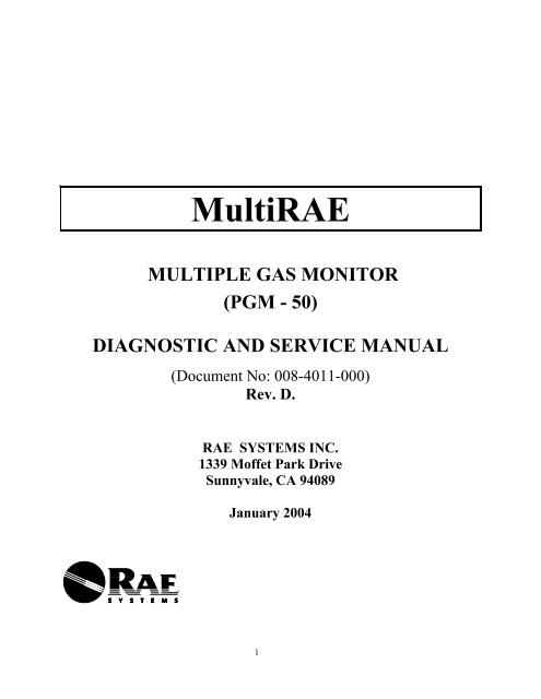
<strong>MultiRAE</strong><br />
MULTIPLE GAS MONITOR<br />
(PGM - 50)<br />
DIAGNOSTIC AND SERVICE MANUAL<br />
(Document No: 008-4011-000)<br />
Rev. D.<br />
RAE SYSTEMS INC.<br />
1339 Moffet Park Drive<br />
Sunnyvale, CA 94089<br />
January 2004<br />
1
I. Objective:<br />
This document provides detailed diagnostic and service procedures for service personnel<br />
in the factory and field service center. The procedure allows trained service personnel to<br />
perform a set of diagnostic tests to determine if the Unit Under Test (UUT) is functioning<br />
properly and performing within the specification. The procedure also helps to diagnose<br />
the possible causes of failures and suggest a number of corrective actions.<br />
II. Diagnostic and Service Requirements:<br />
1) In order to perform the PGM-50 diagnostic and service procedures, the service person<br />
should be very familiar with the procedure described in the PGM-50 Operation and<br />
Maintenance Manual (RAE Part Number: 008-4001).<br />
2) The following equipment is required:<br />
PC with Windows 3.1/ Windows 95 or above operating system and serial port.<br />
Computer interface cable (RAE Part Number 008-3003)<br />
ProRAE Suite software<br />
DC power supply (0-10V, 200 mA)<br />
Multi-meter (0-10VDC, 0-150 mA, 0-10 megaohm)<br />
20 ohm, 1W resistor<br />
Flat head screw driver<br />
#2 phillips screw driver<br />
Tweezers<br />
Battery connector with wires<br />
2
III. Trouble Shooting Guide:<br />
PGM-50 problems can be grouped into 4 major areas:<br />
1) Power supply - battery and charger<br />
2) Sensor and measurement<br />
3) Electronics<br />
4) Programming<br />
The following trouble shooting guide provides a quick reference for typical problems in<br />
each major area:<br />
1) Power Supply - Battery and Charger:<br />
Problem Possible Causes Test Procedures<br />
Can not turn on unit 1) battery charge is low<br />
2) battery pack fuse is blown<br />
3) battery is disconnected from the PCB or the<br />
battery wire is broken<br />
4) defective electronics<br />
1) Test 1.5 & 1.5A<br />
2) Test 1.1<br />
3) Test 1.1<br />
4) Test 3.1<br />
“bAt” message during<br />
operation<br />
Unit runs less than<br />
specified duration:<br />
Battery is warm during<br />
normal operation<br />
Charger light does not turn<br />
on<br />
Charger light does not<br />
change from red to green<br />
after overnight charging<br />
2) Sensor and Measurement:<br />
1) battery charge is low<br />
2) defective battery voltage measurement circuit<br />
3) excessive loading on the battery<br />
4) defective battery<br />
1) excessive loading on the battery<br />
2) memory effect of Ni-Cd battery<br />
3) old or defective Ni-Cd battery pack<br />
4) defective charger<br />
5) incomplete charging<br />
1) Test 1.5 & 1.5A<br />
2) Test 1.4<br />
3) Test 1.3<br />
4) Test 1.5 & 1.5A<br />
1) Test 1.3<br />
2) Test 1.5 & 1.5A<br />
3) Test 1.5 & 1.5A<br />
4) Test 1.6<br />
5) Test 1.7 & 1.5A<br />
1) excessive loading on the battery 1) Test 1.3<br />
1) broken wire inside PGM-50<br />
2) alkaline battery is used inside PGM-50<br />
3) defective charger<br />
4) bad LED<br />
1) defective charger<br />
2) defective charging circuit<br />
3) bad green LED<br />
4) bad battery<br />
5) ambient temperature too high or low<br />
1) Test 1.6<br />
2) Test 1.7<br />
3) Test 1.6<br />
4) Test 3.2<br />
1) Test 1.6<br />
2) Test 1.7<br />
3) Test 3.2<br />
4) Test 1.5 & 1.5A<br />
5) Test 1.8<br />
Problem Possible Causes Test Procedures<br />
Unit turns on, shows<br />
“Configuration changed”<br />
message<br />
1) sensor added or removed<br />
2) sensor is disconnected or loose from socket<br />
3) defective sensor<br />
1) Test 2.3<br />
2) Test 2.3<br />
3) Test 2.3<br />
Sensor is installed but not<br />
showing on LCD<br />
1) sensor is disconnected or loose from the socket<br />
2) defective electronics<br />
3) Sensor disabled<br />
1) Test 2.3<br />
2) Test 2.3<br />
3) Test 2.3<br />
3
No response or low<br />
response to gas input<br />
Slow response to gas input<br />
Erratic reading<br />
Non-zero background<br />
reading<br />
“CAL Err” message during<br />
calibration<br />
Flashing “CAL” message<br />
during normal operation<br />
Readings consistently<br />
wrong when exposed to gas<br />
During normal operation,<br />
“pump” message flashing<br />
“xxx installed<br />
bias error” message on<br />
LCD<br />
Calibrates OK, but LEL or<br />
VOC readings off by<br />
constant percentage.<br />
“Lamp” message during<br />
operation<br />
1) sensor input is blocked or dirty filter<br />
2) defective sensor module<br />
3) defective electronics<br />
4) weak, or leaking pump<br />
5) sensor cover plate missing, loose, or misaligned<br />
6) empty sensor position<br />
1) sensor input is blocked or dirty filter<br />
2) defective sensor module<br />
3) sensor has inherently slow response time<br />
4) weak or leaking pump<br />
5) sensor cover plate missing, loose, or misaligned<br />
6) empty sensor position<br />
1) incorrect calibration<br />
2) defective sensor module<br />
3) defective electronics<br />
4) weak or leaking pump<br />
1) dirty filter<br />
2) incorrect zero calibration or zero drift<br />
3) defective sensor module<br />
4) non-zero background<br />
5) carbon filter saturated or not installed<br />
1) incorrect calibration<br />
2) low gas pressure in gas cylinder<br />
3) defective sensor module or weak lamp<br />
4) leak in flow path<br />
5) defective electronics<br />
1) Test 2.1<br />
2) Test 2.4<br />
3) Test 2.4<br />
4) Test 2.2<br />
5) Test 2.1<br />
6) Test 2.1<br />
1) Test 2.1<br />
2) Test 2.4<br />
3) Test 2.4<br />
4) Test 2.2<br />
5) Test 2.1<br />
6) Test 2.1<br />
1).Test 2.5<br />
2) Test 2.4<br />
3) Test 2.4<br />
4) Test 2.2<br />
1) Test 2.1<br />
2) Test 2.6<br />
3) Test 2.4<br />
4) Test 2.6<br />
5) Test 2.1<br />
1) Test 2.5<br />
2) Test 2.5<br />
3) Test 2.4<br />
4) Test 2.1<br />
5) Test 2.4<br />
1) excessive negative zero drift of sensor 1) Test 2.6<br />
1) incorrect span calibration<br />
2) defective sensor module<br />
3) incorrect correction factor<br />
1) Gas inlet blocked or no connection to inlet port<br />
2) weak or inoperative pump<br />
3) pump stall threshold needs adjustment<br />
1) bias switch in wrong position for Toxic1 sensor<br />
2) defective sensor module<br />
1) Wrong calibration or measurement gas selection<br />
2) Incorrect lamp selected<br />
3) incorrect dilution ratio<br />
1) dirty PID sensor or lamp<br />
2) weak or defective lamp<br />
3) Lamp fail threshold adjustment needed<br />
1) Test 2.5<br />
2) Test 2.4<br />
3) Test 4.5<br />
1) Test 2.1<br />
2) Test 2.2<br />
3) Test 2.7<br />
1) Test 2.8<br />
2) Test 2.4<br />
1) Test 4.5<br />
2) Test 4.5<br />
3) Test 4.5<br />
1) Test 2.9<br />
2) Test 2.9<br />
3) Test 2.9<br />
3) Electronics:<br />
Problem Possible Causes Test Procedures<br />
LED, back light, buzzer or 1) defective component 1) Test 3.2<br />
vibrator alarm inoperative<br />
Missing segment on the<br />
LCD<br />
1) defective LCD<br />
2) temperature too low<br />
3) contrast set too low<br />
1) Test 3.3<br />
2) Test 3.3<br />
3).Test 3.3<br />
4
Random characters on the<br />
LCD<br />
No response to key press or<br />
can not turn off unit<br />
Back light does not turn on<br />
in low ambient light<br />
1) CPU hang-up<br />
2) defective electronics<br />
3) wrong firmware or error in firmware<br />
4) bad LCD<br />
5) temperature too high or low<br />
6) contrast too high or too low<br />
1) membrane disconnected from PCB<br />
2) defective membrane keys<br />
3) CPU hang-up<br />
1) defective electronics or component<br />
2) back light threshold needs adjustment<br />
3) unit configured for manual light turn on<br />
4) unit plugged into A/C adapter<br />
1) Test 3.3<br />
2) Test 3.3<br />
3) Test 4.1<br />
4) Test 3.3<br />
5) Test 3.3<br />
6) Test 3.3<br />
1) Test 3.1<br />
2) Test 3.1<br />
3) Test 3.1<br />
1) Test 3.3<br />
2) Test 3.3<br />
3) Test 3.3<br />
4) Test 3.3<br />
4) Programming<br />
Problem Possible Causes Test Procedures<br />
Unable to put into<br />
programming mode<br />
1) unit in display or text mode<br />
2) configured for password protection<br />
1) Test 4.2<br />
2) Test 4.3<br />
Lost password 1) unit configured for password access 1) Test 4.3<br />
“Unable to configure port” 1) port not available in this PC 1) Test 4.7<br />
message from ProRAE-50<br />
software<br />
“NAK” message from<br />
ProRAE-50 program<br />
1) Cable or connection problem<br />
2) port configuration problem<br />
3) PC hardware or operating system problem<br />
1) Test 4.7<br />
2) Test 4.7<br />
3) Test 4.7<br />
Time out message from<br />
ProRAE-50 software<br />
Can’t start data logging<br />
Shows “----“ instead of<br />
sensor name, does not<br />
display reading for sensor<br />
In data log, no readings for<br />
a sensor even though<br />
sensor and values show on<br />
display<br />
Unit beeps frequently but<br />
sensor readings are below<br />
the alarm limits<br />
No events recorded in PC<br />
after downloading data but<br />
data available in “View<br />
Datalog” menu.<br />
Unit beeps once per minute<br />
for no reason<br />
1) unit not in “Ready” mode<br />
2) cable or connection problem<br />
3) PC hardware or operating system problem<br />
1) datalogging disabled<br />
2) non-data logging unit<br />
1) Test 4.7<br />
2) Test 4.7<br />
3) Test 4.7<br />
1) Test 4.4<br />
2) Test 4.4<br />
1) sensor disabled 1) Test 4.5<br />
1) sensor not configured for data logging 1) Test 4.8<br />
1) alarm latched<br />
2) STEL or TWA limits exceeded<br />
3) low battery<br />
1) Short sample period causing data to be stored<br />
before header information written.<br />
1) Test 4.6<br />
2) Test 4.6<br />
3) Test 1.1<br />
1) Test 4.8<br />
1) comfort beep option turned on 1) Test 4.8<br />
IV.<br />
Diagnostic Mode:<br />
5
All RAE Systems gas monitors have a Diagnostic Mode for evaluating the condition of<br />
sensor, lamps, pumps, batteries, etc. This is distinct from the usual diagnostic tests the<br />
instrument performs automatically during routine start-up. All the usual functions can be<br />
performed in diagnostic mode, such as calibration and monitor set-up. In diagnostic<br />
mode all sensor outputs (and most other measured values) are displayed as raw values<br />
(a/d counts) without corrections or conversion to standard units. The following<br />
diagnostic procedures will make use of this mode when appropriate. Whenever the<br />
procedures state “place the unit in diagnostic mode” use the following steps to turn on the<br />
unit in this special mode.<br />
Entering diagnostic mode: With the unit turned off, hold down the [Y/+] key. While<br />
still holding this key down, depress and hold the [MODE] key. Hold both keys down<br />
until unit beeps and then release both keys. The <strong>MultiRAE</strong> will display “ON!” followed<br />
by the software version number, the firmware build date, and then the “Diagnostic Mode”<br />
message. If you hit the [Y/+] key when Diagnostic Mode is on the screen, the warm-up<br />
will be significantly shorter. The unit will then go through the normal start-up tests.<br />
Once the monitor is ready, the display will show raw values for each installed sensor,<br />
with the word “RAW” in the center of the bottom line of the display.<br />
In Diagnostic Mode, use [N/-] and [MODE] together; just as in normal mode, to enter the<br />
Programming Menu. CAUTION: When calibrating in Diagnostic Mode the system does<br />
not check for a difference between the span and zero calibration points. This can be<br />
useful if calibrating at a low level, (such as 10 ppm VOC). The user must manually<br />
verify, from the raw values in air and with calibration gas applied, that the sensors are<br />
working correctly. Use the [MODE] key alone to step through the special diagnostic<br />
screens in the following sequence:<br />
Version 1.xx Version 2.00 Version 3.xx<br />
Raw Sensor Values Raw Sensor Values Raw Sensor Values<br />
Sensor names Sensor names Sensor names<br />
PID Lamp Fail Threshold PID Lamp Fail Threshold RF test<br />
Battery type / Bias Battery type / Bias PID Lamp Fail Threshold<br />
PID 1X and 10X Range PID 1X and 10X Range Battery type / Bias<br />
LCD Contrast Adjustment LCD Contrast Adjustment PID 1X and 10X Range<br />
LEL Power On/Off Check LEL Power On/Off Check LCD Contrast Adjustment<br />
Clock/Voltage/Temperature Clock/Voltage/Temperature LEL Power On/Off Check<br />
Sensor expiration dates Sensor expiration dates Clock/Voltage/Temperature<br />
Pump Stall Threshold Pump Stall Threshold Sensor expiration dates<br />
Back Light On/Off Threshold Back Light On/Off Threshold Pump Stall Threshold<br />
Communicate with PC S/N and pump speed Back Light On/Off Threshold<br />
Battery deep discharge S/N and pump speed<br />
Power run down time Power run down time<br />
Communicate with PC Communicate with PC<br />
6
Software versions 1.05 and later allow access to the Programming Menu from the<br />
Diagnostic Mode even if the unit is configured in “Display” or “Text” modes. A valid<br />
password will be required if the unit has been configured with a password. This feature<br />
allows users to exit from these modes without using a PC.<br />
PROGRAMMING MODE<br />
Press [N] and [MODE] together for 3 seconds to begin.<br />
Calibrate Monitor<br />
[Y] to select, [N] to move to next menu, [MODE] to return to Display Mode.<br />
[Y] selects, [N] skips,[MODE] for next menu<br />
Fresh Air Calibration<br />
Multiple Sensor Calibration<br />
Single Sensor Calibration<br />
Modify Span Gas Value<br />
Change LEL/VOC Span Gas<br />
Change Alarm Limits<br />
Change High Alarm limit<br />
Change Low Alarm limit<br />
Change STEL alarm limit<br />
Change TWA alarm limit<br />
View or Change Datalog<br />
Clear All Data<br />
Change Datalog Period<br />
Select Data Type<br />
View Datalog<br />
Enable/Disable Datalog<br />
Change Monitor Setup<br />
Change Site ID<br />
Change User ID<br />
Change Alarm Mode<br />
Change User Mode<br />
Change Real Time Clock<br />
Change Back Light Mode<br />
Change Password<br />
Change Pump Speed<br />
Change Averaging Method<br />
Change Sensor Configuration<br />
Change LEL/VOC Gas Selection<br />
Enable / Disable Sensor<br />
Change Dilution Ratio<br />
Change PID Lamp (10.6 or 11.7)<br />
If not all of the above menus appear in Programming, go to “Change Monitor Setup” and<br />
change the User Mode to Program. Use Mode to step out of Programming and then<br />
return by pressing and holding the Mode and N/- keys.<br />
7
Once in Diagnostic Mode, Version 2.00 and above will allow switching between<br />
diagnostic and standard modes by pressing and holding both the [Y] and [MODE] keys.<br />
V. Diagnostic and Service Test Procedures:<br />
1.0 Power supply / Battery / Charger<br />
1.1 Battery Voltage Test:<br />
1.1.1 Turn off the power to the <strong>MultiRAE</strong>. Open the instrument cover by removing the 2<br />
flat head screws from the backside (see Figure 1).<br />
Figure 1<br />
8
1.1.2 Carefully remove the battery pack or alkaline battery adapter from the unit. Make<br />
sure that the battery or adapter is plugged into the jack.<br />
1.1.3 Unplug the battery from the battery jack connected to the PC board of the<br />
<strong>MultiRAE</strong>. Visually inspect the wires between the battery pack or adapter and the<br />
connector, and between the jack and the PC board, for signs of broken or frayed wires or<br />
loose connector pins.<br />
1.1.4 Use a voltmeter to measure the voltage between the 2 outside pins of the connector<br />
on the battery pack. Be careful to avoid shorting the two pins as this could blow the<br />
internal fuse and/or damage the batteries. If the voltage is less than 4.2V the unit will not<br />
turn on. If using alkaline (AAA) cells, replace them with fresh cells when the voltage is<br />
less than 4.4V. When the voltage is below 4.4V, charge the batteries, either in the unit or<br />
on the external charger (RAE part number 008-3027). After replacing or recharging the<br />
batteries, check the voltage again. Fresh alkaline batteries should read over 6V. Fully<br />
charged Li-Ion or Ni-Cad batteries should read over 4.8V.<br />
1.1.5 If the voltage reads 0, then the internal fuse is blown or there is a broken wire.<br />
Replace the battery pack or adapter.<br />
1.3 Battery loading<br />
1.3.1 Remove the battery from the unit. Set the DC power supply to 4.8V DC. Connect<br />
the negative output to pin 1 (black wire) of the spare battery connector. Connect the<br />
positive power supply output to the positive side of a current meter. Connect the negative<br />
side of the current meter to pin 3 (red wire) of the battery connector (see figure 2).<br />
DC POWER<br />
SUPPLY<br />
+<br />
-<br />
+ -<br />
DC<br />
CURRENT<br />
METER<br />
3<br />
1<br />
Figure 2<br />
1.3.2 Plug the connector into the mating connector in the <strong>MultiRAE</strong>. Current should be<br />
about 3 ma with the unit off. Turn on the unit and wait for it to complete the start up<br />
tests. The current will depend on the configuration of the <strong>MultiRAE</strong>:<br />
Basic unit:<br />
20 mA<br />
9
PID current:<br />
Pump current:<br />
LEL sensor:<br />
Other sensors:<br />
20 mA<br />
20 mA<br />
60 mA<br />
2-5 mA<br />
1.3.3 If the current exceeds the limits in the table above, then isolate the source of the<br />
excess consumption by removing components one at a time. CAUTION: turn off the<br />
power supply before removing sensors or lamps. The pump current can be checked by<br />
stalling the pump and observing the change in current.<br />
1.3.4 Replace the component found to consume excess current. If the cause of the excess<br />
current consumption cannot be isolated, then the unit must be returned to the factory or<br />
an authorized service center.<br />
1.4 Battery voltage Measurement Circuit<br />
1.4.1 Follow the steps in 1.3.1 (the current meter is not necessary).<br />
1.4.2 Turn on the power supply. Turn on the <strong>MultiRAE</strong>. Press [MODE] to get to the<br />
battery voltage display. The display should read 4.8V<br />
1.4.3 Increase the voltage to 6V. The display should read 6V.<br />
1.4.4 Slowly decrease the power supply voltage. At 4.4V the display should begin<br />
flashing “Bat”. At 4.2V the unit should turn off.<br />
1.4.5 If any of these tests fail, the unit should be returned to the factory for repairs.<br />
1.5 Battery Condition Tests (use for NiCd battery packs only)<br />
1.5.1 Charge the batteries for 8 hours, either in the <strong>MultiRAE</strong> or in an external charger<br />
(P/N 008-3027).<br />
1.5.2 Measure the voltage across pins 1 and 3 of the battery connector (test procedure<br />
1.1.4). If the voltage is 4.2V, then the battery is good and no further testing is needed. If the voltage<br />
is
Battery capacity Discharge time<br />
900 maH 3 hours<br />
1400 maH 5 hours<br />
1700 maH 6 hours<br />
Table 1.1 Battery discharge times<br />
1.5.4 Recharge the battery for 8 hours. Or place the battery in the external charger and<br />
activate the automatic discharging function before charging. (Discharging batteries<br />
should only be done with the NiCd battery pack, PN 500-0039-000) Repeat paragraphs<br />
1.5.2<br />
1.5.3 If the battery fails again, it must be replaced.<br />
1.5A Battery Condition Test without volt meter<br />
1.5.1A Charge batteries completely inside unit charge light turn green. Unplug charging<br />
adapter and turn monitor on in diagnostic mode. Allow unit to run down and turn off due<br />
to drained battery. Recharge battery and turn unit on in diagnostic mode. Press [MODE]<br />
repeatedly until you reach Run Time screen. If run time is less than 8 hours with a NiCd,<br />
or less than 12 hours with a Li-Ion battery, than replace the battery.<br />
1.6 AC Adapter Output Test<br />
1.6.1 Plug the 12VDC adapter into an appropriate AC source. Measure the voltage at the<br />
DC connector. The inside contact is positive. If the output is not at least 10V, then the<br />
adapter is defective and must be replaced.<br />
1.6.2 Inspect the DC connector. Make sure that the pin is at least 11 mm long and is not<br />
corroded or otherwise contaminated. Plug the AC adapter into the <strong>MultiRAE</strong> and into an<br />
AC outlet. With the battery removed from the unit, measure the voltage between pins 1<br />
and 2 of the connector in the <strong>MultiRAE</strong>. If the measured voltage is less than the voltage<br />
measured in paragraph 1.6.1, then there is a loose or broken wire or a poor contact. Trace<br />
the circuit from the external connector to the PC board to the battery connector to<br />
determine the cause.<br />
1.7 Battery Charging<br />
1.7.1 Remove the cover from the <strong>MultiRAE</strong>. Make sure there is a Ni-Cad battery pack<br />
(white) or Li-Ion battery pack (black or yellow) in the unit and that the battery connector<br />
is plugged in to the mating connector. The unit will not charge or operate from the AC<br />
adapter if the alkaline battery adapter (black) is installed.<br />
11
1.7.2 Perform the Battery Condition Test if the battery is a NiCd (Section 1.5), using the<br />
<strong>MultiRAE</strong> to charge the batteries. If the batteries fail, perform the AC Adapter Output<br />
Test (section 1.6.2). If the adapter output is less than 10V, then replace the adapter. If<br />
the adapter output is good, then replace the battery pack.<br />
1.8 Ambient Temperature<br />
1.8.1 Press the [MODE] key 7 times from the main display to show the date, time, and<br />
temperature. The temperature sensor is mounted on the digital PC board.<br />
1.8.2 Compare the displayed temperature to the actual room temperature. If either<br />
temperature is >40 °C the batteries may not charge properly. Charging Ni-Cad<br />
batteries at temperatures above 40°C may permanently damage the batteries.<br />
1.8.3 With the unit off and charging (red LED on), compare the ambient temperature to<br />
the temperature displayed in the unit. If the temperature displayed in the unit is more<br />
than 20°C warmer that ambient temperature, then the batteries are overheating during<br />
charging and should be replaced.<br />
1.8.4 If the temperature is colder than 10°C the batteries will not be charged to full<br />
capacity.<br />
1.8.5 If there is a large difference between the room temperature and the displayed<br />
temperature, but the unit and batteries do not feel warmer or colder than the room, then<br />
the temperature sensor or electronics need repair.<br />
2.0 Sensor and Measurement Tests<br />
2.1 Flow Related Problems (pump versions only)<br />
2.1.1 Check the external filter and connectors for dirt, obstructions, or leaks. If the<br />
external filter is wet it will block the flow of air and gas. If the external filter is<br />
contaminated, do not attempt to clean it. It must be replaced.<br />
2.1.2 Remove the cover to the <strong>MultiRAE</strong> and remove the gas piping plate. Check the gas<br />
piping plate and gasket for obstructions or leaks. Check for the presence of a carbon<br />
impregnated foam filter in the gas piping plate. This filter should only be installed over<br />
the CO filter. Remove and discard any carbon filters installed over any other sensors.<br />
When installed over the CO filter, this filter screens the CO sensor from VOCs which<br />
may affect the CO sensor. This filter should be replaced frequently. If the <strong>MultiRAE</strong><br />
otherwise works fine, but you are unable to get a stable of accurate VOC calibration, then<br />
remove the carbon disk filter.<br />
12
2.1.3 Check the tubing between the inlet port and the pump for kinks, obstructions, or<br />
leaks. Check that the pump outlet port is not loose, broken, or leaking.<br />
2.1.4 Make sure there are no empty sensor positions. There must be either a sensor or a<br />
dummy sensor block in all five sensor positions (pump models).<br />
2.1.5 Re-install the gas piping plate. Observe that the connector nipple fits into the pump<br />
manifold (<strong>MultiRAE</strong> Plus does not have the manifold) and that the gasket fits snuggly<br />
against all the sensors.<br />
Figure 3 Sensor Positions<br />
Note: <strong>MultiRAE</strong> Plus has pump mounted to gas plate.<br />
2.2 Pump problems<br />
13
2.2.1 With the pump on, connect a flow meter to the <strong>MultiRAE</strong> inlet connector. The<br />
minimum acceptable flow rate is 200 ml/min. on the high speed and 150 ml/min. on the<br />
low speed. Rev C. boards only have one speed (high). If the flow is too low, check for<br />
obstructions and leaks as in section 2.1.<br />
2.2.2 If there are no obstructions or leaks, and the pump volume is still low, check the<br />
voltage at the pump power terminals. It should be 3.5V. If the input voltage is correct,<br />
then the pump should be rebuilt or replaced (P/N 008-3043-002). Replacement<br />
diaphragms are available through RAE Systems (P/N 081-0007-000).<br />
2.3 Sensor missing or not identified<br />
2.3.1 Always check the Programming Mode to verify that all sensors are enabled. Enter<br />
the programming menu ([N] and [MODE] together). Press [N] 4 times, or until the<br />
display reads “Change Sensor Configuration” Answer “Y”. The second option under<br />
the “Change Sensor Configuration” menu is to Enable/Disable Sensors. When this<br />
option is selected the display shows all installed sensors with a “*” next to the sensors<br />
which are enabled. Use the [MODE] key to scroll the cursor through the sensors. [Y]<br />
Enables sensors and [N] disables sensors. Hold the [MODE] key down until the display<br />
shows “save” to exit from this function. When a sensor is disabled the instantaneous<br />
display screen will be blank in that sensor location. The “Display Sensor Location”<br />
screen (press [MODE] once from the instantaneous screen) shows “---“ in the sensor<br />
positions which have been disabled.<br />
2.3.2 Verify the sensor configuration: The <strong>MultiRAE</strong> sensors have sensor type and<br />
expiration date stored internally. During the power-on tests the unit identifies all<br />
installed sensors and compares this to the configuration list. Make a note of which<br />
sensors the unit does identify by pressing [MODE] once from the instantaneous display.<br />
Turn off the unit. Remove the top cover. Disconnect the battery. Failure to disconnect<br />
the battery before removing or installing sensors could blow the battery pack<br />
internal fuse. Remove the gas piping plate. Verify the identity of each installed sensor.<br />
Remove, inspect, and re-insert each sensor making sure each is fully seated in its socket.<br />
Be sure that the shorting pin is no longer across the bottom of the sensor. The tops of the<br />
sensors should all be at nearly the same height. Pay particular attention to any sensors<br />
which were not identified. If pins are missing or the sensor or circuit board shows signs<br />
of damage do not re-insert the sensor: it must be replaced.<br />
2.3.3 Re-connect the battery and turn on power. “Configuration changed” may appear<br />
now even if all the sensors are working. Note which sensors are identified when the unit<br />
warms up and if all the installed sensors are now identified, then turn off power and reassemble<br />
the unit. A full calibration must be performed before using the unit, as<br />
calibration data may have been lost. Sensors which require a bias (NO and NH 3 ) must be<br />
installed, unit turned on and running, for 24 hours before stable readings can be obtained.<br />
14
It is always good to run the unit for at least four hours after replacing any sensor. Or use<br />
a SensorRAE to pre-Burn-in the sensors.<br />
2.3.4 If the sensor configuration is still not correct, then either the sensor is bad or there is<br />
an electronic problem. If possible, try replacing the sensor that is not recognized with a<br />
known good sensor to determine if the problem is with the sensor or the unit. Note that if<br />
NONE of the sensors can be identified; try removing sensors one at a time. A bad<br />
memory chip on one sensor may prevent the monitor from reading any of the sensor IDs.<br />
If this fails to isolate the problem, then the problem is with the boards in the unit.<br />
2.4 Sensor Response Tests<br />
2.4.1 Verify that there are no flow obstructions, the pump is operating correctly, and the<br />
gas piping plate is properly installed. Turn on the unit in Diagnostic Mode (Section IV).<br />
After the start-up tests are complete the display will show “raw” values for all installed<br />
sensors, with “RAW” in the center of the lower row. Table 2.1 has the normal raw values<br />
for the sensors in air (fresh air value) and with the standard calibration gasses applied<br />
(span value). See TN-123 for most recent changes. The most important indicator of<br />
sensor operation is the delta value, which is the difference between the span output and<br />
the zero output. Response Time is the average time required for a sensor to reach 90%<br />
output.<br />
SENSOR FRESH<br />
AIR<br />
SPAN RANGE DELTA SPAN GAS RESPONSE<br />
TIME<br />
PID 310 – 450 2000 – 8500 ≥750 100 ppm 10 sec.<br />
Isobutylene<br />
LEL 310 – 1500 1300 – 2300 ≥100 2.5% Methane 15 sec<br />
O 2 860 – 1250 330 – 500 ≥200 99.9% N 2 15 sec<br />
CO 310 – 450 450 – 900 ≥50 50 ppm CO 20 sec<br />
H 2 S 310 – 450 600– 950 ≥50 10 ppm H 2 S 30 sec<br />
NO 310 – 450 420 – 750 ≥30 25 ppm NO 20 sec<br />
NO 2 310 – 450 400 – 1400 ≥30 5 ppm NO 2 25 sec<br />
SO 2 310 – 450 500 – 1700 ≥75 5 ppm SO 2 20 sec<br />
Cl 2 310 – 450 450 – 1200 ≥50 10 ppm Cl 2 60 sec<br />
NH 3 400 – 750 700 - 1300 ≥100 50 ppm NH 3 150 sec<br />
PH 3 310 - 450 700 - 1800 ≥50 5 ppm PH 3 60 sec<br />
HCN 310 - 450 400 - 500 ≥10 10 ppm HCN 60 sec<br />
Table 2.1 Raw Sensor Values<br />
15
2.4.2 Note the raw fresh air output of the sensor. Apply the span gas for this sensor and<br />
wait until the reading is stable to within a few counts. Note the raw “span” output of the<br />
sensor. Calculate the delta (span – fresh air).<br />
Note: Most sensors should increase when Span gas has been applied; the O2 sensor with<br />
Nitrogen is the only exception. If the LEL sensor drops when gas is applied, the sensor<br />
has been poisoned and needs to be replaced. See TN-144 for further information on<br />
Sensor Poisoning.<br />
2.4.3 Fresh air values significantly below or above the values in the chart generally<br />
indicate a dead sensor but could also be due to an electronic problem, especially if all the<br />
values are low or identical. First replace the sensor, if you get the same problem then the<br />
problem is most likely in the analog or digital board, and the unit must be returned to the<br />
factory for service.<br />
2.4.4 If the CO and H2S sensor RAW readings are extremely high, they could be<br />
temporarily poisoned due to excessive Methanol exposure. Turn the unit on in<br />
Diagnostic Modes and run the monitor in a clean environment, checking to make sure<br />
that the RAW values are dropping over time. Be sure to store the Lamp Cleaning Kit<br />
solution (Methanol) in a sealed container or removed from the <strong>MultiRAE</strong> kit. If it has<br />
been previously stored in the case, allow the case to air out for 24 hours before storing the<br />
monitor inside.<br />
2.4.5 The delta is the most significant indicator of sensor condition. Fresh air values<br />
slightly below the chart values are acceptable if the delta is above the minimum value. A<br />
low delta means that the sensor is not responding to the test gas and must be replaced.<br />
2.4.6 Refer to section 2.9 for further trouble shooting of the PID sensor.<br />
2.4.7 If the sensor takes a long time (relative to the normal response time) to reach a<br />
stable output, then either the sensor is bad, the sensor is not warmed up, or there is a leak<br />
in the gas path (pump models).<br />
2.5 Calibration<br />
2.5.1 Inaccurate or improper calibrations can cause erratic readings, especially if the unit<br />
is calibrated with a gas to which the unit has a low sensitivity or with a standard gas at a<br />
very low concentration. In normal operating mode the software checks for a minimal<br />
difference in sensor output between span and zero calibration data (20 to 35 A/D counts,<br />
depending on software revision). This check is skipped if the calibration is performed in<br />
Diagnostic Mode. Software revisions before 1.05 could display erratic oxygen readings<br />
if a span calibration had not been performed (i.e. single sensor calibration at a value other<br />
than 0%). Calibration without applying the span gas can result in invalid calibration data<br />
being stored. A common error is calibrating the oxygen sensor to 0% in air. Some<br />
16
sensors require time to warm up before their zero point is stable. Calibration without<br />
sufficient warm up could result in significant zero drift as the sensor warms up. New<br />
sensors should be warmed up for at least one hour before calibrating (NH 3 and NO<br />
sensors should be installed and the unit run for 24 hours prior to calibrating in order for<br />
the bias circuit to stabilize the sensors).<br />
2.5.2 To check the system response to calibration gasses, use the raw output values in the<br />
Diagnostic Mode (section IV). Apply the calibration gasses and observe that the sensor<br />
responds sufficiently.<br />
2.5.3 If the sensor is responding well to the chosen calibration gas, allow the unit to warm<br />
up for at least 15 minutes, still in the Diagnostic Mode. Switch from diagnostic mode to<br />
standard mode by pressing and holding both the [Y] and [MODE] keys. If the sensor<br />
zero continues to drift, then the sensor should be replaced.<br />
2.5.4 If the sensor zero point is stable, then, while still in Diagnostic Mode, and proceed<br />
to the calibration menu (hold down [N] and [MODE]. Perform a fresh air calibration<br />
followed by a single gas calibration for the sensor of interest. If the sensor under test is<br />
oxygen, then note that the default is to calibrate to 0% with 99.9% nitrogen (say [Y] to<br />
the 0% question) or with another gas that has no oxygen in the mixture.<br />
2.5.5 Check the span gas values under “Modify Span Gas” to make sure that the cylinder<br />
of gas you are using matches the span values of each gas. To adjust a span concentration<br />
use the [MODE] key to scroll, the [Y] key to enable, and the [N] key to disable. Hold<br />
[MODE] until “save” appears to exit from this function.<br />
2.5.6 If calibration fails despite a good response in paragraph 2.5.2, check the level of gas<br />
in the cylinder, if it is less than 250psi, use a new bottle of gas. Otherwise there is an<br />
electronic problem and the unit should be returned to the factory for service.<br />
2.5.7 If calibration is successful, then switch from diagnostic mode to standard mode by<br />
pressing and holding both the [Y] and [MODE] keys. Apply the test gas and observe if<br />
the unit is reading correctly. If it is not then it must be returned to the factory.<br />
2.6 Non-zero Background<br />
2.6.1 “Fresh air” or “zero” calibration should be done in an area known to be free of<br />
gasses, which would affect the sensors. Zeroing in the presence of such gasses will result<br />
in inaccurate readings, especially at low concentrations, or a “NEG” alarm on one or<br />
more of your sensors.<br />
2.6.2 If you are unsure of the purity of the air, or if you are seeing non-zero background<br />
readings after a good calibration, then use a bottle of “zero” air during the fresh air<br />
17
calibration. This is the only way to positively differentiate between a faulty sensor and a<br />
real background signal. If you obtain a good calibration with “zero” air, and then recheck<br />
the zero with the same bottle of “zero” air, then you can have confidence that the<br />
instrument is working properly and the background signal you are seeing is caused by<br />
something in the environment.<br />
2.6.3 If, after a “zero” air calibration, you do not obtain a stable zero when applying the<br />
“zero” air to the instrument, then the sensor does not have a stable zero point and must be<br />
replaced.<br />
2.7 Pump Stall Adjustment.<br />
2.7.1 The Pump alarm can occur if the pump current exceeds the stall threshold value or<br />
if the pump current is 0. The pump current may increase over the threshold value as the<br />
pump ages or if the diaphragm is stiff due to cold temperatures. It may be necessary to<br />
adjust the pump stall threshold when switching from low to high pump speed or when<br />
adding additional lengths of tubing (Rev. D boards). Pump current may also increase if<br />
the inlet is blocked or the vapor trap filter is clogged. Before adjusting the pump stall<br />
threshold, make sure the flow path is not obstructed. Do not attempt to clean a clogged<br />
filter: it must be replaced.<br />
2.7.2 Turn on the unit in Diagnostic Mode (Section IV). The pump alarm is disabled in<br />
Diagnostic Mode. Press the [MODE] key repeatedly until you get to the “Pump =”<br />
screen. The top line is the measured pump current, and the bottom line is the threshold<br />
value at which the pump will stall in normal operating mode. When operating properly<br />
the stall threshold should be 6 - 10 counts higher than the operating current (typically 20 -<br />
30 counts).<br />
2.7.3 If the pump current is 0 then check for loose or broken wires. If the wires are<br />
intact, check the voltage between the red and black wires. It should be 3.5V. If the<br />
voltage is correct, then replace the pump assembly. If the voltage is not correct, then the<br />
unit will have to return to the factory for repair.<br />
2.7.4 If the pump is operating, block the inlet with your finger and observe the change in<br />
pump current:<br />
No change or only a few counts:<br />
1) Pump current < stall current means there is a leak in the flow path<br />
between your finger and the pump intake. Check the filter assembly, the<br />
inlet valve, the internal tubing, the pump inlet nipple, and the pump<br />
diaphragm. Clean or replace any parts that are dirty or leaking<br />
18
2) Pump current > stall current means that the inlet is blocked. Check the<br />
filter assembly, the inlet valve, and the internal tubing. Clean or replace<br />
any parts that are dirty or leaking<br />
Changes, but pump current still < stall current<br />
Check for leaks. If none are found, then reduce the stall threshold to be less<br />
than the current with the inlet blocked. Use the [N/-] key to reduce the stall<br />
limit.<br />
Changes, but pump current > stall current even with inlet unblocked<br />
Check for obstructions. If none are found, then raise the stall threshold.<br />
Use the [Y/+] key to raise the stall value to a point midway between the<br />
open and blocked values.<br />
2.7.4 If the pump current exceeds 50 counts with no obstructions, then the pump<br />
assembly should be replaced.<br />
2.8 Bias Switch for Toxic 1 Sensor<br />
2.8.1 The NO and NH 3 sensors require a bias to operate correctly. This bias signal is<br />
only available in the Toxic 1 position and is set by a switch or jumper on the analog<br />
board. This switch, which is located under the gas piping plate immediately behind the<br />
front panel LEDs, must be ON for these two sensors and OFF for all other sensors.<br />
2.8.2 The computer checks the bias during the start up tests and compares the sensor type<br />
to the bias condition. It will display the “xxx installed bias error” message if the bias is<br />
not correct for the type of sensor installed in the Toxic 1 position.<br />
2.8.3 Check the type of sensor installed in the Toxic 1 position and the position of the<br />
bias switch. If the switch is in the proper position for the type of sensor and the error<br />
message still appears, and then the analog board may be bad.<br />
2.8.4 Verify that the sensor type displayed in the Toxic 1 position matches the sensor<br />
type installed. If they match, then the analog board is bad and must be replaced. If they<br />
do not match, then the sensor is bad (or incorrectly programmed) and must be replaced.<br />
2.9 PID Sensor and Lamp Tests<br />
2.9.1 The “Lamp” error is an indication of a problem with the lamp current. A dirty or<br />
contaminated sensor often causes high readings of the VOC sensor, especially when<br />
exposed to moisture. A weak or inoperative lamp often causes low readings or no<br />
19
esponse to test gas. Readings that go up to 2000 ppm and then decrease may be caused<br />
by saturation of the VOC sensor by gas concentrations over 2000 ppm.<br />
2.9.2 To test the sensor and lamp, place the unit in Diagnostic Mode (Section IV).<br />
2.9.3 Press the [MODE] key to reach the Lamp Failure Threshold screen. The threshold<br />
value is set to about 6 counts above the value obtained with no lamp in the PID. Page 8-4<br />
of the <strong>MultiRAE</strong> manual contains information on setting this value.<br />
2.9.4 If the Lamp Failure threshold is OK, press [MODE] repeatedly to get back to the<br />
raw data screen. Refer to the PID values in table 2.1.<br />
2.9.5 Zero values below the normal range, or a weak response to test gas, may indicate<br />
that the lamp is not illuminating sufficiently, or that the UV light is blocked by<br />
contamination on the lamp window. Remove the cover, gas piping plate, PID static<br />
shield, and PID sensor block. Remove the lamp, clean the crystal with anhydrous<br />
methanol, and reinstall the lamp. Turn on the unit. Caution: wear safety glasses to<br />
protect your eyes from UV light. Be aware that there are high voltages across the<br />
lamp electrodes. Check for a visible violet glow from the lamp. If there is no glow,<br />
then replace the lamp.<br />
2.9.6 Examine the sensor block for contamination, condensation, or corrosion. Soak and<br />
agitate the sensor in anhydrous methanol, preferably in an ultrasonic cleaner. Dry<br />
thoroughly. If there are still visible signs of contamination or corrosion, then replace the<br />
sensor.<br />
2.9.7 Reassemble and test the raw sensor output. If the delta value is still low try<br />
replacing the lamp, then the sensor. If the delta values are still low, then there is an<br />
electronic problem.<br />
3.0 Electronic Troubleshooting<br />
3.1 Power On Problem<br />
3.1.1 If the unit will not turn on, first check the battery pack, AC adapter, and fuses. If<br />
the alkaline battery adapter is installed, then the A/C adapter will not power the unit.<br />
Both the rechargeable batteries and the alkaline adapter have internal fuses, which can<br />
not be replaced.<br />
3.1.2 Try resetting the microprocessor by unplugging the battery pack. Wait a few<br />
minutes, and then reconnect the battery.<br />
20
3.1.3 If the unit will still not turn on, then either the electronics or the membrane switch is<br />
defective, and the unit must be returned to the factory for service.<br />
3.1.4 If the unit turns off before completing the warm up tests, then the battery pack is not<br />
charged. As soon as the LEL, pump, and VOC lamp turn on the voltage drops below the<br />
shut off value. This is usually an indication that the battery internal fuses are blown. If<br />
the battery connectors appear normal, then try replacing the battery.<br />
3.2 LED, Buzzer, Back light problems<br />
3.2.1 Test the Green battery charge indicator LED by opening the unit and removing the<br />
battery pack. Then plug the AC adapter into the unit. The green LED should illuminate.<br />
If it does not, then the indicator board must be replaced by the factory.<br />
3.2.2 Test the red battery-charging indicator by plugging in the A/C adapter with a Ni-<br />
Cd/Li-Ion battery connected to the unit. The red LED should illuminate. If not, then<br />
proceed as in section 3.2.1<br />
3.3.3 The alarm buzzer should beep once during the power on self-test. The buzzer is on<br />
the analog PC board, next to the VOC and TOX1 sensor positions. If the buzzer does not<br />
beep during power on or power off, then it must be replaced. Do not attempt to replace<br />
just the buzzer; the unit will need to be sent in to the factory for service.<br />
3.3.4 Depressing the [N] key can turn on the back light LEDs for the LCD automatically<br />
in low ambient light, or manually.<br />
3.3.5 If the back light does not come on in low ambient light (in normal mode only, in<br />
diagnostic mode the backlight will not turn on), check whether the unit is in auto or<br />
manual back light mode. This information is the last selection under the Change Monitor<br />
Setup sub-menu in the programming menu. If the unit is in auto mode and the lights still<br />
do not come on in low ambient light, then check the back light threshold in Diagnostic<br />
Mode (Section IV). This menu can be used to adjust the turn on threshold and to check<br />
operation of the light sensor. The circular window at the top right of the front instrument<br />
display is for the sensor. Cover the window with a finger (with the A/C adapter<br />
unplugged) while in the back light threshold display. The value in the display should<br />
change. If it does not, then the indicator board must be replaced by the factory.<br />
3.3.6 If the backlight is in manual mode, use the [N] key to turn it on. It will turn off<br />
automatically after a few seconds to conserve battery life.<br />
3.3.7 If the back light can not be turned on in either mode, the unit must be returned for<br />
service.<br />
21
3.3.8 If the green or red battery charge indicator LEDs are on (i.e. the A/C adapter is<br />
plugged in), then auto back light mode will not work. The light from the LEDs will be<br />
detected by the photo sensor, which will keep its output above the threshold value.<br />
3.3 LCD problems<br />
3.3.1 Faint or missing characters or bleeding characters, in the LCD screen may be<br />
corrected by adjusting the display contrast. Press the [Mode] key to reach the LCD<br />
contrast screen. Use the [+] and [-] keys to increase or decrease the contrast.<br />
3.3.2 In very warm environments the LCD may show bleeding around the edge of the<br />
characters. If this is excessive, then adjust the contrast downward. In very cold<br />
environments it may be necessary to increase the contrast to see all of the characters.<br />
3.3.3 Random or mal-formed characters in the display could also be caused by a CPU<br />
hang up or by a problem with the firmware. To reset the CPU, unplug the battery pack<br />
then reconnect the batteries. If the problem persists, then reload the firmware (Section<br />
4.1).<br />
3.3.3 If these steps do not resolve the problem, then the unit must be returned to the<br />
factory to have the display replaced.<br />
4.0 Troubleshooting Software/Programming Problems<br />
4.1 Reloading<br />
4.1.1 Odd characters on the display, failure to respond to key presses with a keypad that<br />
test good or erratic operation may be caused by an error in the firmware. Re-loading the<br />
basic operating program can solve this. The ProRAE Suite diskette includes a copy of<br />
the firmware or you can download the ProRAE .Suite and the <strong>MultiRAE</strong> PGM-50<br />
firmware from our website: www.raesystems.com.<br />
4.1.2 Connect the <strong>MultiRAE</strong> to the PC serial port and press Mode repeatedly until you<br />
reach “Communicate with PC” Press Y/+, unit will say “Monitor will pause” Press<br />
Y/+ key again. Unit should read “PC Comm.”<br />
4.1.3 Open ProRAE Suite and select Option, Load Firmware<br />
4.1.4 It is very important to shut down everything on your computer that could interfere<br />
such as the Internet, screen savers, etc. If the firmware loading process is interrupted, the<br />
monitor will be turned off and will not be able to turn it on. If this happens, the unit will<br />
need to come back to the factory for a boot load.<br />
22
4.1.5 Select the most recent .AO7 file that corresponds with your monitor and select<br />
Open<br />
4.1.6 After loading the firmware, turn monitor back on in diagnostic mode and return to<br />
PC Comm.<br />
4.1.7 Select Open and File on ProRAE Suite and change Files of Type to .cfg. Select the<br />
default configuration file that corresponds to your instrument and select Open.<br />
4.1.8 You can edit the configuration file by selecting Edit, Configuration<br />
4.1.9 After making the all changes you want, select Options, Config All. This will<br />
rewrite the entire configuration and finish the rewriting of the monitor.<br />
4.2 Display or Text Only Modes<br />
4.2.1 The text mode is the simplest mode of operation. The monitor will display the<br />
sensor name after the monitor is turned on. The user can press the [MODE] key to see<br />
the instantaneous gas concentration reading, battery voltage or enter the PC<br />
communication menu. The user can get into the calibration mode from text mode to do<br />
calibrations, but cannot change most of the parameters. In the display mode, the<br />
<strong>MultiRAE</strong> PLUS Multi-gas Monitor is able to display all the information in the text<br />
mode. In addition, the following information is also available by pressing the [MODE]<br />
key: peak, minimum, STEL, TWA, run time in hours and minutes, temperature in degree<br />
C, datalog mode (or enable / disable datalogging operation in manual datalog mode),<br />
LEL/VOC gas names, printing and communication with a PC options. The user cannot<br />
get into the calibration mode from display mode, so the user cannot do calibration and<br />
cannot change any of the parameters. The third option is “Programming” mode, which<br />
gives users full access to all the menus and features.<br />
4.2.2 Modes can be changed from the PC configuration file (datalogging units only) or<br />
from the “Change Monitor Set up” sub-menu under the programming menu.<br />
4.2.3 To exit from Text or Display modes in a datalogging unit, use the PC program<br />
(ProRAE-50). Select a configuration file (.CFG file), using either the default or a custom<br />
file. Make sure the Program mode button is selected, and send the configuration to the<br />
<strong>MultiRAE</strong>.<br />
4.2.4 The procedure to exit from Display modes in non-datalog units, or if a PC is not<br />
available, depends on the firmware version number. This is the number that appears on<br />
the LCD when the unit is first turned on.<br />
23
Version 1.03 and earlier: press [MODE] to get to the “Communicate with PC”<br />
screen. Press [Y] to get the “Monitor will pause OK” screen. Press [N]. A bug<br />
in the software will drop you into the programming menu. Press [MODE] until<br />
you get to the “Change Monitor Setup” screen. Press [Y], and then press [N]<br />
until you get to the “Change User Mode” screen. Press [Y], then select<br />
Programming Mode. Press [MODE] to exit and save changes.<br />
Version 1.04: requires a PC to exit from Display mode.<br />
Version 1.05 and later: Start the unit in Diagnostic Mode (section IV). Press [N]<br />
and [MODE] together to enter the programming menu. You will be required to<br />
enter the password to proceed. The default password is 0000. Hold the MODE<br />
key down after entering the password to get to the programming menus. If you do<br />
not know the password you will not be able to proceed (see section 4.3). Once in<br />
the programming menu, proceed as above for version 1.03 to change the user<br />
mode. After making and saving the changes, turn the unit off to exit from<br />
Diagnostic Mode.<br />
4.3 Password Protection<br />
4.3.1 Units may be configured with a password from the PC configuration file. There are<br />
3 security levels that work in conjunction with the password:<br />
Security level 0:<br />
Security level 1:<br />
Security level 2:<br />
User cannot enter programming menu at all.<br />
User must enter password to enter programming menu.<br />
No password needed to enter programming menu.<br />
4.3.2 To change the password from the ProRAE software you must perform a firmware<br />
upgrade and send the configuration file to the unit using “Config All”<br />
4.4 Datalogging Enable/Disable<br />
4.4.1 Datalogging functions may be enabled in the ProRAE Suite. Refer to section 5.13<br />
of the operation manual. A three-digit code, which is unique for each serial number, is<br />
required to enable datalogging. This code is supplied when the data logging option is<br />
purchased and is on file at RAE Systems.<br />
4.4.2 To determine if datalogging is enabled, observe the software version number which<br />
is the second screen displayed when the unit is turned on. If the version number ends in<br />
“D”, then datalogging is enabled.<br />
4.4.3 Individual sensors may be selected or deselected for datalogging, either from a<br />
configuration file and the ProRAE-50 program, or from the “Enable/Disable Datalog”<br />
24
function, which is the last selection in the “View or Change Datalog” sub-menu under the<br />
programming menu. Sensors which are enabled for datalogging have a “*” next to their<br />
name in this display. As usual, use the [MODE] key to scroll, the [Y] key to enable, and<br />
the [N] key to disable. Hold [MODE] until “save” appears to exit from this function.<br />
4.5 Sensor Configuration<br />
4.5.1 The programming menu has a sub-menu for sensor configuration. Within this<br />
section users may select among the list of gasses for LEL and VOC measurement. The<br />
<strong>MultiRAE</strong> has the capability to select up to 50 gases for calibration and up to 50 different<br />
gases for measurement with both the LEL and VOC sensors. The system will<br />
automatically correct for the relative responses of any combination. The factory defaults<br />
are isobutylene for both calibration and measurement on the VOC and methane for both<br />
functions on the LEL. You can also Enable/Disable sensors (see section 2.3), set a<br />
dilution ratio (for use with dilution probe), and configure for use with either the 10.6 eV<br />
or 11.7 eV lamp. These powerful features can lead to confusion if the user has not<br />
checked the configuration before calibrating and using the unit. If the unit is tested with<br />
a known gas and the readings are always off by a constant percentage, check both the<br />
calibration gas and the measurement gas selections in the programming menu. The<br />
calibration gas is under the “Calibrate Monitor” sub-menu (“Change LEL/VOC span<br />
gas”). The measurement gas is under the “Change Sensor Configuration” menu<br />
(Change LEL/VOC gas”).<br />
4.5.2 Enter the programming menu ([N] and [MODE] together). Press [N] 4 times, or<br />
until the display reads “Change Sensor Configuration” Answer “Y”.<br />
4.5.3 The first selection is to select the LEL and VOC gas. Press [Y]. The LEL gas<br />
selection is displayed (if there is a LEL sensor installed). Press [N] to select a different<br />
gas. At this point the [+] and [-] keys scroll through the gas list. Once you have found<br />
the desired gas, press the [MODE] key and the display will say “Save”. Press [Y] to<br />
save. If the display says, “Not saved”, then the security level is set to 0 and changes are<br />
not allowed. Once a gas is selected, you can change the correction factor. Check the<br />
correction factor for accuracy by looking at TN-156. The VOC gas selection is now<br />
displayed. Follow the same steps to select a VOC gas. Once a gas is selected, you can<br />
change the correction factor. Check the correction factor for accuracy by looking at TN-<br />
106. The default gases, Methane and Isobutylene both have correction factors of 1.<br />
4.5.4 “Change Lamp Type” is used when you replace the current lamp with a new type of<br />
lamp. The instrument does not know what type of lamp it has installed until you select<br />
the correct lamp. To verify which lamp is in the unit, turn off unit. Remove the cover,<br />
gas piping plate, PID static shield, and PID sensor block. Remove the lamp and check<br />
the number etched on the side. The numbers 106 means it is a 10.6 lamp and the number<br />
117 mean that the lamp is an 11.7. Always clean the lamp before reinstalling (see section<br />
25
2.9). Turn monitor on in diagnostic mode and put unit into programming. Press [N] until<br />
you reach “Change Sensor Configuration” press [Y]. Press [N] until you reach “change<br />
Lamp Type” press [Y]. If the monitor agrees with the lamp you have installed hit [Y],<br />
other wise press [N] until the correct lamp is displayed. Press [Y] and the unit will ask to<br />
save, press [Y] again to save.<br />
4.5.5 Unless you are using the dilution ration to extend the range of the PID or to add O2<br />
to an LEL stream, the dilution ration should be 1. (See TN-167 for proper use of the<br />
dilution fitting)<br />
4.6 Alarms<br />
4.6.1 The <strong>MultiRAE</strong> has several types of alarms, which can be distinguished by the rate<br />
at which the unit beeps and by the messages on the display. See section 2.5 of the<br />
operation manual for a full listing of alarms and messages. When a sensor output<br />
exceeds an alarm setting, the unit will beep at 1, 2, or 3 beeps per second, and the sensor,<br />
which is causing the alarm, will flash on the LCD. The newest versions of the firmware<br />
also flash the name of the alarm in the sensor position (High, Low, STEL, etc.).<br />
4.6.2 If Alarm Latching is ON then the alarm will continue to beep even after the<br />
condition which caused the alarm has been cleared. Press the [Y] key to clear the alarm.<br />
For example, testing with 100 ppm isobutylene will cause a high alarm (with the factory<br />
default alarm limits) on the VOC. If the alarm is latched, then the unit will continue to<br />
beep even after the gas is removed. Alarm latching can be set or reset from the ProRAE-<br />
50 program or from the “Change Monitor Setup” sub-menu in the programming menu.<br />
The pump alarm is always a latching alarm and must be acknowledged before it will turn<br />
off.<br />
4.6.3 An alarm at 1 beep per second with a flashing sensor symbol indicates that the<br />
STEL or TWA limit has been exceeded. This alarm may continue to beep even after<br />
removal of the gas, which caused the alarm, because of the time averaged nature of these<br />
alarms. Use the [MODE] key to examine the STEL and TWA value screens to determine<br />
if this is the reason for the alarm. The only way to clear this alarm is to turn the unit off<br />
and then on again.<br />
4.6.4 If the LEL sensor exceeds 100% LEL, the LEL sensor turns off, for safety reasons.<br />
The alarm will beep at 3 flashes per second and the “LEL Off” message will flash on the<br />
screen. The unit must be powered off to restart the LEL sensor.<br />
4.7 PC Communication Problems<br />
26
4.7.1 Serial communications is a simple and reliable method of exchanging information<br />
between devices. Problems can arise from failure of the PC, failure of the unit, problems<br />
with the cable, or operator error. A serial port tester, which is nothing more than a box<br />
with a male connector on one end, a female connector on the other end, and a bank of<br />
LEDs for each line, is an extremely valuable, yet inexpensive, tool for diagnosing serial<br />
communication problems. It is connected between the two devices. The LEDs show the<br />
status of each line at a glance.<br />
4.7.2 Keep a spare serial cable for testing. Cables do break from time to time. If there is<br />
a serial communication failure, first try a different cable, or try a known good unit with<br />
the cable. If the cable tests well, then try the following tests.<br />
4.7.3 The most common PC problems are incorrect port selection, interference by a serial<br />
mouse, or failure of the serial port.<br />
4.7.4 If the port selected is not available on the PC, then Windows will provide an error<br />
message.<br />
4.7.5 If the <strong>MultiRAE</strong> is not in “Ready” mode it will not respond to serial<br />
communications. Press the [MODE] key until the “Communicate with PC” window<br />
appears. Press [Y] Answer [Y] to “Monitor will pause OK” The display then reads<br />
“Ready” and the unit is waiting to communicate. If no messages are received after a<br />
timeout period, then the unit will remain at “Ready” but will no longer communicate.<br />
Press [Mode] until you reach the communications and try again.<br />
4.7.6 If the port is available, but it is not the one the <strong>MultiRAE</strong> is connected to, there will<br />
be a time out error. This will also happen if the port is the correct port but is not<br />
transmitting properly. The port tester can quickly identify if the port is the correct port.<br />
When sending a message to the <strong>MultiRAE</strong> the LED on the transmit line from the PC<br />
should blink. If it does not, then nothing is being sent out this port.<br />
4.7.7 Similarly, the port tester can show if messages are being sent from the <strong>MultiRAE</strong>.<br />
The receive line from the PC should blink when the <strong>MultiRAE</strong> is sending data to the PC.<br />
If you see the PC transmit line blink and do not see the receive line blink in response,<br />
then the unit is not responding. It must be returned for service.<br />
4.7.8 A “NAK received” message from ProRAE-50 could have several causes:<br />
Check the cable and connections.<br />
Check for proper operation of the serial port.<br />
Try reloading the ProRAE program, as corrupted files could also cause this error.<br />
Try reloading the firmware.<br />
If all of the above fail, the unit must be returned for service.<br />
27
4.8 PC Software Problems<br />
4.8.1 The ProRAE-50 programs works reliably with Windows 3.1, Windows 95,<br />
Windows 2000 and Windows XP. Some users have reported problems with Windows<br />
NT.<br />
4.8.2 The default configuration file included on the ProRAE-50/ProRAE Suite diskette is<br />
the factory default configuration. Refer to the operation manual for details about the use<br />
of the configuration file to set-up the <strong>MultiRAE</strong>.<br />
4.8.3 If you are able to download data, but data for a particular sensor is missing, check<br />
the configuration of the unit. Each sensor must be enabled for datalogging. This is<br />
different from the “Enable/Disable Sensor” function in section 4.5.<br />
4.8.4 It is generally a good idea to clear data before beginning a datalog session. This is<br />
done in the unit via the “View or change datalog” sub-menu from the Programming<br />
Menu. If data is not cleared samples taken at different times may confuse the graphing<br />
program, especially if some events from a later clock time precede events with an earlier<br />
clock time.<br />
4.8.4 If you download data, and you see in the message line at the bottom of the screen<br />
that a number of bytes have been transferred, but there are no events listed, then check<br />
the datalog period. Very short periods may confuse the ProRAE program, because<br />
datalogging is not halted when clearing memory. If a data sample is written to memory<br />
after clearing, but before the <strong>MultiRAE</strong> writes a new event header in memory, then the<br />
ProRAE program will not find the first event header and will report no events. You can<br />
prevent this by turning off datalogging before clearing memory, or by selecting a longer<br />
datalog period temporarily. ProRAE-50 releases after 2.00 will correct this problem.<br />
4.8.5 If you receive a “…datalog.raw” error message, no data has been stored in the unit.<br />
Verify that the “L” is flashing while the unit is running, or that you are running the unit<br />
for the entire datalog period. As you lengthen the datalog period, if the unit does not run<br />
for that entire time period, no data will be stored.<br />
4.8.6 If you are able to download data, but your readings are very high, the instrument<br />
was turned on in Diagnostic mode and saved the RAW readings of the sensors. The unit<br />
must be turned on in normal operations, for correct readings.<br />
28
QUICK REFERENCE GUIDE<br />
MULTIRAE CALIBRATION WITH 4 CALIBRATION GAS MIX<br />
1. Turn on <strong>MultiRAE</strong> in a safe, clean air environment. Let unit warm up for 5 minutes.<br />
2. Press [N/-] and [MODE] together for 5 seconds. Display shows “Calibrate Monitor”<br />
3. Press [Y/+]. Display shows “Fresh Air Calibration”<br />
4. Press [Y/+]. Display shows results for each sensor followed by “Multiple sensor calibration”<br />
5. Press [Y/+]. Display names sensors selected for span calibration. All others show as “----“.<br />
6. Apply the gas mixture (RAE P/N 600-0050) to the filter fitting (pump models) or the calibration adapter<br />
(diffusion models).<br />
7. Press [Y/+]. Unit displays “Apply mixed gas now…40” and counts down for 40 seconds. The unit then shows<br />
results. After a short pause the unit displays “Calibration done! Turn off the gas” followed by “Single sensor<br />
calibration”<br />
8. Turn off the gas and disconnect the bottle. Press [MODE] twice to return to the main display, or press [Y/+]<br />
for VOC sensor calibration.<br />
9. The sensor names are displayed. Push [MODE] until VOC is selected (flashing character).<br />
10. Turn on the isobutylene gas and apply the gas to the unit.<br />
11. Press [Y/+]. Display shows “Apply VOC gas” followed by “Calibration in progress…40”. Unit counts down<br />
40 seconds then shows “VOC cal’ed. Reading=xxx”, where “xxx” is the calibration result.<br />
12. Turn off the gas and disconnect from the <strong>MultiRAE</strong>. Push [MODE] twice to return to the main display.<br />
MULTIRAE BUMP TEST PROCEDURE<br />
1. Turn on <strong>MultiRAE</strong> in a safe, well-ventilated, clean air environment. Let unit warm up for 5 minutes.<br />
2. O 2 should read 20.9%. All other sensors should read 0. If readings are not correct, perform a fresh air<br />
calibration. (See above)<br />
3. If unit zeros correctly, turn on the quick check four gas mix (RAE P/N 600-0060) and apply it to the filter fitting<br />
(pump models) or calibration adapter (diffusion models).<br />
4. After 40 seconds the unit should read as follows:<br />
CO 90 - 110 ppm<br />
H 2 S 45 - 55 ppm<br />
LEL 45 - 55%<br />
O 2 14 - 16%<br />
5. Disconnect the gas and turn off the valve.<br />
6. Turn on the 100 ppm isobutylene gas and attach it to the vapor trap or calibration adapter.<br />
7. After 40 seconds the VOC should read 90-110 ppm.<br />
8. Disconnect the gas and turn off the valve.<br />
9. Wait for the unit to return to VOC=0 and O 2 =20.9.<br />
10. If the span readings were incorrect, then recalibrate the sensors (see above).<br />
11. If the span readings were all within the specified limits the unit is ready to use.<br />
29
PGM-50 Diagnostic & Service Procedure<br />
PROGRAM MODE<br />
Instantaneous display of values<br />
[N] + [M] for 3 seconds:<br />
Security level = 0: No action<br />
Security level = 1: Password check<br />
Wrong password: Instantaneous display<br />
Correct password: Programming mode<br />
Security level = 2: Programming mode<br />
[N]: Toggle backlight<br />
[Y]: Test alarm/stop alarm<br />
[M]<br />
Display sensor positions<br />
[M]<br />
Display peak values<br />
[M]<br />
Display minimum values<br />
[M]<br />
Display STEL values<br />
[M]<br />
Display TWA values<br />
[M]<br />
Display battery voltage<br />
[M]<br />
Display clock / run time / internal temperature<br />
[M]<br />
Is unit configured for manual datalog<br />
Yes: Display Start/Stop datalog<br />
[Y]: Start or stop datalog<br />
[M]: Go to “Display LEL gas name”<br />
No: Display datalog mode<br />
[M]<br />
Display LEL gas name<br />
[M]<br />
Display VOC gas name<br />
[M]<br />
Communicate with PC<br />
[Y]: Monitor will pause OK<br />
[Y]: Ready…<br />
[N]: Return to Instantaneous display<br />
[M] or [N]<br />
Return to Instantaneous display<br />
30
PGM-50 Diagnostic & Service Procedure<br />
Firmware Releases:<br />
Version 3.12A 3.12 3.11D<br />
Date 10/14/2003 6/4/2003 5/22/2003<br />
Error<br />
"Datalog Disabled"<br />
display<br />
drive for vibration alarm to<br />
RF control fixed<br />
work in Silent Mode<br />
New<br />
RF Control Enable/Disable<br />
Version 3.11C 3.11B 3.11A<br />
Date 3/18/2003 1/13/2003 8/29/2002<br />
Error<br />
check correction factor<br />
of LEL<br />
verify Silent Mode<br />
higher than 6<br />
New<br />
Enable Run Silent Mode<br />
Version 3.11 3.10A 3.10<br />
Date 8/29/2002 11/7/2001 9/26/2001<br />
Error fix LEL sensor linearity fix Power-On Zero,<br />
Fix O2 temp<br />
compensation<br />
so Fresh Air is not required<br />
Verify LEL correction<br />
factors<br />
reset NH3 low alarm to 25ppm<br />
check LEL "OFF" alarm<br />
change time out for low battery<br />
change Lamp driver<br />
prompts Single Sensor<br />
fix first point in datalog<br />
Calibration after Power-on Zero<br />
fix alarm when sensor is<br />
disabled<br />
New<br />
add disable Fresh Air<br />
Cal<br />
Default User mode is Text<br />
Mode<br />
Calibration Date is updated<br />
during<br />
Remove "View Datalog" Default setting has On-line Single Sensor calibration<br />
add temperature units<br />
selection printing turned off add User ID<br />
"Reset Peak" moved to<br />
idle mode<br />
add wireless abilities<br />
add "Change Temperature<br />
Units"<br />
31
PGM-50 Diagnostic & Service Procedure<br />
<strong>MultiRAE</strong> Service Parts<br />
32
PGM-50 Diagnostic & Service Procedure<br />
Part Number Description Price (ea.)<br />
008-2002-005 Cover screw, PGM 50 (5) 10.00<br />
008-2003-005 Cover screw washer, PGM 50 (5) 5.00<br />
430-0070-005 Gas plate screw,4P and 5P (5) 5.00<br />
430-0058-005 Gas plate washer (5) 5.00<br />
008-2027-000 Gas inlet nipple 8.00<br />
008-2020-001 Washer for inlet nipple and pwr jack 2.00<br />
008-2009-000 Dummy sensor 5.00<br />
008-2017-000 PID static shield 5.00<br />
008-2020-001 Gas inlet power jack washer 2.00<br />
008-2027-000 Gas inlet fitting assembly. (nipple) 8.00<br />
008-3003-000 Interface cable assembly 40.00<br />
008-3006-005 Charcoal filter for CO (5) 9.00<br />
008-3006-020 Charcoal filter for CO (20) 32.00<br />
008-3007-000 PID sensor assembly 75.00<br />
008-3013-000 Calibration Adapter (Diffusion Models) 15.00<br />
008-3014-000 External Filter with quick connect adapter (1) 10.00<br />
008-3014-001 External Filter with barb fitting adapter (1) 5.00<br />
008-3016-000 Calibration adapter (pump) 10.00<br />
008-3017-000 Housing cover 25.00<br />
008-3018-000 Housing case (Bottom & Top) 75.00<br />
008-2004-000 Housing bottom 50.00<br />
027-2001-000 QRAE Housing Top 25.00<br />
027-2004-000 QRAE Housing Bottom 50.00<br />
008-3022-010 Water vapor traps (pack of 10) 38.00<br />
008-3022-100 Water vapor traps (pack of 100) 345.00<br />
008-3027-000 External battery charger for NiCd Batteries 85.00<br />
008-3029-000 I/O port rubber cover (10) 20.00<br />
008-3035-002 Gas piping plate, 5P, Aluminum/Teflon hybrid 42.00<br />
008-3036-002 Gas piping plate, 4P, Aluminum/Teflon hybrid 42.00<br />
008-3037-002 Gas piping plate, 4D, Aluminum/Teflon hybrid 42.00<br />
008-3040-000 Packing case with foam 56.00<br />
008-3043-002 Pump assembly 295.00<br />
008-3044-002 5P pump on aluminum gas plate 337.00<br />
008-3045-002 4P pump on aluminum gas plate 337.00<br />
008-4011-000 Service Manual, PGM 50 50.00<br />
050-0010-000 10.6 eV, ¼” lamp 195.00<br />
050-0011-001 11.7 eV, ¼” lamp in ampoule 345.00<br />
050-0030-000 9.8 eV, ¼” lamp 245.00<br />
081-0002-000 Lamp cleaning kit 28.00<br />
081-0007-000 Pump rebuild kit 40.00<br />
090-2001-000 Remote probe tubing adapter 9.50<br />
411-0017-024 Tygon tubing, pump connections (per foot) 5.00<br />
500-0039-000 1700 mAH Ni-Cad battery 155.00<br />
500-0037-000 Li-Ion battery pack 155.00<br />
008-2104-002 Membrane key panel 40.00<br />
027-2104-000 QRAE Membrane key panel 40.00<br />
008-2021-005 Stand-off, digital PCB (5) 5.00<br />
008-2022-005 Stand-off, analog PCB (5) 5.00<br />
500-0029-000 Alkaline Adapter for 4 AA 12.00<br />
008-1171-001 LEL Sensor Module,PGM-50 175.00<br />
008-1161-000 O2 Sensor Module,PGM-50 120.00<br />
008-1111-000 H2S Sensor Module,PGM-50 195.00<br />
008-1112-000 CO Sensor Module,PGM-50 195.00<br />
008-1113-000 SO2 Sensor Module,PGM-50 195.00<br />
33
PGM-50 Diagnostic & Service Procedure<br />
008-1114-000 NO Sensor Module,PGM-50 195.00<br />
008-1115-000 NO2 Sensor Module,PGM-50 195.00<br />
008-1116-001 Cl2 Sensor Module,PGM-50 195.00<br />
008-1117-000 HCN Sensor Module,PGM-50 395.00<br />
008-1118-000 NH3 Sensor Module,PGM-50 395.00<br />
008-1119-000 PH3 Sensor Module,PGM-50 395.00<br />
008-1120-000 ClO2 Sensor Module,PGM-50 395.00<br />
008-1121-000 EtO Sensor Module,PGM-50 395.00<br />
34