Microcontroller Solutions TechZone Magazine, April 2011 - Digikey
Microcontroller Solutions TechZone Magazine, April 2011 - Digikey
Microcontroller Solutions TechZone Magazine, April 2011 - Digikey

You also want an ePaper? Increase the reach of your titles
YUMPU automatically turns print PDFs into web optimized ePapers that Google loves.
Channel 5<br />
SIGSEL[2:0]<br />
SOURCESEL[5:0]<br />
EDSEL[1:0]<br />
APB bus<br />
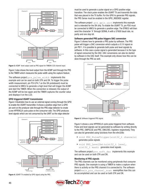
must be used to generate a pulse signal on a GPIO positive edge<br />
transition. The clock pulse enables the USART TX and transmits the data<br />
that was placed in the TX buffer. For the GPIO to generate PRS signals,<br />
the PRS Sense must be enabled in the GPIO_INSENSE register.<br />
Signals from<br />
producer<br />
peripherals<br />
SWPULSE[5]<br />
SWLEVEL[5]<br />
Reg<br />
Signals to<br />
consumer<br />
perpherals<br />
The software project prs_gpio_uart implements this example<br />
and is intended for the DK only. To enable the USART TX, pin PD0 must<br />
be connected to VMCU to generate a positive edge. The EFM32 will then<br />
send the character ‘X’ through SERIAL A with a 57600 baud rate, no<br />
parity and one stop bit.<br />
Producer<br />
Side<br />
ACMP<br />
Output Level<br />
PRS<br />
TIMER0<br />
Reload&Start + Capture&Stop<br />
Consumer<br />
Side<br />
Software generated PRS pulse triggers DAC conversion<br />
Figure 5 shows how to generate a PRS pulse by software. The PRS<br />
pulse will trigger a DAC conversion which outputs a 0.5 V signal on<br />
pin PB11. It is possible to generate both pulse and level signals by<br />
software. In this case a pulse signal is generated because it is the type<br />
of signal consumed by the DAC. DAC conversions can also be started<br />
by software in the DAC itself. This example only shows how this can be<br />
done through the PRS as well.<br />
Level<br />
Figure 3: ACMP level output used as PRS signal for TIMER0 CC0 channel input.<br />
Level<br />
Channel 5<br />
SIGSEL[2:0]<br />
Figure 3 also shows the level output from the ACMP sent through the PRS<br />
to the TIMER which measures the pulse width using the capture feature.<br />
The software project prs_pulse_width implements this<br />
example and can be used on both STK and DK. To trigger the pulse<br />
width measurement, pin PC4 (P4.7 on the DK protoboard) must be<br />
connected to VMCU to generate a high level that will trigger the ACMP<br />
and start the TIMER. When the connection is released, the output of<br />
the ACMP will be low again and the TIMER captures the counter value<br />
and displays it on the LCD.<br />
GPIO triggered USART transmission<br />
Figure 4 illustrates how to use an external signal coming through the GPIO<br />
to enable the USART transmitter. It shows a positive edge from a GPIO<br />
pin sent on the producer side through the PRS edge detector to create<br />
a one HFPERCLK cycle pulse on the consumer side. The GPIO produces<br />
level signals which are not consumed by the UART so the edge detector<br />
Producer<br />
Side<br />
Channel 5<br />
Signals from<br />
producer<br />
peripherals<br />
GPIO<br />
Output Level<br />
Positive Edge<br />
PRS<br />
SIGSEL[2:0]<br />
SOURCESEL[5:0]<br />
EDSEL[1:0]<br />
SWPULSE[5]<br />
SWLEVEL[5]<br />
UART<br />
Enable TX<br />
Figure 4: USART TX enabled by GPIO signal using the PRS.<br />
Reg<br />
1 HFPERCLK Pulse<br />
APB bus<br />
Signals to<br />
consumer<br />
perpherals<br />
Consumer<br />
Side<br />
Producer<br />
Side<br />
Signals from<br />
producer<br />
peripherals<br />
Figure 5: Software triggered PRS signal.<br />
SOURCESEL[5:0]<br />
EDSEL[1:0]<br />
SWPULSE[5]<br />
SWLEVEL[5]<br />
APB bus<br />
Figure 5 shows a one HFPERCLK cycle pulse triggered from software.<br />
Pulse and level signals can be generated by software by writing directly<br />
to the PRS_SWPULSE and PRS_SWLEVEL registers respectively. They<br />
can also be generated using functions from the efm32lib:<br />
• void PRS_PulseTrigger(uint32_t channels)<br />
generates pulse signals<br />
• void PRS_LevelSet(uint32_t level,<br />
uint32_t mask) generates level signals<br />
PRS<br />
DAC0<br />
Start conv.<br />
Signals to<br />
consumer<br />
perpherals<br />
Consumer<br />
Side<br />
The software project prs_soft_dac implements this example<br />
and can be used on both STK and DK.<br />
Monitoring of PRS signals<br />
The PRS channels can be monitored using peripherals that consume<br />
PRS signals. One example is using a TIMER to make a capture when<br />
there is activity on the PRS channel it is connected to. The software<br />
project main_prs_channel_scan exemplifi es how this can<br />
be accomplished and can be used on both STK and DK.<br />
Reg<br />
1 HFPERCLK Pulse<br />
46