Microcontroller Solutions TechZone Magazine, April 2011 - Digikey
Microcontroller Solutions TechZone Magazine, April 2011 - Digikey
Microcontroller Solutions TechZone Magazine, April 2011 - Digikey

Create successful ePaper yourself
Turn your PDF publications into a flip-book with our unique Google optimized e-Paper software.
CAN Primer: Creating<br />
Your Own Network<br />
by Bob Boys, ARM<br />
CAN is a flexible network that is easy to<br />
implement. If you are considering networking<br />
topologies for your next embedded design,<br />
this article will set you on the right path.<br />
CAN is extensively used in automobiles and trucks and can be found<br />
in multiple applications. There are many “application” layers available<br />
for CAN, such as ISO 15765 (cars), J1939 (trucks), and CANopen<br />
(factory automation), but it is very easy to develop your own protocol<br />
to fi t and simplify your needs. Modern CAN transceivers provide a<br />
stable and reliable CAN physical environment without the need for<br />
expensive coaxial cables. Most of the mystery of CAN has dissipated<br />
over the years. There is plenty of example CAN software available to<br />
help you quickly develop your own network.<br />
A CAN controller is a sophisticated device. Nearly all the features<br />
of the CAN protocol described below are automatically handled by<br />
the controller with almost no intervention by the host processor. All<br />
you need to do is confi gure the controller by writing to its registers,<br />
write data to the controller, and the controller then does all the<br />
housekeeping work to get your message on the bus.<br />
The controller will also read any frames found on the bus and hold<br />
them in a small FIFO memory. It will notify the host processor that this<br />
data is available, which is then read from the controller. The controller<br />
also contains a hardware fi lter mechanism that can be programmed<br />
to ignore the CAN frames you do not want passed to the processor.<br />
For the purposes of this article; we will assume a CAN network<br />
consists of the physical layer (the voltages and the wires) and a frame<br />
consisting of an ID and a varying number of data bytes. CAN has the<br />
following general attributes:<br />
1. 11- or 29-bit ID and from zero to eight data bytes. These can be<br />
dynamically changed “on the fl y.”<br />
2. Peer-to-Peer network. Every node can see all messages from all<br />
other nodes. A node cannot read its own messages.<br />
3. Nodes are easy to add. Attach one to the network with two wires<br />
plus a ground.<br />
4. Higher priority messages are sent fi rst depending on the value of<br />
the ID. A lower ID has the highest priority.<br />
5. Automatic retransmission of defective frames. A node will “busoff”<br />
if it causes too many errors.<br />
6. Speeds from approximately 10 Kbps to 1 Mbps. All nodes must<br />
operate at the same frequency.<br />
7. The twisted differential pair provides excellent noise immunity<br />
and some decent bus fault protection.<br />
8. The CAN system will work with the ground connection at<br />
different DC levels or no ground at all.<br />
The CAN system layout<br />
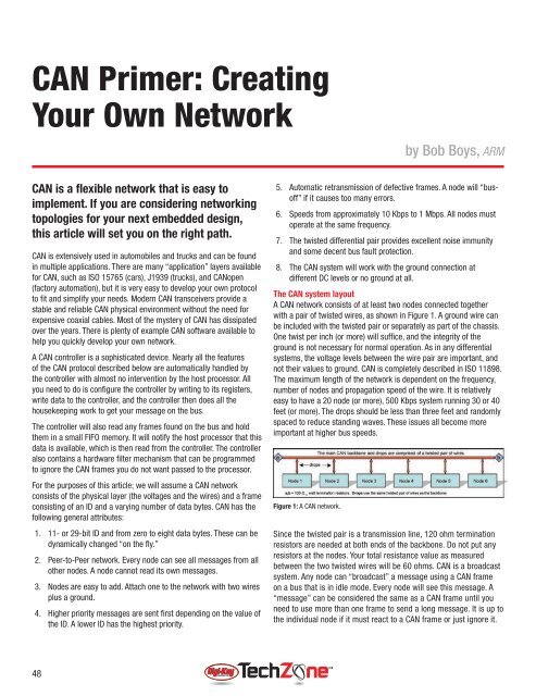
A CAN network consists of at least two nodes connected together<br />
with a pair of twisted wires, as shown in Figure 1. A ground wire can<br />
be included with the twisted pair or separately as part of the chassis.<br />
One twist per inch (or more) will suffi ce, and the integrity of the<br />
ground is not necessary for normal operation. As in any differential<br />
systems, the voltage levels between the wire pair are important, and<br />
not their values to ground. CAN is completely described in ISO 11898.<br />
The maximum length of the network is dependent on the frequency,<br />
number of nodes and propagation speed of the wire. It is relatively<br />
easy to have a 20 node (or more), 500 Kbps system running 30 or 40<br />
feet (or more). The drops should be less than three feet and randomly<br />
spaced to reduce standing waves. These issues all become more<br />
important at higher bus speeds.<br />
Figure 1: A CAN network.<br />
Since the twisted pair is a transmission line, 120 ohm termination<br />
resistors are needed at both ends of the backbone. Do not put any<br />
resistors at the nodes. Your total resistance value as measured<br />
between the two twisted wires will be 60 ohms. CAN is a broadcast<br />
system. Any node can “broadcast” a message using a CAN frame<br />
on a bus that is in idle mode. Every node will see this message. A<br />
“message” can be considered the same as a CAN frame until you<br />
need to use more than one frame to send a long message. It is up to<br />
the individual node if it must react to a CAN frame or just ignore it.<br />
48