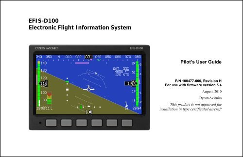
EFIS-D100 Electronic Flight Information System - Dynon Avionics
EFIS-D100 Electronic Flight Information System - Dynon Avionics
EFIS-D100 Electronic Flight Information System - Dynon Avionics

Create successful ePaper yourself
Turn your PDF publications into a flip-book with our unique Google optimized e-Paper software.
<strong>EFIS</strong>-<strong>D100</strong><br />
<strong>Electronic</strong> <strong>Flight</strong> <strong>Information</strong> <strong>System</strong><br />
Pilot’s User Guide<br />
P/N 100477-000, Revision H<br />
For use with firmware version 5.4<br />
August, 2010<br />
<strong>Dynon</strong> <strong>Avionics</strong><br />
This product is not approved for<br />
installation in type certificated aircraft
Contact <strong>Information</strong><br />
<strong>Dynon</strong> <strong>Avionics</strong>, Inc.<br />
19825 141 st Place NE<br />
Woodinville, WA 98072<br />
Phone: (425) 402-0433 - 7:00 AM – 5:00 PM (Pacific Time) Monday - Friday<br />
Fax: (425) 984-1751<br />
<strong>Dynon</strong> <strong>Avionics</strong> offers online sales, extensive support, and continually-updated information on its products via its Internet sites:<br />
www.dynonavionics.com –<strong>Dynon</strong> <strong>Avionics</strong> primary web site; including:<br />
docs.dynonavionics.com – Current and archival documentation.<br />
downloads.dynonavionics.com – Software downloads.<br />
support.dynonavionics.com – Support resources.<br />
store.dynonavionics.com – <strong>Dynon</strong>’s secure online store for purchasing all <strong>Dynon</strong> products 24 hours a day.<br />
wiki.dynonavionics.com – <strong>Dynon</strong> <strong>Avionics</strong>’ Documentation Wiki provides enhanced, extended, continuously-updated online documentation<br />
contributed by <strong>Dynon</strong> employees and customers.<br />
forum.dynonavionics.com – <strong>Dynon</strong> <strong>Avionics</strong>’ Internet forum where <strong>Dynon</strong> customers can interact and receive <strong>Dynon</strong> technical support<br />
outside of telephone support hours. A key feature of the forum is that it allows the exchange of diagrams, photos, and other types of files.<br />
newsletter.dynonavionics.com – <strong>Dynon</strong>’s email newsletter.<br />
blog.dynonavionics.com – <strong>Dynon</strong>’s blog where you can find new and interesting <strong>Dynon</strong>-related content.<br />
Copyright<br />
2003-2009 <strong>Dynon</strong> <strong>Avionics</strong>, Inc. All rights reserved. No part of this manual may be reproduced, copied, transmitted, disseminated or stored in any<br />
storage medium, for any purpose without the express written permission of <strong>Dynon</strong> <strong>Avionics</strong>. <strong>Dynon</strong> <strong>Avionics</strong> hereby grants permission to download a<br />
single copy of this manual and of any revision to this manual onto a hard drive or other electronic storage medium to be viewed for personal use,<br />
provided that such electronic or printed copy of this manual or revision must contain the complete text of this copyright notice and provided further<br />
that any unauthorized commercial distribution of this manual or any revision hereto is strictly prohibited.
Introduction<br />
<strong>Information</strong> in this document is subject to change without notice. <strong>Dynon</strong> <strong>Avionics</strong> reserves the right to change or improve its products and to make<br />
changes in the content without obligation to notify any person or organization of such changes. Visit the <strong>Dynon</strong> <strong>Avionics</strong> website<br />
(www.dynonavionics.com) for updates and supplemental information concerning the use and operation of this and other <strong>Dynon</strong> <strong>Avionics</strong> products.<br />
Limited Warranty<br />
<strong>Dynon</strong> <strong>Avionics</strong> warrants this product to be free from defects in materials and workmanship for three years from date of shipment. <strong>Dynon</strong> <strong>Avionics</strong><br />
will, at its sole option, repair or replace any components that fail in normal use. Such repairs or replacement will be made at no charge to the customer<br />
for parts or labor. The customer is, however, responsible for any transportation cost. This warranty does not cover failures due to abuse, misuse,<br />
accident, improper installation or unauthorized alteration or repairs.<br />
THE WARRANTIES AND REMEDIES CONTAINED HEREIN ARE EXCLUSIVE, AND IN LIEU OF ALL OTHER WARRANTIES<br />
EXPRESSED OR IMPLIED, INCLUDING ANY LIABILITY ARISING UNDER WARRANTY OF MERCHANTABILITY OR FITNESS FOR A<br />
PARTICULAR PURPOSE, STATUTORY OR OTHERWISE. THIS WARRANTY GIVES YOU SPECIFIC LEGAL RIGHTS, WHICH MAY<br />
VARY FROM STATE TO STATE.<br />
IN NO EVENT SHALL DYNON AVIONICS BE LIABLE FOR ANY INCIDENTAL, SPECIAL, INDIRECT OR CONSEQUENTIAL DAMAGES,<br />
WHETHER RESULTING FROM THE USE, MISUSE OR INABILITY TO USE THIS PRODUCT OR FROM DEFECTS IN THE PRODUCT.<br />
SOME STATES DO NOT ALLOW THE EXCLUSION OF INCIDENTAL OR CONSEQUENTIAL DAMAGES, SO THE ABOVE LIMITATIONS<br />
MAY NOT APPLY TO YOU.<br />
<strong>Dynon</strong> <strong>Avionics</strong> retains the exclusive right to repair or replace the instrument or firmware or offer a full refund of the purchase price at its sole<br />
discretion. SUCH REMEDY SHALL BE YOUR SOLE AND EXCLUSIVE REMEDY FOR ANY BREACH OF WARRANTY.<br />
These instruments are not intended for use in type certificated aircraft at this time. <strong>Dynon</strong> <strong>Avionics</strong> makes no claim as to the suitability of its products<br />
in connection with FAR 91.205.<br />
<strong>Dynon</strong> <strong>Avionics</strong>’ products incorporate a variety of precise, calibrated electronics. Except for replacing the optional internal backup battery in <strong>EFIS</strong>based<br />
products per the installation guide, our products do not contain any field/user-serviceable parts. Units that have been found to have been taken<br />
apart may not be eligible for repair under warranty. Additionally, once a <strong>Dynon</strong> <strong>Avionics</strong> unit is opened up, it will require calibration and verification<br />
at our Woodinville, WA offices before it can be considered airworthy.<br />
<strong>EFIS</strong>-<strong>D100</strong> Pilot’s User Guide<br />
iii
Table of Contents<br />
Contact <strong>Information</strong>..............................................................................................................................................................ii<br />
Copyright..............................................................................................................................................................................ii<br />
Limited Warranty ................................................................................................................................................................iii<br />
1. Introduction<br />
1-1<br />
Before You Fly..................................................................................................................................................................1-1<br />
OEM Installations..............................................................................................................................................................1-1<br />
Warning .............................................................................................................................................................................1-2<br />
About this Guide................................................................................................................................................................1-2<br />
2. Product Overview<br />
2-1<br />
<strong>EFIS</strong>-<strong>D100</strong> Hardware........................................................................................................................................................2-1<br />
ADAHRS Operation..........................................................................................................................................................2-3<br />
3. Product Operation<br />
3-1<br />
Front Panel Layout ............................................................................................................................................................3-1<br />
Display...............................................................................................................................................................................3-2<br />
Menus ................................................................................................................................................................................3-6<br />
4. Available Pages<br />
4-1<br />
<strong>EFIS</strong> Main pages ...............................................................................................................................................................4-2<br />
HSI Page............................................................................................................................................................................4-9<br />
Times Page ......................................................................................................................................................................4-10<br />
Lists Pages.......................................................................................................................................................................4-11<br />
<strong>EFIS</strong>-<strong>D100</strong> Pilot’s User Guide<br />
v
Table of Contents<br />
Menu Pages......................................................................................................................................................................4-11<br />
5. <strong>EFIS</strong> Operation<br />
5-1<br />
POWER – Power on/off ................................................................................................................................................... 5-1<br />
BARO – Changing Altimeter Setting ............................................................................................................................... 5-1<br />
BUGS – Setting Bug Markers .......................................................................................................................................... 5-2<br />
LISTS – Using Checklists and Data Panels...................................................................................................................... 5-5<br />
SETUP – Setting Preferences ........................................................................................................................................... 5-7<br />
INFO – <strong>Information</strong>al Items ............................................................................................................................................5-11<br />
DIM – Changing screen brightness..................................................................................................................................5-13<br />
TIMER – Setting and using a timer .................................................................................................................................5-14<br />
OATSET – Setting Temperature Offset ..........................................................................................................................5-15<br />
DATLOG – Logging and retrieving data.........................................................................................................................5-15<br />
6. HSI Operation<br />
6-1<br />
Required Connections....................................................................................................................................................... 6-1<br />
Accessing the HSI/DG Page............................................................................................................................................. 6-1<br />
HSI Display Basics ........................................................................................................................................................... 6-2<br />
Navigation Radio Overlay ................................................................................................................................................ 6-4<br />
GPS Overlay..................................................................................................................................................................... 6-7<br />
HSI Menu Structure.......................................................................................................................................................... 6-9<br />
7. Autopilot Operation<br />
7-1<br />
Introduction and Resources .............................................................................................................................................. 7-1<br />
<strong>EFIS</strong> AP Indicators........................................................................................................................................................... 7-2<br />
AP Modes ......................................................................................................................................................................... 7-5<br />
AP Control Methods......................................................................................................................................................... 7-9<br />
vi<br />
<strong>EFIS</strong>-<strong>D100</strong> Pilot’s User Guide
Table of Contents<br />
<strong>EFIS</strong> Autopilot Control .....................................................................................................................................................7-9<br />
AP74 Autopilot Control...................................................................................................................................................7-11<br />
Disengage/Control Wheel Steering (CWS) Pushbutton ..................................................................................................7-15<br />
Optional Preflight Checklist ............................................................................................................................................7-17<br />
8. Alerts<br />
8-1<br />
Alarm Indicators................................................................................................................................................................8-1<br />
Multiple Alarms.................................................................................................................................................................8-3<br />
DSAB Alerts......................................................................................................................................................................8-3<br />
9. Appendix<br />
9-1<br />
Appendix A: Serial Data Output........................................................................................................................................9-1<br />
Appendix B: PC Support Program ....................................................................................................................................9-3<br />
Appendix C: Troubleshooting ...........................................................................................................................................9-3<br />
Appendix D: <strong>EFIS</strong>-<strong>D100</strong> Specifications............................................................................................................................9-8<br />
<strong>EFIS</strong>-<strong>D100</strong> Pilot’s User Guide<br />
vii
1. INTRODUCTION<br />
Thank you for purchasing the <strong>Dynon</strong> <strong>Avionics</strong> <strong>EFIS</strong>-<strong>D100</strong>. This section provides some important cautionary information<br />
and general usage instructions for this manual.<br />
Before You Fly<br />
We strongly recommended that you read this entire guide before attempting to use the <strong>EFIS</strong>-<strong>D100</strong> in an actual flying<br />
situation. Additionally, we encourage you to spend time on the ground familiarizing yourself with the operation of the<br />
product. While first learning to use the instrument in the air, we recommend you have a backup pilot with you in the<br />
aircraft. Finally, we encourage you to keep this manual in the aircraft with you at all times. This document is designed to<br />
give you quick access to information that might be needed in flight. CAUTION: in a flying situation, it is the pilot’s<br />
responsibility to use the product and the guide prudently.<br />
OEM Installations<br />
If your <strong>EFIS</strong>-<strong>D100</strong> is installed by an OEM distributor, you may find that you are unable to access some menus and<br />
settings. Some <strong>Dynon</strong> distributors customize various areas of the <strong>EFIS</strong>-<strong>D100</strong> firmware to maintain a consistent pilot<br />
experience and minimize integration issues across a large number of installations. Currently, OEMs can customize<br />
access levels to the following settings on <strong>Dynon</strong> systems: EMS GLOBAL setup menu, EMS SENSOR setup menu, fuel<br />
calibration, trim calibration, flaps calibration, GPS/NAV setup menu, screen configurations, data logging, and<br />
checklists/data panels. OEM distributors have the option of customizing some or all of these areas. Please contact your<br />
aircraft’s manufacturer if you have any questions about how your unit has been customized.<br />
<strong>EFIS</strong>-<strong>D100</strong> Pilot’s User Guide 1-1
Introduction<br />
Warning<br />
<strong>Dynon</strong> <strong>Avionics</strong>’ products incorporate a variety of precise, calibrated electronics. Except for replacing the optional<br />
internal backup battery in <strong>EFIS</strong>-based products per the installation guide, our products do not contain any field/userserviceable<br />
parts. Units that have been found to have been taken apart may not be eligible for repair under warranty.<br />
Additionally, once a <strong>Dynon</strong> <strong>Avionics</strong> unit is opened up, it will require calibration and verification at our Woodinville,<br />
WA offices before it can be considered airworthy.<br />
About this Guide<br />
This guide serves two purposes. The first is to help you configure and get acquainted with the <strong>EFIS</strong>-<strong>D100</strong>‘s many<br />
functions. The second is to give you quick access to vital information. For detailed technical and installation information,<br />
please refer to the <strong>EFIS</strong>-<strong>D100</strong> Installation Guide.<br />
In the electronic (.PDF) version of this manual, page and section references in the Table of Contents and elsewhere act as<br />
hyperlinks taking you to the relevant location in the manual. The latest version of this manual may be downloaded from<br />
our website at docs.dynonavionics.com.<br />
This guide discusses the most common operation scenarios. If you have an operational issue that is not discussed in this<br />
guide, you can find additional operational information on <strong>Dynon</strong>’s Internet sites:<br />
wiki.dynonavionics.com – <strong>Dynon</strong>’s Documentation Wiki provides enhanced, extended, frequently updated online<br />
documentation contributed by <strong>Dynon</strong> employees and customers.<br />
forum.dynonavionics.com – <strong>Dynon</strong>’s Online Customer Forum is a resource for <strong>Dynon</strong> <strong>Avionics</strong> customers to<br />
discuss installation and operational issues relating to <strong>Dynon</strong> <strong>Avionics</strong> products. The Forum is especially useful for<br />
pilots with uncommon aircraft or unusual installation issues. For customers that cannot call <strong>Dynon</strong> Technical<br />
Support during our normal business hours, the Forum is a convenient way to interact with <strong>Dynon</strong> <strong>Avionics</strong><br />
Technical Support. The Forum allows online sharing of wiring diagrams, photos, and other types of electronic files.<br />
1-2 <strong>EFIS</strong>-<strong>D100</strong> Pilot’s User Guide
Introduction<br />
The following icons are used in this guide:<br />
Any text following this icon describes functionality available only with the HS34 HSI Expansion Module<br />
connected to your system.<br />
Any text following this icon describes functionality available only with the AP74 Autopilot Interface Module<br />
connected to your system.<br />
Any text following this icon describes functionality that is possible when multiple <strong>Dynon</strong> <strong>Avionics</strong> products are<br />
networked together via the <strong>Dynon</strong> Smart <strong>Avionics</strong> Bus (DSAB).<br />
Any text following this icon refers to a setting or situation which merits particularly close attention.<br />
<strong>EFIS</strong>-<strong>D100</strong> Pilot’s User Guide 1-3
2. PRODUCT OVERVIEW<br />
This section provides a general overview of the various parts of the <strong>EFIS</strong>-<strong>D100</strong> as well as a theory of operation. The<br />
information in this section serves as a reference only and helps familiarize you with the inner workings of the unit. It<br />
should not be used for diagnostic or reparative work.<br />
<strong>EFIS</strong>-<strong>D100</strong> Hardware<br />
The <strong>EFIS</strong>-<strong>D100</strong> uses solid-state sensors to provide accurate and reliable information about your flying environment in an<br />
easy-to-use interface.<br />
POWER<br />
The <strong>EFIS</strong>-<strong>D100</strong> requires between 10 and 30 volts DC for operation and has inputs for an external backup power supply<br />
and a keep-alive voltage. It is acceptable to have the <strong>EFIS</strong>-<strong>D100</strong> turned on during engine start.<br />
The <strong>EFIS</strong>-<strong>D100</strong> can be ordered with an optional internal battery which allows the instrument to continue to operate in<br />
the event of an external power failure. This lithium-ion battery is rechargeable and is managed by the <strong>EFIS</strong>-<strong>D100</strong>. If the<br />
always-on Keep Alive circuit is connected, the <strong>EFIS</strong>-<strong>D100</strong> continues to charge its internal battery even if the instrument<br />
is turned off. This ensures that your internal emergency battery is always fully charged. Under normal conditions, the<br />
internal battery should have a voltage between 13 and 16.8 volts. When the battery’s voltage drops below 13 volts, the<br />
<strong>EFIS</strong>-<strong>D100</strong> displays a low battery warning. When new, a fully charged internal battery is rated for a minimum of 1.5<br />
hours of normal operation with the <strong>EFIS</strong>-<strong>D100</strong>. If the <strong>EFIS</strong>-<strong>D100</strong> has switched to its internal emergency battery due to a<br />
power loss in your aircraft, it is advised that you land as soon as possible.<br />
<strong>EFIS</strong>-<strong>D100</strong> Pilot’s User Guide 2-1
Product Overview<br />
SENSORS AND INPUTS<br />
Attitude information is obtained from 3 solid-state gyrometers, 3 solid-state accelerometers, and the airspeed pressure<br />
sensor. Heading information is obtained from 3 solid-state magnetometers housed in the EDC-D10A. Airspeed, altitude<br />
and angle of attack are obtained from three separate pressure transducers.<br />
HSI information can be displayed when connected to <strong>Dynon</strong>’s HS34, a Garmin SL30, or a compatible GPS unit.<br />
DYNON SMART AVIONICS BUS<br />
If you have multiple <strong>Dynon</strong> <strong>Avionics</strong> products in your aircraft, they may be networked together via the <strong>Dynon</strong> Smart<br />
<strong>Avionics</strong> Bus (DSAB). Units networked via DSAB have the ability to transmit information to each other. Any product's<br />
data can then be viewed on any other screen in the DSAB network. For example, an <strong>EFIS</strong> has the ability to display<br />
engine monitor information if it is connected to an EMS or <strong>Flight</strong>DEK-D180.<br />
Note that the failure of a unit in a DSAB network may cause the loss of some or all data shared between units. In the<br />
above example, if the connected EMS/<strong>Flight</strong>DEK-D180 were to fail, the <strong>EFIS</strong> would no longer be able to behave as an<br />
engine monitor. For more information on DSAB-specific alerts, refer to the DSAB Alerts section on page 8-3.<br />
OUTPUTS<br />
The <strong>EFIS</strong>-<strong>D100</strong> has an output to drive an external customer-supplied audible device for AOA (if installed) and altitude<br />
alerts.<br />
A serial output is also provided for serial altitude encoder data. An optional Serial-to-Gray Code Converter is available<br />
for connection to Mode C Gray Code transponders.<br />
A connected HS34 or AP74 can output voice annunciations for many of the alerts generated by the <strong>EFIS</strong>-<strong>D100</strong>.<br />
2-2 <strong>EFIS</strong>-<strong>D100</strong> Pilot’s User Guide
Product Overview<br />
DISPLAY<br />
The display is a 7-inch, 854 by 480 pixel, 400 nit or 800 nit LCD screen, depending on the model.<br />
BUTTONS AND KNOBS<br />
User interaction takes place via the six buttons along the bottom of the front panel of the unit.<br />
When an AP74 Autopilot Interface Module is configured to control the <strong>EFIS</strong>-<strong>D100</strong>, its VALUE knob changes<br />
values when in various <strong>EFIS</strong> menus. When no menus are displayed the AP74 can adjust the barometer, altitude<br />
bug, and heading bug. The AP74’s buttons control the Autopilot operation mode (Heading Hold, Track Hold,<br />
GPS horizontal navigation, altitude hold), and allow you to engage and disengage the Autopilot.<br />
When an HS34 is configured to control the <strong>EFIS</strong>-<strong>D100</strong>, its VALUE knob changes values when in various <strong>EFIS</strong><br />
menus. When no menus are displayed the HS34 can adjust the barometer or altitude bug. The HS34’s<br />
HEADING and COURSE knobs affect their respective parameters on the HSI page. The HS34’s GPS and NAV<br />
buttons cycle through the available GPS and NAV sources connected to it.<br />
ADAHRS Operation<br />
The primary flight instruments on your <strong>EFIS</strong> display are generated using a group of calibrated sensors. All of them are<br />
solid state – that is, there are no moving parts. These sensors include accelerometers, which measure forces in all three<br />
directions; rotational rate sensors, which sense rotation about all three axes; pressure transducers for measuring air data;<br />
and magnetometers on all three axes for measuring magnetic heading. These sensors form the core of <strong>Dynon</strong>’s Air Data<br />
Attitude and Heading Reference <strong>System</strong> (ADAHRS).<br />
The table below describes which inputs and sensors are used within the <strong>EFIS</strong> to generate the different displayed<br />
instruments. It is not meant to enable in-flight troubleshooting, but is provided to convey how much of an integrated<br />
system your <strong>EFIS</strong> is.<br />
<strong>EFIS</strong>-<strong>D100</strong> Pilot’s User Guide 2-3
Product Overview<br />
GPS Pitot Static AOA Magnetometers Rate Sensors Accelerometers<br />
Ball<br />
X<br />
Altitude<br />
X<br />
Airspeed X X<br />
AOA X X X<br />
Turn Rate X* X X X X<br />
Heading X* X X X X X<br />
Attitude X* X* X X X<br />
ATTITUDE CALCULATION<br />
The <strong>EFIS</strong>-<strong>D100</strong> artificial horizon display (attitude) is generated via a complex algorithm using a multitude of sensors.<br />
Your <strong>EFIS</strong> attitude is not reliant on any single external system. It<br />
can provide an accurate attitude - even in the event of airspeed loss<br />
(due to icing or other blockage) - via a redundant GPS aiding source.<br />
In normal operation the instrument uses airspeed to provide superior<br />
attitude accuracy. If a problem develops with your airspeed reading,<br />
a properly connected and configured GPS source acts as a substitute. When in this mode the instrument continues to<br />
provide accurate attitude.<br />
*If a GPS is present upon the loss of airspeed, the <strong>EFIS</strong>-<strong>D100</strong> uses the GPS ground speed in<br />
its attitude calculation. When in this mode, a magenta GPS ASSIST message is displayed<br />
over the horizon and the ground speed is displayed below the IAS indicator (as shown at<br />
right). If the connectivity with the GPS fails while in GPS assist mode, the attitude continues<br />
to be displayed, using the last known GPS ground speed as a reference. This mode is flagged<br />
on the horizon with a yellow CROSS CHECK ATTITUDE message. In the very rare case that<br />
2-4 <strong>EFIS</strong>-<strong>D100</strong> Pilot’s User Guide
Product Overview<br />
this sequence of event occurs, the <strong>EFIS</strong>-<strong>D100</strong>’s attitude accuracy is reduced; use other references in the aircraft to crosscheck<br />
against the <strong>EFIS</strong>-<strong>D100</strong>’s attitude.<br />
COMPASS ACCURACY AND AUTOPILOT PERFORMANCE<br />
If you are using your <strong>EFIS</strong>-<strong>D100</strong> to control <strong>Dynon</strong>’s Autopilot, it is critical that the magnetic heading be as accurate as<br />
possible for comfortable operation in HDG mode and radio-based VOR/NAV mode. The aircraft’s compass must be<br />
installed correctly, calibrated, and operating well in all attitudes.<br />
<strong>EFIS</strong>-<strong>D100</strong> Pilot’s User Guide 2-5
3. PRODUCT OPERATION<br />
After reading this section, you will be familiar with the basics of how to use your <strong>EFIS</strong>-<strong>D100</strong>. For details regarding<br />
specific procedures (e.g., adjusting display brightness, changing the altimeter setting, setting the clock, etc.) please refer<br />
to the <strong>EFIS</strong> Operation section.<br />
Front Panel Layout<br />
All normal operation of the <strong>EFIS</strong>-<strong>D100</strong> happens via the front<br />
panel. The front panel contains buttons and a display.<br />
Buttons – There are six buttons on the front panel of the<br />
<strong>EFIS</strong>-<strong>D100</strong>. Throughout this guide, these buttons are<br />
referred to as one through six, with button one being the<br />
leftmost and button six being the rightmost. <strong>EFIS</strong>-<strong>D100</strong><br />
buttons are used to turn the instrument on and off, cycle<br />
between screens, scroll through menus, and adjust<br />
instrument parameters.<br />
Display – The display shows <strong>EFIS</strong> information, menus, and<br />
data obtained from other connected products.<br />
1 2 3 4 5 6<br />
User interaction takes place via the <strong>EFIS</strong>-<strong>D100</strong> main<br />
display and the six buttons beneath. Note: buttons are<br />
not labeled on actual product<br />
<strong>EFIS</strong>-<strong>D100</strong> Pilot’s User Guide 3-1
Product Operation<br />
Display<br />
The <strong>EFIS</strong>-<strong>D100</strong> display is the most obvious and commonly used output of the device. It is capable of displaying <strong>EFIS</strong>,<br />
HSI, and/or engine data simultaneously.<br />
SCREENS AND PAGES<br />
The terms in the following bulleted list are used in this section and are defined as follows:<br />
Screen/Screen Configuration – Screens consist of one or<br />
two pages from the <strong>EFIS</strong>-<strong>D100</strong> or from another DSABconnected<br />
<strong>Dynon</strong> <strong>Avionics</strong> product.<br />
Page – A page is a section of the screen that contains a<br />
collection of related data. Pages may occupy the total area<br />
of the screen (i.e., 100%) or share the screen with other<br />
pages (e.g., 2/3, 1/3 split). Pages that occupy 1/3 of the<br />
screen area are sometimes abbreviated versions of their full<br />
size (100% or 2/3) counterparts.<br />
Screen Rotation – The rotation is the list of screen<br />
configurations which can be cycled to via the hotkeys. Your<br />
rotation is usually smaller than the total list of available<br />
screen configurations.<br />
Screens contain one or two pages and pages contain<br />
groups of similar information.<br />
3-2 <strong>EFIS</strong>-<strong>D100</strong> Pilot’s User Guide
Product Operation<br />
The <strong>EFIS</strong>-<strong>D100</strong> has several pre-defined screen configurations.<br />
The basic layout of a screen configuration is represented by one<br />
of three icons on <strong>D100</strong>-series product. The table at right shows<br />
the three icons and their meaning.<br />
The predefined screen configurations with their respective icons<br />
are as follows:<br />
Icon Left Page Area Right Page Area<br />
2/3 1/3<br />
1/3 2/3<br />
One page that occupies all of the screen<br />
area<br />
The SCREEN LIST Menu uses icons to illustrate the<br />
layout for each screen configuration.<br />
<strong>EFIS</strong>/EMS<br />
<strong>EFIS</strong>/AUX<br />
<strong>EFIS</strong>/FUEL<br />
<strong>EFIS</strong>/TIMES<br />
<strong>EFIS</strong>/HSI (in default screen rotation)<br />
EMS/<strong>EFIS</strong><br />
EMS/AUX<br />
EMS/TIMES<br />
EMS/FUEL<br />
EMS/HSI<br />
<strong>EFIS</strong> (default <strong>EFIS</strong>-<strong>D100</strong> boot-up screen; in default rotation)<br />
<strong>EFIS</strong>/EMS<br />
EMS/<strong>EFIS</strong><br />
HSI/EMS<br />
<strong>EFIS</strong>-<strong>D100</strong> Pilot’s User Guide 3-3
Product Operation<br />
CYCLING BETWEEN SCREENS<br />
There are two methods for cycling between pre-defined screens:<br />
via the menu and via hotkeys.<br />
Screen Cycling Using the SCREEN LIST<br />
Navigate to the SCREEN LIST menu by holding button six for at<br />
least two seconds when no menu is present (see the figure to the<br />
right). Note that if you only press button six momentarily, the<br />
display cycles to the next screen in your screen rotation. Use the<br />
DOWN▼/UP▲ buttons to move the caret (>). The caret denotes<br />
the selected screen. Press GOTO► to remove the SCREEN LIST<br />
and display the selected screen. If you wish to stay on the same<br />
screen, you may either select your currently displayed screen with<br />
the caret and press GOTO►, or press CANCEL.<br />
Screen Cycling Using Hotkeys<br />
With no menu displayed, press button one to cycle to the previous<br />
screen in your rotation. Likewise, press button six to cycle to the<br />
next screen in your rotation (see the figure on the next page).<br />
Cycling via hotkeys only allows you to display screens that are in<br />
your screen rotation. They are meant to give you quick access to<br />
the screen configurations that are most important to you. If you<br />
wish to access screens that are not in your rotation, use the<br />
SCREEN LIST as described above.<br />
Hold two seconds<br />
With no menus displayed, pressing button six for two<br />
seconds displays the SCREEN LIST menu, from<br />
which you may switch to, and set up, various screen<br />
configurations.<br />
3-4 <strong>EFIS</strong>-<strong>D100</strong> Pilot’s User Guide
Changing the Screen Rotation<br />
Product Operation<br />
You may use the out-of-the-box screen rotation or define your own. If you desire to use the initial rotation, no user<br />
configuration is required. If you desire to use a custom cycling<br />
order, then user configuration is necessary.<br />
To configure a custom rotation, navigate to the SCREEN LIST<br />
menu page by pressing button six for approximately two seconds<br />
when no menu is present. Press SETUP, then press ROTATN to<br />
display the menu used to change the boot and rotation screen.<br />
Scroll through the pre-defined screens using the DOWN▼/UP▲<br />
buttons.<br />
Press the BOOT* button on any selected screen configuration to<br />
make it the screen that is shown immediately after the<br />
instrument is turned on. Only one screen may be designated as<br />
the boot screen. Next, press the TOGGL↕ button on any selected<br />
screen to toggle the “↕” icon. All screens that show the “↕” icon<br />
are included in the rotation. Any screen in the rotation may be<br />
accessed via the button one and six hotkeys. Press BACK to<br />
save any settings.<br />
Changing the Screen List Order<br />
cycles to<br />
prev. screen<br />
cycles to<br />
next screen<br />
Buttons one and six cycle to the previous and next<br />
screens, respectively.<br />
You may wish to change the order in which screen configurations are displayed in the SCREEN LIST, thus changing the<br />
order they are cycled to via hotkeys. To do this, navigate to the SCREEN LIST menu page by pressing button six for<br />
approximately two seconds when no menu is present. Press SETUP, then press ORDER to display the menu used to<br />
change the screen order. Scroll through the pre-defined screens using the DOWN▼/UP▲ buttons. Press the MV DN▼<br />
<strong>EFIS</strong>-<strong>D100</strong> Pilot’s User Guide 3-5
utton to move the selected screen down in the screen list. Likewise, press the MV UP▲ button to move the selected<br />
screen up in the screen list.<br />
Menus<br />
All interaction with the <strong>EFIS</strong>-<strong>D100</strong> is accomplished through the use of its menu<br />
system. The menu system is accessed and navigated via the six buttons located on<br />
the front of the unit.<br />
PAGE-SENSITIVE MENUS<br />
On a screen where no menu is already present, buttons two through five are used to<br />
display a menu. With no menu displayed, pressing any one of these buttons causes<br />
the menu for the page above it to show at the bottom of the screen. For example, if a<br />
screen is divided into two pages with the left page occupying 2/3 of the screen and<br />
the right page occupying 1/3 of the screen, then pressing <strong>EFIS</strong>-<strong>D100</strong> buttons two,<br />
three, or four (all below the left 2/3 of the screen) displays the main menu for the left<br />
page and pressing button five (below the right 1/3 of the screen) displays the main<br />
menu for the right page (see the figure to the right).<br />
FUNCTIONALITY<br />
A menu consists of two rows of gray boxes containing text. The upper row contains<br />
one tab that denotes the currently displayed menu. The lower row contains six labels<br />
that denote the function of the button below it. Many of the onscreen elements move<br />
up to avoid the menu. This prevents the menu from obscuring useful data while it is<br />
up. Upon exiting the menu, the screen returns to its normal appearance.<br />
The configuration of the pages on<br />
the screen determines which<br />
buttons are used to display a<br />
page's menu.<br />
3-6 <strong>EFIS</strong>-<strong>D100</strong> Pilot’s User Guide
Product Operation<br />
Pressing a button either displays another menu or adjusts a parameter. If there is no text above a button, then that button<br />
does not have a function in the context of that menu. Occasionally, a button label spans two or more buttons. In this case,<br />
any button below the label invokes the command.<br />
If a menu contains more options than there are buttons, the MORE label is displayed over button five. Pressing this<br />
button shows you the next set of options in the current menu.<br />
In any menu, press the BACK button to return to the previous menu and save any changes. In all top-level menus, button<br />
six is the EXIT button. Pressing EXIT removes the menu system and moves many of the onscreen elements down to<br />
their original positions.<br />
FLOW<br />
Each page has its own main menu, which may contain options<br />
for navigating to other menus or choosing and adjusting<br />
parameters. For example, the <strong>EFIS</strong> Main Page menu contains an<br />
<strong>EFIS</strong> menu tab and button labels for MENU►, BARO, BUGS,<br />
LISTS, MORE, and EXIT. Pressing MORE reveals the rest of<br />
the <strong>EFIS</strong> menu. This menu contains options for SETUP, INFO,<br />
DIM, TIMER, MORE, and EXIT. Pressing MORE on this menu<br />
simply returns you to the first part of the <strong>EFIS</strong> menu.<br />
Each menu consists of labels above each button<br />
denoting their function.<br />
In all top-level page menus (<strong>EFIS</strong> and HSI), the leftmost button is the MENU button. If you have opened up the left<br />
page’s menu, the label reads MENU►. Pressing the button switches the menu to display the right page’s menu, and the<br />
label switches to read ◄MENU. The arrow on this button always points to the side of the screen whose menu is<br />
displayed when pressing the button.<br />
<strong>EFIS</strong>-<strong>D100</strong> Pilot’s User Guide 3-7
Product Operation<br />
For example, if you press the BUGS button on the<br />
<strong>EFIS</strong> menu, there are options for HDG, IAS, ALT,<br />
and EXIT. Pressing HDG, IAS, or ALT allows the<br />
user to configure heading, indicated airspeed, or<br />
altitude bugs, respectively.<br />
To exit the menu system, press the BACK button as<br />
many times as is needed to reach an EXIT button.<br />
This varies based upon how deep you are into the<br />
menu system.<br />
DESCRIPTIONS IN THIS GUIDE<br />
In any menu with more options than will fit on a line, the<br />
MORE button displays the rest of the menu.<br />
Throughout this guide, the “>” character is used to indicate entering a deeper level of the menu system. For example,<br />
“<strong>EFIS</strong> > INFO > LEFT” indicates entering the <strong>EFIS</strong> menu, pressing MORE, then pressing INFO, and then pressing<br />
LEFT to enter the left info item menu. Note that the MORE button is not included in the sequence, since pressing MORE<br />
reveals more options in the same level of the menu system.<br />
3-8 <strong>EFIS</strong>-<strong>D100</strong> Pilot’s User Guide
4. AVAILABLE PAGES<br />
The <strong>EFIS</strong> main pages use various tapes, digital displays, and other indicators overlaid on an artificial horizon. On the 2/3<br />
and full-screen pages, you may also display up to two “info items” on the left and right side of the main page. HSI pages<br />
use text and a DG style compass by itself or overlaid with lines and arrows of different colors.<br />
Note: HSI pages use data that is obtained from a source external to the <strong>EFIS</strong>-<strong>D100</strong>. Refer to the <strong>EFIS</strong>-<strong>D100</strong><br />
Installation Manual for a list of compatible equipment.<br />
Note: EMS-based pages use data that is obtained from <strong>Dynon</strong>’s EMS products. You may only display these pages<br />
on your <strong>EFIS</strong>-<strong>D100</strong> if you own a <strong>Dynon</strong> EMS-based product, and the two units are connected via DSAB. Refer to<br />
the <strong>EFIS</strong>-<strong>D100</strong> Installation Manual for details regarding proper connection between <strong>Dynon</strong> products and other<br />
devices in your system. Please see your EMS-based product’s Pilot’s User Guide for information on configuring<br />
the various displays sourced from it.<br />
<strong>EFIS</strong>-<strong>D100</strong> Pilot’s User Guide 4-1
Available Pages<br />
<strong>EFIS</strong> Main pages<br />
Available in 1/3, 2/3 and full formats<br />
The <strong>EFIS</strong>-<strong>D100</strong> default screen rotation includes only 2/3 <strong>EFIS</strong><br />
pages combined with the various EMS and HSI pages described<br />
below. However, you may also choose screen configurations that<br />
use 1/3 and full-screen pages. The 2/3 and full-screen pages can<br />
display <strong>EFIS</strong>- and EMS-related info items on the left and right<br />
side of the screen. You can enable any of the non-default <strong>EFIS</strong><br />
screens as described in the Changing the Screen Rotation section<br />
on page 3-5. Some of the displayed items described below may<br />
not be onscreen, depending on whether or not they have been<br />
enabled in the CLUTTR menu.<br />
Beginning with firmware revision 3.0, <strong>Dynon</strong> adopted a<br />
dramatically different <strong>EFIS</strong> display format than it had previously<br />
used. If your <strong>EFIS</strong> display does not resemble the layouts shown<br />
at right, first ensure that you are using firmware version 3.0 or<br />
higher. Then, ensure that the setting at <strong>EFIS</strong> > SETUP > STYLE<br />
is set to MODERN. If you prefer the previous display style, you<br />
can change this setting to CLASSIC. The classic display format<br />
is documented in previous revisions of this manual, available on<br />
<strong>Dynon</strong> <strong>Avionics</strong>’ website at docs.dynonavionics.com. No further<br />
development will occur on the classic display format.<br />
The following sub-sections describe the displayed items in<br />
detail.<br />
4-2 <strong>EFIS</strong>-<strong>D100</strong> Pilot’s User Guide
Horizon line, pitch and roll indicators<br />
Available Pages<br />
Bounded on the top by blue, and on the bottom by brown, the horizon line behaves in much the<br />
same way as a traditional gyro-based artificial horizon. Unlike a mechanical artificial horizon, the<br />
<strong>EFIS</strong>-<strong>D100</strong>’s horizon has no roll or pitch limitation. The horizon line stays parallel to the Earth’s<br />
horizon line regardless of attitude. The parallel lines above and below the horizon line are the<br />
pitch indicator lines, with each line indicating 5 degrees of pitch. The end of each 10º pitch<br />
indicator line has a hooked barb that points towards the horizon line to aid attitude awareness.<br />
The roll scale has tic marks at 10, 20, 30, 45, 60, and 90 degrees of roll. In the CLUTTR menu<br />
(described on page 5-7), you can choose between a stationary roll indicator and one that rotates along with the horizon.<br />
The stationary roll indicator (type 1 in the <strong>EFIS</strong> > SETUP > CLUTTR > ROLL menu) has an internal arrow which<br />
moves to stay perpendicular to the horizon, like a jet <strong>EFIS</strong> presentation. The moving roll indicator (type 2) rotates the<br />
scale about a stationary internal arrow which points to the current roll angle on the scale, like most mechanical attitude<br />
instrument presentations.<br />
Please see the ADAHRS Operation section on page 2-3 for important information about the theory of operation for the<br />
attitude and external data sources.<br />
CDI/Glideslope Indicators<br />
When the <strong>EFIS</strong>-<strong>D100</strong> is receiving CDI or glideslope information from a GPS or NAV radio,<br />
they can be displayed on the main <strong>EFIS</strong> display as well as the on the full HSI page (as<br />
described in the HSI Operation section on page 6-1). The data source is chosen on the HSI<br />
page using the NAVSRC button; the <strong>EFIS</strong> and HSI CDI/GS displays are always synchronized<br />
to the same source. There is no way to change the source on the <strong>EFIS</strong> screen.<br />
On the <strong>EFIS</strong> page, these two items are enabled via the <strong>EFIS</strong> > SETUP > CLUTTR menu<br />
under a single item, which can be set to either CDI:N, CDI:Y, or CDI+GS.<br />
<strong>EFIS</strong>-<strong>D100</strong> Pilot’s User Guide 4-3
Available Pages<br />
The CDI is located just above the slip/skid ball when displayed, and behaves much as described in the HSI Operation<br />
section on page 6-1. The CDI needle is green when sourced from a NAV radio and magenta when sourced from GPS.<br />
When to/from information is available, the center of the CDI is an arrow; when on an ILS, it is a filled-in square.<br />
The glideslope indicator is located to the left of the roll scale tape, and behaves much as described in the HSI Operation<br />
section on page 6-1. The GS needle is green when sourced from a NAV radio and magenta when sourced from GPS, and<br />
appears only when tuned to an ILS or a GPS source with vertical guidance.<br />
Due to screen space limitations, turning on the glideslope prevents a left info item from being displayed on the 2/3-<br />
screen <strong>EFIS</strong> page. Additionally, at extreme roll angles, the glideslope is hidden to provide space for other screen<br />
elements.<br />
Stabilized heading tape and digital readout<br />
Located at the top of the <strong>EFIS</strong> page, the heading indicator<br />
functions much like a standard slaved directional gyro. North,<br />
East, South, and West directions are labeled on the tape, “N,” “E,” “S,” and “W,” respectively. The digital readout<br />
displays your current heading, while the surrounding tape scrolls beneath its arrow. You may set a yellow bug on this<br />
tape as a heading reminder. The pointer in the digital readout is hollow to allow the GPS ground track indicator,<br />
displayed as a magenta arrow, to show through. A difference between the ground track arrow and the current heading<br />
indicates that some wind is present. The currently set course heading is represented by a “V,” colored green when<br />
sourced from a NAV radio and magenta when sourced from GPS. When the CDI is centered, aligning the ground track<br />
pointer within the course pointer compensates for all wind and takes you directly to the waypoint or VOR. For course<br />
and ground track to be displayed on the heading tape, they must both be enabled in the CLUTTR menu.<br />
Like a conventional gyro-stabilized magnetic compass, magnetic heading reacts immediately to turn rate so that heading<br />
changes are reflected immediately. It then uses magnetometer data over the long term to ensure that it remains correct.<br />
Additionally, heading is corrected for attitude so that it is accurate as you pitch and roll.<br />
4-4 <strong>EFIS</strong>-<strong>D100</strong> Pilot’s User Guide
Turn rate indicator<br />
Available Pages<br />
Centered just below the heading digital readout, the turn rate indicator displays<br />
the aircraft’s current rate of turn with respect to the ground. The magenta bar<br />
grows in the direction that the aircraft is currently turning, and is anchored at a<br />
white vertical anchor line. The brackets on either side of the bar’s anchor line<br />
represent the turn rate which results in a standard rate turn. Turn rate takes attitude into account. This means that even<br />
when you are highly banked, it still shows rate of turn in relation to the aircraft’s heading.<br />
The turn rate indicator is scaled to indicate a 6-second heading trend. In the example above, the trend indicator is<br />
showing that the aircraft will be pointed at 17º in 6 seconds if the rate of turn does not change.<br />
Altitude tape, digital readout, and VSI<br />
The altitude tape scrolls beneath the altitude digital readout and arrow. The digital readout’s digits scroll up<br />
and down, simulating an analog altimeter and giving a sense of the direction of movement. Thousands of<br />
feet are displayed using large numbers while hundreds of feet are displayed in smaller numbers. The <strong>EFIS</strong>-<br />
<strong>D100</strong> accurately displays altitudes from -1200 to 30,000 ft (-365 to 9144 m).<br />
The graphical Vertical Speed Indicator is located next to the altitude tape. The magenta bar grows in the<br />
direction of – and in proportion to – the rate of climb or descent. The numbers on the scale represent<br />
thousands of feet per minute. In the CLUTTR menu, the VSI scale can be set to display 1000 ft/min, 2000<br />
ft/min, and 4000 ft/min. The 2000 ft/min scale is linear throughout the range, while the 1000 ft/min and<br />
4000 ft/min are non-linear as shown on the scale. When set to display 2000 ft/min, the VSI bar is scaled to<br />
indicate a 6-second altitude trend based on its position with relation to the altitude bar. When set to display<br />
4000 ft/min, the VSI bar is scaled to indicate a 6-second trend only up to 1000 ft/min. When set to display<br />
1000 ft/min, the VSI bar is scaled to indicate a 12-second trend up to 500 ft/min.<br />
<strong>EFIS</strong>-<strong>D100</strong> Pilot’s User Guide 4-5
Available Pages<br />
During the first 30 seconds of operation, the altitude tape and digital readout are not displayed as the unit needs a small<br />
amount of time before altitude measurements are deemed accurate.<br />
Elevator trim indicator<br />
Located in the lower right corner of the <strong>EFIS</strong> page, the elevator trim indicator displays the relative trim of the<br />
elevator in graphic form. The elevator trim indicator can only be displayed on the <strong>EFIS</strong>-<strong>D100</strong> if an elevator<br />
trim sensor is properly connected to one of the 3 EMS GP inputs (on a DSAB-connected EMS device), and is<br />
properly configured in the EMS setup. As with the EMS info item, the green line indicates takeoff trim. The<br />
two arrows indicate the current elevator trim.<br />
Winds aloft arrow<br />
Located in the lower right corner of the <strong>EFIS</strong> page, the winds aloft arrow indicates the wind direction relative to<br />
your current direction of flight. The number indicates the current absolute wind speed in the current airspeed<br />
units. If the <strong>EFIS</strong>-<strong>D100</strong> cannot make an accurate winds aloft calculation, the arrow is not displayed and the<br />
numbers are replaced by dashes. The display of winds aloft requires an active GPS connection and an OAT<br />
probe. In very light winds, the wind speed number is not displayed, although the arrow is.<br />
Angle of attack (AOA) indicator<br />
The angle of attack indicator – available only with <strong>Dynon</strong>’s AOA Pitot Probe – displays the aircraft’s current<br />
AOA relative to the stall AOA. The AOA calibration process should result in the lowest angle of attack stall<br />
(usually the “clean” configuration) occurring between the yellow and red lines and the higher angle-of-attack<br />
stall (usually the “dirty” configuration) occurring at the top of the red. As your aircraft’s angle of attack<br />
increases, the bars in the indicator disappear, leaving the empty outline. As your aircraft’s AOA approaches<br />
stall, downward-pointing arrows are left. Depending on your installation and configuration, an audible alarm<br />
may also occur when near or in the stall. This audio alarm is accompanied by a flashing red triangle at the top of<br />
4-6 <strong>EFIS</strong>-<strong>D100</strong> Pilot’s User Guide
Available Pages<br />
the AOA display. To judge when a stall will occur, remember that the AOA indicator is showing actual AOA, and the<br />
stall AOA changes with configuration. Because of this, a stall could occur anywhere inside the yellow range, but will<br />
occur at the same point every time given a specific configuration. Refer to the <strong>EFIS</strong>-<strong>D100</strong> Installation Guide for more<br />
information on calibrating the AOA indicator.<br />
Airspeed tape, digital readout, and trend<br />
The airspeed tape scrolls beneath the airspeed digital readout and arrow. The digital readout’s digits scroll up<br />
and down, simulating an analog airspeed indicator and giving a sense of the increase or decrease in speed. The<br />
<strong>EFIS</strong>-<strong>D100</strong> is factory-calibrated to be accurate for airspeeds between 15 and 325 knots (17 to 374 mph). As<br />
airspeed increases from 0 knots, the indicator becomes active at 20 knots. The indicator remains active until<br />
airspeed drops below 15 knots. The <strong>EFIS</strong>-<strong>D100</strong> may display airspeeds above 325 knots, but it is not guaranteed<br />
to be accurate.<br />
The airspeed tape utilizes 4 colors to give you a graphical representation of your speed with relation to your<br />
aircraft’s limits. By default all of the color thresholds are set at 0, causing a grey tape to be displayed. You<br />
must set the values of the airspeed color thresholds via the SETUP menu. Refer to the <strong>EFIS</strong>-<strong>D100</strong> Installation<br />
Guide for more information on setting the airspeed color thresholds.<br />
The airspeed trend indicator is located to the left of the airspeed tape. The magenta bar grows in the direction of—and in<br />
proportion to—the rate of acceleration or deceleration. The trend indicator is scaled to indicate a 6-second airspeed trend.<br />
In the example at right, the trend indicator is showing that the aircraft will reach 124 knots in 6 seconds if the rate of<br />
acceleration does not change.<br />
Bugs<br />
Bugs may be set to mark a desired heading, airspeed, or altitude. These bugs are represented by a yellow<br />
inverted arrow located at the desired value on the tape. If the set heading, altitude, or airspeed is<br />
currently off-screen, the bug icon appears at the edge of the moving tape closest to the desired value.<br />
<strong>EFIS</strong>-<strong>D100</strong> Pilot’s User Guide 4-7
Available Pages<br />
Your airspeed, heading, or altitude is at its set bug value when the bug’s inverted triangle encloses the triangle of the<br />
digital readout’s pointer. The altitude bug also acts as an altitude alerter; see BUGS – Setting Bug Markers on page 5-2<br />
for more information.<br />
When a <strong>Dynon</strong> Autopilot is installed and configured, the heading and altitude bugs are repurposed as the target heading<br />
(in HDG mode), ground track (in TRK mode), and altitude (in ALT mode). With an AP installed, all bugs are hollow<br />
when not engaged in their respective AP modes, and filled in when they are. See Autopilot Operation on page 7-1.<br />
Slip/skid ball<br />
The slip/skid ball works much like a standard mechanical gauge. It is a visual representation of lateral<br />
acceleration. If the ball is within the two vertical lines, then you are in coordinated flight.<br />
Altimeter setting display<br />
The current altimeter setting is displayed at the bottom right of the screen below the altitude tape. The value<br />
is shown in either inches of Mercury or millibars depending on your preference set in the <strong>EFIS</strong> > BARO<br />
menu.<br />
Clock/timer<br />
The clock is displayed in the lower left-hand corner of the screen, below the airspeed tape. To set the<br />
clock, enter the <strong>EFIS</strong> > SETUP > CLOCK submenu. When a count-down or count-up timer is<br />
enabled, it is displayed in place of the clock until the timer is stopped. The character next to the clock indicates whether<br />
the unit is displaying Local time (L), Zulu time (Z), or a timer (T). If a GPS is connected to your <strong>Dynon</strong> network and is<br />
outputting time information, the Zulu time of all connected products is auto-set to that reported by the GPS.<br />
4-8 <strong>EFIS</strong>-<strong>D100</strong> Pilot’s User Guide
Available Pages<br />
Autopilot Status Indicator<br />
When a <strong>Dynon</strong> Autopilot is installed and configured, an AP Status Indicator is displayed at the<br />
bottom left of the <strong>EFIS</strong> page. It provides information about whether the Autopilot is engaged and<br />
what mode(s) it is engaged in. See Autopilot Operation on page 7-1.<br />
HSI Page<br />
Available in 1/3 format<br />
Your <strong>EFIS</strong>-<strong>D100</strong> can function as a Horizontal Situation Indicator (HSI) when it is receiving data<br />
from <strong>Dynon</strong>’s HS34 (connected to a NAV radio), an external GPS, or Garmin SL30 Nav radio. The<br />
HSI information is overlaid on a directional gyro (DG) representation of the <strong>EFIS</strong>'s stabilized<br />
magnetic heading information. If no GPS or NAV radio source is present in the system, the HSI<br />
page will still display the DG, but without any additional navigation information.<br />
For detailed information on using the HSI page, please see the HSI Operation section on page 6-1.<br />
<strong>EFIS</strong>-<strong>D100</strong> Pilot’s User Guide 4-9
Available Pages<br />
Times Page<br />
Available in 1/3 format<br />
There are two different versions of the Times Page. The <strong>EFIS</strong> version includes<br />
two sections of times and the EMS version includes three sections. There are<br />
some times that are common to both <strong>EFIS</strong> and EMS Times Pages.<br />
The Times Page is divided into three sections: TIME, TIMERS, and ENGINE<br />
TIMERS.<br />
Native to both <strong>EFIS</strong> and EMS, the TIME section shows the present time<br />
(both local and Zulu) and can be displayed in either standard or military<br />
time formats.<br />
Only the timer in the TIMERS section is native to the <strong>EFIS</strong>, while the flight<br />
timer and the trip timer require a <strong>Dynon</strong> EMS product. The flight timer<br />
shows the total amount of time that oil pressure was above 15 PSI since the<br />
EMS-based product was turned on. The trip timer shows cumulative flight<br />
<strong>EFIS</strong> Times EMS Times<br />
time since a manual reset. The third line of this section contains the general purpose timer which can be used for a<br />
variety of functions including a tank timer.<br />
The ENGINE TIMERS section is native to the EMS and will not appear on the <strong>EFIS</strong>-<strong>D100</strong> unless a <strong>Dynon</strong> EMS<br />
product is properly connected and running. The tach timer keeps track of engine time (normalized to the userconfigured<br />
cruise RPM). The Hobbs timer records the duration of time engine oil pressure is at 15 PSI or higher.<br />
Refer to the <strong>EFIS</strong> Operation section on page 5-1 for instructions on adjusting clock and timer settings.<br />
4-10 <strong>EFIS</strong>-<strong>D100</strong> Pilot’s User Guide
Available Pages<br />
Lists Pages<br />
Available in 2/3 format<br />
This page displays user-defined checklists and data panels to be used<br />
for waypoint information, lists of radio frequencies, or other<br />
informational purposes. You may define up to twenty-five lists. Each<br />
checklist/data panel can contain up to 14 lines of text and 40 characters<br />
per line.<br />
Checklists/data panels must be defined and uploaded to the <strong>EFIS</strong>-<strong>D100</strong><br />
as described by the <strong>Dynon</strong> Product Support Program, available at<br />
downloads.dynonavionics.com. Reference the help file that<br />
accompanies this software for more information.<br />
Menu Pages<br />
Available in 1/3 and 2/3 formats<br />
Some setup menus require a 1/3 or 2/3 page to display all the available<br />
options. Menu Pages use a caret symbol (“>”) to indicate the currently<br />
selected line. Use the DOWN▼ and UP▲ buttons to scroll through the<br />
list of options.<br />
Any line on a Menu Page that is followed by ► has more options to<br />
configure inside of it. Press SEL► to expand the menu into another list<br />
of options to the right.<br />
Any line on a Menu Page that is not followed by ► indicates that its<br />
value can be modified using the SEL►, DOWN▼, and UP▲ buttons.<br />
<strong>EFIS</strong>-<strong>D100</strong> Pilot’s User Guide 4-11
5. <strong>EFIS</strong> OPERATION<br />
This section guides you through each of the <strong>EFIS</strong> main page menu selections and their sub-menus. To enter the <strong>EFIS</strong><br />
menu system, press any button (except for buttons 1 and 6) directly beneath an <strong>EFIS</strong> main page. If no <strong>EFIS</strong> main page is<br />
displayed, you must switch to a screen configuration that includes and <strong>EFIS</strong> main page as described on page 3-4.<br />
POWER – Power on/off<br />
When the <strong>EFIS</strong>-<strong>D100</strong> is turned off but still has a power source via one of the three power inputs, press the far left button<br />
to turn the unit on. Likewise, once the unit is on and no menus are displayed, push and hold the leftmost button to turn it<br />
off. While power is still connected, the unit is never fully turned off. It simply enters an extremely low-power state,<br />
allowing it to keep track of time. It is acceptable to have the <strong>EFIS</strong>-<strong>D100</strong> on during engine crank. It immediately powers<br />
on upon application of external power.<br />
BARO – Changing Altimeter Setting<br />
In the <strong>EFIS</strong> > BARO menu, you can adjust the altimeter<br />
setting. When the BARO menu is displayed, the value-setting<br />
box shows the current altimeter setting. The DEC- and INC+<br />
buttons change the altimeter setting by 1/100 th inHg or 1 mbar,<br />
depending upon your selected units. As you change the altimeter setting, the altitude indicators change accordingly.<br />
Adjust the altimeter setting until the altitude indicators display the correct altitude for your location or the altimeter<br />
setting matches the current barometric pressure value.<br />
The altimeter setting can be set in units of inches of mercury (inHg) or millibars (mb). To change the units, simply press<br />
buttons 1 or 2, corresponding to the UNITS label. To reset the altimeter setting to standard day pressure (29.92 inHg),<br />
press button 3, corresponding to 29.92 (inHg) or 1013 (mb).<br />
<strong>EFIS</strong>-<strong>D100</strong> Pilot’s User Guide 5-1
<strong>EFIS</strong> Operation<br />
The BARO setting can be changed using the HS34’s VALUE knob, depending on the configuration settings in<br />
<strong>EFIS</strong> > SETUP > HSI > VALUE KNOB.<br />
The BARO setting can be changed using the AP74’s VALUE knob, depending on the configuration settings in<br />
<strong>EFIS</strong> > SETUP > AP > VALUE KNOB.<br />
The current indicated altitude is preserved across a power cycle. When powered down, the instrument saves the indicated<br />
altitude. When it is powered up again, the instrument automatically adjusts the altimeter setting by exactly enough to<br />
preserve that saved value. This is not a replacement for modifying the altimeter setting by the pilot before takeoff; it<br />
makes it very close to the correct value, minimizing the amount of adjustment needed. To turn auto-set on or off, enter<br />
the <strong>EFIS</strong> > SETUP > BARO menu and set the ADJUST AT BOOT option to ON or OFF.<br />
BUGS – Setting Bug Markers<br />
You can set a marker – or “bug”– to display on any or all of<br />
the three tapes. To do this, enter the <strong>EFIS</strong> > BUGS menu (or<br />
<strong>EFIS</strong> > AP > BUGS, if an AP is installed), and choose the type of bug to configure: HDG (heading), TRK (track), IAS<br />
(Indicated Airspeed), or ALT (altitude). Note that if a bug is not currently displayed, changing its set value causes it to<br />
display on the relevant tape.<br />
HEADING<br />
In the BUGS menu, press HDG/TRK. Note that, if an<br />
autopilot is installed, this bug will display as either HDG or<br />
TRK depending on the autopilot’s mode of operation. Press the<br />
TOGGLE button to turn on or off the heading or track bug<br />
display on the horizontal heading tape. Note that this affects the display of the heading bug on the HSI page as well.<br />
5-2 <strong>EFIS</strong>-<strong>D100</strong> Pilot’s User Guide
<strong>EFIS</strong> Operation<br />
In the HDG/TRK bug menu the value-setting box is displayed in the lower part of the display. Press SEL► to select<br />
which digit to change and DEC- and INC+ to change the selected digit. Press the SYNC button to synchronize the<br />
heading/track bug to your current heading or track. As you increment or decrement the bug value it rolls over at 360<br />
degrees, returning the value to 001. If you have the heading or track bug displayed, the marker moves left or right along<br />
the tape as you change its value.<br />
The heading/track bug can be adjusted on any <strong>EFIS</strong> page displayed in the system and is synchronized across all<br />
<strong>EFIS</strong>-based units.<br />
The heading/track bug can be adjusted at any time by rotating the HS34’s HEADING knob. If the bug is<br />
currently toggled off, rotating the HEADING knob causes the bug to be displayed on the heading tape. To sync<br />
the bug to your current heading or track, press the HEADING knob briefly. To toggle the bug on or off, push<br />
and hold the HEADING knob for more than 1 second.<br />
When in the BUGS > HDG or TRK menu, rotate the AP74’s VALUE knob to quickly change the bug’s set<br />
value. Alternately, the bug can be adjusted at any time by using the HS34’s or AP74’s VALUE knob. Exact<br />
behavior is defined in the SETUP > (HSI or AP) > VALUE KNOB menu.<br />
AIRSPEED<br />
In the BUGS menu, press IAS. Press the TOGGLE button to<br />
turn on or off the airspeed bug display on the airspeed tape.<br />
In the IAS bug menu the value-setting box is displayed in the<br />
lower part of the display. Press SEL► to select which digit to<br />
change and DEC- and INC+ to change the selected digit. Press the SYNC button to synchronize the airspeed bug to your<br />
current indicated airspeed. If you have the airspeed bug displayed, the marker moves up or down the airspeed tape as you<br />
change its value.<br />
<strong>EFIS</strong>-<strong>D100</strong> Pilot’s User Guide 5-3
<strong>EFIS</strong> Operation<br />
The airspeed bug can be adjusted on any <strong>EFIS</strong> page in the system and is synchronized across all <strong>EFIS</strong>-based<br />
units.<br />
When in the BUGS > IAS menu, rotate the AP74’s or HS34’s VALUE knob to quickly change the bug’s set<br />
value.<br />
ALTITUDE<br />
In the BUGS menu, press ALT. Press the TOGGLE button to turn on or off the altitude bug display on the altitude tape.<br />
In the ALT bug menu the value-setting box is displayed in the lower part of the display. Press SEL► to select which<br />
digit to change and DEC- and INC+ to change the selected digit. Press the SYNC button to synchronize the altitude bug<br />
to your current altitude. If you have the altitude bug displayed, the marker moves up or down the altitude tape as you<br />
change its value.<br />
The altitude bug can be adjusted on any <strong>EFIS</strong> page in the system and is synchronized across all <strong>EFIS</strong>-based<br />
units.<br />
When in the BUGS > ALT menu, rotate the AP74’s or HS34’s VALUE knob to quickly change the bug’s set<br />
value. Alternately, the altitude bug can be adjusted at any time by using the HS34’s or AP74’s VALUE knob.<br />
Exact behavior is defined in the SETUP > (HSI or AP) > VALUE KNOB menu.<br />
If the BUGS > ALM button is toggled to ALT, then turning the altitude bug on enables the altitude alerter function<br />
with the bug value as the target altitude. While climbing or descending toward the target altitude a level-off alert sounds<br />
when passing through 500 feet from the target altitude. The target altitude is considered captured when altitude is within<br />
150 feet of the target. Flying more than 200 feet away from the target triggers a short audio alert and alternates the bug in<br />
5-4 <strong>EFIS</strong>-<strong>D100</strong> Pilot’s User Guide
<strong>EFIS</strong> Operation<br />
red and yellow as a visual alert. When below the 200-foot window, a rising tone is sounded; when above the 200-foot<br />
window, a descending tone is sounded. The visual climb or descend alert clears after recapturing the target altitude or 30<br />
seconds. Flying back inside the 150-foot capture window re-arms the alerter without any user interaction.<br />
If your system is configured to output voice via an HS34 or AP74 module, the voice alerts “climb” or “descend”<br />
are sounded, instead of tones. Additionally as you approach the altitude bug, the voice alert “altitude” is<br />
sounded when crossing 500 feet away from the bug.<br />
To simulate the altitude alerter on the ground, SYNC the altitude bug to your current altitude and then adjust the<br />
altimeter setting up or down. When you adjust the altimeter setting enough that the altitude is outside the 200-foot<br />
window, observe that the audio alert triggers and the bug alternates red and yellow.<br />
If you do not wish to use the altitude alerter function, push the ALM button in<br />
the BUGS menu to toggle it to OFF.<br />
LISTS – Using Checklists and Data Panels<br />
The <strong>Dynon</strong> Support Program allows you to enter your own checklists or select from included data panels. These<br />
checklists and data panels can then be uploaded to your <strong>EFIS</strong>-<strong>D100</strong> for quick access from the main menu or from your<br />
screen rotation. Data panels and checklists can be included beneath 5 user-configurable categories and each category can<br />
contain up to 5 checklists or data panels. By default the <strong>EFIS</strong>-<strong>D100</strong> is loaded with the following 5 categories: CHKLIST,<br />
RADIO, POH, EMGNCY and MISC. Each checklist/data panel can contain up to 14 lines of text and 40 characters per<br />
line.<br />
To load checklists and data panels onto your <strong>EFIS</strong>-<strong>D100</strong>, you must upload them as described in the <strong>Dynon</strong> Product<br />
Support Program help file. Pushing the LIST button displays the 5 main categories as set up in the <strong>Dynon</strong> Support<br />
Program. Press a button corresponding to the desired category to show the checklists and data panels beneath it. When<br />
<strong>EFIS</strong>-<strong>D100</strong> Pilot’s User Guide 5-5
<strong>EFIS</strong> Operation<br />
you display a checklist, the right 2/3 of the screen displays the checklist while the left side displays a 1/3 format <strong>EFIS</strong><br />
page. See the <strong>Dynon</strong> Support Program for more detailed information on entering checklists and data panels. It can be<br />
downloaded from our website at downloads.dynonavionics.com.<br />
5-6 <strong>EFIS</strong>-<strong>D100</strong> Pilot’s User Guide
<strong>EFIS</strong> Operation<br />
SETUP – Setting Preferences<br />
Enter the <strong>EFIS</strong> > SETUP menu to make changes to preferences.<br />
Many of the settings in this menu should only be changed by the<br />
installer, and are described in the <strong>EFIS</strong>-<strong>D100</strong> Installation Guide. The preferences and settings that are relevant to the<br />
pilot and in-flight operation are explained below.<br />
CHANGE DISPLAYED UNITS<br />
In the UNITS submenu, you may change the system-wide<br />
displayed units for the following units. See the<br />
following table for a list of available units for<br />
each displayed parameter.<br />
In a DSAB network, unit preferences<br />
are shared between all connected<br />
instruments.<br />
SET THE CLOCK<br />
Parameter<br />
Airspeed (IAS)<br />
Altitude (ALT)<br />
Temperature (TEMP)<br />
Barometric Pressure (BARO)<br />
Distance (DIST)<br />
Available units<br />
Knots, miles/hour, kilometers/hour<br />
Feet, meters<br />
Celsius, Fahrenheit<br />
inHg, mbar<br />
Nautical miles, statutory miles, kilometers<br />
Entering the <strong>EFIS</strong> > SETUP > CLOCK menu displays the local<br />
and Zulu times in the value-setting box. Because local time is<br />
usually an offset in hours from Zulu time, set the minutes value<br />
in the Zulu time portion of the box; notice that the local time<br />
minutes setting change at the same time. Then, set the hours for<br />
local and Zulu times independently. Once you have set Zulu time, you should never need to change it, as it is<br />
independent of daylight saving time. When connected to a GPS which is outputting time information, Zulu time is<br />
synchronized to the GPS and cannot be set on the <strong>EFIS</strong>-<strong>D100</strong>.<br />
<strong>EFIS</strong>-<strong>D100</strong> Pilot’s User Guide 5-7
<strong>EFIS</strong> Operation<br />
In a DSAB network, you can only set the Zulu time on the DSAB master, and only if it is not synchronized to<br />
GPS time. You can set the local time on all units individually.<br />
To change the local clock when moving through time zones or to enter daylight saving time, simply change only the<br />
hours (and, if necessary for the time zone, the half-hour offset) for the local time. Be aware that connecting to the <strong>EFIS</strong>-<br />
<strong>D100</strong> with the <strong>Dynon</strong> Product Support Program resets the time; do not set the time until you have performed all of the<br />
PC interface operations. Refer to the following set of tips as you set the clock:<br />
<br />
<br />
<br />
<br />
<br />
Set both the local and Zulu times in military time. You have may display the time in either military or standard<br />
12-hour format, as described below.<br />
SEL► moves the highlight to the next set of digits. The order of selection is 1. Local hours, 2. Local minutes<br />
(adjustable only as ½-hour offsets from Zulu minutes), 3. Zulu hours, 4. Zulu minutes. When connected to a<br />
GPS, you are not permitted to adjust the Zulu time on the <strong>EFIS</strong>-<strong>D100</strong><br />
DEC- and INC+ change the selected set of digits. To speed up the process, press and hold the desired button. If<br />
you pass the desired value, you may simply back down to it by pressing the button corresponding to the<br />
opposite direction.<br />
Incrementing or decrementing the minutes digits resets the second count.<br />
In the CLOCK > FORMAT menu, press LC/ZU to change between local and Zulu time display on the <strong>EFIS</strong><br />
page. Press 12/24 to change between standard and military time display on the <strong>EFIS</strong> page<br />
SHOW/HIDE DISPLAY ITEMS<br />
In the <strong>EFIS</strong> > SETUP > CLUTTR menu, you can turn on or off almost every item displayed on the <strong>EFIS</strong> page. As with<br />
all other menu items, these options are abbreviated to commands containing 6 letters or fewer. Pressing a button<br />
5-8 <strong>EFIS</strong>-<strong>D100</strong> Pilot’s User Guide
<strong>EFIS</strong> Operation<br />
corresponding to one of these options turns the respective onscreen item on or off. The following table summarizes the<br />
display item abbreviations and their function.<br />
Abbreviation<br />
Display Item Function<br />
ALTBAR Altimeter Bar Toggles the display of the graphical altitude tape.<br />
ALTDIG Altimeter Digital Toggles the display of the digital altitude window.<br />
IASBAR Indicated Airspeed Bar Toggles the display of the graphical airspeed tape.<br />
IASDIG Indicated Airspeed Digital Toggles the display of the digital airspeed window.<br />
HDG Heading Toggles the display of the heading tape and digital display.<br />
BALL Slip/skid Ball Toggles the display of the slip/skid ball and associated center markers.<br />
TURNRT Turn Rate Toggles the display of the turn rate indicator and associated scale markers.<br />
AOABAR AOA Bar Toggles the display of the angle of attack indicator. The AOA indicator requires the<br />
use of a <strong>Dynon</strong> heated or unheated AOA probe.<br />
CLOCK Clock Toggles the display of the clock. Setting Zulu/local and 12/24 hour time is done in<br />
the <strong>EFIS</strong> > SETUP > CLOCK menu.<br />
BARO Altimeter Setting Toggles the display of the current altimeter setting (also known as the Kollsman<br />
setting). This display is not required to adjust the altimeter setting. While in the<br />
<strong>EFIS</strong> > BARO menu, a separate value-setting box appears, allowing adjustments to<br />
be made.<br />
ROLL<br />
Roll Scale Toggles and configures the display of the roll scale. When set to “N”, the roll scale<br />
is not displayed. When set to “1,” the roll scale stays fixed on the screen and the<br />
pointer moves along the scale, like a jet <strong>EFIS</strong> presentation. When set to “2”, the roll<br />
scale moves with the horizon, while the pointer stays fixed on the screen, like most<br />
mechanical attitude instrument presentations.<br />
<strong>EFIS</strong>-<strong>D100</strong> Pilot’s User Guide 5-9
<strong>EFIS</strong> Operation<br />
Abbreviation Display Item Function<br />
GTRK Ground Track Toggles the display of the ground track indicator on the heading tape. The track<br />
indicator is a magenta arrow and is only displayed when the <strong>EFIS</strong>-<strong>D100</strong> is receiving<br />
valid GPS data from an external source. If the GTRK button status displays “Y” and<br />
no ground track arrow is displayed, the <strong>EFIS</strong>-<strong>D100</strong> cannot detect your GPS, or the<br />
GPS does not yet have a satellite lock.<br />
WIND Winds Aloft Toggles the display of the wind arrow and speed indicator. The display of winds<br />
aloft requires an active GPS connection and an OAT probe. If the WIND button<br />
status displays “Y” and no wind indicator is displayed onscreen, the <strong>EFIS</strong>-<strong>D100</strong><br />
cannot detect your GPS, the GPS does not yet have a satellite lock, the <strong>Flight</strong>DEK-<br />
D180 does not have a connection to the remote compass (EDC) or the <strong>Flight</strong>DEK-<br />
D180 does not have an OAT.<br />
ASTRND Airspeed Trend Toggles the display of the 6-second airspeed trend indicator next to the IAS tape.<br />
VSI Vertical Speed Indicator Toggles and configures the display of the VSI tape next to the altitude tape. The<br />
VSI can be hidden (“N”), or can be set to 1k, 2k, or 4k ft/min scaling. The 2000<br />
ft/min display is linear throughout the range, while the 1000 and 4000 ft/min<br />
displays incorporate a non-linear scale to increase low vertical speed resolution.<br />
CDI Course Deviation Indicator Toggles and configures the display of the CDI and glideslope. Choosing “CDI”<br />
causes the course deviation indicator to display above the slip/skid ball. Choosing<br />
“CDI+GS” causes both the CDI and glideslope indicators to display, with the<br />
glideslope indicator displayed next to the roll scale. If the CDI button status<br />
displays “Y” or “CDI+GS” and no CDI or glideslope is displayed onscreen, the<br />
<strong>EFIS</strong>-<strong>D100</strong> cannot detect your NAV radio or GPS, there is no active course, or<br />
there is no NAVSRC chosen on the HSI page.<br />
5-10 <strong>EFIS</strong>-<strong>D100</strong> Pilot’s User Guide
<strong>EFIS</strong> Operation<br />
Abbreviation Display Item Function<br />
CRS Course Pointer Toggles the display of a “V”-shaped course pointer on the heading tape. Like the<br />
CDI, this can only be displayed when the <strong>EFIS</strong>-<strong>D100</strong> is receiving a valid course<br />
from the NAV source selected on the HSI page. If the CRS button status displays<br />
“Y” and no course pointer is displayed on the heading tape, the <strong>EFIS</strong>-<strong>D100</strong> cannot<br />
detect your NAV radio or GPS, there is no active course set, or there is no<br />
NAVSRC chosen.<br />
TRIM Elevator Trim Displays the elevator trim. This can only be displayed when an elevator trim sensor<br />
is properly connected to a DSAB-connected EMS device, and configured in the<br />
EMS setup.<br />
CHECK FIRMWARE VERSION<br />
The <strong>EFIS</strong> > SETUP > VRSION menu gives you two important pieces of information: your <strong>EFIS</strong>-<strong>D100</strong>’s current<br />
firmware version; and the number of hours the <strong>EFIS</strong>-<strong>D100</strong> has been on. If you require technical support or other<br />
assi stance from <strong>Dynon</strong>, please have your firmware version ready when you call or write.<br />
INFO – <strong>Information</strong>al Items<br />
In the <strong>EFIS</strong> > INFO menu, you have the option of displaying an<br />
informational display item on either the left or right side, or<br />
both. You may display a voltmeter (VMETER), g-meter<br />
(GMETER), vertical speed indicator (VSI), OAT/true airspeed/<br />
density altitude (OAT), and engine RPM/MAP info (ENGINE). More detail about each of these is given below.<br />
Voltmeter<br />
<strong>EFIS</strong>-<strong>D100</strong> Pilot’s User Guide 5-11
<strong>EFIS</strong> Operation<br />
The voltmeter displays 3 rows of information corresponding to the three power inputs on the <strong>EFIS</strong>-<br />
<strong>D100</strong>. The first row, labeled M, displays the Master Switch voltage. The second row, labeled E,<br />
displays your optional external backup voltage. The third row, labeled I, displays the <strong>EFIS</strong>-<strong>D100</strong><br />
internal battery voltage. If any of the 3 voltage inputs are not present, 00.0V is displayed for the<br />
respective voltage values. The letter V follows all three values, denoting the fact that voltages are<br />
being displayed. The <strong>EFIS</strong>-<strong>D100</strong> alerts you when the internal battery is low by displaying a low battery alert.<br />
G-meter<br />
The g-meter displays the current vertical acceleration experienced by the <strong>EFIS</strong>-<strong>D100</strong> measured in<br />
g’s, where 1 g is the amount of acceleration due to the earth’s field experienced by an object at sea<br />
level. Positive g-force is defined as upward vertical acceleration, making you feel heavier.<br />
Negative g-force is defined as downward vertical acceleration, making you feel lighter. As can be<br />
seen in the picture, there are three rows of text that make up the g-meter. The top row, labeled MX,<br />
is the maximum positive g-force experienced by the <strong>EFIS</strong>-<strong>D100</strong> since reset. The middle row, labeled CR, is the current<br />
g-force experienced by the <strong>EFIS</strong>-<strong>D100</strong>. The bottom row, labeled MN, is the minimum g-force experienced by the <strong>EFIS</strong>-<br />
<strong>D100</strong> since reset.<br />
To reset the max and min g-force values to the current g-force value, enter the <strong>EFIS</strong> > INFO menu<br />
button.<br />
VSI (Rate of Climb)<br />
and press the RSET G<br />
The vertical speed indicator (VSI) consists of a single line with your current rate of climb or<br />
descent. If you are currently gaining altitude, an up arrow is displayed to the right of the vertical<br />
speed value. If you are losing altitude, a down arrow is displayed to the right of the vertical speed<br />
value. The units of VSI are feet/minute. Note that in the MODERN display (<strong>EFIS</strong> > SETUP > STYLE), found in <strong>EFIS</strong>-<br />
<strong>D100</strong> firmware version 3.0 and higher, VSI can be displayed as a graphical indicator next to the altitude tape.<br />
5-12 <strong>EFIS</strong>-<strong>D100</strong> Pilot’s User Guide
OAT (Outside Air Temperature)<br />
<strong>EFIS</strong> Operation<br />
The <strong>EFIS</strong>-<strong>D100</strong> supports the connection of an OAT to its EDC-D10A. If no OAT is connected to<br />
the <strong>EFIS</strong>-<strong>D100</strong>, or to any other device in a DSAB system, you may manually set the outside<br />
temperature.<br />
The OAT info item displays 3 lines of text, containing outside air temperature, density altitude,<br />
and true airspeed. To use the TAS/DA calculator without an OAT installed, manually enter the outside air temperature in<br />
the <strong>EFIS</strong> > OATSET menu. When a temperature is manually input via the OATSET menu, a box is displayed around the<br />
temperature in the info item, as shown in the image above.<br />
When multiple units are connected to a DSAB network, one primary OAT is shared between all units. This can<br />
be an OAT connected to an <strong>EFIS</strong> or an EMS. If the <strong>EFIS</strong>-<strong>D100</strong> is displaying an OAT provided by another unit<br />
in the system, changing the OAT type or install status on the <strong>EFIS</strong>-<strong>D100</strong> has no effect on the displayed OAT.<br />
This change is only used if the primary OAT (or entire DSAB network) fails and the <strong>EFIS</strong> switches to the<br />
locally connected OAT.<br />
ENGINE (Manifold Pressure and RPM)<br />
The engine informational item allows you to display engine manifold pressure and RPM on the<br />
<strong>EFIS</strong> page. This requires that the manifold pressure sensor and tachometer pickoff are properly<br />
installed and configured on a DSAB-connected EMS-based product.<br />
DIM – Changing screen brightness<br />
In the <strong>EFIS</strong> > DIM menu, press BRITR or DRKR to change the brightness of the display. It is not possible to turn the<br />
screen completely black. Note that if power to the <strong>EFIS</strong>-<strong>D100</strong> is cycled, the screen is reset to full brightness.<br />
The DIM function also exists in the EMS main page menu. You may dim the display via either menu.<br />
<strong>EFIS</strong>-<strong>D100</strong> Pilot’s User Guide 5-13
<strong>EFIS</strong> Operation<br />
All screens in a DSAB network share a common dim level. Pressing BRITR or DARKR on one unit changes<br />
the brightness level on all screens if the change is possible. If you have any <strong>D100</strong>-series bright screen units in<br />
the system, you must press BRITR on any bright screen unit to get the bright screen units to their final step of<br />
brightness.<br />
The HS34 and AP74 have built-in light sensors which can be used to automatically dim all of the screens<br />
connected to a DSAB network (if both installed, their sensor values are averaged). To turn this function on,<br />
press AUTODIM. When you enable auto-dim, the screen<br />
does not immediately change brightness. Instead, the<br />
system records the unit’s current brightness level as the<br />
desired brightness. From that point on, all networked<br />
units react to changes in light intensity and maintain perceived brightness at the desired level. If auto-dim is<br />
enabled and the screen is too bright or dark, continue to use the BRITR or DARKR buttons as you would<br />
without auto-dim. The system records the new set level as the desired brightness, and auto-adjusts around the<br />
new set point.<br />
TIMER – Setting and using a timer<br />
Enter the <strong>EFIS</strong> > TIMER menu. In the value setting box, the<br />
DOWN or UP label is displayed, depending on which timer type<br />
is currently selected. The currently running timer is displayed on<br />
the Times Page, as described on page 4-10. Use the following<br />
points as you work with the timer.<br />
<br />
<br />
The UP/DN button toggles the menu and timer between an up timer and a down timer. When switching to an up<br />
timer, the timer set value resets, allowing the up timer to count up from 0:00:00.<br />
To reset the timer, press the UP/DN button twice.<br />
5-14 <strong>EFIS</strong>-<strong>D100</strong> Pilot’s User Guide
<strong>EFIS</strong> Operation<br />
<br />
<br />
<br />
To start the timer, press START. Once started, the button’s label changes to STOP. To stop the timer, press<br />
STOP.<br />
To set the down timer, press HOUR, MIN, and SEC to adjust the timer to the desired value.<br />
You may not have an up timer and a down timer running at the same time.<br />
Multiple <strong>Dynon</strong> products connected via a DSAB network share one timer. Starting, stopping, or configuring<br />
timer on one instrument causes all other instruments to reflect the change.<br />
OATSET – Setting Temperature Offset<br />
If you did not purchase an <strong>EFIS</strong> or EMS outside air temperature sensor from <strong>Dynon</strong> <strong>Avionics</strong>, you may still manually<br />
adjust the OAT to an approximate value. With this manually entered information, the <strong>EFIS</strong>-<strong>D100</strong> calculates and displays<br />
true airspeed (TAS) and density altitude as it does when an OAT is connected. Ensure that you have indicated that an<br />
<strong>EFIS</strong> OAT is not installed; enter the <strong>EFIS</strong> > SETUP > OAT menu and press INSTALLED until the value is “N.”<br />
In the <strong>EFIS</strong> > OATSET menu, press INC- or DEC+ until the value-setting box above the menu displays the current<br />
outside air temperature. This value is then used in the OAT/TAS/DA info item on the <strong>EFIS</strong> screen. For more information<br />
on setting up that display, see page 5-13.<br />
DATLOG – Logging and retrieving data<br />
The <strong>EFIS</strong>-<strong>D100</strong> provides two options for logging data. You may configure the <strong>EFIS</strong>-<strong>D100</strong> to log data to its internal<br />
memory for later retrieval or you may record streaming data serial output to an external device (such as a laptop<br />
computer) in real-time from the <strong>EFIS</strong> serial port (as documented on page 9-2). The former option has the advantage that<br />
it does not require an external device in the aircraft while recording. Additionally, the internal storage logs provide an<br />
indication of alarm events, while the real-time output does not. When data logging is activated, two logs are recorded -<br />
the<br />
<strong>EFIS</strong>-<strong>D100</strong> Pilot’s User Guide 5-15
<strong>EFIS</strong> Operation<br />
“all data” and “MIN/MAX”. Both logs can be downloaded using the “Retrieve Logged Data” option of the <strong>Dynon</strong><br />
Support Program. On certain <strong>Dynon</strong> <strong>Avionics</strong> <strong>EFIS</strong> and EMS units, a “SNAPSHOT” log is also recorded and can be<br />
downloaded. The snapshot log records the value of all parameters anytime an alert occurs.<br />
To activate internal data logging, enter the <strong>EFIS</strong> > SETUP > DATLOG and set RECORDING to ON. Set the<br />
INTERVAL depending on how frequently you wish data to be stored. Data can be stored at intervals of 1, 3, 5, 10, 30,<br />
and 60 seconds. Leaving the RECORD AT BOOT option set to NO causes the RECORDING option to be reset to OFF<br />
every time power to the <strong>EFIS</strong>-<strong>D100</strong> is cycled. Setting it to YES ensures that the <strong>EFIS</strong>-<strong>D100</strong> begins logging data<br />
automatically at boot up. If you wish to mark the data log at any point, select the MARK NOW function and press<br />
SEL►. This inserts a notation in the data log retrieved by your PC, allowing you to quickly find the place in your data<br />
when you marked the<br />
record. For information about retrieving data and reading the file produced, please see the help file<br />
included in the <strong>Dynon</strong> Product Support Program (version 5.0 and higher).<br />
The <strong>EFIS</strong>-<strong>D100</strong> has a limited amount non-volatile internal storage for the data log. With a 1-second recording interval, at<br />
least 2 hours of cumulative data can be recorded; with a 10-second interval, at least 20 hours; with a 30-second interval,<br />
at least 60 hours, and with a 60-second interval, at least 120 hours. When the <strong>EFIS</strong>-<strong>D100</strong> internal storage fills up, new<br />
records overwrite the oldest records. To delete the records in internal storage, select ERASE LOG, ERASE MIN/MAX<br />
LOG, or ERASE SNAPSHOT LOG (only available on certain units).<br />
The data format and connection settings for the internally-recorded data are described in the Help Files of the <strong>Dynon</strong><br />
Support Program.<br />
5-16 <strong>EFIS</strong>-<strong>D100</strong> Pilot’s User Guide
6. HSI OPERATION<br />
This chapter explains how to use the <strong>EFIS</strong>-<strong>D100</strong>’s HSI functionality.<br />
Required Connections<br />
To display an HSI on the screen, an external receiver is needed. The currently supported data sources are a Garmin SL-<br />
30 Nav/Comm radio via a serial connection (Nav data), a Garmin GNS-430/530 GPS/Nav/Comm (GPS data), or any<br />
GPS that outputs in either NMEA-0183 or aviation format. Please refer to the <strong>EFIS</strong>-<strong>D100</strong> Installation Guide for<br />
instructions on how to connect these devices to your <strong>Dynon</strong> network. Also, ensure your GPS device is configured to<br />
output magnetic heading since all calculations and displays are done in reference to the local magnetic heading.<br />
The HS34 supports a variety of connections to navigation receivers via serial, ARINC-<br />
429, and analog connection. A connection to the HS34 generally carries more<br />
information than a serial-only connection to an <strong>EFIS</strong>- or EMS; when an HS34 is<br />
installed, connections to navigation receivers and GPSs must be made to it. Please see<br />
the <strong>EFIS</strong>-<strong>D100</strong> Installation Guide for detailed installation and connection information.<br />
Accessing the HSI/DG Page<br />
The HSI is displayed as a 1/3 page, next to either a 2/3 <strong>EFIS</strong> or 2/3 EMS page. If the HSI is<br />
defined as part of a screen setup in your rotation, display the HSI page using either of the screen<br />
rotation hotkeys (buttons 1 and 6) until the appropriate page is displayed. If no screen<br />
configuration including the HSI is in your rotation, you can access the HSI by holding down the<br />
right button with no menus displayed and selecting a screen that includes the HSI. See page 3-2<br />
for more information on screen configuration.<br />
<strong>EFIS</strong>-<strong>D100</strong> Pilot’s User Guide 6-1
HSI Operation<br />
All HSI screens in a DSAB network share their configuration and are identical to one another at all times.<br />
Changing the source of information on one HSI page affects all units, as does changing scaling, bugs, or bearing<br />
pointers. It is not possible to show a NAV radio on one screen and a GPS on another screen.<br />
HSI Display Basics<br />
There are three possible sources of information on the HSI page: GPS, NAV, and internal <strong>EFIS</strong> data. It is important to<br />
know what equipment is sourcing your data, so most displayed data is color coded so that it is easy to identify the source<br />
of the data. Data that is sourced from a GPS unit is color coded in magenta, and includes course direction, course<br />
deviation, vertical guidance, ground track, ground speed, altitude, distance to waypoint, and other data. Data that comes<br />
from a navigation radio (VOR / LOC) is green in color and includes the course, course deviation, glideslope, NAV<br />
mode, to/from, OBS setting, tuned frequency, station identifier, and more. The final data source is information that<br />
comes from the <strong>EFIS</strong> itself and is color coded in white. The <strong>EFIS</strong>-sourced data includes magnetic heading, true airspeed,<br />
winds, and various other data points. Below are some of the basics<br />
1. Mode flag. This indicator, located at the upper left of the HSI page, tells you what mode the radio and<br />
display are in. There are five options for this indicator.<br />
a. "GPS" in magenta text: This indicates the data source for the overlay is a GPS stream.<br />
b. "NAV" in black letters on a green background. This indicates that the system is in NAV mode,<br />
but there is no active VOR or localizer tuned. This is the same as a cross hatch indicator in the<br />
TO/FROM flag on a mechanical CDI. Do not rely on any indications on this page except for the<br />
DG and TAS when this flag is set.<br />
c. "VOR" in green text. This means the radio is tuned to a standard VOR station and is giving a<br />
valid TO or FROM indication.<br />
6-2 <strong>EFIS</strong>-<strong>D100</strong> Pilot’s User Guide
HSI Operation<br />
d. "LOC" in green text. This indication means that the radio is tuned to a localizer. The glideslope scale is<br />
visible as well, but may be flagged invalid.<br />
e. "BC" in yellow text. This indication means that the radio is tuned to a localizer and is in back course<br />
mode. The glideslope scale is visible as well, but may be flagged invalid. Note: when flying a back<br />
course on an HSI, no reversal is needed since the CDI indicator spins with the DG. If the course<br />
is set to the runway heading of the ILS, when flying the back course, the CDI is flipped 180<br />
degrees and indicates properly with no reversal needed. If you put the SL-30 into back course<br />
mode, you need to set the course to the heading of the back course runway. Setting the course to the<br />
heading of the primary ILS runway causes the CDI needle to be reversed.<br />
2. Digital heading indicator. The number in this box is the current magnetic heading of the aircraft in degrees from<br />
001 to 360. The accuracy of this data depends on the accuracy of the heading calibration for your <strong>EFIS</strong>-<strong>D100</strong>.<br />
3. Directional Gyro (DG). The ring of tick marks and numbers acts as a<br />
traditional directional gyro. The current magnetic heading of the aircraft is<br />
the heading that is at the top of the page and is being pointed to by the<br />
heading indicator.<br />
4. Bug indicator. This user-settable bug also appears on the<br />
on and off using the HSI menu or the main <strong>EFIS</strong> menu.<br />
<strong>EFIS</strong> heading tape. Colored yellow, it can be toggled<br />
The HEADING knob on the HS34 always controls the heading bug. Turning the knob when the bug is not<br />
displayed switches the bug to the on state. Press the HEADING knob to sync the bug to the current heading.<br />
5. True Airspeed Indicator. If it is possible to calculate true airspeed on the device then it is displayed here. In<br />
order to do this the device must have access to an outside air<br />
temperature from an <strong>EFIS</strong> or an EMS.<br />
<strong>EFIS</strong>-<strong>D100</strong> Pilot’s User Guide 6-3
HSI Operation<br />
6. Winds aloft. This indicator, located at the bottom of the HSI page, appears only when you have GPS data and<br />
true airspeed available to the instrument. The arrow is the wind direction relative to your aircraft. It is always<br />
the same size and only indicates wind direction. The numbers below are absolute wind direction (magnetic) and<br />
absolute wind speed. Below that, labeled as "XW" is the crosswind component of the wind. Wind data is<br />
calculated while in stable flight with very little turn rate. It uses the GPS ground speed and track to compare to<br />
the magnetic heading and the true airspeed that the <strong>EFIS</strong> calculates. In order for winds to be correct, the<br />
airspeed, OAT, and compass on the <strong>EFIS</strong> must all be accurate.<br />
Navigation Radio Overlay<br />
The figure at right shows an HSI page with information sourced from a navigation radio. This<br />
data could be a VOR or a localizer. The various elements are described below.<br />
1. Text displays. The text displays (located at the top of the HSI Page) provide a variety<br />
of information. Displayed here is the course/OBS setting, the active frequency that<br />
the SL-30 is tuned to, the identifier for the tuned frequency, and the bearing to the<br />
active and secondary frequencies. When the data is not available or is not valid, the<br />
various data fields in this area are replaced by dashes.<br />
2. Course indicator. The green course indicator (shown pointing to 273º at right) has an<br />
arrow at its end which points to the currently selected course (OBS) on your NAV<br />
radio. This setting is also shown in the text area as "OBS." When tuned to a VOR,<br />
this is the radial that you wish to fly. When tuned to an ILS, this is set to the runway<br />
heading. In a situation with no winds, keeping the course indicator pointed straight<br />
up and in line with the heading pointer keeps the aircraft on course. This indicator is<br />
fixed to the rotation of the DG, so it is easy to see which way you must turn to get on course. The course<br />
indicator is only present when you are tuned to a VOR or a localizer. If the NAV radio indicates that you are not<br />
currently tuned to an active frequency, this indicator is not displayed. The direction of this course is set<br />
6-4 <strong>EFIS</strong>-<strong>D100</strong> Pilot’s User Guide
HSI Operation<br />
externally using the knob that is on the SL-30 when in VOR mode. When in ILS mode, the SL-30 disables the<br />
OBS knob, and thus you must use the soft keys below the HSI in order to set the course.<br />
When using the HS34 you can set the OBS using the COURSE knob. When properly configured, the HS34<br />
sends course information to the NAV radio, just like a mechanical HSI or CDI does. When using an SL-30, the<br />
HS34’s knob must be used to set the OBS; the SL30’s OBS is overridden by the course information sent out by<br />
the HS34.<br />
3. Course Deviation Indicator (CDI). When tuned to a VOR, the CDI indicates how far to the<br />
left or right of your selected radial you are. Full scale deviation indicates ten degrees of<br />
deviation from the radial that has been chosen as the course. When tuned to a localizer, full<br />
scale represents 2.5 degrees of deviation. When on course, the course indicator and the CDI<br />
make a solid line, making it easy to see when there is little error in your aircraft's position.<br />
Unlike a CDI indicator found in basic aircraft, the CDI needle on an HSI rotates with the<br />
DG and course indicator. By turning the aircraft towards the CDI needle you reduce your deviation.<br />
4. To/From indicator. Because an HSI rotates the course line on top of the DG, the to/from indicator<br />
always points TO the physical VOR or localizer transmitter. If it is pointing the same direction as the<br />
arrow at the end of course line, then that is a "to" indication. If it is pointing the opposite direction of<br />
the arrow at the end of the course line, then that is a "from" indication. This data comes from the<br />
to/from flag indicator provided by your Nav radio. In the image above, the to/from indicator is<br />
showing a “from” indication.<br />
5. Glideslope Indicator. This appears only when tuned to an ILS. It displays deviation as 0.5 degrees<br />
when deflected full scale. This does not have an indicator on it unless the glideslope is valid as defined<br />
by the glideslope flag.<br />
<strong>EFIS</strong>-<strong>D100</strong> Pilot’s User Guide 6-5
HSI Operation<br />
6. Glideslope flag. This appears when the radio is tuned to a localizer and the glideslope is not valid. When this is<br />
active, there is no indicator mark on the GS scale.<br />
7. Bearing To indicators. These arrows show you the bearing to the active and standby<br />
VORs. This is the direction that you would need to fly to go directly from where you are to<br />
the transmitter. When flying directly on course, your bearing and course lines overlap one<br />
another. The primary bearing indicator is depicted by a yellow diamond and the standby<br />
indicator is depicted by an orange circle. These elements only appear when the active<br />
and/or standby VORs are tuned to an active frequency. A numerical display of your<br />
primary (labeled NAV) and standby (labeled SBY) bearings and a reminder of which<br />
symbol represents each bearing is in the text area of the page.<br />
The HS34 adds the possibility of having many more bearing sources in the system. Pressing the BRG SRC<br />
button highlights the first bearing source. Turning the VALUE knob allows you to choose your bearing source<br />
from all options. Pressing the bearing source again chooses the second bearing source. If you wait more than 5<br />
seconds without adjusting anything or pressing any buttons, the selection self-clears.<br />
The HS34 adds the ability to display information from a marker beacon receiver. If you have marker beacon<br />
receiver connected and configured (as described in the <strong>EFIS</strong>-<strong>D100</strong> Installation Guide), the “O,” “M,” and “I”<br />
indications are displayed on the HSI page. If configured, the HS34 plays the appropriate Morse Code tones on<br />
its audio output.<br />
6-6 <strong>EFIS</strong>-<strong>D100</strong> Pilot’s User Guide
HSI Operation<br />
GPS Overlay<br />
The figure at right shows an HSI page with information sourced from a GPS receiver while the<br />
GPS has an active flight plan between two points. The various elements are described below.<br />
1. Text displays. In this area a variety of information is displayed in text format.<br />
Displayed here is the ground track (TRK), the course (CRS), ground speed (SPD),<br />
distance to next waypoint (DTW), and up to two bearing pointer selections.<br />
2. Course indicator. The course indicator points in the direction of the course that the GPS<br />
is reporting*. This is usually the direction of the line between the start and end<br />
waypoints. This setting is also shown in the text area as "CRS." In a situation with no<br />
winds, keeping the course indicator pointed straight up and in line with the heading<br />
pointer keeps the aircraft on course. This indicator is fixed to the rotation of the DG, so<br />
it is easy to see which way you must turn to get on course. The course indicator is only<br />
present when you have an active flight plan in your GPS and are navigating to a point.<br />
*Some GPS units do not report course direction. In this case, a COURSE menu item is made<br />
available in the HSI menu to manually set it.<br />
3. Course Deviation Indicator (CDI). When a flight plan is active in the GPS, the CDI indicates<br />
how far to the left or right of your selected ground course you are (CDI in large oval at right).<br />
Depending on the scale that you are in, each dot indicates 0.06 n.m. (Approach), 0.2 n.m.<br />
(Terminal), or 1.0 n.m. (Enroute). When on course, the course indicator and the CDI make a<br />
solid line, making it easy to see when there is little error in your aircraft's position. Unlike a<br />
CDI indicator found in basic aircraft, the CDI needle on an HSI rotates with the DG and<br />
course indicator. By turning the aircraft towards the CDI needle so the CDI needle is "on top"<br />
of the course line you reduce your deviation.<br />
<strong>EFIS</strong>-<strong>D100</strong> Pilot’s User Guide 6-7
HSI Operation<br />
4. To indicator. There is no "from" indication with GPS data, since the GPS is the source of the course line. This<br />
arrow always points the same way as the course line, as indicated in the small oval in the previous figure.<br />
5. Vertical Guidance Indicator. When connected to a Garmin 396/496 the glideslope indicator mimics the GPS’s<br />
vertical guidance display. This appears only when a VNAV profile is active on the GPS.<br />
When the HS34 is connected to a WAAS-enabled GPS that can provide vertical guidance, this vertical guidance<br />
is displayed as specified by your GPS user manual.<br />
6. Bearing to waypoint (BTW) indicator. This thin yellow diamond shows the bearing to the destination waypoint.<br />
The diamond points in the direction you would need to fly from your present location to the waypoint. When<br />
flying directly on course, your BTW and course lines overlap one another. The text area of the page contains a<br />
numerical display of this bearing and a diamond icon to signify its symbol on the display.<br />
The HS34 adds the possibility of having many more bearing sources in the system, so the behavior of the BRG<br />
SRC button is dependent on how many devices you have connected. When you press this button, if you have<br />
only one possible bearing source, the bearing source toggles on and off. If you have two or more bearing<br />
sources, pressing the BRG SRC button highlights the first bearing source. Turning the VALUE knob allows you<br />
to choose your bearing source from all options. Pressing the bearing source again chooses the second bearing<br />
source. If you wait more than 5 seconds without adjusting anything or pressing any buttons, the selection selfclears.<br />
7. Scale indicator. This shows you what scale the CDI is using. Since<br />
serial GPS streams do not indicate the correct scaling mode, this must<br />
be configured manually with the "scale" button under the HSI menu.<br />
The three options are "E" for enroute (5 n.m. full scale), "T" for terminal (1 n.m. full scale), and "A" for<br />
approach (0.3 n.m. full scale). The current scale name and full scale range is indicated on the screen.<br />
6-8 <strong>EFIS</strong>-<strong>D100</strong> Pilot’s User Guide
HSI Operation<br />
When the HS34 is hooked to a GPS unit via ARINC-429, the system can read the scaling from the ARINC-429<br />
connection. When connected this way, the scaling auto-updates and follows the GPS. The indication on the<br />
screen for mode and range should match the mode and range of the GPS at all times. When in this mode, the<br />
range is not limited to just 5/1/0.3nm, as the GPS may slide between scales, so it would not be unexpected to<br />
see a number such as 0.8 on the screen. Because of this behavior, on the final phases of an approach, a GPS<br />
hooked to the HS34 via ARINC-429 acts much like a VOR receiver would with the CDI acting as angular<br />
deflection, not linear distance. There are still only three master modes of Enroute, Terminal, and Approach,<br />
which are annunciated on the screen.<br />
8. Track indicator. This indicates your direction over the ground as reported by the GPS. This is<br />
different than your magnetic heading when there are crosswinds present. Since this is your<br />
actual ground track, keeping this directly above your course pointer (when the CDI is centered)<br />
keeps you on course, even if your magnetic heading is different. As long as a valid GPS source is detected by<br />
the system, the ground track indicator can be displayed. This is not dependent on the currently set NAV source.<br />
HSI Menu Structure<br />
NAVSRC - This is used to choose what navigation source is displayed on the HSI page and the <strong>EFIS</strong> main page.<br />
Pressing this button steps through the three options: DG, NAV, and GPS. This button cycles through only the overlays<br />
that are available in the system; NAV or GPS pages are not available if these data sources are not hooked up.<br />
The NAV SRC button on the HS34 performs the same function as this NAVSRC menu button, but may cycle<br />
through NAV1, NAV2, etc, if you have multiple units connected. The NAV SRC button on the HS34 only<br />
works when the HSI page is displayed on the DSAB master. If it is pressed when no HSI is displayed, it has no<br />
effect.<br />
<strong>EFIS</strong>-<strong>D100</strong> Pilot’s User Guide 6-9
HSI Operation<br />
BUG - This is the same menu as <strong>EFIS</strong> > BUGS > HDG. This menu allows you to adjust and toggle a heading bug that<br />
appears on the DG display as well as the <strong>EFIS</strong> heading tape.<br />
The heading bug can be adjusted at any time by rotating the HS34’s HEADING knob. If the bug is currently<br />
toggled off, rotating the HEADING knob causes the bug to be displayed on the HSI display. To sync the bug to<br />
your current heading, press the HEADING knob briefly. To toggle the heading bug on or off, push and hold the<br />
HEADING knob for more than 1 second.<br />
COURSE (Nav mode, Localizer active) - This is used to set the OBS/course. The SL-30 does not allow you adjust the<br />
OBS when tuned to a localizer so this must be done locally on the instrument.<br />
When you have an HS34 with any NAV instrument, the course knob on the HS34 adjusts the course/OBS. You<br />
can adjust the course when in NAV or localizer mode. When using a GPS such as the 430/530, that allows an<br />
external course command to control the instrument, this course adjustment also works. If the GPS or NAV<br />
device is in a mode where it is ignoring course commands, turning the course knob results in no change on the<br />
screen. This is true when you are in most GPS modes.<br />
SCALE (GPS mode) - This is used to cycle through the three GPS scale modes.<br />
The scale button only exists if the source you are connected to is not providing scale information.<br />
6-10 <strong>EFIS</strong>-<strong>D100</strong> Pilot’s User Guide
7. AUTOPILOT OPERATION<br />
This section guides you through the indicators and operation of <strong>Dynon</strong>’s <strong>EFIS</strong>-based Autopilot (AP) system. This section<br />
assumes that the AP has already been installed, configured, and tuned according to the <strong>EFIS</strong>-<strong>D100</strong> Installation Guide.<br />
Additionally, it assumes that you are already familiar with the operation of the <strong>EFIS</strong>-<strong>D100</strong> menu system, documented<br />
throughout this guide.<br />
Introduction and Resources<br />
<strong>Dynon</strong> <strong>Avionics</strong>’ Autopilot (AP) system is a competitively priced product for the Experimental & Light Sport Aircraft<br />
(LSA) aircraft market. Unlike standalone AP systems, <strong>Dynon</strong>’s AP is an enhancement to the <strong>Dynon</strong> <strong>Avionics</strong> <strong>EFIS</strong>-<br />
D10A, <strong>EFIS</strong>-<strong>D100</strong>, and <strong>Flight</strong>DEK-D180 products (beginning with firmware version 5.0). The <strong>Dynon</strong> <strong>Avionics</strong> AP<br />
provides roll (aileron) and/or pitch (elevator) control, leveraging the proven sensors, algorithms, and display systems of<br />
<strong>Dynon</strong>’s modern <strong>EFIS</strong> products. Another innovative element of the <strong>Dynon</strong> <strong>Avionics</strong> AP is that the servomotors (servos)<br />
responsible for actuating the control surfaces are “smart” devices. <strong>Dynon</strong>’s servos not only accept commands from the<br />
AP but also report “health,” resistance to commanded movements, motor override (or “slip”), and many other data<br />
elements back to the <strong>EFIS</strong>. This level of communication between AP control and motors provides the pilot with an<br />
unprecedented degree of awareness of the overall performance of the AP.<br />
Because the <strong>Dynon</strong> <strong>Avionics</strong> Autopilot is a new product and we expect that it will be installed in a wide variety of<br />
aircraft, <strong>Dynon</strong>’s Internet sites provide up-to-date information on installation and operation issues:<br />
wiki.dynonavionics.com – <strong>Dynon</strong>’s Documentation Wiki provides enhanced, extended, continuously-updated online<br />
documentation contributed by <strong>Dynon</strong> employees and customers.<br />
forum.dynonavionics.com – <strong>Dynon</strong>’s Online Customer Forum is a resource for <strong>Dynon</strong> <strong>Avionics</strong> customers to discuss<br />
installation and operational issues relating to <strong>Dynon</strong> <strong>Avionics</strong> products. The Forum is especially useful for pilots with<br />
uncommon aircraft or unusual installation issues. For customers that cannot call <strong>Dynon</strong> Technical Support during our<br />
<strong>EFIS</strong>-<strong>D100</strong> Pilot’s User Guide 7-1
Autopilot Operation<br />
normal business hours, the Forum is a convenient way to interact with <strong>Dynon</strong> <strong>Avionics</strong> Technical Support. The Forum<br />
also allows online sharing of wiring diagrams, photos, and other types of electronic files.<br />
All <strong>Dynon</strong> instruments connected via DSAB must be running the same firmware version. This applies to the servos and<br />
AP74 as well, which are updated via the Bus Master <strong>EFIS</strong>. See the Autopilot Installation and Configuration section in<br />
your <strong>EFIS</strong>-<strong>D100</strong> Installation Guide for more information.<br />
As with any autopilot, <strong>Dynon</strong>’s AP is no substitute for the pilot remaining in full control of the aircraft. The AP<br />
is a supplement in the operation of the aircraft. While the AP is engaged, you should not engage in activities<br />
(such as sleeping, reading, etc.) that detract from your overall situational awareness.<br />
The <strong>Dynon</strong> <strong>Avionics</strong> AP requires an accurate magnetic heading to operate efficiently and comfortably in HDG<br />
and NAV/VOR modes. Therefore it is critical that the aircraft’s compass be installed correctly, calibrated, and<br />
operating well in all attitudes.<br />
<strong>EFIS</strong> AP Indicators<br />
When 1 or more servos are installed and configured, the <strong>EFIS</strong>-<strong>D100</strong>‘s <strong>EFIS</strong> presentation includes some new indicators,<br />
described below. If these indicators do not appear on the <strong>EFIS</strong> page, the AP installation procedure must be performed per<br />
the AP Installation and Configuration chapter of the <strong>EFIS</strong>-<strong>D100</strong> Installation Guide.<br />
AP MENU AND STATUS INDICATOR (LOWER LEFT CORNER)<br />
When 1 or 2 servos are installed, a new AP menu is available, replacing the BUGS menu on the <strong>EFIS</strong> main menu<br />
(BUGS is now available below the AP menu).<br />
Additionally, an Autopilot status indicator is always displayed at the lower left side<br />
of the <strong>EFIS</strong> page, as shown at right. In a 2-axis system, the left indicator displays the<br />
state of the roll servo, and the right indicator displays the state of the pitch servo. If<br />
7-2 <strong>EFIS</strong>-<strong>D100</strong> Pilot’s User Guide
Autopilot Operation<br />
only a pitch or only a roll servo is installed, that axis’ indicator is shown just to the right of the “AP:” display. When<br />
either the roll or pitch axis is engaged, the entire indicator has a black background. The following table describes the<br />
different states for each axis and the relevant text descriptions in the AP status indicator.<br />
Example 1: AP:OFF–OFF (Roll and Pitch servos installed, AP disengaged)<br />
Example 2: AP:HDG–ALT (Roll and Pitch servos installed, AP engaged in HDG + ALT mode)<br />
Example 3: AP:ALT (Only Pitch servo installed, AP engaged in ALT mode, display of Roll mode suppressed)<br />
Example 4: AP:HDG (Only Roll servo installed, AP engaged in HDG mode, display of Pitch mode suppressed)<br />
AP Status Indicator Modes<br />
AP State Roll Display Pitch Display<br />
Status: Servo disengaged OFF OFF<br />
Status: Heading Hold Mode; AP uses HDG Bug as target magnetic heading HDG N/A<br />
Status: Track Hold Mode; AP uses HDG Bug (colored magenta) as target TRK (Magenta Text) N/A<br />
Status: Control Wheel Steering Mode (When CWS is configured, and AP<br />
Disengage/CWS button held for more than 2 seconds). See: <strong>EFIS</strong> > SETUP CWS CWS<br />
> AP > BUTTON CONFIG.<br />
St atus: Currently in middle of 180 degree turn 180 ALT<br />
Status: GPS Horizontal Navigation Mode GPS (Magenta Text) N/A<br />
S tatus: ARINC GPS Steering Horizontal Navigation Mode GST (Magenta Text) N/A<br />
Status: Radio-based VOR Horizontal Navigation Mode VOR (Green Text) N/A<br />
Status: Radio-based LOC Horizontal Navigation Mode LOC ( Green Text)<br />
Status: Altitude Hold Mode; AP uses Altitude Bug as target altitude<br />
N/A ALT<br />
N/A<br />
<strong>EFIS</strong>-<strong>D100</strong> Pilot’s User Guide 7-3
Autopilot Operation<br />
AP Status Indicator Modes<br />
AP State Roll Display Pitch Display<br />
Mode display with yellow Mod e display with yellow<br />
Warning: Servo slipping<br />
background<br />
background<br />
AP Status Indicator Errors<br />
AP State Roll Display Pitch Display<br />
Warning: Servo has been calibrated but not tested (See: SETUP > AP ><br />
SERVO TEST)<br />
Warning: Airspeed outside min or max airspeed. See: SETUP > AP ><br />
PITCH SERVO.<br />
Warning: Servo error condition detected, or servo not found. Check DSAB<br />
configuration, wiring, and servo power.<br />
Any axis that is in any of the above error states cannot be engaged.<br />
FAILURE MODES<br />
TST (red text)<br />
SPD (red text)<br />
ERR (red text)<br />
TST (red text)<br />
SPD (red text)<br />
ERR (red text)<br />
The <strong>EFIS</strong> continuously monitors the overall operation of the AP as well as the state of incoming GPS data. If an error is<br />
detected, the subsystem where the error has occurred is restricted and reported. Some examples:<br />
If an error in the Pitch servo is detected, the AP reports an error in the Pitch servo, but continues operation of the<br />
Roll servo.<br />
If, while flying<br />
in GPS NAV mode, the user cancels the active waypoint or the GPS sends malformed navigation<br />
data, the AP fails over to TRK mode.<br />
7-4 <strong>EFIS</strong>-<strong>D100</strong> Pilot’s User Guide
Autopilot Operation<br />
If, while flying in HDG mode and compass data is lost, the AP fails over to TRK mode (if valid GPS data is<br />
present).<br />
If, while flying in NAV or TRK mode and GPS data is lost, the AP fails over to HDG mode<br />
(if valid compass data is<br />
present).<br />
BUGS DISPLAY (LOWER RIGHT CORNER)<br />
Whenever either the heading or altitude Bug is toggled ON (via the BUGS menu or the AP74)<br />
its current value is displayed in the lower right corner of the <strong>EFIS</strong> page.<br />
Example: 005°/2250FT (HDG bug toggled ON, set to 005° and ALT bug toggled ON, set<br />
2250 Feet). In the example at right, the heading bug is toggled on (i.e., displayed on the<br />
heading tape), but the AP HDG mode is currently disengaged.<br />
BUGS GRAPHICAL APPEARANCE<br />
When an AP is installed and configured, the appearance of the IAS, HDG, and ALT bugs<br />
is changed to reflect AP status. When the Autopilot is not engaged for a given axis, the<br />
respective bug is hollow (as shown at right). When the Autopilot is engaged for a given<br />
axis (HDG, TRK, ALT), the respective bug is solid, or “filled in.” Because the Autopilot does not currently have a<br />
settable airspeed mode, the IAS Bug is always displayed as a hollow outline.<br />
AP Modes<br />
T he Autopilot can be engaged in the following modes. During AP-controlled heading/ground track changes, the AP turns<br />
the aircraft at the target turn rate specified in the <strong>EFIS</strong> > SETUP > AP > ROLL SERVO menu. The AP will not exceed<br />
the maximum bank angle, set in that menu. See the <strong>EFIS</strong>-<strong>D100</strong> Installation Guide for detailed information on<br />
configuring these parameters.<br />
to<br />
<strong>EFIS</strong>-<strong>D100</strong> Pilot’s User Guide 7-5
Autopilot Operation<br />
HDG: HEADING MODE – ROLL SERVO<br />
When the AP is engaged in Heading Mode, it uses the roll servo to control the aircraft’s magnetic heading, with the goal<br />
of following the heading bug. You may adjust the heading bug, causing the AP-controlled aircraft to turn toward the new<br />
target heading. The AP’s goal in the roll axis is to align the triangle of the numeric magnetic heading box with the<br />
inverted triangle of the heading bug.<br />
TRK: GROUND TRACK MODE – ROLL SERVO<br />
When the AP is engaged in Track Mode, it uses the roll servo to control the aircraft’s GPS ground track, with the goal of<br />
following the heading bug (colored magenta to signify GPS mode). You may adjust the heading/track bug, causing the<br />
AP-controlled aircraft to turn toward the new target ground track. In Track Mode, the AP’s goal in the roll axis is to align<br />
the magenta ground track triangle with the inverted triangle of the heading bug.<br />
180: 180º TURN MODE – ROLL AND PITCH SERVOS<br />
This special mode is a way to initiate a “quick turnaround.” When 180 Mode is initiated, the AP immediately engages in<br />
A ltitude and Track Hold modes with the heading bug set to 180º from current ground track. (If a GPS is not connected or<br />
available, it engages in Heading Hold Mode.) The AP then turns the aircraft to the left until it is flying in the opposite<br />
direction, and then remains in Track and Altitude Hold Modes.<br />
NAV: GPS NAVIGATION MODE – ROLL SERVO<br />
To use the GPS-based NAV mode, your connected GPS must have an active waypoint (and must be outputting course<br />
and course deviation information). Additionally, the <strong>EFIS</strong>’s HSI screen must have the GPS selected as the current<br />
NAVSRC (i.e., the CDI and other HSI information is colored magenta). When the AP is engaged in GPS Navigation<br />
Mode, it takes its instruction from the GPS unit’s horizontal navigation information. The AP’s goal in the roll axis is to<br />
center the CDI, flying you to the active waypoint on the desired course.<br />
7-6 <strong>EFIS</strong>-<strong>D100</strong> Pilot’s User Guide
NAV: VOR NAVIGATION MODE – ROLL SERVO<br />
Autopilot Operation<br />
NAV/VOR mode is available whenever a NAV radio source is selected as the HSI page’s NAVSRC and the CDI reads<br />
TO or FROM. NAV/VOR mode is indicated by the annunciation “VOR” in the AP LAT:LON status. NAV/VOR mode<br />
intercepts from any position relative to the station and flies the radial specified on the OBS. It may not be able to<br />
complete an intercept within 10 miles if the aircraft is far from the desired course.<br />
N ote that NAV/VOR mode requires a working, calibrated compass and uses no references other than the compass and<br />
the NAV radio. (GPS is not required.) NAV/VOR reverts to and stays in HDG mode if the VOR indicates OFF, as when<br />
crossing the station.<br />
NAV: LOCALIZER TRACKING MODE – ROLL SERVO<br />
NAV/LOC mode is available whenever a LOC source is selected as the HSI’s NAVSRC and is valid. NAV/LOC mode<br />
must be engaged only when the CDI needle is near center (not pegged at either end of the scale) and the airplane is on a<br />
heading near that of the runway. Runway heading for the ILS must be set via the OBS. NAV/LOC mode is indicated by<br />
the annunciation “LOC” in the AP LAT:LON status.<br />
Note that NAV/LOC mode requires a working, calibrated compass and uses no references other than the compass and<br />
the NAV radio (GPS is not required). NAV/VOR reverts to HDG mode if the localizer signal becomes invalid.<br />
NAV: GPS STEERING MODE – ROLL SERVO<br />
The AP follows GPS Steering/ARINC roll commands from GPSs which produce them (such as the Garmin 430). An<br />
ARINC connection via an HS34 is required. This mode is available when the GPS is selected as the HSI page’s<br />
NAVSRC and is outputting ARINC roll steering commands. NAV/GPSS mode is indicated by the annunciation 'GST' in<br />
the AP LAT:LON status. Note that GPSS is always used when the GPS provides roll steering commands.<br />
<strong>EFIS</strong>-<strong>D100</strong> Pilot’s User Guide 7-7
Autopilot Operation<br />
ALT: ALTITUDE MODE – PITCH SERVO<br />
When the AP is engaged in Altitude Mode, it uses the pitch servo to control the aircraft’s aircraft’s altitude. You may<br />
adjust the altitude bug, causing the AP-controlled aircraft to climb or descend toward the new target altitude at the<br />
average vertical speed defined during setup. In Altitude Mode, the AP’s goal in the pitch axis is to align the triangle of<br />
the numeric altitude box with the inverted triangle of the altitude bug.<br />
During AP-controlled altitude changes, the AP causes the aircraft to climb or descend at the target vertical speed<br />
specified in <strong>EFIS</strong> > SETUP > AP > PITCH SERVO. When the AP is engaged and aircraft airspeed rises above the<br />
maximum, the AP enters an airspeed hold mode, pitching the aircraft up to prevent exceeding the maximum airspeed.<br />
When the aircraft’s altitude rises above the target ALT bug and the AP cannot pitch the aircraft down without going<br />
above the maximum airspeed, the <strong>EFIS</strong> presents the prompt:<br />
MAX AIRSPEED – REDUCE POWER<br />
Likewise, when the AP is engaged and aircraft airspeed drops below the minimum, the AP enters an airspeed hold mode,<br />
pitching the aircraft down to prevent dropping below the minimum airspeed. When the aircraft’s altitude drops below the<br />
target ALT bug and the AP cannot pitch the aircraft up without going below the minimum<br />
airspeed, the <strong>EFIS</strong> presents<br />
the prompt:<br />
MIN AIRSPEED – ADD POWER<br />
When the Autopilot is flying the aircraft in Altitude Mode, an out-of-trim indicator can<br />
appear to the right of the AP Status Indicator. This alerts you when the pitch servo<br />
detects excessive load on the elevator which would result in a large pitch excursion<br />
when the AP is disengaged. The indicator instructs you in the direction to trim the nose<br />
to produce more neutral trim. In the example at right, the indicator appears until the pilot trims the aircraft nose up until<br />
neutral trim. During turbulence and small bumps the trim indicator may flash on and off. Do not take action based on the<br />
trim indicator until it remains on for several seconds.<br />
7-8 <strong>EFIS</strong>-<strong>D100</strong> Pilot’s User Guide
AP Control Methods<br />
The AP can be controlled and monitored in a number of ways (described in detail in the sections below):<br />
Autopilot Operation<br />
<strong>EFIS</strong> menus: Set HDG or TRK and ALT bugs (AP targets), change AP modes, engage/disengage AP<br />
AP74 AP Control Panel: Set HDG or TRK and ALT BUGS (AP targets), arm AP modes, engage/disengage AP<br />
HS34 HSI Control Panel: Set HDG or TRK and ALT BUGS (AP targets)<br />
Disengage/Control Wheel Steering (CWS) pushbutton: engage/disengage AP<br />
<strong>EFIS</strong> Autopilot Control<br />
This section describes the various AP control functions available via the <strong>EFIS</strong> > AP menu.<br />
With an AP installed and configured, the AP menu is shown on<br />
Button 3 (hereafter, shown in documentation as “<strong>EFIS</strong> > AP”).<br />
This replaces the BUGS menu (relocated under the AP menu).<br />
The AP menu includes the following buttons and functionality:<br />
BUGS: Works as the BUGS menu has in previous firmware<br />
versions and is documented on page 5-2. The HDG or TRK<br />
(note that this bug will display as either HDG or TRK depending on autopilot’s mode of operation) and ALT bugs<br />
now control the targets for the autopilot’s HDG/TRK and ALT modes, respectively.<br />
MODE-(H, T, or N): The MODE button is followed by the currently active lateral mode: H (HDG), T (TRK), or N<br />
(NAV). When the roll axis of the AP is engaged (by pressing button 3, the lateral engage button), it flies in the mode<br />
set in this menu. Pressing this button brings up another menu where you can select the armed AP mode. As soon as<br />
you select a mode, the AP menu is immediately displayed again.<br />
<strong>EFIS</strong>-<strong>D100</strong> Pilot’s User Guide 7-9
Autopilot Operation<br />
(HDG, TRK, or NAV)OFF/ON: The menu label also reflects the currently active lateral mode, and whether or not<br />
the AP is engaged in that mode. Pushing this button toggles between ON and OFF, activating and deactivating the<br />
roll servo in the specified mode. ALT and HDG or TRK modes can be enabled independently of each other. When<br />
the Autopilot is engaged in HDG or TRK mode, the heading bug is synchronized to the current heading or ground<br />
track, respectively. The heading or track bug can then be adjusted while the AP is engaged.<br />
ALTOFF/ON: The menu label reflects whether the AP is currently engaged in Altitude Mode. Pushing this button<br />
toggles between ON and OFF, activating and deactivating the pitch servo in altitude mode. When the Autopilot is<br />
engaged in ALT mode, the altitude bug is synchronized to the current altitude. The altitude bug can then be adjusted<br />
while the AP is engaged. When ALT mode is deactivated, the altitude bug is toggled off.<br />
180: Puts the AP into 180 Mode TRK (or HDG, if no GPS available) and ALT modes, and sets the heading bug to<br />
180º from the current ground track. While in 180 Mode, the 180 button is highlighted, and the AP Status Indicator<br />
displays “180” in the roll axis position.<br />
7-10 <strong>EFIS</strong>-<strong>D100</strong> Pilot’s User Guide
Autopilot Operation<br />
AP74 Autopilot Control<br />
This section describes how to control the Autopilot via the AP74. When an AP74 is installed, the Autopilot can still be<br />
controlled via the <strong>EFIS</strong>-based AP menu. The AP74 has all the functionality of the <strong>EFIS</strong> > AP menu, while providing a<br />
more efficient way to interpret and use the Autopilot. It also provides some additional features, such as the ability to arm<br />
modes prior to engagement, and easy adjustment of AP targets via its dedicated knob.<br />
AP74 INDICATORS<br />
The AP74’s button indicators (red lights) have the following meanings:<br />
AP button indicator: ON when any Autopilot axis is active (i.e., servo controlling aircraft).<br />
HDG button indicator: ON when lateral/roll servo is armed or active in Heading Mode. If the<br />
AP button indicator is on, the roll servo is active in Heading Mode. If the AP button indicator<br />
is off, the roll servo is armed in Heading Mode.<br />
TRK button indicator: ON when lateral/roll servo is armed or active in Track Mode.<br />
NAV button indicator: ON when lateral/roll servo is armed or active in Navigation Mode.<br />
ALT button indicator: ON when vertical/pitch servo is armed or active in Altitude Mode.<br />
AP74 CONTROLS<br />
AP Button: When its indicator is off, pressing the AP button engages the AP in the pre-armed<br />
mode(s) indicated by the Horizontal and Altitude Mode button indicators below. Depending on<br />
how you have configured bug synchronization, the AP may synchronize the bugs for pre-armed<br />
HDG, TRK, or NAV modes upon pressing the AP button. Read Pre-select Configuration on page<br />
7-14 for more details on configuring this behavior for your needs. If no mode is armed, pressing<br />
the AP button engages the AP in HDG mode only.<br />
<strong>EFIS</strong>-<strong>D100</strong> Pilot’s User Guide 7-11
Autopilot Operation<br />
AP Button: When its indicator is off, pressing the AP button engages the AP in the pre-armed mode(s) indicated by the<br />
Horizontal and Altitude Mode button indicators below. Depending on how you have configured bug synchronization, the<br />
AP may synchronize the bugs for pre-armed HDG, TRK, or NAV modes upon pressing the AP button. Read Pre-select<br />
Configuration on page 7-14 for more details on configuring this behavior for your needs. If no mode is armed, pressing<br />
the AP button engages the AP in HDG mode only.<br />
When the AP button’s indicator is on, pressing the AP button disengages all axes of the AP, but leaves the last-used<br />
modes armed (unless configured to clear modes in setup). If you push and hold the AP button for 2 seconds, the AP<br />
engages in 180 Mode.<br />
VALUE Knob: When no menus are displayed, the VALUE knob changes the BARO, ALT bug, and HDG bug settings.<br />
When in any <strong>EFIS</strong> menu which adjusts a numerical value, turning the VALUE knob adjusts the selected parameter.<br />
Pressing the VALUE knob when in any menu exits the menu system completely. Pushing and holding the knob while<br />
changing a bug synchronizes the bug to the current value. Pushing and holding the knob while changing the BARO sets<br />
the barometer to 29.92 inHg. Further behavior can be configured, as described on page 7-13.<br />
HDG Button: When its indicator is off, pressing the HDG button arms the roll servo in Heading Mode and turns on the<br />
indicator. Depending on how you have configured bug synchronization, the heading bug may be synchronized to the<br />
current heading value upon pressing the HDG button. Read Pre-select Configuration on page 7-14 for more details on<br />
configuring this behavior for your needs. The heading bug can always be adjusted while the AP is engaged.<br />
When its indicator is on, pressing the button disarms/deactivates the roll servo and turns off the button’s indicator.<br />
TRK Button: When its indicator is off, pressing the TRK button arms the roll servo in Track Mode and turns on the<br />
indicator. Depending on how you have configured bug synchronization, the heading/track bug may be synchronized to<br />
the current GPS ground track upon pressing the TRK button. Read Pre-select Configuration on page 7-14 for more<br />
details on configuring this behavior for your needs. The heading/track bug can always be adjusted while the AP is<br />
engaged.<br />
7-12 <strong>EFIS</strong>-<strong>D100</strong> Pilot’s User Guide
Autopilot Operation<br />
When its indicator is on, pressing the button disarms/deactivates the roll servo and turns off the button’s indicator.<br />
NAV Button: When its indicator is off, pressing the NAV button arms the roll servo in Navigation Mode and turns on<br />
the indicator. If the AP is already engaged, pressing the NAV button activates the roll servo in Navigation Mode. In<br />
Navigation Mode, the AP flies the aircraft based on the navigation information displayed on the HSI page.<br />
When its indicator is on, pressing the button disarms/deactivates the roll servo and turns off the button’s indicator.<br />
ALT Button: When its indicator is off, pressing the ALT button arms the pitch servo in Altitude Mode and turns on the<br />
indicator. Depending on how you have configured bug synchronization, the altitude bug may be synchronized to the<br />
current altitude value upon pressing the ALT button. Read Pre-select Configuration on page 7-14 for more details on<br />
configuring this behavior for your needs. The altitude bug can then be adjusted while the AP is engaged.<br />
When its indicator is on, pressing the button disarms/deactivates the pitch servo and turns off the button’s indicator.<br />
When ALT mode is deactivated, the altitude bug is toggled off, disabling the altitude alerter.<br />
VALUE KNOB CONFIGURATION<br />
The VALUE knob changes the BARO, ALT bug, and HDG bug settings and is configured in the -VALUE KNOBportion<br />
of this menu.<br />
The VALUE knob can be configured to require an initial push before rotating the knob has any effect (REQUIRE PUSH:<br />
YES / NO).<br />
The default mode of the VALUE knob is configured by setting FIRST ACTION: to ALT, HDG, or BARO. This<br />
configures whether the altitude bug, heading bug, or barometer is the first action to be adjusted by the knob.<br />
If REQUIRE PUSH is set to YES:<br />
The first push of the VALUE knob activates the FIRST ACTION mode (ALT, HDG or BARO) and displays a “popup”<br />
window indicating the current mode and value. Rotating the knob within 5 seconds changes the value of the<br />
<strong>EFIS</strong>-<strong>D100</strong> Pilot’s User Guide 7-13
Autopilot Operation<br />
FIRST ACTION mode. A second push of the VALUE knob within 5 seconds after rotating the knob de-activates the<br />
VALUE knob and closes the pop-up window. If there is no further action (either a knob push or knob rotation), the<br />
VALUE knob automatically de-activates (times out) after 5 seconds and closes the pop-up window.<br />
If, after the first push of the VALUE knob, the knob is not rotated, subsequent pushes cycle through the 2 nd and 3 rd<br />
settings in the rotation, in the order BARO, HDG, ALT, .<br />
If REQUIRE PUSH is set to NO:<br />
Rotating the VALUE knob changes the value of the FIRST ACTION mode (ALT, HDG, or BARO) and displays a<br />
pop-up window indicating the current mode and value. Pushing the VALUE knob again within 5 seconds of the last<br />
knob rotation closes the pop-up window.<br />
Pushing the VALUE knob without first rotating it cycles through the remaining modes (not chosen by FIRST<br />
ACTION above). Pushing the VALUE knob cycles through these modes in the order BARO, ALT, HDG, .<br />
If there is no further action (either a knob push or knob rotation) within 5 seconds, the pop-up window automatically<br />
closes.<br />
PRE-SELECT CONFIGURATION<br />
In the -BUGS- section of the AP74/76 SETTINGS menu, you can choose when the heading and altitude bugs should be<br />
synchronized to their respective current values:<br />
ON ENGAGE: The HDG and ALT bugs are synchronized to the heading and altitude values each time the AP is<br />
engaged (via the AP button on the AP74 or in the <strong>EFIS</strong> AP menu). This is the default setting.<br />
ON MODE ARM: The HDG and ALT bugs are synchronized when their respective mode is armed. When the HDG<br />
or TRK buttons are pushed on the AP74, the HDG/TRK bug is synchronized to the current heading. When the ALT<br />
button is pushed on the AP74, the ALT bug is synchronized to the current altitude. When the autopilot is engaged,<br />
the bug settings are not modified. This allows you to enter a desired heading and/or altitude prior to engaging the<br />
AP.<br />
7-14 <strong>EFIS</strong>-<strong>D100</strong> Pilot’s User Guide
Autopilot Operation<br />
NEVER: The HDG and ALT bugs are never automatically modified by turning on the AP or changing AP modes.<br />
Be aware that the bugs are highly likely to be set far away from the current heading and altitude at the time of AP<br />
engagement; this will result in the AP immediately commanding a turn and a climb or descent at time of<br />
engage. When using this mode, we recommend that you verify the <strong>EFIS</strong>’ bugs settings prior to EVERY<br />
Autopilot engage.<br />
MODE CLEARING CONFIGURATION<br />
In the –CLEAR MODES– section, you can configure whether the autopilot clears the active modes (HDG, TRK, or<br />
NAV; and ALT) on AP disengage. If you select NO, the AP leaves the mode(s) pre-armed when the AP is off. This<br />
leaves the last-used roll mode (HDG, TRK, or NAV) and/or pitch mode (ALT) lights lit on the AP74. You may, of<br />
course, switch to new modes prior to re-engaging the AP. If you select YES, the AP disarms all modes upon disengaging<br />
the AP, turning off all mode lights on the AP74. You must then select the active modes prior to re-engaging the AP<br />
(although if no modes are pre-armed, pressing the AP button causes the HDG mode to be engaged by default).<br />
Clearing modes on disengage is most useful when used in conjunction with the ON MODE ARM pre-select<br />
configuration above. This forces you to explicitly enable (and thus synchronize) the modes you wish the autopilot to<br />
control when you press the AP button.<br />
The default value for this setting is NO, leaving all modes pre-armed after turning off the AP.<br />
Disengage/Control Wheel Steering (CWS) Pushbutton<br />
The primary function of the Disengage/CWS pushbutton is to disengage the Autopilot. While the AP Disengage/CWS<br />
button is held down, the servos are electrically disengaged and cannot control the aircraft. If configured in the <strong>EFIS</strong> ><br />
SETUP > AP > BUTTON CONFIG menu, the button can also serve as a control wheel steering mechanism, as described<br />
below.<br />
<strong>EFIS</strong>-<strong>D100</strong> Pilot’s User Guide 7-15
Autopilot Operation<br />
HOLD TO ENGAGE<br />
Setting HOLD TO ENGAGE to Y allows you to engage the Autopilot by holding the Disengage/CWS Button for more<br />
than 2 seconds. This allows for a convenient alternative to engaging the Autopilot via the menus and/or AP74 AP button.<br />
Default is N.<br />
When this mode is active, anytime the autopilot is disengaged you can engage it by pressing and holding the<br />
Disengage/CWS Button for more than 2 seconds, then releasing. Note that after 2 seconds, the AP status indicator at<br />
lower left of the <strong>EFIS</strong> screen shows AP:CWS-CWS. This indicates that the servos are in Control Wheel Steering mode<br />
and are waiting for the button to be released before reengaging.<br />
CONTROL WHEEL STEERING<br />
When set to Y, the BUTTON CONFIG > CTRL WHEEL STEER > ENABLED option enables a secondary mode of the<br />
AP Disengage/CWS Button. This mode allows you to be flying under AP control, press and hold the Disengage/CWS<br />
Button while flying to a new heading and/or altitude, then release the button to reengage the Autopilot. The Autopilot<br />
reengages in the mode set by the MODE parameter, described below. Note that while holding down the button, the AP<br />
status indicator at lower left of the <strong>EFIS</strong> screen shows AP:CWS-CWS. This indicates that the servos are in Control<br />
Wheel Steering mode and are waiting for the button to be released before reengaging.<br />
When the Control Wheel Steering ENABLED parameter is set to Y, the MODE parameter selects between two different<br />
ways of reengaging the Autopilot after the AP Disengage/CWS Button is released:<br />
Last Heading and/or Altitude (LAST HDG/ALT) - the AP is engaged and returns to the selected Heading and/or<br />
Altitude<br />
Hold Heading and/or Altitude (HOLD HDG/ALT) - the AP is engaged and changes the selected Heading and/or<br />
Altitude to match the current Heading and/or Altitude.<br />
7-16 <strong>EFIS</strong>-<strong>D100</strong> Pilot’s User Guide
Autopilot Operation<br />
If CWS mode is engaged and during this time airspeed exceeds AIRSP MAX (SETUP > AP > PITCH SERVO)<br />
releasing the AP Disengage/CWS Button will not re-engage the AP. The Autopilot can only be re-engaged<br />
when airspeed is below AIRSP MAX.<br />
Optional Preflight Checklist<br />
If you desire an Autopilot preflight test, the following can be used as a baseline.<br />
1. With the circuit breaker for the servos powered OFF, test the controls for proper operation of the control<br />
surfaces. The controls should feel normal; the servos should add little resistance. The <strong>EFIS</strong>-<strong>D100</strong> should display<br />
an alert regarding DSAB connectivity. Additionally, the AP Status display should show AP:ERR:ERR.<br />
2. With circuit breaker for the servos powered ON, observe the <strong>EFIS</strong>. Verify that the AP Status indicator now<br />
shows AP:OFF:OFF.<br />
3. Repeat Step 1; the “feel” should be the same as with servo power OFF.<br />
4. Enter the <strong>EFIS</strong> > SETUP > AP > SERVO TEST menu and follow on-screen instructions. This verifies proper<br />
operation of the AP servos and AP Disengage/CWS button.<br />
<strong>EFIS</strong>-<strong>D100</strong> Pilot’s User Guide 7-17
8. ALERTS<br />
Alarm Indicators<br />
Any time a built-in or preconfigured alarm set point is exceeded, you are alerted to the fact via the alarm bar and menu at<br />
the bottom of the screen.<br />
When an alarm is triggered, the following things occur:<br />
A red alarm bar appears at the bottom of the screen with a message identifying the out of range measurement<br />
Below the alarm bar, the alarm menu gives you options for what to do next. See the following subsections for more<br />
information<br />
Note that alarms may not be acknowledged during the initial two seconds of the first alarm.<br />
In an alarm condition, the <strong>EFIS</strong>-<strong>D100</strong> does not alert you audibly. The audio out connection on the <strong>EFIS</strong>-<strong>D100</strong> is for<br />
AOA and autopilot alerts only. If you have a <strong>Dynon</strong> EMS-based product installed, connected to both your <strong>EFIS</strong>-<strong>D100</strong><br />
and cockpit audio system, EMS-based alarms will still sound an audible alarm.<br />
If your <strong>EFIS</strong>-<strong>D100</strong> is networked to other <strong>Dynon</strong> products via DSAB, alarms sourced from those products will<br />
appear on your <strong>EFIS</strong>-<strong>D100</strong> as well. Alert messages sourced from your <strong>EFIS</strong>-<strong>D100</strong> are preceded by the label<br />
“THIS.” Alert messages sourced from another <strong>Dynon</strong> product are preceded by the label “DSAB.” Pressing<br />
SILNCE or ACK on any unit in the system silences or confirms the alarm on all units in the system. See the<br />
<strong>EFIS</strong>-<strong>D100</strong> Installation Guide for more information.<br />
If installed, either the HS34 or AP74 (but not both) can be configured to output EMS, <strong>EFIS</strong>, and AOA alarm<br />
information with tones (such as with direct audio connections to the EMS and <strong>EFIS</strong>), or via spoken voice alerts.<br />
<strong>EFIS</strong>-<strong>D100</strong> Pilot’s User Guide 8-1
Alerts<br />
When configured for voice alerts, the HS34 reads out an alarm that occurs, such as “CHT 1 HIGH” or “LOW<br />
FUEL.” These voice alarms can be acknowledged and silenced just like the EMS tone.<br />
SHOW PAGE<br />
If the alarming measurement is not displayed on your current screen, or is available on a page which displays it better, a<br />
SHOW [PAGE] button is included in the alarm menu. [PAGE] is replaced with the name of the actual page that is<br />
displayed when you press the button. Press this button to display the page where the alarming measurement is best<br />
displayed. From there, you may press GO BACK to return to your original screen, leaving the alarm indications active,<br />
or press ACK to remove the alarm indications and return to your original screen.<br />
ALARM ACKNOWLEDGEMENT<br />
To acknowledge the alarm, press the ACK button. The ACK button has a number next to it indicating the number of<br />
currently posted alarms. If this number is higher than 1, after you press ACK, you will see the alarm text for the next<br />
posted alarm. Pressing ACK does the following:<br />
Removes the alarm bar and alarm menu (if no other alarms are stacked up), and brings up the previous menu.<br />
Stops the blinking of the relevant display<br />
Returns the display to the screen configuration displayed before the alarm occurred (if you pressed SHOW [PAGE])<br />
The tic and numeric value remain red until the condition no longer exists. The alarm automatically rearms whenever the<br />
alarm condition is removed.<br />
When acknowledging a voice alert from the HS34 or AP74, the full text of the current alarm is read before it is<br />
silenced; no other queued alarms will be announced after that.<br />
8-2 <strong>EFIS</strong>-<strong>D100</strong> Pilot’s User Guide
Multiple Alarms<br />
Alerts<br />
Any time multiple alarms occur in quick succession, they are handled in the following way:<br />
1. Each numeric value and gauge posts its alarm by turning red, blinking, bringing up the alarm bar, and triggering the<br />
external light and audio alert.<br />
2. Alarm messages in the alarm bar are stacked into memory and presented in the order in which they occurred, unless<br />
a higher priority alarm occurs. Removal of the Alarm Bar requires separate pilot acknowledgement of each alarm.<br />
3. The ACK button displays a number indicating the number of stacked up alarms.<br />
4. When the last alarm is acknowledged, the Alarm Bar and Alarm Menu are removed from the screen.<br />
5. Once the top alarm is acknowledged, the next alarm in the stack is shown.<br />
DSAB Alerts<br />
When multiple <strong>Dynon</strong> <strong>Avionics</strong> instruments are networked together via DSAB, there are a few error messages<br />
designed to warn you of failures or reduced functionality.<br />
NETWORK CONFIGURATION ERROR: This error can only occur within a short period of time after the system is<br />
turned on. This error indicates that a unit that was expected to be on the DSAB network was not found. For example, if –<br />
in a system consisting of a <strong>Flight</strong>DEK-D180, <strong>EFIS</strong>-<strong>D100</strong>, and an HS34 – all three units are not present, this error<br />
appears. This error is displayed when any part of the system is not working, including backup EDCs or OATs.<br />
If this error is unexpected, check all <strong>Dynon</strong> equipment for proper function, and cycle the power to all units. Additional<br />
information on the missing unit can be found on the network status page under SETUP > DSAB > STATUS. If a unit is<br />
purposefully removed from the system, refer to the <strong>EFIS</strong>-<strong>D100</strong> Installation Guide for instructions on reconfiguring the<br />
network.<br />
<strong>EFIS</strong>-<strong>D100</strong> Pilot’s User Guide 8-3
Alerts<br />
NETWORK CONNECTION LOST: This error means that all network communication has stopped. In this event, no<br />
instruments share data or settings until the cause of the communication problem is resolved and all units are power<br />
cycled. Individual units that are powered on and functioning continue to function using their internally-derived data.<br />
CONNECTION LOST: This indicates that the network is still functioning, but a<br />
device in charge of providing a specific role on the network has stopped communicating. This means that other screens<br />
in the system can no longer display information related to that function. If you receive an “EMS LOST” message on an<br />
<strong>EFIS</strong> product, all <strong>EFIS</strong>-related pages still function, but all EMS pages are blank. This failure can warn about subsystem<br />
failures, such as an EDC or an OAT. In these cases, the device falls back to a local OAT or EDC, if it is available. The<br />
LOST message is preceded by “THIS:” or “DSAB:” on each connected display<br />
instrument. If the label is “THIS:” then the screen with this label is the source of the failure. If the message begins with<br />
“DSAB:” than the message indicates a failure on another device.<br />
This message relates to the function on the network that goes missing, not the specific name of the unit that fails. A<br />
<strong>Flight</strong>DEK-D180 can be a provider of <strong>EFIS</strong> and/or EMS data, so the failure of a D180 would present as "EMS" and/or<br />
"<strong>EFIS</strong>" lost, depending on its function in the network.<br />
If the HS34 is not communicating on DSAB properly, both the NAV and GPS lights are illuminated. During<br />
normal system operation both lights will never be illuminated simultaneously; dual illumination indicates a<br />
communication failure. Additionally, if the DSAB network fails in flight “DSAB ERROR” will be annunciated<br />
via HS34’s the audio output.<br />
8-4 <strong>EFIS</strong>-<strong>D100</strong> Pilot’s User Guide
9. APPENDIX<br />
This appendix contains information not covered in the main section of the manual. This section contains reference tools<br />
such as a detailed description of the serial data format output by the <strong>EFIS</strong>-<strong>D100</strong>, a specifications sheet, and a<br />
troubleshooting guide. This section also contains details regarding <strong>EFIS</strong>-<strong>D100</strong> servicing.<br />
Appendix A: Serial Data Output<br />
The <strong>EFIS</strong>-<strong>D100</strong> has one RS232 serial port which outputs <strong>EFIS</strong> data. Technical information on the installation and<br />
connection to these serial ports can be found in the <strong>EFIS</strong>-<strong>D100</strong> Installation Guide. To log <strong>EFIS</strong> data, you must connect<br />
the serial port to a PC. This serial data can be logged using any standard serial terminal program such as<br />
HyperTerminal®. It can then be parsed into its respective columns by many spreadsheet programs including Microsoft<br />
Excel®. All numbers are output in decimal and are standard ASCII. To view the data using a terminal program, the<br />
following settings should be used for both serial ports:<br />
Baud rate: 115200<br />
Data:<br />
8 bit<br />
Parity: none<br />
Stop:<br />
1 bit<br />
Flow control: none<br />
The following section details the format used for <strong>EFIS</strong> data output.<br />
<strong>EFIS</strong>-<strong>D100</strong> Pilot’s User Guide 9-1
Appendix<br />
<strong>EFIS</strong> SERIAL DATA OUTPUT<br />
The format for the data sent out the <strong>EFIS</strong> RS232 port is:<br />
Start Width Description Notes<br />
Char<br />
1 2 Hour 00 to 23, current Zulu time hour according to <strong>EFIS</strong>-<strong>D100</strong>’s internal clock.<br />
3 2 Minute 00 to 59, current Zulu time minute according to <strong>EFIS</strong>-<strong>D100</strong>’s internal clock.<br />
5 2 Second 00 to 59, current Zulu time second according to <strong>EFIS</strong>-<strong>D100</strong>’s internal clock.<br />
7 2 Fractions 00 to 63, counter for 1/64 second. Data output frequency.<br />
9 1 Pitch Sign ‘+’ or ‘-’ (positive means aircraft is pitched up).<br />
10 3 Pitch 000 to 900, pitch up or down from level flight in 1/10 degrees (900 = 90 o ).<br />
13 1 Roll Sign ‘+’ or ‘-’ (positive means aircraft is banked right).<br />
14 4 Roll 0000 to 1800, roll left or right from level flight in 1/10 degrees (1800 = 180 o ).<br />
18 3 Yaw 000 to 359 in degrees (000 = North, 090 = East, 180 = South, 270 = West).<br />
21 4 Airspeed 0000 to 9999, airspeed in units of 1/10 m/s (1555 = 155.5 m/s).<br />
25 1 Altitude Sign ‘+’ or ‘-’ (positive means altitude is above sea-level).<br />
26 4 Altitude 0000 to 9999, altitude in units of meters; alternates between pressure and displayed<br />
altitude, depending on status bitmask, starting at character 42.<br />
30 1 Turn Rate/VSI<br />
Sign<br />
31 3 Turn Rate or<br />
VSI<br />
‘+’ or ‘-’ (positive means aircraft is turning right). Alternates between turn rate and<br />
VSI sign, depending on status bitmask, starting at character 42.<br />
Alternates between turn rate and VSI, depending on status bitmask, starting at<br />
character 42. When turn rate, 000 to 999, 1/10 degrees/second rate of yaw change.<br />
When VSI, 000 to 999, 1/10 feet/second.<br />
34 1 Lateral g’s Sign ‘+’ or ‘-’ (positive means aircraft is experiencing leftward lateral acceleration).<br />
35 2 Lateral g’s 00 to 99, lateral g’s in units of 1/100 g (99 = 0.99 g’s).<br />
9-2 <strong>EFIS</strong>-<strong>D100</strong> Pilot’s User Guide
Appendix<br />
Start Width Description Notes<br />
Char<br />
37 1 Vertical g’s Sign ‘+’ or ‘-’ (positive means aircraft is experiencing upward vertical acceleration).<br />
38 2 Vertical g’s 00 to 99, vertical g’s in units of 1/10 g (99 = 9.9 g’s).<br />
40 2 Angle of Attack 00 to 99, percentage of stall angle.<br />
42 6 Status Bitmask A 6-character ascii-hex field representing a 24-bit status bitmask. When the value of<br />
bit 0 (LSbit) is 0, the altitude field is displayed altitude, and turn rate is output in<br />
characters 30-33. When the value of bit 0 is 1 the altitude field is pressure altitude, and<br />
VSI is output in characters 30-33.<br />
48 2 Internal use Internal use – ignore<br />
50 2 Checksum The ascii-hex 2 byte sum of all 49 preceding bytes.<br />
52 2 CR/LF Carriage Return, Linefeed = 0x0D, 0x0A.<br />
As an example, the following is what one line of serial data looks like:<br />
00082119+058-00541301200+9141+011-01+15003EA0C701A4<br />
Appendix B: PC Support Program<br />
<strong>Dynon</strong> offers a free PC Support Program which allows you to upload new firmware and checklists. The latest version of<br />
this program is available from our website at downloads.dynonavionics.com.<br />
Appendix C: Troubleshooting<br />
See the <strong>EFIS</strong>-<strong>D100</strong> Installation Guide Appendix for a variety of troubleshooting tips and solutions. You may also reach<br />
us and other active users at our online support forums located at: forum.dynonavionics.com.<br />
<strong>EFIS</strong>-<strong>D100</strong> Pilot’s User Guide 9-3
Appendix<br />
Should you experience difficulty with your product that is not solved by reading the troubleshooting section or by<br />
posting on our forum, please call us at (425) 402-0433 or email us at support@dynonavionics.com. Be sure to have the<br />
<strong>EFIS</strong>-<strong>D100</strong>’s firmware version number ready when you contact us. To locate your product’s firmware version, refer to<br />
the Check firmware version section on page 5-11.<br />
See the following list of alert messages displayed by the <strong>EFIS</strong>-<strong>D100</strong>. The list provides information about what they mean<br />
and what to do about them.<br />
DISPLAYED ALERT MESSAGES<br />
The following table describes the alert messages that the <strong>EFIS</strong>-<strong>D100</strong> can display.<br />
Alert Message Description End condition<br />
INTERNAL ERROR<br />
SERVICE UNIT<br />
This error can occur for a few reasons, including<br />
an aborted upload. It signifies that the <strong>EFIS</strong>-<strong>D100</strong><br />
has detected internal problems in its firmware or<br />
calibration tables.<br />
When this error appears, it may be possible to<br />
recover your unit in the field. The best way of<br />
ensuring this is to call <strong>Dynon</strong> <strong>Avionics</strong><br />
immediately. However, there is a good<br />
possibility that the unit will have to be returned<br />
for service.<br />
9-4 <strong>EFIS</strong>-<strong>D100</strong> Pilot’s User Guide
Alert Message Description End condition<br />
ATTITUDE<br />
RECOVERING…<br />
TEMPERATURE<br />
UNSTABLE<br />
TEMPERATURE OUT<br />
OF SPEC<br />
This alert is displayed anytime the unit is rotated<br />
at a rate faster than 150 degrees/second or the unit<br />
is powered on with airspeed applied. Rotating the<br />
unit faster than this threshold will saturate the<br />
gyros, leading to potentially erroneous display.<br />
The blue/brown horizon indication will turn grey<br />
and black to indicate that the artificial horizon is<br />
not currently a trusted source. Note that this alert<br />
only appears when airspeed is non-zero; using the<br />
<strong>EFIS</strong>-<strong>D100</strong> on the bench will not trigger this<br />
alert.<br />
When the unit is turned on after having been off<br />
for a long period, its internal temperature will rise<br />
above ambient at a fast rate. This fast change in<br />
temperature can sometimes reduce the reliability<br />
of the output of the sensors. Therefore, this alert<br />
is displayed and the horizon indication is changed<br />
from blue/brown to grey/black.<br />
The temperature inside the unit is outside of<br />
-30ºC to 50ºC.<br />
The grey/black horizon indication and onscreen<br />
message will remain until the unit has resumed<br />
normal operation. In the case of rotation rate<br />
greater than 150 degrees/second, the unit enters<br />
a fast recovery mode and usually recovers<br />
within 5 seconds of coordinated flight.<br />
Appendix<br />
The screen remains normal color, but the<br />
message is displayed until the temperature<br />
within the unit has stabilized. This temperature<br />
instability should last no longer than 2 minutes.<br />
For this reason, it is a good idea to turn the unit<br />
on before you run through any of the preflight<br />
procedures, so that it will be ready by the time<br />
you are ready to fly.<br />
The screen remains normal color, but the<br />
message is displayed until the temperature<br />
within the unit is within the specified range.<br />
This is most common in unventilated panels<br />
during hot periods. If you continue to see this<br />
alert, provide more airflow to the space around<br />
the <strong>EFIS</strong>-<strong>D100</strong>.<br />
<strong>EFIS</strong>-<strong>D100</strong> Pilot’s User Guide 9-5
Appendix<br />
Alert Message Description End condition<br />
INTERNAL BATTERY<br />
LOW<br />
REMOTE COMPASS<br />
NOT DETECTED<br />
You will see this alert only when operating the<br />
unit solely off the internal backup battery. When<br />
its voltage has dropped below a certain threshold,<br />
you will see this alert. Additionally, the voltmeter<br />
will be displayed onscreen. When you see this<br />
alert, it is advisable that you turn the unit off by<br />
pressing the POWER button in Main Menu 1.<br />
The <strong>EFIS</strong>-<strong>D100</strong> is unable to communicate with<br />
the EDC-D10A. If you have an OAT connected<br />
to your EDC-D10A, you will lose this reading, as<br />
well.<br />
The alert will disappear when you press any<br />
button; however, it is advised that you do not<br />
ignore this alert, as it appears when the unit’s<br />
internal battery has very little life left. This alert<br />
will also go away upon the application of either<br />
the external backup battery or Master Power. At<br />
that point, the battery will begin charging off the<br />
external power.<br />
Ensure that you a) have an EDC-D10A installed<br />
and b) have verified that the wiring to the EDC-<br />
D10A is correct. Please see the <strong>EFIS</strong>-<strong>D100</strong><br />
Installation Guide for more information on<br />
verifying the installation of the EDC-D10A.<br />
This error also can appear if you have updated<br />
the firmware in your <strong>EFIS</strong>-<strong>D100</strong> while the<br />
remote compass was not connected. If this is the<br />
case, try uploading the new firmware again with<br />
the EDC-D10A connected. Attempt the<br />
connection within the first few seconds of<br />
operation.<br />
Note that the <strong>EFIS</strong>-<strong>D100</strong> does not have internal<br />
magnetic sensors and thus requires the EDC-<br />
D10A be connected.<br />
9-6 <strong>EFIS</strong>-<strong>D100</strong> Pilot’s User Guide
Alert Message Description End condition<br />
OAT SENSOR NOT<br />
DETECTED<br />
This alert appears when the <strong>EFIS</strong> has an OAT<br />
connected and then loses that connection for<br />
some reason. Either the EDC-D10A has become<br />
disconnected, or the OAT sensor itself has<br />
become disconnected from the EDC-D10A.<br />
Double-check your wiring between the <strong>EFIS</strong>-<br />
<strong>D100</strong> and the EDC-D10A as well as that of the<br />
OAT sensor.<br />
Appendix<br />
<strong>EFIS</strong>-<strong>D100</strong> Pilot’s User Guide 9-7
Appendix<br />
Appendix D: <strong>EFIS</strong>-<strong>D100</strong> Specifications<br />
Mechanical<br />
Mounting:<br />
Weight:<br />
6.95” wide x 4.90” tall x 4.51” deep (177 x 125 x 115 mm)<br />
2 lb 13.5 oz. (1.29 kg)<br />
3 lb 4 oz. (1.47 kg) with internal battery<br />
AP74: 10.7 oz.<br />
HS34: 11.3 oz.<br />
Operating Temperature -22° to 122° F (-30° to 50° C)<br />
Power<br />
Voltage:<br />
Power:<br />
10 - 30 Vdc<br />
12 watts typical; 17 watts maximum<br />
Connections Wiring: D-25 male<br />
Screen<br />
Type:<br />
Backlight:<br />
Size:<br />
Resolution:<br />
AMLCD, TFT (Thin Film Transistor)<br />
400 nits or 800 nits<br />
7.0” diagonal (178 mm)<br />
854 x 480 color pixels<br />
9-8 <strong>EFIS</strong>-<strong>D100</strong> Pilot’s User Guide
Appendix<br />
Inputs/Outputs<br />
1 - Audio Alarm<br />
1 - RS-232 bidirectional PC communication<br />
1 - RS-232 data input (GPS, SL30, etc.)<br />
1 - <strong>Dynon</strong> Smart <strong>Avionics</strong> Bus (DSAB)<br />
<strong>EFIS</strong>-<strong>D100</strong> Pilot’s User Guide 9-9