

8 3RW3 semiconductor motor control unit (soft starter) - Siemens ...
8 3RW3 semiconductor motor control unit (soft starter) - Siemens ...
8 3RW3 semiconductor motor control unit (soft starter) - Siemens ...

Create successful ePaper yourself
Turn your PDF publications into a flip-book with our unique Google optimized e-Paper software.
<strong>3RW3</strong> <strong>semiconductor</strong> <strong>motor</strong> <strong>control</strong> <strong>unit</strong><br />
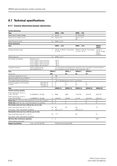
8.7 Technical specifications<br />
8.7.1 Control electronics/power electronics<br />
Control electronics<br />
Type <strong>3RW3</strong>. ..-1.B0. <strong>3RW3</strong>. ..-1.B1.<br />
Rated <strong>control</strong> supply voltage V UC 24 UC 110 to 230<br />
Rated <strong>control</strong> supply current mA Approx. 50 Approx. 25 to<br />
20<br />
Rated frequency at AC Hz 50/60 ± 10 %<br />
Power electronics<br />
Type <strong>3RW3</strong>. ..-1.B.4 <strong>3RW3</strong>. ..-1.B.5 <strong>3RW3</strong>0 ..-<br />
1AA12<br />
Voltage operating range V 200 AC to 460 AC, three-phase<br />
(± 10 %)<br />
Rated frequency Hz 50/60 ± 10 %<br />
Permissible site altitude<br />
Reduction of I E<br />
Up to 1000 m above sea level<br />
Up to 2000 m above sea level<br />
Up to 3000 m above sea level<br />
Up to 4000 m ab. sea level 1 )<br />
100 %<br />
92 %<br />
85 %<br />
78 %<br />
Installation position<br />
Without additional fan<br />
With additional fan 3 )<br />
460 AC to 575 AC, three phase<br />
(± 10 % - 15 %)<br />
115 AC to<br />
240 AC, singlephase<br />
(±10 %)<br />
The <strong>soft</strong> <strong>starter</strong>s are designed for operation when mounted in a vertical position.<br />
Any installation position (except vertical rotated by 180 °)<br />
Type<br />
Frame size<br />
<strong>3RW3</strong>0 1.<br />
S00<br />
<strong>3RW3</strong>. 2.<br />
S0<br />
<strong>3RW3</strong>0 3.<br />
S2<br />
Continuous operation (% of I e ) % 100<br />
Minimum load 2 ) (% of I e ); At 40 °C % 4<br />
Permissible ambient temperature °C –25 to +60 (derating as of 40 °C, see below)<br />
Switching capacity of the auxiliary<br />
contacts<br />
230 V/AC-15<br />
230 V/DC-13<br />
24 V/DC-13<br />
A<br />
A<br />
A<br />
4 )<br />
4 )<br />
4 )<br />
3<br />
0.1<br />
1<br />
3<br />
0.1<br />
1<br />
<strong>3RW3</strong>0 4.<br />
S3<br />
Type <strong>3RW3</strong>0 14 <strong>3RW3</strong>0 16 <strong>3RW3</strong>0 24 <strong>3RW3</strong>0 25 <strong>3RW3</strong>0 26<br />
Current-carrying capacity<br />
Rated operational current I e<br />
in acc. with IEC At 40/50/60 °C, AC-53b A 6/5/4 9/8/7 12.5/11/9 16/14/12 25/21/18<br />
Rated operational current I e<br />
in acc. with UL/CSA At 40/50/60 °C, AC-53b A 4.8/4.8/4 7.8/7.8/7 11/11/9 17.5/14/12 25/21/18<br />
Power loss at continuous rated operational current (40 °C) approx. W 5 7 7 9 13<br />
Power loss when the max. switching frequency is exploited W 5 6 7 8 9<br />
Permissible starts per hour without the use of a fan<br />
Given intermittent duty S4, T u = 40 °C 1/h 60 40 30 12<br />
Duty cycle = 30%; stand-alone installation % 250 x I e , 2 s 300 x I e , 2 s<br />
Permissible starts per hour with the use of a fan<br />
Given intermittent duty S4, T u = 40 °C<br />
Duty cycle = 30%; stand-alone installation<br />
1/h — 3 ) 54 21<br />
Idle time after continuous operation s 0 200<br />
With I e before a new start<br />
Degree of protection In acc. with IEC 60 529 IP20 (terminal housing IP00)<br />
3<br />
0.1<br />
1<br />
SIRIUS System Manual<br />
8-42 GWA 4NEB 430 0999-02c


