Hydrometers Operation and Maintenance Manual - Baseline Systems
Hydrometers Operation and Maintenance Manual - Baseline Systems
Hydrometers Operation and Maintenance Manual - Baseline Systems

Create successful ePaper yourself
Turn your PDF publications into a flip-book with our unique Google optimized e-Paper software.
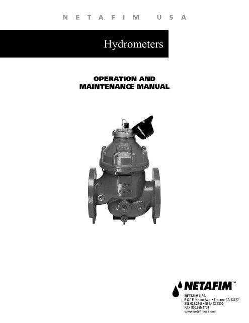
N E T A F I M U S A<br />
<strong>Hydrometers</strong><br />
OPERATION AND<br />
MAINTENANCE MANUAL<br />
NETAFIM USA<br />
5470 E. Home Ave. • Fresno, CA 93727<br />
888.638.2346 • 559.453.6800<br />
FAX 800.695.4753<br />
www.netafimusa.com
This manual is intended for use by the users of this equipment. The information<br />
contained herein is the property of Netafim USA <strong>and</strong> may not be copied, used, or<br />
disclosed to others without the manufacturer’s prior written approval.<br />
Users are cautioned that the material contained herein is subject to change by the<br />
manufacturer at any time <strong>and</strong> without prior notice. The material in this manual is<br />
intended for informational purposes only.
Table of Contents<br />
INTRODUCTION<br />
General Description .............................................................4<br />
Water Meter/Registers .........................................................4<br />
Hydraulic Valve (Flow Sensor) ...........................................4<br />
Specifications <strong>and</strong> Dimensions ............................................5<br />
Netafim USA <strong>Hydrometers</strong> with Electrical Output .............7<br />
Electrical Output Specifications (Reed Switch Reg.) ..........7<br />
Transducer Type ................................................................10<br />
Hydrometer Internal Components .....................................12<br />
INSTALLATION<br />
A. Installation Requirements..............................................13<br />
B. Unpacking .....................................................................13<br />
C. Pipeline Installation ......................................................13<br />
D. Preliminary Steps ..........................................................13<br />
E. Installing 1 ½” <strong>and</strong> 2” Models ......................................13<br />
F. Installing 3” – 8” Models ...............................................13<br />
CONTROL SYSTEM<br />
A. Solenoid Connection .....................................................14<br />
B. Electrical Output ...........................................................14<br />
DRAINAGE VALVE .......................................................15<br />
OPERATIONAL TESTING<br />
A. To test water flow <strong>and</strong> manual operation ......................16<br />
B. To test automatic <strong>and</strong> remote operation ........................16<br />
OPERATIONS<br />
A. <strong>Manual</strong> <strong>Operation</strong> .........................................................17<br />
B. Automatic <strong>Operation</strong> .....................................................17<br />
C. Solenoid <strong>Operation</strong> .......................................................17<br />
TYPICAL APPLICATIONS<br />
Pressure Sustaining ............................................................18<br />
Pressure Reducing .............................................................19<br />
TROUBLESHOOTING<br />
A. Leakage from Hydrometer Connection to Pipeline ......20<br />
B. No Electrical Output Signal from Hydrometer .............20<br />
C. Controller Indicates Water Not Flowing as Instructed ..20<br />
D. No Indication of Flow on Meter Dial ...........................20<br />
E. Controller Indicates Valve Opening Failure ..................21<br />
F. Controller Indicates Valve Closure Failure ....................21<br />
G. Leakage from Valves or Connectors .............................21<br />
H. Constant Drainage from Pilot Valve .............................21<br />
I. Excess or Insufficient Output Pressure ..........................22<br />
J. Excess or Insufficient Input Pressure .............................22<br />
K. Excess or Insufficient Flow Rate ..................................22<br />
MAINTENANCE PREPARATION<br />
Preliminary Steps ...............................................................23<br />
Tools ..................................................................................23<br />
MAINTENANCE 1 ½” – 8” HYDROMETERS<br />
Hydrometer Removal From Pipeline .................................24<br />
Finger Strainer Cleaning <strong>and</strong> Replacement .......................25<br />
Register Assembly Removal <strong>and</strong> Replacement .................25<br />
MAINTENANCE 1 ½” & 2” HYDROMETERS<br />
Hydrometer Cover <strong>and</strong> Base Assemblies ..........................26<br />
Diaphragm/Stem Dis-Assembly ........................................27<br />
Base <strong>and</strong> Stem Dis-Assembly ...........................................27<br />
Inlet Spider <strong>and</strong> Strainer ....................................................28<br />
MAINTENANCE 3” & 4” HYDROMETERS<br />
Hydrometer Dis-Assembly <strong>and</strong> Re-Assembly...................29<br />
Hydrometer Cover <strong>and</strong> Base Sub-Assemblies ..................29<br />
Diaphragm/Stem Assembly <strong>and</strong> Base Assembly ...............30<br />
Inlet Spider <strong>and</strong> Strainer ....................................................31<br />
MAINTENANCE 6” HYDROMETERS<br />
Hydrometer Dis-Assembly <strong>and</strong> Reinstallation ..................32<br />
Register ..............................................................................32<br />
Hydrometer Cover .............................................................32<br />
Diaphragm <strong>and</strong> Upper Stem Bearing ................................33<br />
Lower Stem Bearing <strong>and</strong> Valve Cover ..............................33<br />
Impeller <strong>and</strong> Flow Tube Sub-Assemblies ..........................34<br />
Inlet Spider ........................................................................34<br />
MAINTENANCE 8” HYDROMETER<br />
Hydrometer Dis-Assembly <strong>and</strong> Re-Assembly...................35<br />
Register ..............................................................................35<br />
Hydrometer Cover .............................................................35<br />
Diaphragm Sub-Assembly .................................................35<br />
Diaphragm Sub-Assembly <strong>and</strong> Dis-Assembly ..................36<br />
Lower Chamber Disc Sub-Assembly ................................36<br />
Stem Sub-Assembly <strong>and</strong> Valve Cover ...............................37<br />
Impellar <strong>and</strong> Flow Tube Assemblies .................................38<br />
Inlet Spider ........................................................................38<br />
SCHEMATICS .................................................................39
Introduction<br />
GENERAL DESCRIPTION<br />
A hydrometer combines a hydraulic master valve, water meter <strong>and</strong> a<br />
flow sensor in a single unit. Netafim USA’s Hydrometer is designed<br />
for high pressure, remote control irrigation <strong>and</strong> industrial applications.<br />
Body: Horizontal<br />
Available Sizes: 1½”, 2”, 3”, 4”, 6” <strong>and</strong> 8”<br />
<strong>Operation</strong>: For automatic <strong>and</strong> remote operation in a variety<br />
of applications. Remote operation is possible via<br />
an external solenoid valve activated by a remote<br />
controller or control center. Flow rate <strong>and</strong> volume<br />
data are electronically transmitted to the remote<br />
controller by means of a transducer inserted into<br />
the register dial.<br />
WATER METER/REGISTERS<br />
The hydrometer contains both a dry contact (reed switch) type<br />
magnetic drive <strong>and</strong> a higher frequency output photo-diode register<br />
transmission water meter, the impeller is the only moving part in<br />
contact with the water. The meter may be calibrated to measure either<br />
gallons or cubic meters. A hermetically sealed register contains the<br />
dial face <strong>and</strong> all mechanical meter components.<br />
Totalizer<br />
Rotating Flow<br />
Indicator or<br />
Leak Detector<br />
The dial face contains:<br />
• Totalizer<br />
• Three (3) analog pointers<br />
• Rotating flow indicator or leak detector<br />
A magnetic pointer, located over one of the analog pointers, measures<br />
the flow rate <strong>and</strong> transmits the data to the reed switch transducer in<br />
the register cover.<br />
St<strong>and</strong>ard Register<br />
Gallon<br />
Gallon Totalizer<br />
Totalizer<br />
Analog Pointers<br />
HYDRAULIC VALVE (FLOW SENSOR)<br />
The hydrometer contains a hydraulic master valve operated either<br />
manually or by remote control. The valve normally remains closed<br />
until a comm<strong>and</strong> is received to open it. Hydraulic comm<strong>and</strong>s<br />
are transmitted to the valve via an external solenoid valve. The<br />
hydrometer can also be ordered in a Normally Open configuration.<br />
In this case the valve is opened until a comm<strong>and</strong> is received <strong>and</strong> the<br />
valve closes.<br />
4 • <strong>Hydrometers</strong> <strong>Operation</strong> <strong>and</strong> <strong>Maintenance</strong> <strong>Manual</strong>
Specifications <strong>and</strong> Dimensions<br />
SPECIFICATIONS<br />
Size 1 ½” 2” 3” 4” 6” 8”<br />
Maximum Working Pressure (psi) 230 230 230 230 230 230<br />
Minimum Working Pressure (psi) 14 14 14 14 14 14<br />
Regulated Pressure Ratio 1:3 1:3 1:3 1:3 1:3 1:3<br />
Maximum Flow Rate (GPM) 55 95 220 380 860 1500<br />
Minimum Flow Rate (GPM) 4.4 20 53 79 198 357<br />
Accuracy ±2% ±2% ±2% ±2% ±2% ±2%<br />
H<br />
W<br />
L<br />
W<br />
H<br />
H<br />
W L<br />
W L<br />
Hydrometer Dimensions<br />
Size 1 ½” 2” 3” 4” 6” 8”<br />
Length (L) 6 5 /16” 6 1 /4” 9 9 /16” 10 15 /16” 19 1 /2” 20 11 /16”<br />
Width (W) 4 3 /4” 4 3 /4” 8 1 /4” 9 1 /16” 14 7 /8” 17 3 /4”<br />
Height (H) 10 5 /16” 13 13 /16” 16 15 /16” 17 3 /4” 25 7 /16” 25 5 /8”<br />
Weight 4 lbs. 7 lbs. 52 lbs. 65 lbs. 245 lbs. 309 lbs.<br />
<strong>Hydrometers</strong> <strong>Operation</strong> <strong>and</strong> <strong>Maintenance</strong> <strong>Manual</strong> • 5
Specifications, Cont.<br />
Headloss Charts<br />
5.0<br />
1 ½”<br />
5.0<br />
4.0<br />
4.0<br />
6”<br />
Headloss (psi)<br />
3.0<br />
2.0<br />
2”<br />
3”<br />
Headloss (psi)<br />
3.0<br />
2.0<br />
4”<br />
8”<br />
1.0<br />
1.0<br />
0 50 100 150 200 250<br />
Flow Rate (gpm)<br />
0 200 400 600 800 1000 1200 1400<br />
Flow Rate (gpm)<br />
Pressure loss in psi = (gpm/Cv)^2<br />
Example: 2” Hydrometer, design flow @ 97 gpm<br />
(55 gpm/35 gpm)^2 = 2.5 psi headloss<br />
Performance Data<br />
Cv Values<br />
Lowest Flow<br />
within ± 5% Accuracy<br />
Lowest Flow<br />
within ± 2% Accuracy<br />
Nominal Flow<br />
within ± 2% Accuracy<br />
Maximum Flow<br />
within ± 2% Accuracy<br />
Cv (Flow Rate at<br />
1.0 psi of Headloss)<br />
Size<br />
1 ½”<br />
2”<br />
3”<br />
4”<br />
6”<br />
8”<br />
1.8 GPM 4.4 GPM 44 GPM 55 GPM<br />
5.3 GPM 20 GPM 66 GPM 95 GPM<br />
14 GPM 53 GPM 176 GPM 220 GPM<br />
21 GPM 79 GPM 264 GPM 380 GPM<br />
53 GPM 198 GPM 660 GPM 860 GPM<br />
97 GPM 357 GPM 1,189 GPM 1,500 GPM<br />
Size<br />
1 ½”<br />
2”<br />
3”<br />
4”<br />
6”<br />
8”<br />
23 GPM<br />
35 GPM<br />
92 GPM<br />
139 GPM<br />
347 GPM<br />
624 GPM<br />
6 • <strong>Hydrometers</strong> <strong>Operation</strong> <strong>and</strong> <strong>Maintenance</strong> <strong>Manual</strong>
Specifications, Cont.<br />
NETAFIM USA HYDROMETERS WITH ELECTRICAL OUTPUT<br />
Netafim USA <strong>Hydrometers</strong> are equipped with electrical output devices that combine the high reliability<br />
of hermetically sealed, magnetically driven registers with a wide variety of electrical output options.<br />
<strong>Hydrometers</strong> (measuring instruments) provide electrical output information about the flow of water.<br />
When more than just the traditional register is needed, they also provide the solution for automation <strong>and</strong><br />
communication with controllers, electronic devices <strong>and</strong> other water delivery systems.<br />
Netafim USA has three types of transducer outputs available which provide three levels of resolution:<br />
• Reed Switch (RS) Register - low frequency pulse output for functions related<br />
primarily to recording volume.<br />
• Photo Diode (PD) Register - st<strong>and</strong>ard frequency pulse output (open collector) for<br />
functions such as rate of flow <strong>and</strong> recording total volume.<br />
• Photo Diode (PDH) Register - high frequency pulse (open collector) for functions<br />
such as rate of flow <strong>and</strong> recording total volume.<br />
Recommended Register<br />
Transducer Outputs<br />
Manufacturer<br />
Controller<br />
Model<br />
Recommended<br />
Register Type<br />
<strong>Baseline</strong> Basestation PDH<br />
Hunter ACC 2-Wire PDH<br />
Rain Bird MDC & Maxi RS<br />
Signature All Models RS<br />
Toro<br />
Sentinel<br />
PDH<br />
TDC 2-Wire PDH<br />
Rainmaster All Models<br />
RS (1” to 4”)<br />
PD (6”, 8”)<br />
Tucor<br />
Flowmaster<br />
& RK Series PDH<br />
Motorola All Models RS<br />
ELECTRICAL OUTPUT SPECIFICATIONS<br />
REED SWITCH (RS) REGISTER<br />
The flow rate is transmitted as periodic electrical pulses are measured by the magnetic pointer in<br />
the dial face. The hydrometer is configured to transmit a pulse according to a pre-defined volume<br />
interval. The following summarizes the available volume intervals for various hydrometer sizes in<br />
either gallons or cubic meters.<br />
• A three pointer register, with a magnet installed on one of the pointers.<br />
• Output definition: Volume Output<br />
• Output type: RS – Reed Switch <strong>and</strong> PD – Photo Diode<br />
The sensor is installed in a transparent plastic cover that can be mounted on the register in one of<br />
three positions with the pointer facing the magnet. Three values of electrical output are available<br />
in 1:10:100 ratios.<br />
<strong>Hydrometers</strong> <strong>Operation</strong> <strong>and</strong> <strong>Maintenance</strong> <strong>Manual</strong> • 7
Specifications, Cont.<br />
U.S. GALLONS<br />
0 0 0 0 0 0<br />
U.S. GALLONS<br />
0 0 0 0 0 0<br />
x 1000<br />
BM<br />
BM<br />
Pulse per<br />
1 USG<br />
0<br />
0<br />
9<br />
1<br />
9<br />
1<br />
8<br />
8<br />
2<br />
2<br />
7<br />
0<br />
3 9<br />
7<br />
1<br />
3<br />
6<br />
4 8<br />
6<br />
4<br />
5<br />
2 5<br />
7<br />
3<br />
6<br />
4<br />
5<br />
Pulse per<br />
100 USG<br />
Pulse per<br />
10 USG<br />
0<br />
0<br />
9<br />
1<br />
9<br />
1<br />
8<br />
8<br />
2<br />
2<br />
7<br />
0<br />
3 9<br />
7<br />
1<br />
3<br />
6<br />
4 8<br />
6<br />
4<br />
5<br />
2 5<br />
7<br />
3<br />
6<br />
4<br />
5<br />
Pulse per<br />
1000 USG<br />
Pulse per<br />
10 USG<br />
Pulse per<br />
100 USG<br />
EXAMPLE for sizes 1½”, 2”, 3”, 4”<br />
(st<strong>and</strong>ard pulse = 1 g/p)<br />
Available Impulse Sequences<br />
Available Outputs<br />
(U.S. gallons/pulse) 1 ½” 2”<br />
1 <br />
3” 4” 6” 8”<br />
10 <br />
100 <br />
1000 <br />
EXAMPLE for sizes 6”, 8”<br />
(st<strong>and</strong>ard pulse = 10 g/p)<br />
For sizes 1½”, 2”, 3”, 4”: If the pointer with the magnet is set in the middle position as shown<br />
in the drawing the magnet will make one contact of the reed switch for every 360° rotation - the<br />
result is an output of 1 pulse per 10 USG.<br />
For sizes 6”, 8”: If the pointer with the magnet is set in the right position as shown in the drawing<br />
the magnet will make one contact of the reed switch for every 360° rotation - the result is an<br />
output of 1 pulse per 1000 USG.<br />
Reed Switch (RS) Register<br />
Specifications<br />
• Magnet activated.<br />
• Acts as a “dry contact”, uses very little<br />
electric power.<br />
• For “Volume” related functions such as<br />
data recorders or simple counters.<br />
Circuit Diagram<br />
Register with Reed Switch<br />
Output, Two Wires<br />
Electrical Specifications<br />
Maximum Contact Current: 50 mA<br />
Maximum Contact Voltage: 28 VDC<br />
Reed Switch (RS)<br />
Low Frequency Pulse Outputs<br />
Hydrometer<br />
Size<br />
Gallons/<br />
Pulse<br />
Reed Switch (RS)<br />
Pulse/<br />
Gallon K Factor Offset<br />
1½”, 2”, 3”, 4” 1 1 60.00 0<br />
6”, 8” 10 0.1 600.00 0<br />
8 • <strong>Hydrometers</strong> <strong>Operation</strong> <strong>and</strong> <strong>Maintenance</strong> <strong>Manual</strong>
Specifications, Cont.<br />
Photo-Diode (PD & PDH) Register<br />
• Sensor combines an IR light source <strong>and</strong> a light sensitive<br />
diode in one package.<br />
• Signals are created when the light beam created by the<br />
IR light is interrupted by a rotating element.<br />
• Requires a constant supply of DC power.<br />
Circuit Diagram<br />
Register with Photo Diode<br />
Output <strong>and</strong> Wire Leads<br />
Note: Sunlight will interfere<br />
with the IR light <strong>and</strong> may<br />
corrupt or interfere with the<br />
signal—keep dust cap closed<br />
during operation to ensure<br />
proper signal output.<br />
Photo-Diode Electrical<br />
Specifications<br />
POSITIVE powers the IR light<br />
(yellow wire)<br />
Current Min: 15 mA to a maximum of 25 mA DC<br />
through a resistor<br />
• Maximum Voltage: 28 VDC<br />
OUTPUT (clear wire)<br />
Output – Open collector<br />
(Max. Load – 2 mA)<br />
GROUND (bare wire)<br />
Recommended<br />
Resistor Valves<br />
Resistor Values<br />
Voltage (V+) Ω W<br />
5 180 0.25<br />
6 220 0.25<br />
9 330 0.25<br />
12 470 0.50<br />
24 1000 1.00<br />
NOTE: Correct polarity of the leads should be<br />
checked carefully to prevent damage to<br />
the sensor.<br />
<strong>Hydrometers</strong> <strong>Operation</strong> <strong>and</strong> <strong>Maintenance</strong> <strong>Manual</strong> • 9
Transducer Type<br />
Transducer Type: Reed Switch <strong>and</strong> Photo Diode K Factors<br />
Meter<br />
Size<br />
1½”<br />
2”<br />
3”<br />
4”<br />
6”<br />
8”<br />
Reed Switch (RS)<br />
Photo Diode (PD) <strong>and</strong><br />
Photo Diode High Frequency<br />
Pulse (PDH)<br />
St<strong>and</strong>ard<br />
Output Optional Output PD PDH<br />
Gallons per pulse 1 10 100 0.1 0.0053<br />
Pulse per gallon 1 0.1 0.01 10 187.900<br />
K factor 10.00 60.00 600.00 6000.00 6.00 0.319<br />
Gallons per pulse 1 10 100 0.1 0.0085<br />
Pulse per gallon 1 0.1 0.01 10 117.000<br />
K factor 10.00 60.00 600.00 6000.00 6.00 0.5100<br />
Gallons per pulse 1 10 100 0.1 0.0205<br />
Pulse per gallon 1 0.1 0.01 10 48.710<br />
K factor 10.00 60.00 600.00 6000.00 6.00 1.232<br />
Gallons per pulse 1 10 100 1 0.0556<br />
Pulse per gallon 1 0.1 0.01 10 17.993<br />
K factor 10.00 60.00 600.00 6000.00 6.00 3.335<br />
Gallons per pulse 10 100 1000 1 0.1741<br />
Pulse per gallon 0.1 0.01 0.001 1 5.747<br />
K factor 10.00 600.00 6000.00 60000.00 60.00 10.437<br />
Gallons per pulse 10 100 1000 1 0.317<br />
Pulse per gallon 0.1 0.01 0.001 1 3.152<br />
K factor 10.00 600.00 6000.00 60000.00 60.00 19.036<br />
Note: Offset = 0 in all Netafim USA Water Meters<br />
When entering K factors in controllers <strong>and</strong>/or data recorders please refer to the manufacturer’s<br />
recommendations—some will require the number of gallons per pulse <strong>and</strong> others will require<br />
the number of pulses per gallon. Some manufacturers will require a “K” <strong>and</strong> “offset” (for all<br />
Netafim USA Water Meters the offset = 0) where the K <strong>and</strong> offset are calculated using he following<br />
equation:<br />
Freq = (GPM/K) – offset<br />
Where:<br />
Freq = pulse/second<br />
GPM = gallons per minute<br />
K = unit less constant specific to each hydrometer pulse output<br />
Offset = correction factor (All Netafim USA water meters have an offset = 0)<br />
or:<br />
K<br />
= 60/(pulse/gallon)<br />
10 • <strong>Hydrometers</strong> <strong>Operation</strong> <strong>and</strong> <strong>Maintenance</strong> <strong>Manual</strong>
Specifications, Cont.<br />
Ordering Information<br />
FLOW RANGE<br />
Min GPM<br />
± 5%<br />
Max GPM<br />
± 2%<br />
Meter<br />
Size<br />
Connection<br />
Register<br />
Output<br />
Type<br />
Pulse per<br />
Galon<br />
Gallons<br />
per Pulse<br />
PD 10 0.1<br />
1.8 55 1½” Male Pipe Thread PDH 187.900 0.0053<br />
RS 1 1<br />
PD 10 0.1<br />
5.3 95 2” Female Pipe Thread PDH 117.000 0.0085<br />
RS 1 1<br />
PD 10 0.1<br />
14 220 3” Flanged PDH 48.710 0.0205<br />
RS 1 1<br />
PD 10 0.1<br />
21 380 4” Flanged PDH 17.933 0.0556<br />
RS 1 1<br />
PD 1 1<br />
53 860 6” Flanged PDH 5.747 0.1741<br />
RS 0.1 10<br />
PD 1 1<br />
97 1,500 8” Flanged PDH 3.152 0.317<br />
RS 0.1 10<br />
Electric<br />
Pressure<br />
Regulating<br />
Model Number<br />
• LHM15TG01-MEL<br />
• • LHM15TG01-PRMEL<br />
• LHM15TG0053-MEL<br />
• • LHM15TG0053-PRMEL<br />
• LHM15TG1-MEL<br />
• • LHM15TG1-PRMEL<br />
• LHM2TG01-MEL<br />
• • LHM2TG01-PRMEL<br />
• LHM2TG0085-MEL<br />
• • LHM2TG0085-PRMEL<br />
• LHM2TG1-MEL<br />
• • LHM2TG1-PRMEL<br />
• LHM3FG01-MEL<br />
• • LHM3FG01-PRMEL<br />
• LHM3FG0205-MEL<br />
• • LHM3FG0205-PRMEL<br />
• LHM3FG1-MEL<br />
• • LHM3FG1-PRMEL<br />
• LHM4FG01-MEL<br />
• • LHM4FG01-PRMEL<br />
• LHM4FG0556-MEL<br />
• • LHM4FG0556-PRMEL<br />
• LHM4FG1-MEL<br />
• • LHM4FG1-PRMEL<br />
• LHM6FG1-MEL<br />
• • LHM6FG1-PRMEL<br />
• LHM6FG1739-MEL<br />
• • LHM6FG1739-PRMEL<br />
• LHM6FG10-MEL<br />
• • LHM6FG10-PRMEL<br />
• LHM8FG1-MEL<br />
• • LHM8FG1-PRMEL<br />
• LHM8FG317-MEL<br />
• • LHM8FG317-PRMEL<br />
• LHM8FG10-MEL<br />
• • LHM8FG10-PRMEL<br />
Netafim <strong>Hydrometers</strong> are st<strong>and</strong>ard in a manually closed configuration. To order Normally Open (NO)<br />
configurations add -NO to the end of the model number.<br />
For example: When ordering a 8” Flanged Photo-Diode (PD) Normally Open Hydrometer,<br />
use Model Number LHM8FG1-MEL-NO<br />
<strong>Hydrometers</strong> <strong>Operation</strong> <strong>and</strong> <strong>Maintenance</strong> <strong>Manual</strong> • 11
Hydrometer Internal Components<br />
Hydrometer Internal Components<br />
(Double Chamber Not Available in 6”)<br />
12 • <strong>Hydrometers</strong> <strong>Operation</strong> <strong>and</strong> <strong>Maintenance</strong> <strong>Manual</strong>
Installation<br />
A. Installation Requirements<br />
• Globe configuration hydrometers<br />
require no straight pipe installation<br />
requirements. Do not install valves<br />
that will cause a restriction directly<br />
upstream or downstream of the<br />
hydrometer.<br />
• Connections to the hydrometer<br />
should be the same size as the meter.<br />
Example: if a 3” hydrometer is<br />
installed, 3” pipe <strong>and</strong> fittings should<br />
be connected to the hydrometer.<br />
• Prior to installation of the meter, the<br />
pipeline should be thoroughly flushed.<br />
• Recommendation: Air Vents of proper size <strong>and</strong> type, Continuous<br />
acting <strong>and</strong> large acting, be installed to eliminate air.<br />
B. Unpacking<br />
The hydrometer comes fully assembled according to the customer’s specifications. The 1½” model<br />
is shipped with the appropriate couplings <strong>and</strong> gaskets. For larger diameter models installation<br />
hardware is not included for larger diameter models. Pilot valves <strong>and</strong> other accessories are factory<br />
installed <strong>and</strong> calibrated according to the customer’s specifications.<br />
C. Pipeline Installation<br />
The following tools are required to perform these procedures:<br />
• Flat blade <strong>and</strong> Phillips head screwdrivers in various sizes<br />
• Open end or box wrenches in various sizes<br />
• Large pipe wrenches<br />
• Pliers<br />
• Dies or pipe threading tools compatible with the pipeline diameter<br />
• Teflon tape or similar pipe sealing material<br />
D. Preliminary Steps<br />
1. Before beginning the installation, the line should be thoroughly flushed to remove any<br />
foreign matter.<br />
2. Close the inlet valve in order to shut off the water flow to the pipeline.<br />
E. Installing 1½” <strong>and</strong> 2” Models<br />
The 2” hydrometer can be attached directly to a male threaded pipeline or to a female threaded<br />
pipeline using a coupling. The 1½” model can only be attached using a coupling.<br />
Coupling Connection<br />
• Create a female threaded connection on both pipe sections.<br />
• Apply Teflon tape or similar material to seal the connections.<br />
• Insert the male coupling connections into the pipeline sections <strong>and</strong> tighten securely.<br />
• Place a coupling gasket over each male threaded hydrometer connection <strong>and</strong><br />
securely tighten the coupling nuts.<br />
Direct Connection<br />
• Create a male threaded connection on both pipe sections that are to be attached.<br />
• Apply Teflon tape or similar material to seal the connections.<br />
• Insert the male threaded pipe connection into the hydrometer <strong>and</strong> tighten securely.<br />
F. Installing 3” – 8” Models<br />
The end user is expected to supply the appropriate gaskets<br />
<strong>and</strong> bolts according to the diameter of the pipeline.<br />
• Place the appropriate gasket onto each flange.<br />
• Insert the bolts, nuts <strong>and</strong> washers <strong>and</strong> tighten securely.<br />
Globe Configuration<br />
Straight Pipe Installation Requirement<br />
0 x D <strong>and</strong> 0 x D<br />
Size<br />
Upstream<br />
Distance<br />
Downstream<br />
Distance<br />
Meter<br />
Length<br />
Total<br />
Requirement<br />
1 ½” 0” 0” 6 5 /16” 6 5 /16”<br />
2” 0” 0” 8 5 /8” 8 5 /8”<br />
3” 0” 0” 11 1 /2” 11 1 /2”<br />
4” 0“ 0” 14 1 /8“ 14 1 /8“<br />
6” 0“ 0” 19 1 /2“ 19 1 /2“<br />
8” 0” 0” 23 5 /8“ 23 5 /8“<br />
<strong>Hydrometers</strong> <strong>Operation</strong> <strong>and</strong> <strong>Maintenance</strong> <strong>Manual</strong> • 13
Installation, Cont.<br />
CONTROL SYSTEM<br />
A. Solenoid Connection<br />
The hydrometer receives comm<strong>and</strong>s from the controller or control center via an external solenoid<br />
valve. The hydrometer may be ordered with a factory installed solenoid valve or connected to an<br />
solenoid valve supplied by the user.<br />
To connect to a factory installed solenoid:<br />
1. Connect the electric cable from controller to the attached solenoid valve. Position<br />
the three-way selector in the “Auto” position - in this position the hydrometer will be<br />
controlled by the solenoid.<br />
B. Electrical Output<br />
The hydrometer supplies volume <strong>and</strong> flow rate data to a controller or to an external measuring<br />
device via an electrical connection. A reed switch transducer is factory installed in the register<br />
dial. The cable attached to the reed switch transducer attaches to the controller or measuring<br />
device.<br />
To connect the hydrometer to the controller or measuring device:<br />
1. Install an appropriate connector onto the bare end of the cable exiting from the reed<br />
switch. Refer to the user manual of the controller or measuring device for details<br />
regarding the specific connector type.<br />
2. Connect the cable to the input port of the controller or measuring device.<br />
(See pages 7-10 for more details)<br />
14 • <strong>Hydrometers</strong> <strong>Operation</strong> <strong>and</strong> <strong>Maintenance</strong> <strong>Manual</strong>
Drainage Valve<br />
DRAINAGE VALVE<br />
At the beginning of the winter it is necessary to drain the water from the pipeline in order to<br />
prevent the pipes from bursting. (Please refer to the drawing below)<br />
• Before draining, it is very important to ensure that there is no pressure in the line.<br />
• Dissassemble plug (1)<br />
• Assemble the drainage ball valve (2)<br />
• Assemble elbow (3)<br />
CAUTION: Do not use compressed air to blow out hydrometer.<br />
<strong>Hydrometers</strong> <strong>Operation</strong> <strong>and</strong> <strong>Maintenance</strong> <strong>Manual</strong> • 15
<strong>Operation</strong>al Testing<br />
INSTALLATION<br />
Before the hydrometer is placed into service, you should perform the following tests to verify that<br />
it is operating properly:<br />
A. To test water flow <strong>and</strong> manual operation:<br />
• Set 3-Way Selector to the “Open position”.<br />
• Turn on the water flow to the hydrometer.<br />
• Visually verify that water is flowing downstream from the hydrometer in appropriate<br />
quantities.<br />
• Verify that the leak detector, pointers <strong>and</strong> the totalizer are functioning properly.<br />
• Check all hoses, connections, pilot valves, etc. for leakage <strong>and</strong> repair as necessary.<br />
• Set 3-Way Selector to the “Close position”.<br />
• Verify that the water flow downstream has stopped.<br />
B. To test automatic <strong>and</strong> remote operation:<br />
• Set 3-Way Selector to the “Auto” position.<br />
• Turn on the water flow to hydrometer.<br />
• Verify that the hydrometer output is correctly received by the controller or control center.<br />
• Use the controller or control center to close the hydrometer. Verify that the water flow<br />
downstream has stopped.<br />
• Use the controller software to test operation of the hydrometer under various applications<br />
<strong>and</strong> conditions such as pressure reducing, pressure sustaining <strong>and</strong> flow regulation.<br />
• Your hydrometer is now ready for routine use.<br />
16 • <strong>Hydrometers</strong> <strong>Operation</strong> <strong>and</strong> <strong>Maintenance</strong> <strong>Manual</strong>
<strong>Operation</strong>s<br />
The hydrometer is designed to operate in a variety of automatic <strong>and</strong> remote control applications.<br />
The hydrometer valve is also capable of manual operation <strong>and</strong> the register dial may be read as an<br />
ordinary water meter.<br />
A. <strong>Manual</strong> <strong>Operation</strong><br />
The hydrometer may be manually operated using the 3-Way Selector:<br />
• To manually open the valve: Rotate the 3-Way Selector to the “Open” position.<br />
• To manually close the valve: Rotate the 3-Way Selector to the “Close” position.<br />
3-Way Selector<br />
B. Automatic <strong>Operation</strong><br />
Automatic operation is made possible by direct hydraulic control from a remote controller or<br />
control center. Volume <strong>and</strong>/or flow data is electronically transmitted to the remote controller<br />
by means of a reed switch transducer. The comm<strong>and</strong> to open or close the hydrometer valve is<br />
transmitted from the controller to a solenoid, which, in turn, transmits a hydraulic comm<strong>and</strong> to the<br />
hydrometer.<br />
Automatic operation may also be based on a pre-set pressure or flow rate by the use of one or<br />
more Pilot Valves. To enable automatic <strong>and</strong>/or remote operation, rotate the 3-Way Selector to the<br />
“Auto” position.<br />
C. Solenoid <strong>Operation</strong><br />
SOLENOID<br />
The hydrometer is always controlled via an external solenoid valve. A “normally open” (NO),<br />
high pressure, 3-Way solenoid valve is required for this purpose resulting in a normally closed<br />
hydrometer. When a normally closed solenoid is used it will result in a normally open hydrometer.<br />
An electric cable connects the controller <strong>and</strong> the solenoid valve. 8 mm polyethylene tubing runs<br />
from the solenoid valve to the “Auto” connection on the 3-Way Selector.<br />
SOLENOID<br />
SOLENOID<br />
Automatic<br />
Position<br />
Open<br />
Position<br />
Automatic Position<br />
Operated by the Controller<br />
Open<br />
<strong>Manual</strong> Override<br />
SOLENOID<br />
Electric Solenoid Specifications<br />
• <strong>Operation</strong>:<br />
– Solenoid: 24vac 5.5 watts,<br />
0.23 amps inrush<br />
– <strong>Manual</strong> Override<br />
• Construction: Brass<br />
• Connections: In/Out NPT Threaded<br />
<strong>Hydrometers</strong> <strong>Operation</strong> <strong>and</strong> <strong>Maintenance</strong> <strong>Manual</strong> • 17
Typical Applications<br />
PRESSURE SUSTAINING<br />
The pressure sustaining operation prevents the input pressure from falling below a predetermined<br />
value. This application requires a Netafim Pressure Regulating Pilot Valve, or comparable valve.<br />
Rotate the adjusting screw atop the pilot valve counterclockwise to increase the desired input<br />
pressure <strong>and</strong> clockwise to reduce the desired input pressure.<br />
Connection Information<br />
The sensor connection runs from the input connector on the hydrometer to the controlled input<br />
connector (1) on the pilot valve. The sensor connection also branches off to the “Close” connector<br />
on the 3-Way Selector <strong>and</strong> to the vent connector (4) on the pilot valve.<br />
The comm<strong>and</strong> connection runs from solenoid to the “Auto” connector on the 3-Way Selector<br />
(via the shuttle valve) <strong>and</strong> continues on to the pressure controlled input connector (2) on the pilot<br />
valve.<br />
The supply connector (3) on the pilot valve serves as a vent. The output connector on the<br />
hydrometer is not used.<br />
18 • <strong>Hydrometers</strong> <strong>Operation</strong> <strong>and</strong> <strong>Maintenance</strong> <strong>Manual</strong>
Typical Applications, Cont.<br />
PRESSURE REDUCING<br />
The pressure reducing operation prevents the output pressure from increasing above a<br />
predetermined value. This application requires a PC Pressure Regulating Pilot Valve, or<br />
comparable valve. Rotate the adjusting screw on top of the pilot valve counterclockwise to<br />
increase the desired output pressure <strong>and</strong> clockwise to reduce the desired output pressure.<br />
Connection Information<br />
The sensor connection runs from the output connector on the hydrometer to the pilot valve<br />
controlled input connector (1).<br />
The pressure supply connection runs from the hydrometer input connection to the pilot valve<br />
supply connector (3). This connection branches off to the “Close” connection on the 3-Way<br />
Selector.<br />
The comm<strong>and</strong> connection runs from solenoid to the “Auto” connector on the 3-Way Selector <strong>and</strong><br />
continues on to the pressure controlled input connector (2) on the pilot valve.<br />
The vent connector (4) on the pilot valve serves as a vent.<br />
<strong>Hydrometers</strong> <strong>Operation</strong> <strong>and</strong> <strong>Maintenance</strong> <strong>Manual</strong> • 19
Troubleshooting<br />
This chapter provides detailed troubleshooting procedures <strong>and</strong> solutions for a variety of<br />
common problems. The procedures described below are general in nature <strong>and</strong> are presented in<br />
a “Quick Reference” style outline format.<br />
We recommend that you perform the steps in order until the specific problem is solved. It may<br />
not be necessary to complete all of the steps in a given procedure.<br />
A. Leakage from Hydrometer Connection to Pipeline<br />
• Inspect <strong>and</strong> tighten the couplings or flange bolts. Replace the coupling, bolts <strong>and</strong> nuts<br />
as necessary.<br />
• Apply Teflon tape, or other similar material, to seal the connection.<br />
• Inspect <strong>and</strong> replace gaskets as necessary.<br />
• Inspect <strong>and</strong> clean the orifice <strong>and</strong> associated gaskets (flow control applications only).<br />
Replace as necessary.<br />
B. No Electrical Output Signal From Hydrometer<br />
• Inspect all cables <strong>and</strong> electrical connections. Repair or replace cables as necessary.<br />
• Verify that the reed switch transducer is properly inserted into the register dial.<br />
• Verify that the controller is functioning properly. If not, restart the controller <strong>and</strong> make<br />
certain that your software is properly configured.<br />
• Replace the reed switch transducer.<br />
• Verify that the flow indicator on the meter dial is rotating.<br />
C. The Controller Indicates Water is Not Flowing as Instructed<br />
• Verify that the controller is functioning properly. If not, restart the controller <strong>and</strong> verify<br />
that your software is properly configured.<br />
• Move the 3-Way Selector to the “Open” position. Check to see if the controller shows<br />
water flow. If so, this indicates that the solenoid is not functioning properly. Repair or<br />
replace as necessary.<br />
• Verify that the reed switch transducer is properly inserted into the register dial.<br />
• Check all electrical connections. Replace cables as necessary.<br />
• Verify that the flow indicator on the meter dial is rotating.<br />
D. No Indication of Flow on Meter Dial<br />
• Remove the register assembly as described on page 25. Place a small magnet on the<br />
bottom of the register assembly <strong>and</strong> move it in a circular motion. This should cause the<br />
flow indicator to rotate freely. If it does not, replace the register.<br />
• Disassemble the hydrometer as described in Chapter 5.<br />
• Clean or replace the strainer (1½” <strong>and</strong> 2” models only).<br />
• Verify that the impeller rotates freely. If it does not, inspect the impeller, impeller shaft<br />
<strong>and</strong> other related components. Replace as necessary.<br />
• Inspect the diaphragm <strong>and</strong> o-rings. Replace as necessary.<br />
20 • <strong>Hydrometers</strong> <strong>Operation</strong> <strong>and</strong> <strong>Maintenance</strong> <strong>Manual</strong>
Troubleshooting, Cont.<br />
E. Controller Indicates Valve Opening Failure<br />
• Verify that the 3-Way Selector is in the “Auto” position. If it is not, turn the switch to the<br />
“Auto” position <strong>and</strong> then check to see if the controller indicates that the valve is open.<br />
• Verify that the controller <strong>and</strong> your software are functioning properly. If not, restart the<br />
controller <strong>and</strong> make certain that your software is properly configured.<br />
• Verify if there is water flow downstream from the hydrometer. If there is not, this indicates<br />
that the valve is indeed closed.<br />
• Check the electrical connections as described on page 8.<br />
• Check the register as described in the first step on page 5.<br />
• Remove the 3-Way Selector. Clean or replace as necessary.<br />
• Verify solenoid operation. Repair or replace as necessary.<br />
• Disassemble the hydrometer as described in the <strong>Maintenance</strong> section, pages 23-38.<br />
• Clean or replace the strainer (1½” <strong>and</strong> 2” models only).<br />
• Inspect the diaphragm <strong>and</strong> o-rings. Replace as necessary.<br />
F. Controller Indicates Valve Closure Failure<br />
• Verify that the 3-Way Selector is in the “Auto” position. If it is not, turn the switch to the<br />
“Auto” position <strong>and</strong> then check to see if the controller indicates that the valve is open.<br />
• Verify that the controller <strong>and</strong> your software are functioning properly. If not, restart the<br />
controller <strong>and</strong> make certain that your software is properly configured.<br />
• Move the 3-Way Selector to the “Close” position. Check to see if the controller indicates<br />
that the valve is closed. If so, this indicates that the solenoid is not functioning properly.<br />
Repair or replace as necessary.<br />
• Verify if there is water flow downstream from the hydrometer. If there is, this indicates that<br />
the valve is indeed open.<br />
• Check the electrical connections as described on page 7.<br />
• Check the register as described in the first step on page 4.<br />
• Remove the 3-Way Selector. Clean or replace as necessary.<br />
• Remove <strong>and</strong> clean the finger strainer. Replace if necessary.<br />
• Disassemble the hydrometer as described in the <strong>Maintenance</strong> section, pages 22-37.<br />
• Inspect the diaphragm, valve cover <strong>and</strong> o-rings. Replace as necessary.<br />
G. Leakage from Valves or Connectors<br />
• Inspect the control hoses, connectors, shuttle valves <strong>and</strong> adapters. Tighten <strong>and</strong> replace as<br />
necessary.<br />
H. Constant Drainage from Pilot Valve<br />
• Repair or replace the pilot valve.<br />
<strong>Hydrometers</strong> <strong>Operation</strong> <strong>and</strong> <strong>Maintenance</strong> <strong>Manual</strong> • 21
Troubleshooting, Cont.<br />
I. Excess or Insufficient Output Pressure<br />
• Inspect the control hoses, connectors, shuttle valves <strong>and</strong><br />
adapters. Replace as necessary.<br />
• Rotate the adjustment screw atop of the pilot valve. Rotate<br />
clockwise to increase pressure or counterclockwise to reduce<br />
pressure as necessary.<br />
• Remove <strong>and</strong> clean the finger strainer. Replace if necessary.<br />
• If this fails to balance the pressure, try the following procedure:<br />
- Unscrew <strong>and</strong> remove the throttle housing (12) at the<br />
bottom of the pilot valve.<br />
- Remove the throttle pin (14) from inside the housing.<br />
- Wrap the throttle pin (14) with Teflon tape <strong>and</strong> re-insert<br />
it into the housing.<br />
- Re-insert <strong>and</strong> tighten the throttle housing into the pilot<br />
• Replace the pilot valve.<br />
J. Excess or Insufficient Input Pressure<br />
• Inspect the control hoses, connectors, shuttle valves <strong>and</strong> adapters. Tighten <strong>and</strong> replace as<br />
necessary.<br />
• Remove <strong>and</strong> clean the finger strainer. Replace if necessary.<br />
• Repair or replace the pilot valve.<br />
K. Excess or Insufficient Flow Rate<br />
• Inspect the control hoses, connectors, shuttle valves <strong>and</strong><br />
adapters.<br />
• Tighten <strong>and</strong> replace as necessary.<br />
• Rotate the adjustment screw on the top of the pilot valve.<br />
Rotate clockwise to increase flow rate or counterclockwise<br />
to reduce the flow rate as necessary.<br />
• Clean <strong>and</strong> check the orifice <strong>and</strong> gaskets. Replace as<br />
necessary.<br />
• Remove <strong>and</strong> clean the finger strainer. Replace if necessary.<br />
• If this fails to balance the pressure, try the following<br />
procedure:<br />
- Unscrew <strong>and</strong> remove the throttle housing (12) at the<br />
bottom of the pilot valve.<br />
- Remove the throttle pin (14) from inside the<br />
housing.<br />
- Wrap the throttle pin (14) with Teflon tape <strong>and</strong><br />
re-insert it into the pilot valve.<br />
• Replace the pilot valve.<br />
22 • <strong>Hydrometers</strong> <strong>Operation</strong> <strong>and</strong> <strong>Maintenance</strong> <strong>Manual</strong>
<strong>Maintenance</strong> Preparation<br />
The hydrometer requires no routine periodic maintenance. In the unlikely event that the<br />
hydrometer fails to operate as expected, please follow the troubleshooting procedures as outlined<br />
on pages 20-22. If <strong>and</strong> when the troubleshooting procedures necessitate the inspection<br />
or replacement of internal parts, use the procedures contained in this chapter to perform the<br />
required action.<br />
This chapter contains step-by-step instructions for the dis-assembly of the hydrometer as well as<br />
the inspection, cleaning <strong>and</strong> replacement of its component parts.<br />
PRELIMINARY STEPS<br />
The following steps should be undertaken before attempting to remove the hydrometer from the<br />
pipeline or performing any repairs:<br />
1. Flush the pipeline to remove impurities <strong>and</strong> foreign matter.<br />
2. Close the inlet valve in order to shut off the water flow to the pipeline.<br />
3. Drain all water from the hydrometer.<br />
4. Remove the reed switch from the register dial. Gently turn <strong>and</strong> pull the switch mechanism<br />
up to release it.<br />
5. Disconnect all control hoses from the inlet <strong>and</strong> outlet connectors.<br />
6. Disconnect all control hoses <strong>and</strong> shuttle valves from the 3-Way Selector.<br />
TOOLS<br />
The following tools are required to perform these procedures:<br />
• Flat blade <strong>and</strong> Phillips head screwdrivers in various sizes<br />
• Socket <strong>and</strong> open end wrenches in various sizes<br />
• Hammer<br />
• Large pipe wrench<br />
• Special box wrench for removal of the upper spindle bolt – Model Number: 00360-000071<br />
• Special extractor tool for removal of the valve cover – Model Number: 00360-000072<br />
• Teflon tape or similar sealing material<br />
• Grease for sealing gaskets <strong>and</strong> o-rings<br />
IMPORTANT NOTE:<br />
Use plumbing grease. DO NOT USE petroleum base grease, it will degrade the o-rings.<br />
<strong>Hydrometers</strong> <strong>Operation</strong> <strong>and</strong> <strong>Maintenance</strong> <strong>Manual</strong> • 23
<strong>Maintenance</strong> 1½” - 8” <strong>Hydrometers</strong><br />
HYDROMETER REMOVAL FROM PIPELINE<br />
The hydrometer is designed for easy site repairs. Removal from the pipeline is not required for<br />
dis-assembly <strong>and</strong> most repairs. The following removal instructions are included<br />
in the unlikely event that the hydrometer needs to be disassembled <strong>and</strong> repaired in the shop.<br />
1½” <strong>and</strong> 2” Models<br />
The 1½” model may only be attached, using a coupling, to a male threaded pipeline.<br />
Coupling Connection<br />
• Unscrew the coupling nuts on both sides of the hydrometer counterclockwise.<br />
• Slide the coupling nuts away from the hydrometer <strong>and</strong> remove the hydrometer from the<br />
pipeline. Retain the coupling gaskets.<br />
Direct Connection<br />
• If the hydrometer is attached directly to the pipeline, unscrew the pipeline on both sides of the<br />
hydrometer.<br />
• Remove the hydrometer from the pipeline.<br />
3” - 8” Models<br />
• Unscrew <strong>and</strong> remove the bolts from the flanged connections on both sides of the hydrometer.<br />
• Remove the hydrometer from the pipeline.<br />
• Inspect the gaskets <strong>and</strong> replace as necessary.<br />
24 • <strong>Hydrometers</strong> <strong>Operation</strong> <strong>and</strong> <strong>Maintenance</strong> <strong>Manual</strong>
<strong>Maintenance</strong> 1½” - 8” <strong>Hydrometers</strong>, Cont.<br />
FINGER STRAINER CLEANING AND REPLACEMENT<br />
It is not necessary to remove the hydrometer from the pipeline or to disassemble it in order to<br />
perform this procedure.<br />
To Remove the Finger Strainer:<br />
• Locate the inlet connection on the hydrometer body.<br />
• Remove the angle nipples <strong>and</strong> other connection devices.<br />
• Turn the nut counter-clockwise to loosen the finger strainer.<br />
• Gently pull the finger strainer out.<br />
• Clean or replace as necessary.<br />
To Replace the Finger Strainer:<br />
• Insert the finger strainer into the inlet connection <strong>and</strong> turn clockwise to tighten.<br />
• Apply Teflon tape or similar material to seal the connections.<br />
• Re-install the angle nipples <strong>and</strong> other connection devices.<br />
REGISTER ASSEMBLY REMOVAL<br />
AND REPLACEMENT<br />
It is not necessary to disassemble the hydrometer to perform this procedure.<br />
Removal:<br />
• Remove the reed switch transducer (4) from<br />
the register dial.<br />
Gently turn <strong>and</strong> pull the switch (4) upward to<br />
release it.<br />
• Close the register cover (1).<br />
• Using a large pipe wrench, turn the register<br />
cover assembly (1, 2) counterclockwise until<br />
you can remove it from the hydrometer cover<br />
(12).<br />
• Remove <strong>and</strong> set aside the sliding ring (3).<br />
• Lift the register assembly (5) out of the<br />
hydrometer body.<br />
• Remove the register o-ring (6) <strong>and</strong> the adapter<br />
ring (7) from<br />
the register.<br />
• Inspect <strong>and</strong> replace as necessary.<br />
Replacement:<br />
• Close the register cover (1).<br />
• Place the register o-ring (6) around the register assembly. Insert the register assembly into<br />
the adapter ring (7) <strong>and</strong> place them inside the hydrometer cover (12).<br />
• Replace the sliding ring (3) over the register assembly.<br />
• Replace the register cover assembly (1, 2) over the register. Turn it clockwise to tighten.<br />
• Insert the reed switch (4) into its hole in the register dial. Gently turn the reed switch until<br />
it is fully seated.<br />
<strong>Hydrometers</strong> <strong>Operation</strong> <strong>and</strong> <strong>Maintenance</strong> <strong>Manual</strong> • 25
<strong>Maintenance</strong> 1½” <strong>and</strong> 2” Models<br />
1½” <strong>and</strong> 2” <strong>Hydrometers</strong><br />
The dis-assembly of the hydrometer is divided into the following assemblies:<br />
• Cover Assembly<br />
• Diaphragm/Stem <strong>and</strong> Base Assemblies<br />
• Inlet Spider/Strainer Assembly<br />
Perform only those procedures necessary to inspect <strong>and</strong> replace parts as directed by the<br />
troubleshooting procedures. It is recommended to replace the various o-rings <strong>and</strong> gaskets<br />
during dis-assembly as well as to inspect certain other parts. All gaskets <strong>and</strong> o-rings must<br />
be covered with grease prior to installation.<br />
HYDROMETER COVER AND BASE ASSEMBLIES<br />
Removal<br />
• Remove the register assembly as described on page 25.<br />
• Loosen <strong>and</strong> remove the upper bearing bolt (8) using the specially<br />
sized box wrench. Model number: 03640-000071<br />
• Remove the upper bearing bolt o-ring (9) from the groove in the<br />
underside of the bolt. Inspect <strong>and</strong> replace as necessary.<br />
• Loosen <strong>and</strong> remove the six cover screws (10), with the washers.<br />
• Lift the base <strong>and</strong> cover assemblies off of the hydrometer body (21).<br />
• Be especially careful not to damage the impeller.<br />
• Place the two assemblies upside down. Pull the impeller (30) up<br />
<strong>and</strong> out.<br />
• Some force may be required to free the impeller.<br />
• Remove the magnet housing (31) from inside the cover assembly.<br />
The magnet housing was freed from the impeller shaft during the<br />
previous step.<br />
• Inspect the impeller <strong>and</strong> its components for signs of excessive wear<br />
or damage.<br />
• Verify that the impeller shaft is straight. Replace as necessary.<br />
Re-assembly<br />
• Carefully place the base <strong>and</strong> cover assemblies over the impeller shaft<br />
(30).<br />
• Push the magnet housing (31) down over the top of the impeller shaft (which extends<br />
through the hole in the cover). Tap the magnet housing with a hammer to ensure that it<br />
is properly secured to<br />
the shaft.<br />
• Place the base <strong>and</strong> cover assemblies onto the hydrometer body (21).<br />
• Replace <strong>and</strong> tighten the six cover screws (10).<br />
• Place the upper bearing bolt o-ring (9) into the groove on the underside of the bolt (8).<br />
• Screw in the upper bearing bolt “O” (8) using the specially sized<br />
box wrench.<br />
• Replace the register assembly <strong>and</strong> cover as described on page 25.<br />
26 • <strong>Hydrometers</strong> <strong>Operation</strong> <strong>and</strong> <strong>Maintenance</strong> <strong>Manual</strong>
<strong>Maintenance</strong> 1½” <strong>and</strong> 2” Models, Cont.<br />
DIAPHRAGM/STEM DIS-ASSEMBLY<br />
• Separate the base assembly from the cover (12).<br />
• Visually inspect the diaphragm (37), valve cover (32) <strong>and</strong> stem<br />
assembly (36) for damage or excessive wear. If replacement is<br />
needed, continue with the following steps.<br />
• Remove the six screws (39) from the diaphragm retaining ring (38).<br />
• Lift the ring off of the diaphragm (37).<br />
• Lift the diaphragm (37) off of the stem (36).<br />
Extraction Tool<br />
Model Number:<br />
00360-000072<br />
BASE AND STEM DIS-ASSEMBLY<br />
• Place the base <strong>and</strong> stem assemblies upside down on a flat surface.<br />
• Use the extraction tool to remove the valve cover (32) as follows:<br />
- Slide the lower prongs of the extraction tool under the cover.<br />
- Turn the bolt on the extraction tool clockwise until the<br />
extractor seat fits securely into the stem.<br />
- Continue turning the bolt until the valve cover slides off<br />
of the stem (36).<br />
• Invert the base <strong>and</strong> pull the stem (36) out of the base (33).<br />
• Remove the base o-ring (23) from the underside of the base. Inspect<br />
<strong>and</strong> replace as necessary.<br />
• Remove the stem o-ring (34) from the groove in the hole in the<br />
center of the base. Inspect <strong>and</strong> replace as necessary.<br />
• Remove the diaphragm support ring (35) from the base (33).<br />
• Inspect the base (33) for cracks or excessive wear. Replace as<br />
necessary.<br />
WARNING<br />
You must use the extraction tool to remove the valve cover. Use<br />
of any other tool may damage the valve cover <strong>and</strong> the stem.<br />
Re-assembly<br />
• Insert the diaphragm (37) into the grooves on the top of the stem<br />
(36).<br />
• Place the diaphragm retaining ring (38) over the diaphragm. Secure<br />
the ring with the six screws (39). Apply Loctite 270 or similar glue<br />
to the screws.<br />
• Set the lower diaphragm support ring (35) inside the base (33).<br />
• Insert the re-assembled diaphragm <strong>and</strong> stem assembly into the base.<br />
• Push the valve cover (32) up onto the bottom of the diaphragm/stem<br />
subassembly. It should easily snap into place.<br />
• Remove <strong>and</strong> replace the central bushing o-ring (15) at the bottom of<br />
the central bushing (14 not shown), located in the underside of the<br />
cover (12).<br />
• Set the cover (12) onto the re-assembled base subassembly. These<br />
subassemblies are now ready for reinstallation onto the hydrometer<br />
body.<br />
<strong>Hydrometers</strong> <strong>Operation</strong> <strong>and</strong> <strong>Maintenance</strong> <strong>Manual</strong> • 27
<strong>Maintenance</strong> 1½” <strong>and</strong> 2” Models, Cont.<br />
INLET SPIDER AND STRAINER<br />
Dis-assembly<br />
• Loosen the impeller bushing (29) located atop the inlet<br />
spider screw (24) <strong>and</strong> bushing (28). Pull the entire inlet<br />
spider screw assembly up <strong>and</strong> out.<br />
• Pull the inlet spider (27) upward <strong>and</strong> remove it from the<br />
hydrometer body (21). Inspect for cracks or excessive<br />
wear <strong>and</strong> replace as necessary.<br />
• Remove <strong>and</strong> replace the body o-ring (26).<br />
• Remove the strainer (25). Clean <strong>and</strong> inspect for damage or<br />
excessive wear.<br />
• Replace as necessary.<br />
Re-assembly<br />
• Place the body o-ring (26) in the small flange inside the<br />
hydrometer base.<br />
• Place the strainer (25) into the hydrometer base.<br />
• Insert the inlet spider into the body so that the end rests on<br />
the top of the strainer <strong>and</strong> the flange rests over the body<br />
o-ring (26).<br />
• Place the inlet spider screw assembly through the holes<br />
in the input spider (27) <strong>and</strong> strainer (25). Use a socket<br />
wrench to tighten the impeller bushing (29) atop the<br />
assembly.<br />
28 • <strong>Hydrometers</strong> <strong>Operation</strong> <strong>and</strong> <strong>Maintenance</strong> <strong>Manual</strong>
<strong>Maintenance</strong> 3” <strong>and</strong> 4” Models<br />
HYDROMETER DIS-ASSEMBLY AND RE-<br />
ASSEMBLY<br />
Dis-assembly of the 3” <strong>and</strong> 4” hydrometer is divided into the following<br />
assemblies:<br />
• Cover Assembly<br />
• Diaphragm/Stem <strong>and</strong> Base Assemblies<br />
• Inlet Spider/Strainer Assembly<br />
Perform only those steps necessary to inspect <strong>and</strong> replace parts as directed<br />
by the troubleshooting procedures. It is recommended to replace the<br />
various<br />
o-rings <strong>and</strong> gaskets during dis-assembly as well as to inspect certain<br />
other parts. All gaskets <strong>and</strong> o-rings must be covered with grease prior to<br />
installation.<br />
HYDROMETER COVER AND BASE SUB-<br />
ASSEMBLIES<br />
Removal<br />
• Remove the register subassembly as described on page 24.<br />
• Loosen <strong>and</strong> remove the cover screws (10) along with the washers.<br />
• Lift the cover off of the hydrometer body (29). Be especially careful<br />
not to damage the impeller.<br />
• Carefully remove the impeller assembly (37) from the hydrometer<br />
body.<br />
• Inspect the impeller <strong>and</strong> its components for signs of excessive wear<br />
or damage. Verify that the impeller shaft is straight. Replace as<br />
necessary.<br />
• Inspect the base o-ring (42) for excessive wear or damage. Replace as<br />
necessary.<br />
Re-assembly<br />
• Insert the impeller (37) into the inlet spider (located inside the<br />
hydrometer base).<br />
• Insert the base “O” ring (42) into the groove on the upper body flange.<br />
• Carefully place the cover over the impeller shaft (37) <strong>and</strong> onto the<br />
hydrometer body (29).<br />
• Replace <strong>and</strong> tighten the cover screws (10).<br />
• Replace the register subassembly as described on page 24.<br />
<strong>Hydrometers</strong> <strong>Operation</strong> <strong>and</strong> <strong>Maintenance</strong> <strong>Manual</strong> • 29
<strong>Maintenance</strong> 3” <strong>and</strong> 4” Models, Cont.<br />
DIAPHRAGM/STEM ASSEMBLY<br />
AND BASE ASSEMBLY<br />
Diaphragm/Stem Dis-assembly<br />
• Pull the diaphragm <strong>and</strong> stem assemblies up <strong>and</strong> out from the<br />
hydrometer cover (11). The central bushing (13) remains attached<br />
to the cover.<br />
• Unscrew <strong>and</strong> remove the central bushing (13) from the cover (11).<br />
• Inspect the upper <strong>and</strong> lower central bushing o-rings (12,14).<br />
Replace as necessary.<br />
• Visually inspect the diaphragm (18), valve cover (39) <strong>and</strong> stem<br />
(40) for damage or excessive wear. If repair or replacement is<br />
required, continue with the following steps.<br />
Diaphragm <strong>and</strong> Base Dis-assembly<br />
• Remove the six screws (16) from the upper diaphragm ring (17).<br />
Lift the upper diaphragm ring off of the diaphragm (18).<br />
• Lift the diaphragm off of the lower diaphragm support ring (19)<br />
<strong>and</strong> the stem (40). The stem remains attached to lower diaphragm<br />
support ring.<br />
• Place the stem subassembly upside down on a flat surface.<br />
• Use the extraction tool to remove the valve cover (32) as follows:<br />
- Slide the lower prongs of the extraction tool under the<br />
valve cover.<br />
- Turn the bolt on the extraction tool clockwise until the<br />
extractor seat fits securely into the stem.<br />
- Continue turning the bolt until the valve cover slides<br />
off of the stem.<br />
• Visually inspect the base o-ring (20) <strong>and</strong> replace as necessary.<br />
• Visually inspect the stem o-ring (41), located in the groove in the<br />
hole in the center of the base. Replace as necessary.<br />
• Inspect the base (21) for cracks or excessive wear. If replacement<br />
is necessary, pull the base off of the stem. Push the replacement<br />
base onto the stem as far as it can go.<br />
Extraction Tool<br />
Model Number:<br />
00360-000072<br />
WARNING<br />
You must use the extraction tool to remove the valve cover<br />
(39). Use of any other tool may damage the valve cover <strong>and</strong><br />
the stem assembly.<br />
Re-assembly<br />
• Insert the diaphragm (18) into the grooves on lower diaphragm support ring (19).<br />
• Place the upper diaphragm ring (17) over the diaphragm. Secure it to the lower diaphragm ring (19)<br />
with the six screws (16). Apply Loctite 270 or similar glue to the screws.<br />
• Push the base up onto the stem as far as it will go.<br />
• Push the valve cover (39) up onto the bottom of the stem. It should easily snap into place.<br />
• Insert the re-assembled diaphragm, stem base assemblies into the cover (11).<br />
• Replace the impeller assembly into the inlet spider, located inside the hydrometer body.<br />
30 • <strong>Hydrometers</strong> <strong>Operation</strong> <strong>and</strong> <strong>Maintenance</strong> <strong>Manual</strong>
<strong>Maintenance</strong> 3” <strong>and</strong> 4” Models, Cont.<br />
INLET SPIDER AND STRAINER<br />
Dis-assembly<br />
• Loosen <strong>and</strong> remove the impeller bushing (36), the inlet<br />
spider bearing nut (35) <strong>and</strong> the inlet spider bearing<br />
washer (34).<br />
• Remove the inlet spider tube (33).<br />
• Inspect the inlet spider o-ring (32) <strong>and</strong> replace as<br />
necessary.<br />
Re-assembly<br />
• Replace the inlet spider tube (33)<br />
• Replace the inlet spider bearing washer (34) <strong>and</strong> nut<br />
(35) onto the inlet spider shaft (31) <strong>and</strong> tighten.<br />
• Replace the impeller bushing (36) into the inlet spider<br />
nut (35).<br />
<strong>Hydrometers</strong> <strong>Operation</strong> <strong>and</strong> <strong>Maintenance</strong> <strong>Manual</strong> • 31
<strong>Maintenance</strong> 6” Models<br />
HYDROMETER DIS-ASSEMBLY AND REINSTALLATION<br />
The dis-assembly of the 6” hydrometer is divided into the following<br />
subassemblies:<br />
• Register<br />
• Hydrometer Cover<br />
• Diaphragm <strong>and</strong> Stem Assemblies<br />
• Stem <strong>and</strong> Valve Seal Assemblies<br />
• Impeller <strong>and</strong> Flow Tube Assemblies<br />
• Inlet Spider Assembly<br />
Perform only those procedures necessary to inspect <strong>and</strong> replace parts as<br />
directed by the troubleshooting procedures. It is recommended to replace the<br />
various o-rings <strong>and</strong> gaskets during dis-assembly as well as to inspect certain<br />
other parts. All gaskets <strong>and</strong> o-rings must be covered with grease prior to<br />
installation.<br />
REGISTER<br />
Dis-assembly<br />
• Remove the register assembly as detailed on page 24.<br />
• Using a large box wrench, unscrew <strong>and</strong> remove the upper bearing bolt (8).<br />
Use spacing tool, Model number 00360-000072.<br />
• Inspect the upper bearing o-ring (9). Replace as necessary.<br />
• Using a screwdriver or a special key, loosen the guide tube nut (10). It is<br />
not necessary to remove the nut.<br />
Re-assembly<br />
• Tighten the guide tube nut (10). Use spacing tool, Model number<br />
00360-000072.<br />
• Screw the upper bearing bolt (8) back into the cover.<br />
• Replace the register assembly.<br />
HYDROMETER COVER<br />
Disassembly<br />
• Loosen <strong>and</strong> remove the six cover hex bolts (46) along with their nuts (32)<br />
<strong>and</strong> washers (33).<br />
• Remove the spring (16).<br />
• Lift out the guide tube (23).<br />
• Inspect <strong>and</strong> replace as necessary.<br />
• Pull the diaphragm/stem assembly out of the hydrometer body. Be careful<br />
not to damage the impeller during removal.<br />
Re-assembly<br />
• Carefully replace the diaphragm/stem assembly over the impeller shaft <strong>and</strong><br />
into the hydrometer body. Be careful not to damage the impeller.<br />
• Place the guide tube (23) over the impeller shaft.<br />
• Place the spring (16) over the guide tube (23).<br />
• Replace the hex cover bolts (46) together with their washers <strong>and</strong> nuts.<br />
32 • <strong>Hydrometers</strong> <strong>Operation</strong> <strong>and</strong> <strong>Maintenance</strong> <strong>Manual</strong>
<strong>Maintenance</strong> 6” Models, Cont.<br />
DIAPHRAGM AND UPPER STEM BEARING<br />
Dis-assembly<br />
• Unscrew <strong>and</strong> remove the 12 screws (17) <strong>and</strong> remove the upper<br />
diaphragm ring (18).<br />
• Remove the diaphragm (19).<br />
• Inspect for cracks or excessive wear <strong>and</strong> replace as necessary.<br />
• Inspect the upper stem wiper (20) <strong>and</strong> replace as necessary.<br />
• Remove the upper stem bearing (21) from inside the stem<br />
(24). Inspect the upper stem bearing (21) along with the upper<br />
stem bearing o-ring (22) <strong>and</strong> the stem o-ring (15). Replace as<br />
necessary.<br />
Re-assembly<br />
• Replace the upper stem wiper (20) onto the upper stem bearing<br />
(21)<br />
• Replace the upper stem bearing (21) into the stem (24).<br />
• Place the diaphragm (19) into the grooves on the stem (24).<br />
• Place the upper diaphragm ring (18) over the diaphragm <strong>and</strong><br />
screw the 12 stem screws (17) into place.<br />
LOWER STEM BEARING AND VALVE COVER<br />
Dis-assembly<br />
• Unscrew <strong>and</strong> remove the stem lock nut (29).<br />
• Pull the valve cover (28) from the stem. Inspect the rubber for<br />
cracks or excessive wear. Replace as necessary.<br />
• Inspect the lower valve cover o-ring (26) <strong>and</strong> replace as<br />
necessary. It is located in a groove inside the valve cover<br />
opening.<br />
• Using a screwdriver, remove the lock ring (27) from inside the<br />
bottom of the stem (24).<br />
• Inspect the lower stem bearing wiper (20) <strong>and</strong> the lower stem<br />
bearing o-ring (22) <strong>and</strong> replace as necessary.<br />
• Inspect <strong>and</strong> replace the lower stem bearing (25) as necessary.<br />
Use a pipe wrench to remove it from the stem (24).<br />
• Apply Loctite 270 or similar glue to the threads of the lower<br />
stem bearing (25).<br />
• Screw it back into the stem (24).<br />
Re-assembly<br />
• Replace the lower stem wiper (20) into the bottom of the stem<br />
(24).<br />
• Snap the wiper locking ring (27) into the stem (24).<br />
• Push the valve cover (28) onto the lower stem bearing (25).<br />
• Apply Loctite 270 or similar glue to the threads of the stem<br />
lock nut (29).<br />
• Screw the stem lock nut (29) into the stem (24). Do not over<br />
tighten. Make sure that the valve cover is free to move up <strong>and</strong><br />
down slightly.<br />
<strong>Hydrometers</strong> <strong>Operation</strong> <strong>and</strong> <strong>Maintenance</strong> <strong>Manual</strong> • 33
<strong>Maintenance</strong> 6” Models, Cont.<br />
IMPELLAR AND FLOW TUBE SUB-ASSEMBLIES<br />
Dis-assembly<br />
• Remove valve seat base (45) from atop the flow tube (41). Be careful not<br />
to damage the impeller shaft. Inspect for excessive wear <strong>and</strong> replace as<br />
necessary.<br />
• Remove the impeller assembly (43). Inspect for cracks or excessive<br />
wear <strong>and</strong> check that the impeller shaft is perfectly straight. Replace if<br />
necessary.<br />
• Remove the flow tube (41).<br />
• Inspect <strong>and</strong> replace as necessary.<br />
• Inspect the upper <strong>and</strong> lower flow tube o-rings (40) <strong>and</strong> replace as<br />
necessary.<br />
• Remove the inlet spider assembly (38). Inspect <strong>and</strong> repair as necessary.<br />
Re-assembly<br />
• Replace the inlet spider assembly (38) into the hydrometer body.<br />
• Place the lower flow tube o-ring (40) onto the flow tube (41).<br />
• Place the upper flow tube o-ring into the valve seat base (45).<br />
• Replace the flow tube (41) atop the inlet spider assembly (38) in the<br />
hydrometer body.<br />
• Replace the impeller assembly (43) into the flow tube (41) so that the<br />
impeller shaft rests in the lower bearing bushing (39).<br />
• Place the valve seat base (45) over the impeller shaft so that it rests atop<br />
the flow tube (41).<br />
INLET SPIDER<br />
Dis-assembly<br />
• Unscrew <strong>and</strong> remove the cap (35). Inspect <strong>and</strong> replace as necessary.<br />
• Remove the lock nut (36).<br />
• Unscrew <strong>and</strong> remove the lower bearing screw (37) from the inlet spider<br />
(38). Inspect <strong>and</strong> replace as necessary.<br />
• Inspect the inlet spider (38) <strong>and</strong> the lower bearing bushing (39) <strong>and</strong><br />
replace as necessary.<br />
Re-assembly<br />
• Screw the lower bearing bushing (37) back into the inlet spider (38).<br />
• Replace the lower bearing screw (37) into bottom of the inlet spider.<br />
Tighten approximately eight turns.<br />
• Replace the lock nut (36) <strong>and</strong> the spider cap (35).<br />
34 • <strong>Hydrometers</strong> <strong>Operation</strong> <strong>and</strong> <strong>Maintenance</strong> <strong>Manual</strong>
<strong>Maintenance</strong> 8” Models<br />
HYDROMETER DIS-ASSEMBLY AND RE-ASSEMBLY<br />
The dis-assembly of the 8” hydrometer is divided into the following logical assemblies:<br />
• Register<br />
• Hydrometer Cover<br />
• Diaphragm Sub-assembly<br />
• Lower Chamber Disc Sub-assembly<br />
• Stem <strong>and</strong> Valve Cover Sub-assemblies<br />
• Impeller <strong>and</strong> Flow Tube Assemblies<br />
• Inlet Spider Assembly<br />
Perform only those procedures necessary to inspect <strong>and</strong> replace parts as directed by the<br />
troubleshooting procedures. It is recommended to replace the various o-rings <strong>and</strong> gaskets<br />
during dis-assembly as well as to inspect certain other parts. All gaskets <strong>and</strong> o-rings must be<br />
covered with grease prior to installation.<br />
REGISTER<br />
Dis-assembly<br />
• Remove the register assembly as detailed on page 24.<br />
• Using a large box wrench, loosen <strong>and</strong> remove the upper bearing bolt (8).<br />
• Remove upper bearing o-ring (9). Inspect <strong>and</strong> replace as necessary.<br />
• Using a screwdriver or a special key, loosen the guide tube nut (10). It is not necessary to<br />
remove the nut.<br />
Re-assembly<br />
• Re-tighten the guide tube nut (10).<br />
• Replace the upper bearing o-ring (9).<br />
• Replace <strong>and</strong> tighten the upper bearing bolt (8).<br />
• Replace the register assembly.<br />
HYDROMETER COVER<br />
Disassembly<br />
• Loosen <strong>and</strong> remove the cover hex bolts (12) along with their nuts (61) <strong>and</strong> washers (14).<br />
• Attach a hoist cable or chain to the rings on the hydrometer cover (14). Use the hoist to<br />
lift the cover off of the hydrometer body. Be careful not to damage the impeller shaft.<br />
• Lift out the guide tube (20).<br />
• Inspect <strong>and</strong> replace as necessary.<br />
• Inspect the cover o-ring (15) <strong>and</strong> replace as necessary. The o-ring is located on the<br />
underside of the cover in the upper opening.<br />
Re-assembly<br />
• Replace the guide tube (20) over the impeller shaft.<br />
• Replace the hydrometer cover (24) onto the body.<br />
• Replace the cover hex bolts (12) along with their washers (14) <strong>and</strong> nuts (61).<br />
• Tighten the nuts.<br />
DIAPHRAGM SUB-ASSEMBLY<br />
Removal of Diaphragm Assembly<br />
• Remove all eight screws from the inner circle of screws on the lower diaphragm disc<br />
(25). Four of the screws are ½” length (21) <strong>and</strong> four are 7 ∕8” length (24).<br />
• Insert the four 7 ∕8” screws (24) into the holes from which you removed the four ½”<br />
(21) screws <strong>and</strong> tighten. This will lift the entire diaphragm subassembly off of the stem<br />
subassembly.<br />
• Pull the diaphragm subassembly up <strong>and</strong> remove it from the hydrometer body.<br />
• Inspect the diaphragm (23) for cracks or excessive wear. Continue with the following<br />
steps to replace the diaphragm only if necessary.<br />
<strong>Hydrometers</strong> <strong>Operation</strong> <strong>and</strong> <strong>Maintenance</strong> <strong>Manual</strong> • 35
<strong>Maintenance</strong> 8” Model, Cont.<br />
DIAPHRAGM SUB-ASSEMBLY DIS-ASSEMBLY<br />
Dis-assembly <strong>and</strong> Re-assembly<br />
• Remove the sixteen ½” screws (21) from the upper diaphragm ring (22).<br />
• Lift the upper diaphragm ring (22) off of the diaphragm (23).<br />
• Lift the diaphragm (23) off of the lower diaphragm disc (25).<br />
• Place the replacement diaphragm (23) onto the lower diaphragm disc (25).<br />
• Place the upper diaphragm ring (22) over the diaphragm.<br />
• Replace <strong>and</strong> tighten the ½” screws (21) into the upper diaphragm ring.<br />
Replacement in the Body<br />
Perform the preceding steps in the reverse order to reassemble the diaphragm<br />
assembly.<br />
1. Replace <strong>and</strong> tighten the four ½” screws (21) <strong>and</strong> the four 7 ∕8” screws (24)<br />
into the lower diaphragm disc (25).<br />
2. Place the diaphragm assembly over the impeller shaft onto the lower<br />
chamber disc <strong>and</strong> stem assemblies.<br />
LOWER CHAMBER DISC SUB-ASSEMBLY<br />
Dis-assembly<br />
The following steps are performed following removal of the diaphragm<br />
sub-assembly as described on page 24.<br />
• Remove the six 6 mm screws (33) from the top of the lower chamber disc (27).<br />
• Remove the two lower chamber disc locking rings (26).<br />
• Temporarily replace the diaphragm subassembly onto the lower chamber<br />
disc (27).<br />
• Insert <strong>and</strong> tighten the four 7 ∕8” screws (24) into the lower diaphragm disc<br />
(innermost ring) on the diaphragm subassembly, temporarily re-attaching<br />
it to the stem.<br />
• Pull upward <strong>and</strong> lift to remove the diaphragm subassembly, together with<br />
the lower chamber disc <strong>and</strong> stem subassemblies, from the hydrometer body.<br />
• Remove, once again, the four 7 ∕8” screws (24) <strong>and</strong> pull the diaphragm<br />
subassembly up from the stem.<br />
• Lift the lower chamber disc (27) off of the stem (41).<br />
• Inspect the two lower chamber o-rings (28) <strong>and</strong> (29) on outside of the<br />
lower chamber disc (27). Replace as necessary.<br />
• Remove the four ½” screws (21) that fasten the lower chamber ring (35)<br />
to bottom of the lower chamber disc (27) <strong>and</strong> remove the lower chamber<br />
ring.<br />
• Inspect the lower chamber bearing wiper (32). Replace as necessary.<br />
• Remove the lower chamber bearing (30) from inside the lower chamber<br />
disc (27). Inspect <strong>and</strong> replace as necessary.<br />
• Inspect the lower chamber bearing o-rings (31 <strong>and</strong> 34). Replace as<br />
necessary.<br />
Re-assembly<br />
• Replace the lower chamber bearing (30) into the lower chamber disc.<br />
• Replace the lower chamber bearing ring (35) onto the lower chamber<br />
disc.<br />
• Insert <strong>and</strong> tighten the four ½” screws (21).<br />
• Perform the rest of the above steps in the reverse order.<br />
36 • <strong>Hydrometers</strong> <strong>Operation</strong> <strong>and</strong> <strong>Maintenance</strong> <strong>Manual</strong>
<strong>Maintenance</strong> 8” Model, Cont.<br />
STEM SUB-ASSEMBLY AND VALVE COVER<br />
Follow this procedure only if it is necessary to replace the stem<br />
bearings or the valve cover. Otherwise, skip this section:<br />
Dis-assembly <strong>and</strong> Re-assembly<br />
• Inspect the upper stem bearing wiper (36). Replace as necessary.<br />
• Remove the upper stem bearing (37) from the stem (41).<br />
• Inspect the upper stem bearing o-rings (38,39). Replace as<br />
necessary.<br />
• Unscrew <strong>and</strong> remove the stem locking nut (48), located at the<br />
bottom of the stem subassembly.<br />
• Remove the valve cover (47) from the stem. Inspect the rubber for<br />
cracks <strong>and</strong> excessive wear. Replace as necessary.<br />
• Inspect the valve cover o-ring (43) <strong>and</strong> replace as necessary.<br />
• Remove the retaining ring (46) that holds the lower stem bearing<br />
wiper (45) in place. Inspect the lower stem bearing wiper (45) <strong>and</strong><br />
replace as necessary.<br />
• Inspect the lower stem bearing o-ring (44) <strong>and</strong> replace as<br />
necessary.<br />
• Inspect the lower stem bearing (42) for scratches or wear. Replace<br />
as necessary.<br />
• Apply Loctite 270 or similar glue to the threads of the lower stem<br />
bearing <strong>and</strong> screw it into the stem assembly (41).<br />
• Replace the valve cover (47) onto the stem assembly.<br />
• Apply Loctite 270 or similar glue to the threads of the stem<br />
locking nut (48) <strong>and</strong> screw into the stem assembly.<br />
• Push the upper stem bearing (37) onto the stem assembly.<br />
<strong>Hydrometers</strong> <strong>Operation</strong> <strong>and</strong> <strong>Maintenance</strong> <strong>Manual</strong> • 37
<strong>Maintenance</strong> 8” Models, Cont.<br />
IMPELLAR AND FLOW TUBE ASSEMBLIES<br />
Dis-assembly<br />
• Remove valve seat base (49) from atop the flow tube (55). Be careful not<br />
to damage the impeller shaft. Inspect the valve seat base for excessive<br />
wear <strong>and</strong> replace as necessary.<br />
• Remove the impeller (50).<br />
• Inspect for cracks or excessive wear <strong>and</strong> check that the impeller shaft is<br />
perfectly straight. Replace if necessary.<br />
• Remove the flow tube (55).<br />
• Inspect <strong>and</strong> replace as necessary.<br />
• Inspect the upper <strong>and</strong> lower flow tube o-rings (54) <strong>and</strong> replace as<br />
necessary.<br />
• Remove the inlet spider (57) assembly. Inspect <strong>and</strong> repair as necessary.<br />
Re-assembly<br />
• Replace the inlet spider assembly (57) into the hydrometer body.<br />
• Place the two lower flow tube o-rings (54) onto the flow tube (55).<br />
• Place the upper flow tube o-ring (54) into the valve seat base (49).<br />
• Replace the flow tube (55) atop the inlet spider assembly (57) in the<br />
hydrometer body.<br />
• Replace the impeller assembly (51) into the flow tube (55) - the impeller<br />
shaft should rest in the lower bearing bushing (56).<br />
• Place the valve seat base (49) over the impeller shaft so that it rests atop<br />
the flow tube (55).<br />
INLET SPIDER<br />
Dis-assembly<br />
• Unscrew <strong>and</strong> remove the cap (60). Inspect <strong>and</strong> replace as necessary.<br />
• Remove the lock nut (59).<br />
• Unscrew <strong>and</strong> remove the lower bearing screw (58) from the inlet spider<br />
(57). Inspect <strong>and</strong> replace as necessary<br />
• Inspect the inlet spider (57) <strong>and</strong> the lower bearing bushing (56) <strong>and</strong><br />
replace as necessary.<br />
Re-assembly<br />
• Screw the upper bearing bushing (56) back into the top of the inlet<br />
spider (57).<br />
• Replace the lower bearing screw (58) into bottom of the inlet spider.<br />
Tighten approximately eight turns.<br />
• Replace the lock nut (59) <strong>and</strong> the cap (60).<br />
38 • <strong>Hydrometers</strong> <strong>Operation</strong> <strong>and</strong> <strong>Maintenance</strong> <strong>Manual</strong>
Schematics<br />
SCHEMATICS TABLE OF CONTENTS<br />
<strong>Manual</strong> Electric<br />
1½”, 2” Hydrometer, <strong>Manual</strong> Electric Normally Closed, 8mm Tubing................................... 40<br />
1½”, 2” Hydrometer, <strong>Manual</strong> Electric Normally Open, 8mm Tubing..................................... 41<br />
3”, 4” Hydrometer, <strong>Manual</strong> Electric Normally Closed, 8mm Tubing...................................... 42<br />
3”, 4” Hydrometer, <strong>Manual</strong> Electric Normally Open, 8mm Tubing........................................ 43<br />
6”, 8” Hydrometer, <strong>Manual</strong> Electric Normally Closed, 8mm Tubing...................................... 44<br />
6”, 8” Hydrometer, <strong>Manual</strong> Electric Normally Open, 8mm Tubing....................................... 45<br />
Pressure Reducing, <strong>Manual</strong> Electric<br />
1½”, 2” Hydrometer, Pressure Reducing <strong>Manual</strong> Electric Normally Closed, 8mm Tubing.... 46<br />
1½”, 2” Hydrometer, Pressure Reducing <strong>Manual</strong> Electric Normally Open, 8mm Tubing...... 47<br />
3”, 4” Hydrometer, Pressure Reducing <strong>Manual</strong> Electric Normally Closed, 8mm Tubing....... 48<br />
3”, 4” Hydrometer, Pressure Reducing <strong>Manual</strong> Electric Normally Open, 8mm Tubing......... 49<br />
6”, 8” Hydrometer, Pressure Reducing <strong>Manual</strong> Electric Normally Closed, 8mm Tubing....... 50<br />
6”, 8” Hydrometer, Pressure Reducing <strong>Manual</strong> Electric Normally Open, 8mm Tubing......... 51<br />
<strong>Hydrometers</strong> <strong>Operation</strong> <strong>and</strong> <strong>Maintenance</strong> <strong>Manual</strong> • 39
1½”, 2” HYDROMETER, MANUAL ELECTRIC, NORMALLY CLOSED, 8MM TUBING<br />
LHM1.5TG-MEL-NC<br />
LHM2TG-MEL-NC<br />
1<br />
2<br />
3<br />
4<br />
5<br />
6<br />
7<br />
8<br />
9<br />
10<br />
11<br />
12<br />
13<br />
14<br />
15<br />
Item QTY<br />
Variable Finished Goods<br />
Part No. Part No.<br />
1 LHMxxTG<br />
Basic Hydrometer 1.5 <strong>and</strong> 2"<br />
1 55B216P2<br />
BRASS HEX NIPPLE 1/8"<br />
1 36SOLNO-024<br />
SOLENOID 3-WAY 24VAC N.O.<br />
1 62SV21/8M<br />
3-WAY VALVE 1/8" X 1/8"<br />
2 55P4694802<br />
Plastic male 90-Elbow 8mmx 1/8" npt<br />
1 55P4724802<br />
Plastic male branch tee 8mm x 1/8" npt<br />
2 55P4684802<br />
Plastic male connector 8mm x 1/8" npt<br />
2 15CONT-8-I<br />
PE TUBING 8MM<br />
1 61SF25SB<br />
BRASS FINGER FILTER 1/4" X 1/8"<br />
Component<br />
Part No.<br />
Description<br />
4<br />
3<br />
6<br />
8<br />
CLOSED<br />
AUTO<br />
2 1<br />
OPEN<br />
5<br />
5<br />
2<br />
7<br />
7<br />
9<br />
1<br />
Scale: 1=1<br />
Units: English [metric]<br />
Quantity: 1<br />
Surface Finish: N/A<br />
Material: ASTM 1020<br />
prepared by PC<br />
Date: 9-6-08<br />
5470 E Home Ave.<br />
Fresno, CA 93727<br />
T (888) 638-2346<br />
F (800) 695-4753<br />
Heat Treatment: N/A<br />
Approved: PC<br />
Tolerances: MANUAL ELECTRIC NC<br />
1.5", 2" Hydrometer<br />
8MM PE TUBING<br />
Part Number: LHMxxTG-MEL-NC rev 0<br />
40 • <strong>Hydrometers</strong> <strong>Operation</strong> <strong>and</strong> <strong>Maintenance</strong> <strong>Manual</strong>
1½”, 2” HYDROMETER, MANUAL ELECTRIC, NORMALLY OPEN, 8MM TUBING<br />
LHM1.5TG-MEL-NO<br />
LHM2TG-MEL-NO<br />
1<br />
2<br />
3<br />
4<br />
5<br />
6<br />
7<br />
8<br />
9<br />
10<br />
11<br />
12<br />
13<br />
14<br />
15<br />
Item QTY<br />
Variable Finished Goods<br />
Part No. Part No.<br />
1 LHMxxTG<br />
Basic Hydrometer 1.5 <strong>and</strong> 2"<br />
1 55B216P2<br />
BRASS HEX NIPPLE 1/8"<br />
1 36SOLNC-024<br />
SOLENOID 3-WAY 24VAC N.C.<br />
1 62SV21/8M<br />
3-WAY VALVE 1/8" X 1/8"<br />
2 55P4694802<br />
Plastic male 90-Elbow 8mmx 1/8" npt<br />
1 55P4724802<br />
Plastic male branch tee 8mm x 1/8" npt<br />
2 55P4684802<br />
Plastic male connector 8mm x 1/8" npt<br />
2 15CONT-8-I<br />
PE TUBING 8MM<br />
1 61SF25SB<br />
BRASS FINGER FILTER 1/4" X 1/8"<br />
Component<br />
Part No.<br />
Description<br />
Scale: 1=1<br />
Units: English [metric]<br />
Quantity: 1<br />
Surface Finish: N/A<br />
Heat Treatment: N/A<br />
Tolerances:<br />
CLOSED<br />
Material: ASTM 1020<br />
prepared by PC<br />
Date: 9-6-08<br />
Approved: PC<br />
Part Number: LHMxxTG-MEL-NO rev 0<br />
OPEN<br />
5<br />
8<br />
9<br />
2<br />
4<br />
AUTO<br />
6<br />
5<br />
3<br />
2 1<br />
7<br />
7<br />
1<br />
5470 E Home Ave.<br />
Fresno, CA 93727<br />
T (888) 638-2346<br />
F (800) 695-4753<br />
MANUAL ELECTRIC NO<br />
1.5", 2" Hydrometer<br />
8MM PE TUBING<br />
<strong>Hydrometers</strong> <strong>Operation</strong> <strong>and</strong> <strong>Maintenance</strong> <strong>Manual</strong> • 41
3”, 4” HYDROMETER, MANUAL ELECTRIC, NORMALLY CLOSED, 8MM TUBING<br />
LHM3FG-MEL-NC<br />
LHM4FG-MEL-NC<br />
1<br />
2<br />
3<br />
4<br />
5<br />
6<br />
7<br />
8<br />
9<br />
10<br />
11<br />
12<br />
13<br />
14<br />
15<br />
Item QTY<br />
Variable Finished Goods<br />
Part No. Part No.<br />
1 LHMxFG<br />
Basic Hydrometer 3",4"<br />
1 55B216P2<br />
BRASS HEX NIPPLE 1/8"<br />
1 36SOLNO-024<br />
SOLENOID 3-WAY 24VAC N.O.<br />
1 62SV21/8M<br />
3-WAY VALVE 1/8" X 1/8" MALE<br />
2 55P4684802<br />
PLASTIC MALE 90-ELBOW 8MM X 1/8"<br />
1 55P4714802<br />
PLASTIC MALE BRANCH-TEE 8MM X 1/8"<br />
2 55P4684802<br />
PLASTIC MALE CONNECTOR 8MM X 1/8"<br />
2 15CONT-8-I<br />
PE TUBING 8MM<br />
1 61SF25SB<br />
BRASS FINGER FILTER 1/4" X 1/8"<br />
Component<br />
Part No.<br />
Description<br />
5<br />
Scale: 1=1<br />
Units: English [metric]<br />
Quantity: 1<br />
Surface Finish: N/A<br />
Heat Treatment: N/A<br />
Tolerances:<br />
Material: ASTM 1020<br />
prepared by PC<br />
Date: 9-6-08<br />
8<br />
1<br />
Approved: Perry Continente<br />
MANUAL ELECTRIC NC<br />
3",4" Hydrometer<br />
8mm tubing<br />
Part Number: LHMxFG-MEL-NC rev 0<br />
OPEN<br />
8<br />
9<br />
8<br />
4<br />
2<br />
6<br />
CLOSED<br />
AUTO<br />
5<br />
3<br />
2 1<br />
7<br />
7<br />
5470 E Home Ave.<br />
Fresno, CA 93727<br />
T (888) 638-2346<br />
F (800) 695-4753<br />
42 • <strong>Hydrometers</strong> <strong>Operation</strong> <strong>and</strong> <strong>Maintenance</strong> <strong>Manual</strong>
3”, 4” HYDROMETER, MANUAL ELECTRIC, NORMALLY OPEN, 8MM TUBING<br />
LHM3FG-MEL-NO<br />
LHM4FG-MEL-NO<br />
1<br />
2<br />
3<br />
4<br />
5<br />
6<br />
7<br />
8<br />
9<br />
10<br />
11<br />
12<br />
13<br />
14<br />
15<br />
Item QTY<br />
Variable Finished Goods<br />
Part No. Part No.<br />
1 LHMxFG<br />
Basic Hydrometer 3",4"<br />
1 55B216P2<br />
BRASS HEX NIPPLE 1/8"<br />
1 36SOLNC-024<br />
SOLENOID 3-WAY 24VAC N.C.<br />
1 62SV21/8M<br />
3-WAY VALVE 1/8" X 1/8" MALE<br />
2 55P4684802<br />
PLASTIC MALE 90-ELBOW 8MM X 1/8"<br />
1 55P4714802<br />
PLASTIC MALE BRANCH-TEE 8MM X 1/8"<br />
2 55P4684802<br />
PLASTIC MALE CONNECTOR 8MM X 1/8"<br />
2 15CONT-8-I<br />
PE TUBING 8MM<br />
1 61SF25SB<br />
BRASS FINGER FILTER 1/4" X 1/8"<br />
Component<br />
Part No.<br />
Description<br />
8<br />
5<br />
4<br />
2<br />
3<br />
6<br />
8<br />
CLOSED<br />
AUTO<br />
2 1<br />
7<br />
OPEN<br />
7<br />
8<br />
5 9<br />
1<br />
Scale: 1=1<br />
Units: English [metric]<br />
Quantity: 1<br />
Surface Finish: N/A<br />
Material: ASTM 1020<br />
prepared by PC<br />
Date: 9-6-08<br />
5470 E Home Ave.<br />
Fresno, CA 93727<br />
T (888) 638-2346<br />
F (800) 695-4753<br />
Heat Treatment: N/A<br />
Approved: Perry Continente<br />
Tolerances: MANUAL ELECTRIC NO<br />
3",4" Hydrometer<br />
8mm tubing<br />
Part Number: LHMxFG-MEL-NO rev 0<br />
<strong>Hydrometers</strong> <strong>Operation</strong> <strong>and</strong> <strong>Maintenance</strong> <strong>Manual</strong> • 43
6”, 8” HYDROMETER, MANUAL ELECTRIC, NORMALLY CLOSED, 8MM TUBING<br />
LHM6FG<br />
LHM8FG<br />
LHM6FG-MEL-NC<br />
LHM8FG-MEL-NC<br />
Variable Finished Goods<br />
Part No. Part No.<br />
1<br />
2<br />
3<br />
4<br />
5<br />
6<br />
7<br />
8<br />
9<br />
10<br />
11<br />
12<br />
13<br />
14<br />
15<br />
16<br />
17<br />
18<br />
19<br />
1<br />
1<br />
1<br />
1<br />
1<br />
1<br />
1<br />
2<br />
1<br />
1<br />
2<br />
1<br />
1<br />
1<br />
2<br />
1<br />
LHM6FG<br />
61SF25LB<br />
55P4684802<br />
62SBV25<br />
62SV41/4M<br />
55B2225P4<br />
55P4684802<br />
55P4684804<br />
55B222P44<br />
61APS1/8<br />
55B209P42<br />
55B216P2<br />
55B222P42<br />
55P4714804<br />
15CONT-8-I<br />
BASIC 6" HYDROMETER<br />
IN-LINE FILTER BRS LONG 1/4"<br />
PLASTIC MALE 90-ELBOW 8MM X 1/8"<br />
BALL VALVE BRASS 1/4"<br />
3-WAY VALVE 1/4" X 1/4" MALE<br />
BRASS STREET TEE 1/4"F X 1/4"M<br />
PLASTIC MALE CONNECTOR 8MM X 1/8"<br />
PLASTIC MALE CONNECTOR 8MM X 1/4"<br />
BRASS ADAPTER 1/4"F X 1/4"M<br />
SHRADER VALVE<br />
BRASS BUSHING 1/4"M X 1/8"F<br />
BRASS HEX NIPPLE 1/8"<br />
BRASS ADAPTER 1/4"F X 1/8"M<br />
MALE BRANCH TEE 8MM X 1/4" NPT<br />
PE TUBING 8MM<br />
1 36SOLNO-024<br />
SOLENOID 3-WAY 24VAC N.O. N.O. WITH<br />
Item QTY Component<br />
Description<br />
Part No.<br />
Scale: 1=1<br />
Units: English [metric]<br />
Quantity: 1<br />
Surface Finish: N/A<br />
Heat Treatment: N/A<br />
Tolerances:<br />
Material: ASTM 1020<br />
Engr:<br />
Date: 09/20/08<br />
Approved:<br />
PC<br />
6", 8" Hydrometer MEL- NC<br />
8MM PE TUBING<br />
Part Number: LHMxFG-MEL-NC<br />
rev<br />
0<br />
OPEN<br />
4<br />
6<br />
10<br />
11<br />
8<br />
9<br />
2<br />
1<br />
15<br />
5<br />
11<br />
14<br />
CLOSED<br />
13<br />
6<br />
3<br />
12<br />
AUTO<br />
2 1<br />
11<br />
8<br />
5470 E Home Ave.<br />
Fresno, CA 93727<br />
T (888) 638-2346<br />
F (800) 695-4753<br />
16<br />
7<br />
44 • <strong>Hydrometers</strong> <strong>Operation</strong> <strong>and</strong> <strong>Maintenance</strong> <strong>Manual</strong>
6”, 8” HYDROMETER, MANUAL ELECTRIC, NORMALLY OPEN, 8MM TUBING<br />
LHM6FG<br />
LHM8FG<br />
LHM6FG-MEL-NO<br />
LHM8FG-MEL-NO<br />
Variable Finished Goods<br />
Part No. Part No.<br />
1<br />
2<br />
3<br />
4<br />
5<br />
6<br />
7<br />
8<br />
9<br />
10<br />
11<br />
12<br />
13<br />
14<br />
15<br />
16<br />
17<br />
18<br />
19<br />
1<br />
1<br />
1<br />
1<br />
1<br />
1<br />
1<br />
2<br />
1<br />
1<br />
2<br />
1<br />
1<br />
1<br />
2<br />
1<br />
LHM6FG<br />
61SF25LB<br />
55P4684802<br />
62SBV25<br />
62SV41/4M<br />
55B2225P4<br />
55P4684802<br />
55P4684804<br />
55B222P44<br />
61APS1/8<br />
55B209P42<br />
55B216P2<br />
55B222P42<br />
55P4714804<br />
15CONT-8-I<br />
BASIC 6" HYDROMETER<br />
IN-LINE FILTER BRS LONG 1/4"<br />
PLASTIC MALE 90-ELBOW 8MM X 1/8"<br />
BALL VALVE BRASS 1/4"<br />
3-WAY VALVE 1/4" X 1/4" MALE<br />
BRASS STREET TEE 1/4"F X 1/4"M<br />
PLASTIC MALE CONNECTOR 8MM X 1/8"<br />
PLASTIC MALE CONNECTOR 8MM X 1/4"<br />
BRASS ADAPTER 1/4"F X 1/4"M<br />
SHRADER VALVE<br />
BRASS BUSHING 1/4"M X 1/8"F<br />
BRASS HEX NIPPLE 1/8"<br />
BRASS ADAPTER 1/4"F X 1/8"M<br />
MALE BRANCH TEE 8MM X 1/4" NPT<br />
PE TUBING 8MM<br />
1 36SOLNC-024<br />
SOLENOID 3-WAY 24VAC N.O. N.C. WITH<br />
Item QTY Component<br />
Description<br />
Part No.<br />
Scale: 1=1<br />
Units: English [metric]<br />
Quantity: 1<br />
Surface Finish: N/A<br />
Heat Treatment: N/A<br />
Tolerances:<br />
Material: ASTM 1020<br />
Engr:<br />
Date: 09/20/08<br />
Approved:<br />
PC<br />
6", 8" Hydrometer MEL- NO<br />
8MM PE TUBING<br />
0<br />
Part Number: LHMxFG-MEL-NO<br />
rev<br />
OPEN<br />
4<br />
6<br />
10<br />
11<br />
8<br />
9<br />
2<br />
1<br />
15<br />
5<br />
11<br />
14<br />
CLOSED<br />
13<br />
6<br />
12<br />
AUTO<br />
11<br />
3<br />
16<br />
2 1<br />
7<br />
8<br />
5470 E Home Ave.<br />
Fresno, CA 93727<br />
T (888) 638-2346<br />
F (800) 695-4753<br />
<strong>Hydrometers</strong> <strong>Operation</strong> <strong>and</strong> <strong>Maintenance</strong> <strong>Manual</strong> • 45
1½”, 2” HYDROMETER, PRESSURE REDUCING MANUAL ELECTRIC,<br />
NORMALLY CLOSED, 8MM TUBING<br />
LHMxxTG LHMxxTG-PRMEL<br />
Variable Finished Goods<br />
Part No. Part No.<br />
1<br />
2<br />
3<br />
4<br />
5<br />
6<br />
7<br />
8<br />
9<br />
10<br />
11<br />
12<br />
13<br />
14<br />
15<br />
1<br />
1<br />
1<br />
1<br />
1<br />
2<br />
5<br />
2<br />
1<br />
1<br />
1<br />
3<br />
1<br />
1<br />
1<br />
LHM1.5,2TG<br />
61SF25SB<br />
36PIL29-117-GRY<br />
62SV21/8M<br />
55P4694802<br />
55P4724802<br />
15CONT-8-I<br />
55P4684802<br />
55B209P42<br />
55B2225T4<br />
61APS1/8<br />
3624235309<br />
55P4684804<br />
55B216P2<br />
36SOLNO-024<br />
1.5"'2" HYDRO METER FLANGED GLOBE<br />
BRASS FINGER FILTER<br />
BASIC PLASTIC PRESSURE REDUCING PILOT<br />
3-WAY VALVE 1/8" X 1/8" MALE<br />
PLASIC MALE 90-ELBOW 8MM X 1/8"<br />
PLASTIC MALE BRANCH-TEE 8M X 1/8"<br />
PE CONTROL TUBE 8MM<br />
PLASTIC MALE CONNECTOR 8MM X 1/8"<br />
BRASS BUSHING 1/4" X 1/8" F<br />
BRASS STREET TEE 1/4" X 1/4"<br />
SHRADER VALVE<br />
PILOT FITTING X 8MM TUBING<br />
PLASTIC MALE CONNECTOR 8MM X 1/4"<br />
BRASS HEX NIPPLE 1/8"<br />
SOLENOID 3-WAY 24 VAC N.O.<br />
Item QTY Component<br />
Description<br />
Part No.<br />
7<br />
6<br />
5<br />
8<br />
4<br />
15<br />
1<br />
2<br />
2<br />
Scale: 1=1<br />
Units: English [metric]<br />
Quantity: 1<br />
Surface Finish: N/A<br />
Heat Treatment: N/A<br />
Tolerances:<br />
3<br />
12<br />
14<br />
Auto<br />
Close<br />
1<br />
Material: ASTM 1020<br />
Engr:<br />
Date: 4/21/08<br />
12<br />
12<br />
8<br />
6<br />
13<br />
9<br />
11<br />
10<br />
5470 E Home Ave.<br />
Fresno, CA 93727<br />
T (888) 638-2346<br />
F (800) 695-4753<br />
Approved: PC<br />
1.5", 2" HYDRO METER GLOBE,<br />
Pressure Reducing Electric NC<br />
8mm tubing<br />
Part Number: LHMxxTG-PRMEL-NC rev 0<br />
46 • <strong>Hydrometers</strong> <strong>Operation</strong> <strong>and</strong> <strong>Maintenance</strong> <strong>Manual</strong>
1½”, 2” HYDROMETER, PRESSURE REDUCING MANUAL ELECTRIC,<br />
NORMALLY OPEN, 8MM TUBING<br />
LHMxxTG LHMxxTG-PRMEL<br />
7<br />
Variable Finished Goods<br />
Part No. Part No.<br />
1<br />
2<br />
3<br />
4<br />
5<br />
6<br />
7<br />
8<br />
9<br />
10<br />
11<br />
12<br />
13<br />
14<br />
15<br />
1<br />
1<br />
1<br />
1<br />
1<br />
2<br />
5<br />
2<br />
1<br />
1<br />
1<br />
3<br />
1<br />
1<br />
1<br />
LHM1.5,2TG<br />
61SF25SB<br />
36PIL29-117-GRY<br />
62SV21/8M<br />
55P4694802<br />
55P4724802<br />
15CONT-8-I<br />
55P4684802<br />
55B209P42<br />
55B2225T4<br />
61APS1/8<br />
3624235309<br />
55P4684804<br />
55B216P2<br />
36SOLNC-024<br />
1.5"'2" HYDRO METER FLANGED GLOBE<br />
BRASS FINGER FILTER<br />
BASIC PLASTIC PRESSURE REDUCING PILOT<br />
3-WAY VALVE 1/8" X 1/8" MALE<br />
PLASIC MALE 90-ELBOW 8MM X 1/8"<br />
PLASTIC MALE BRANCH-TEE 8M X 1/8"<br />
PE CONTROL TUBE 8MM<br />
PLASTIC MALE CONNECTOR 8MM X 1/8"<br />
BRASS BUSHING 1/4" X 1/8" F<br />
BRASS STREET TEE 1/4" X 1/4"<br />
SHRADER VALVE<br />
PILOT FITTING X 8MM TUBING<br />
PLASTIC MALE CONNECTOR 8MM X 1/4"<br />
BRASS HEX NIPPLE 1/8"<br />
SOLENOID 3-WAY 24 VAC N.C.<br />
Item QTY Component<br />
Description<br />
Part No.<br />
6<br />
5<br />
8<br />
15<br />
4<br />
1 2<br />
2<br />
Scale: 1=1<br />
Units: English [metric]<br />
Quantity: 1<br />
Surface Finish: N/A<br />
Heat Treatment: N/A<br />
Tolerances:<br />
12<br />
14<br />
Auto<br />
3<br />
Close<br />
1<br />
Material: ASTM 1020<br />
Engr:<br />
Date: 4/21/08<br />
12<br />
12<br />
6<br />
8<br />
13<br />
9<br />
11<br />
10<br />
5470 E Home Ave.<br />
Fresno, CA 93727<br />
T (888) 638-2346<br />
F (800) 695-4753<br />
Approved: PC<br />
1.5",2" HYDRO METER GLOBE,<br />
Pressure Reducing Electric NO<br />
8mm tubing<br />
Part Number: LHMxxTG-PRMEL-NO rev 0<br />
<strong>Hydrometers</strong> <strong>Operation</strong> <strong>and</strong> <strong>Maintenance</strong> <strong>Manual</strong> • 47
3”, 4” HYDROMETER, PRESSURE REDUCING MANUAL ELECTRIC,<br />
NORMALLY CLOSED, 8MM TUBING<br />
LHM3FG<br />
LHM4FG<br />
LHM3FG-PRMEL<br />
LHM4FG-PRMEL<br />
Variable Finished Goods<br />
Part No. Part No.<br />
1<br />
2<br />
3<br />
4<br />
5<br />
6<br />
7<br />
8<br />
9<br />
10<br />
11<br />
12<br />
13<br />
14<br />
15<br />
1<br />
1<br />
1<br />
1<br />
1<br />
2<br />
5<br />
2<br />
1<br />
1<br />
1<br />
3<br />
1<br />
1<br />
1<br />
LHM3,4FG<br />
61SF25SB<br />
36PIL29-117-GRY<br />
62SV21/8M<br />
55P4694802<br />
55P4724802<br />
15CONT-8-I<br />
55P4684802<br />
55B209P42<br />
55B2225T4<br />
61APS1/8<br />
3624235309<br />
55P4684804<br />
55B216P2<br />
36SOLNO-024<br />
3"'4" HYDRO METER FLANGED GLOBE<br />
BRASS FINGER FILTER<br />
BASIC PLASTIC PRESSURE REDUCING PILOT<br />
3-WAY VALVE 1/8" X 1/8" MALE<br />
PLASIC MALE 90-ELBOW 8MM X 1/8"<br />
PLASTIC MALE BRANCH-TEE 8M X 1/8"<br />
PE CONTROL TUBE 8MM<br />
PLASTIC MALE CONNECTOR 8MM X 1/8"<br />
BRASS BUSHING 1/4" X 1/8" F<br />
BRASS STREET TEE 1/4" X 1/4"<br />
SHRADER VALVE<br />
PILOT FITTING X 8MM TUBING<br />
PLASTIC MALE CONNECTOR 8MM X 1/4"<br />
BRASS HEX NIPPLE 1/8"<br />
SOLENOID 3-WAY 24 VAC N.O.<br />
Item QTY Component<br />
Description<br />
Part No.<br />
6<br />
7<br />
5<br />
8<br />
15<br />
2<br />
12<br />
4<br />
14<br />
1<br />
2<br />
Auto<br />
Scale: 1=1<br />
Units: English [metric]<br />
Quantity: 1<br />
Surface Finish: N/A<br />
Heat Treatment: N/A<br />
Tolerances:<br />
3<br />
Close<br />
1<br />
Material: ASTM 1020<br />
Engr:<br />
Date: 4/21/08<br />
12<br />
12<br />
6<br />
8<br />
13<br />
9<br />
11<br />
10<br />
5470 E Home Ave.<br />
Fresno, CA 93727<br />
T (888) 638-2346<br />
F (800) 695-4753<br />
Approved: PC<br />
3",4" HYDRO METER GLOBE,<br />
Pressure Reducing Electric NC<br />
8mm tubing<br />
Part Number: LHMxxFG-PRMEL-NC rev 0<br />
48 • <strong>Hydrometers</strong> <strong>Operation</strong> <strong>and</strong> <strong>Maintenance</strong> <strong>Manual</strong>
3”, 4” HYDROMETER, PRESSURE REDUCING MANUAL ELECTRIC,<br />
NORMALLY OPEN, 8MM TUBING<br />
LHMxxFG LHMxxFG-PRMEL<br />
Variable Finished Goods<br />
Part No. Part No.<br />
1<br />
2<br />
3<br />
4<br />
5<br />
6<br />
7<br />
8<br />
9<br />
10<br />
11<br />
12<br />
13<br />
14<br />
15<br />
1<br />
1<br />
1<br />
1<br />
1<br />
2<br />
5<br />
2<br />
1<br />
1<br />
1<br />
3<br />
1<br />
1<br />
1<br />
LHM3,4FG<br />
61SF25SB<br />
36PIL29-117-GRY<br />
62SV21/8M<br />
55P4694802<br />
55P4724802<br />
15CONT-8-I<br />
55P4684802<br />
55B209P42<br />
55B2225T4<br />
61APS1/8<br />
3624235309<br />
55P4684804<br />
55B216P2<br />
36SOLNC-024<br />
Item QTY<br />
Component<br />
Part No.<br />
3",4" HYDRO METER FLANGED GLOBE<br />
BRASS FINGER FILTER<br />
BASIC PLASTIC PRESSURE REDUCING PILOT<br />
3-WAY VALVE 1/8" X 1/8" MALE<br />
PLASIC MALE 90-ELBOW 8MM X 1/8"<br />
PLASTIC MALE BRANCH-TEE 8M X 1/8"<br />
PE CONTROL TUBE 8MM<br />
PLASTIC MALE CONNECTOR 8MM X 1/8"<br />
BRASS BUSHING 1/4" X 1/8" F<br />
BRASS STREET TEE 1/4" X 1/4"<br />
SHRADER VALVE<br />
PILOT FITTING X 8MM TUBING<br />
PLASTIC MALE CONNECTOR 8MM X 1/4"<br />
BRASS HEX NIPPLE 1/8"<br />
SOLENOID 3-WAY 24 VAC N.C.<br />
Description<br />
7<br />
6<br />
5<br />
8<br />
15<br />
2<br />
12<br />
4<br />
14<br />
1<br />
2<br />
Auto<br />
Scale: 1=1<br />
Units: English [metric]<br />
Quantity: 1<br />
Surface Finish: N/A<br />
Heat Treatment: N/A<br />
Tolerances:<br />
3<br />
Close<br />
1<br />
Material: ASTM 1020<br />
Engr:<br />
Date: 4/21/08<br />
12<br />
12<br />
6<br />
8<br />
13<br />
9<br />
11<br />
10<br />
5470 E Home Ave.<br />
Fresno, CA 93727<br />
T (888) 638-2346<br />
F (800) 695-4753<br />
Approved: PC<br />
3",4"" HYDRO METER GLOBE,<br />
Pressure Reducing Electric NO<br />
8mm tubing<br />
Part Number: LHMxxTG-PRMEL-NO rev 0<br />
<strong>Hydrometers</strong> <strong>Operation</strong> <strong>and</strong> <strong>Maintenance</strong> <strong>Manual</strong> • 49
6”, 8” HYDROMETER, PRESSURE REDUCING MANUAL ELECTRIC,<br />
NORMALLY CLOSED, 8MM TUBING<br />
LHMxxFG LHMxxFG-PRMEL<br />
Variable Finished Goods<br />
Part No. Part No.<br />
1<br />
2<br />
3<br />
4<br />
5<br />
6<br />
7<br />
8<br />
9<br />
10<br />
11<br />
12<br />
13<br />
14<br />
15<br />
16<br />
17<br />
18<br />
1<br />
1<br />
1<br />
1<br />
1<br />
2<br />
5<br />
2<br />
3<br />
2<br />
2<br />
3<br />
1<br />
1<br />
1<br />
1<br />
2<br />
1<br />
LHM6,8fG<br />
61SF25LB<br />
36PIL29-117-GRY<br />
62SV41/4M<br />
55P4694802<br />
55P4714804<br />
15CONT-8-I<br />
55P4684804<br />
55B209P42<br />
55B2225T4<br />
61APS1/8<br />
3624235309<br />
55P4684802<br />
55B216P2<br />
36SOLNO-024<br />
55B222P44<br />
62SBV25<br />
55B222P42<br />
6",8"" HYDRO METER FLANGED GLOBE<br />
IN-LINE FILTER BRS LONG 1/4"<br />
BASIC PLASTIC PRESSURE REDUCING PILOT<br />
3-WAY VALVE 1/4" X 1/4" MALE<br />
PLASIC MALE 90-ELBOW 8MM X 1/8"<br />
PLASTIC MALE BRANCH-TEE 8M X 1/4"<br />
PE CONTROL TUBE 8MM<br />
PLASTIC MALE CONNECTOR 8MM X 1/4"<br />
BRASS BUSHING 1/4" X 1/8" F<br />
BRASS STREET TEE 1/4" X 1/4"<br />
SHRADER VALVE<br />
PILOT FITTING X 8MM TUBING<br />
PLASTIC MALE CONNECTOR 8MM X 1/8"<br />
BRASS HEX NIPPLE 1/8"<br />
SOLENOID 3-WAY 24 VAC N.O.<br />
BRASS ADAPTER 1/4"F X 1/4"M<br />
BALL VALVE BRASS 1/4"<br />
BRASS ADAPTER 1/4"F X 1/8"M<br />
Item QTY Component<br />
Description<br />
Part No.<br />
11<br />
17<br />
3<br />
12<br />
5<br />
4 12<br />
12<br />
15<br />
14<br />
6<br />
1 2<br />
Auto<br />
Close<br />
8<br />
13<br />
6<br />
9<br />
18<br />
8<br />
8<br />
1<br />
17 6<br />
9<br />
16<br />
9<br />
2<br />
Scale: 1=1<br />
Units: English [metric]<br />
Quantity: 1<br />
Surface Finish: N/A<br />
Heat Treatment: N/A<br />
Material: ASTM 1020<br />
Engr:<br />
Date: 4/21/08<br />
Approved: PC<br />
5470 E Home Ave.<br />
Fresno, CA 93727<br />
T (888) 638-2346<br />
F (800) 695-4753<br />
Tolerances:<br />
6", 8" HYDRO METER GLOBE,<br />
Pressure Reducing Electric NC<br />
8mm tubing<br />
Part Number: LHMxxFG-PRMEL-NC rev 0<br />
11<br />
50 • <strong>Hydrometers</strong> <strong>Operation</strong> <strong>and</strong> <strong>Maintenance</strong> <strong>Manual</strong>
6”, 8” HYDROMETER, PRESSURE REDUCING MANUAL ELECTRIC,<br />
NORMALLY OPEN, 8MM TUBING<br />
LHMxxFG LHMxxFG-PRMEL<br />
Variable Finished Goods<br />
Part No. Part No.<br />
1<br />
2<br />
3<br />
4<br />
5<br />
6<br />
7<br />
8<br />
9<br />
10<br />
11<br />
12<br />
13<br />
14<br />
15<br />
16<br />
17<br />
18<br />
1<br />
1<br />
1<br />
1<br />
1<br />
2<br />
5<br />
2<br />
3<br />
2<br />
2<br />
3<br />
1<br />
1<br />
1<br />
1<br />
2<br />
1<br />
LHM6,8FG<br />
61SF25LB<br />
36PIL29-117-GRY<br />
62SV41/4M<br />
55P4694802<br />
55P4714804<br />
15CONT-8-I<br />
55P4684804<br />
55B209P42<br />
55B2225T4<br />
61APS1/8<br />
3624235309<br />
55P4684802<br />
55B216P2<br />
36SOLNC-024<br />
55B222P44<br />
62SBV25<br />
55B222P42<br />
6",8"" HYDRO METER FLANGED GLOBE<br />
IN-LINE FILTER BRS LONG 1/4"<br />
BASIC PLASTIC PRESSURE REDUCING PILOT<br />
3-WAY VALVE 1/4" X 1/4" MALE<br />
PLASIC MALE 90-ELBOW 8MM X 1/8"<br />
PLASTIC MALE BRANCH-TEE 8M X 1/4"<br />
PE CONTROL TUBE 8MM<br />
PLASTIC MALE CONNECTOR 8MM X 1/4"<br />
BRASS BUSHING 1/4" X 1/8" F<br />
BRASS STREET TEE 1/4" X 1/4"<br />
SHRADER VALVE<br />
PILOT FITTING X 8MM TUBING<br />
PLASTIC MALE CONNECTOR 8MM X 1/8"<br />
BRASS HEX NIPPLE 1/8"<br />
SOLENOID 3-WAY 24 VAC N.C.<br />
BRASS ADAPTER 1/4"F X 1/4"M<br />
BALL VALVE BRASS 1/4"<br />
BRASS ADAPTER 1/4"F X 1/8"M<br />
Item QTY Component<br />
Description<br />
Part No.<br />
11<br />
17<br />
9<br />
5<br />
13<br />
15<br />
6<br />
8<br />
16<br />
2<br />
4<br />
12<br />
14<br />
1<br />
2<br />
Auto<br />
9<br />
Scale: 1=1<br />
Units: English [metric]<br />
Quantity: 1<br />
Surface Finish: N/A<br />
Heat Treatment: N/A<br />
Tolerances:<br />
3<br />
Close<br />
1<br />
Material: ASTM 1020<br />
Engr:<br />
Date: 4/21/08<br />
18<br />
12<br />
12<br />
6<br />
8<br />
8<br />
11<br />
17 6<br />
9<br />
5470 E Home Ave.<br />
Fresno, CA 93727<br />
T (888) 638-2346<br />
F (800) 695-4753<br />
Approved: PC<br />
6",8" HYDRO METER GLOBE,<br />
Pressure Reducing Electric NO<br />
8mm tubing<br />
Part Number: LHMxxFG-PRMEL-NO rev 0<br />
<strong>Hydrometers</strong> <strong>Operation</strong> <strong>and</strong> <strong>Maintenance</strong> <strong>Manual</strong> • 51
52 • <strong>Hydrometers</strong> <strong>Operation</strong> <strong>and</strong> <strong>Maintenance</strong> <strong>Manual</strong><br />
NETAFIM USA<br />
5470 E. Home Ave. • Fresno, CA 93727<br />
888.638.2346 • 559.453.6800<br />
FAX 800.695.4753<br />
www.netafimusa.com<br />
LSHYDRO-OM 01/09